ICGOO在线商城 > 电容器 > 双电层电容器 (EDLC),超级电容器 > BZ05FB682ZSB
 Datasheet下载
- 型号: BZ05FB682ZSB
- 制造商: AVX
- 库位|库存: xxxx|xxxx
- 要求:
| 数量阶梯 | 香港交货 | 国内含税 |
| +xxxx | $xxxx | ¥xxxx |
查看当月历史价格
查看今年历史价格
BZ05FB682ZSB产品简介:
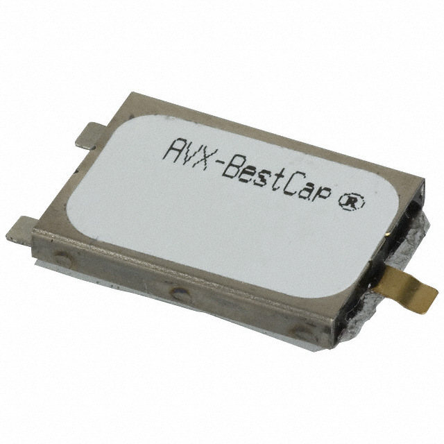
ICGOO电子元器件商城为您提供BZ05FB682ZSB由AVX设计生产,在icgoo商城现货销售,并且可以通过原厂、代理商等渠道进行代购。 BZ05FB682ZSB价格参考¥109.19-¥156.91。AVXBZ05FB682ZSB封装/规格:双电层电容器 (EDLC),超级电容器, 6.8mF (EDLC) Supercapacitor 15V BZ05, 3 Lead 500 mOhm 1000 Hrs @ 70°C。您可以下载BZ05FB682ZSB参考资料、Datasheet数据手册功能说明书,资料中有BZ05FB682ZSB 详细功能的应用电路图电压和使用方法及教程。
AVX Corporation 的 BZ05FB682ZSB 是一款双电层电容器(EDLC),属于超级电容器类别。该器件主要应用于需要高脉冲功率、快速充放电和长循环寿命的场景。

典型应用场景包括:

1. 能量存储与备份电源:用于在主电源中断时提供短期能量支持,如智能电表、工业控制系统和通信设备中的数据保存与应急操作。

2. 物联网(IoT)设备:为低功耗无线传感器节点、可穿戴设备等提供瞬时高功率支持,满足数据传输时的脉冲功率需求。

3. 汽车电子系统:如启停系统、车载导航、紧急呼叫系统(eCall)等,用于应对电压波动或短暂断电情况,确保系统稳定运行。

4. 工业自动化设备:作为备用电源支持编码器、PLC控制器或无线传感器,保障关键数据在断电时的写入与保存。

5. 便携式医疗设备:提供可靠、快速响应的电源支持,确保设备在突发断电时仍能完成关键操作。

该电容器具有高可靠性、低内阻(ESR)和长寿命特点,适用于对体积敏感且需高效能量管理的设计。
| 参数 | 数值 |
| 产品目录 | |
| 描述 | CAP SUPER 0.0068F 15V BZ05 SMD超级电容/超级电容器 15volt 6.80MF 80-20% |
| ESR | 600 mOhms |
| ESR(等效串联电阻) | 500 毫欧 |
| 产品分类 | |
| 品牌 | AVX |
| 产品手册 | |
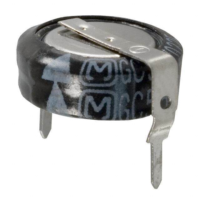
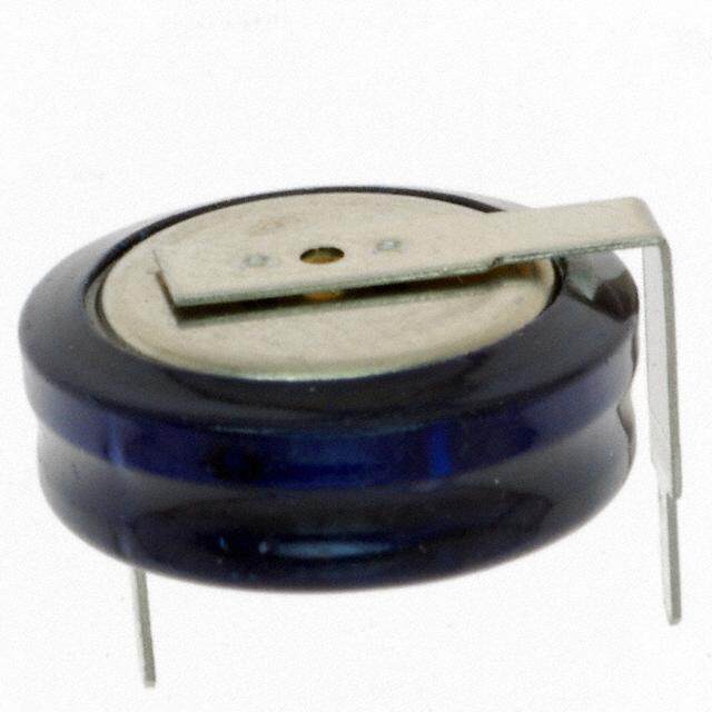
| 产品图片 |
|
| rohs | 符合RoHS无铅 / 符合限制有害物质指令(RoHS)规范要求 |
| 产品系列 | 超级电容/超级电容器,AVX BZ05FB682ZSBBestCap® BZ |
| 数据手册 | |
| 产品型号 | BZ05FB682ZSB |
| 不同温度时的使用寿命 | 70°C 时为 1000 小时 |
| 产品 | Supercapacitors |
| 产品种类 | 超级电容/超级电容器 |
| 其它名称 | 478-6277 |
| 包装 | 散装 |
| 商标 | AVX |
| 商标名 | BestCap |
| 外壳宽度 | 15 mm |
| 外壳长度 | 20 mm |
| 外壳高度 | 2.3 mm to 6.5 mm |
| 大小/尺寸 | 0.787" 长 x 0.591" 宽(20.00mm x 15.00mm) |
| 安装类型 | 表面贴装 |
| 容差 | - 20 %, + 80 % |
| 封装 | Bulk |
| 封装/外壳 | BZ05,3 引线 |
| 工作温度 | -20°C ~ 70°C |
| 工作温度范围 | - 20 C to + 70 C |
| 工厂包装数量 | 400 |
| 引线间距 | - |
| 标准包装 | 400 |
| 漏泄电流 | 10 uA |
| 电压-额定 | 15V |
| 电压额定值 | 15 V |
| 电容 | 6.8 mF |
| 端接类型 | SMD/SMT |
| 系列 | B |
| 高度-安装(最大值) | 0.228"(5.80mm) |


- 商务部:美国ITC正式对集成电路等产品启动337调查
- 曝三星4nm工艺存在良率问题 高通将骁龙8 Gen1或转产台积电
- 太阳诱电将投资9.5亿元在常州建新厂生产MLCC 预计2023年完工
- 英特尔发布欧洲新工厂建设计划 深化IDM 2.0 战略
- 台积电先进制程称霸业界 有大客户加持明年业绩稳了
- 达到5530亿美元!SIA预计今年全球半导体销售额将创下新高
- 英特尔拟将自动驾驶子公司Mobileye上市 估值或超500亿美元
- 三星加码芯片和SET,合并消费电子和移动部门,撤换高东真等 CEO
- 三星电子宣布重大人事变动 还合并消费电子和移动部门
- 海关总署:前11个月进口集成电路产品价值2.52万亿元 增长14.8%


PDF Datasheet 数据手册内容提取
AVX BestCap® Ultra-low ESR High Power Pulse Supercapacitors m o c . x v a w. w w Version 12.6
BestCap® Ultra-low ESR High Power Pulse Supercapacitors Table of Contents An Introduction to BestCap® 2 . . . . . . . . . . . . . . . . . . . . . . . . . . . . . . . . . . . . . . . . . . . . . . . . . . . . . . . . . . . . . . . . . . . . . . . . . . . . . . . . . . . . . . . . . . . . . . . . . . . . . . BestCap® General Information 3 . . . . . . . . . . . . . . . . . . . . . . . . . . . . . . . . . . . . . . . . . . . . . . . . . . . . . . . . . . . . . . . . . . . . . . . . . . . . . . . . . . . . . . . . . . . . . . . . . . . SECTION 1: Electrical Ratings (A-B Series) 4 . . . . . . . . . . . . . . . . . . . . . . . . . . . . . . . . . . . . . . . . . . . . . . . . . . . . . . . . . . . . . . . . . . . . . . . . . . . . Electrical Ratings (BZ01/02/05/09) 5 . . . . . . . . . . . . . . . . . . . . . . . . . . . . . . . . . . . . . . . . . . . . . . . . . . . . . . . . . . . . . . . . . . . . . . SECTION 2: Mechanical Specifications (A-Lead) 7 . . . . . . . . . . . . . . . . . . . . . . . . . . . . . . . . . . . . . . . . . . . . . . . . . . . . . . . . . . . . . . . . . . . Mechanical Specifications (W-Lead) 8 . . . . . . . . . . . . . . . . . . . . . . . . . . . . . . . . . . . . . . . . . . . . . . . . . . . . . . . . . . . . . . . . . . Mechanical Specifications (H-Lead) 9 . . . . . . . . . . . . . . . . . . . . . . . . . . . . . . . . . . . . . . . . . . . . . . . . . . . . . . . . . . . . . . . . . . . Mechanical Specifications (L-Lead) 10 . . . . . . . . . . . . . . . . . . . . . . . . . . . . . . . . . . . . . . . . . . . . . . . . . . . . . . . . . . . . . . . . . . Mechanical Specifications (N-Lead) 11 . . . . . . . . . . . . . . . . . . . . . . . . . . . . . . . . . . . . . . . . . . . . . . . . . . . . . . . . . . . . . . . . . Mechanical Specifications (S-Lead) 12 . . . . . . . . . . . . . . . . . . . . . . . . . . . . . . . . . . . . . . . . . . . . . . . . . . . . . . . . . . . . . . . . . . Packaging Specifications (BZ01/02/05/09) 13 . . . . . . . . . . . . . . . . . . . . . . . . . . . . . . . . . . . . . . . . . . . . . . . . . . . . . . . Packaging Quantities 13 . . . . . . . . . . . . . . . . . . . . . . . . . . . . . . . . . . . . . . . . . . . . . . . . . . . . . . . . . . . . . . . . . . . . . . . . . . . . . . . . . . . . . . . . . Cleaning/Handling/Storage Conditions/Part Marking/Termination Finish 14 . . . . Product Safety Materials Handling/Materials and Weight 15 . . . . . . . . . . . . . . . . . . . . . . . . . . . . . . Typical Weight Data 15 . . . . . . . . . . . . . . . . . . . . . . . . . . . . . . . . . . . . . . . . . . . . . . . . . . . . . . . . . . . . . . . . . . . . . . . . . . . . . . . . . . . . . . . . . . . . SECTION 3: Electrical Characteristics – Schematic, Typical Characteristics 16 . . . . . . . . . . . . . . . . . . . . Mounting Procedure on a PCB for BestCap® 17 . . . . . . . . . . . . . . . . . . . . . . . . . . . . . . . . . . . . . . . . . . . . . . . . . . . Qualification Test Summary 18 . . . . . . . . . . . . . . . . . . . . . . . . . . . . . . . . . . . . . . . . . . . . . . . . . . . . . . . . . . . . . . . . . . . . . . . . . . . . . . . SECTION 4: Application Notes 19 . . . . . . . . . . . . . . . . . . . . . . . . . . . . . . . . . . . . . . . . . . . . . . . . . . . . . . . . . . . . . . . . . . . . . . . . . . . . . . . . . . . . . . . . . . . . . . . BestCap® Construction/Voltage Drop 19 . . . . . . . . . . . . . . . . . . . . . . . . . . . . . . . . . . . . . . . . . . . . . . . . . . . . . . . . . . . . . . . Enhancing the Power Capability of Primary Batteries 21 . . . . . . . . . . . . . . . . . . . . . . . . . . . . . . . . . . . . BestCap® for GSM/GPRS PCMCIA Modems 22 . . . . . . . . . . . . . . . . . . . . . . . . . . . . . . . . . . . . . . . . . . . . . . . . . . . . SECTION 5: Extended Temperature Range 23 . . . . . . . . . . . . . . . . . . . . . . . . . . . . . . . . . . . . . . . . . . . . . . . . . . . . . . . . . . . . . . . . . . . . . . . . . . . NOTICE: Specifications are subject to change without notice. Contact your nearest AVX Sales Office for the latest specifications. All statements, information and data given herein are believed to be accurate and reliable, but are presented without guarantee, warranty, or responsibility of any kind, expressed or implied. Statements or suggestions concerning possible use of our products are made without representation or warranty that any such use is free of patent infringement and are not recommendations to infringe any patent. The user should not assume that all safety measures are indicated or that other measures may not be required. Specifications are typical and may not apply to all applications.
BestCap® Ultra-low ESR High Power Pulse Supercapacitors INTRODUCING BESTCAP®: A NEW GENERATION OF PULSE SUPERCAPACITORS Supercapacitors (also referred to as Electrochemical There are, however, two limitations associated with Capacitors or Double Layer Capacitors) have rapidly become conventional supercapacitors, namely: high ESR in the tens recognized, not only as an excellent compromise between of Ohms range, and high capacitance loss when required to “electronic” or “dielectric” capacitors such as ceramic, supply very short duration current pulses. BestCap® tantalum, film and aluminum electrolytic, and batteries (Figure successfully addresses both of these limitations. 1), but also as a valuable technology for providing a unique The capacitance loss in the millisecond region is caused by combination of characteristics, particularly very high energy, the charge transfer (i.e. establishment of capacitance) being power and capacitance densities. carried out primarily by relatively slow moving ions in double layer capacitors. Figure 1. Specific Energy of Capacitor Types 10000 SPECIFIC ENERGY 1000 S p ® ec ific E n e 100 rg y (m F TA N TA L U M E LECTROCLAYTPAICCITOR 10 V/cc) ELPEOACLLYTURMMOEILRNYUTIMC 1 0.1 1 10 100 1000 10000 Capacitance (mF) In the above-mentioned “electronic” capacitors, the charge by several varieties of supercapacitors under short pulse transfer is performed by fast electrons, thereby creating width conditions. It can also be seen from Figure 2 how well virtually instant rated capacitance value. In the BestCap®, a BestCap®retains its capacitance with reducing pulse widths. unique proton polymer membrane is used – charge transfer For comparison purposes, the characteristic of an equivalent by protons is close to the transfer rate for electrons and capacitance value aluminum electrolytic capacitor is shown orders of magnitude greater than organic molecules. Figure in Figure 2. The electrolytic capacitor is many times the vol- 2 below illustrates the severe capacitance loss experienced ume of the BestCap®. Figure 2. Actual Capacitance vs. Pulse Width 100% al) n EDLC-Electrochemical mi 80% o double layer capacitor N ® of 60% % Aluminum Electrolytic Capacitor p. ( 40% manufacturer A EDLC Ca manufacturer B EDLC al 20% manufacturer C EDLC u ct A 0% 1000 100 10 1 Pulse Width (msec) 2
BestCap® Ultra-low ESR High Power Pulse Supercapacitors BESTCAP® – A SERIES – MAXIMUM CAPACITANCE, LOW ESR B SERIES – LOW PROFILE, LOW ESR The BestCap®is a low profile device available in four case sizes. Capacitance range is from 6.8mF to 1000mF and includes 7 voltage ratings from 3.6V to 16V. BESTCAP® – AVAILABLE LEAD CONFIGURATIONS STANDARD: N-Style: Two Terminal Planar Mount S-Style: Three Terminal Planar Mount L-Style: Four Terminal Planar Mount (Available in BZ01, BZ05, BZ09 case only) (Available in BZ01, BZ05, BZ09 case only) (Available in BZ01 and BZ02 case only) A Style: Through-Hole Mount H-Style: Extended Stand-Off Through Hole Mount W-Style: Wire Lead Mount (Available in BZ01, BZ02 case only) (Available in BZ01, BZ02 case only) (Available in BZ01, BZ05 case only) BODY DIMENSIONS Case Size L ±0.5 (0.020) W ±0.2 (0.008) H nom mm (inches) mm (inches) mm (inches) BZ01 28 (1.102) 17 (0.669) 2.3 (0.091) – 6.5 (0.256) BZ02 48 (1.890) 30 (1.181) 2.9 (0.114) – 6.8 (0.268) LEAD-FREE COMPATIBLE BZ05 20 (0.787) 15 (0.590) 2.3 (0.091) – 6.5 (0.256) COMPONENT BZ09 17 (0.669) 15 (0.590) 2.3 (0.091) ELECTRICAL SPECIFICATIONS Full dimensional specifications shown in section (2) Capacitance range: 6.8mF – 1000mF Capacitance tolerance: +80% / –20% Voltage ratings (max): 3.6V 4.5V 5.5V 9V 12V 15V 16V 20V Test voltages: 3.5V 4.2V 5.0V 8.4V 10.0V 11.0V 13.0V 16.0V Surge test voltage: 4.5V 5.6V 6.9V 11.3V 15.0V 18.8V 20.0V 25.0V Temperature range: –20°C to 70°C, consult factory for -40ºC and +75ºC options HOW TO ORDER (See Detailed Electrical Specifications for valid combinations) BZ 0 1 5 A 503 Z A B XX BestCap® Standard Case Size Rated Series Capacitance Capacitance Lead Packaging Not Used For 0 = Standard 1 = 28mmx17mm Voltage A = Maximum Code Tolerance Format B = Bulk Standard 1 = High Cap 2 = 48mmx30mm 3 = 3.6V Capacitance (Farad Code) Z = (+80/-20)% A, H, L, N, Product 5 = 20mmx15mm 4 = 4.5V B = Low Profile 8 = (+50/-20)% S or W (Consult 9 = 17mmx15mm 5 = 5.5V P = (+100/-0)% Factory For 9 = 9.0V N = (+30/-30)% Special C = 12.0V Requirements) F = 15.0V G = 16.0V 3 K = 20.0V
BestCap® Ultra-low ESR High Power Pulse Supercapacitors SECTION 1: ELECTRICAL RATINGS CAPACITANCE / VOLTAGE / CASE SIZE MATRIX A-SERIES – MAXIMUM CAPACITANCE Capacitance Rated Voltage DC at 25°C mF Code 3.6V 5.5V 9.0V 12.0V 16.0V Case Lead Case Lead Case Lead Case Lead Case Lead Size Styles Size Styles Size Styles Size Styles Size Styles 10 103 BZ05 N, S 22 223 BZ01 A, H, S 33 333 BZ05 N, S, W BZ01 A, H, S 47 473 BZ11 S 50 503 BZ01 A, H, S, L 68 683 BZ05 S 70 703 BZ01 A, H, S, L 90 903 BZ02 A, H, L 100 104 BZ01 A, H, S, L 120 124 BZ02 A, H, L BZ12 A, L 140 144 BZ01 A, H, S, L 150 154 BZ15 S 200 204 BZ02 A, H, L 280 284 BZ02 A, H, L 400 404 BZ02 A, H, L 470 474 BZ12 A 560 564 BZ02 A, H, L 1000 105 BZ12 A, H, L B-SERIES – LOW PROFILE Capacitance Rated Voltage DC at 25°C mF Code 3.6V 4.5V 5.5V 9.0V 12.0V 15.0V 20.0V Case Lead Case Lead Case Lead Case Lead Case Lead Case Lead Case Lead Size Styles Size Styles Size Styles Size Styles Size Styles Size Styles Size Styles 4.7 472 BZ05 N, S, W 6.8 682 BZ05 N, S, W BZ01 N, S, W 15 153 BZ09 N, S, W BZ05 N, S, W BZ01 A, H, S 22 223 BZ05 N, S, W BZ01 A, H, S 30 303 BZ01 S, N 33 333 BZ01 S, N, W BZ05 S, N, W 47 473 BZ15 N, S, W BZ11 S 50 503 BZ01 S, N, W 60 603 BZ01 A, H, S, L 100 104 BZ11 S, N, W 4
BestCap® Ultra-low ESR High Power Pulse Supercapacitors SECTION 1: ELECTRICAL RATINGS ELECTRICAL RATINGS - SEE SECTION 2 FOR DIMENSIONAL REFERENCES BZ 01 CASE SIZE Rated Leakage Height S-Lead Part Capacitance ESR Height A-Lead Height H-Lead Height S-Lead Voltage Current (AJ)* Number (mF) (mOhms at 1 kHz) (mm) (mm) (Volts) (µA max) (mm) (mm) Nominal +80%, –20% Typical Maximum Maximum H max H max H max H max 3.6V BZ013B503Z_B 50 100 120 5 NA NA 3.2 2.1 BZ013A703Z_B 70 140 168 5 3.5 6.4 4.0 2.9 3.6V BZ113B104Z_B 100 100 120 10 NA NA 3.2 2.1 BZ013A144Z_B 140 70 84 5 5.3 8.2 5.8 NA 4.5V BZ014B333Z_B 4.5V 33 150 180 5 NA NA 3.5 2.4 5.5V BZ015B303Z_B 30 160 192 5 NA NA 3.8 2.7 BZ015A503Z_B 50 160 192 5 4.1 7.0 4.6 3.5 5.5V BZ015B603Z_B 60 80 96 10 5.4 8.3 5.9 NA BZ015A104Z_B 100 80 96 10 6.7 9.6 7.2 NA 9.0V BZ019B223Z_B 22 250 300 5 4.7 7.6 5.2 4.1 9.0V BZ019A333Z_B 33 250 300 5 5.5 8.4 6.0 4.9 12.0V BZ01CB153Z_B 15 350 420 5 5.9 8.8 6.4 5.3 12.0V BZ01CA223Z_B 22 350 420 5 7.1 10.0 7.6 6.5 16.0V BZ01GB682ZSB 16.0V 6.8 400 480 10 6.8 20.0V BZ01KB682ZSB 20.0V 6.8 400 480 10 6.8 * Select S-Lead BZ01 BestCap® are available with insulation on the bottom of the part and zero clearance from the PCB. See section 2.6 for dimensions. To order, please add special requirement AJ to the end of the part number. Example: BZ013B503ZSBAJ BZ 02 CASE SIZE Rated Leakage Part Capacitance ESR Height A-Lead Height H-Lead Height L-Lead Voltage Current Number (mF) (mOhms at 1 kHz) (mm) (mm) (mm) (Volts) (µA max) Nominal +80%, –20% Typical Maximum Maximum H max H max H max 3.6V BZ023A284Z_B 280 45 54 20 3.5 6.4 3.7 3.6V BZ023A564Z_B 560 25 30 40 5.3 8.2 5.5 5.5V BZ025A204Z_B 200 60 72 20 4.1 7.0 4.3 BZ025A404Z_B 5.5V 400 35 42 40 6.7 9.6 6.9 BZ125A105Z_B 1000 35 42 120 6.7 9.6 6.9 9.0 V BZ029A124Z_B 9.0V 120 70 84 20 5.8 8.7 6.0 12.0V BZ02CA903Z_B 12.0V 90 90 108 20 7.4 10.3 7.6 16.0V BZ12GA124Z_B 16.0V 120 160 192 60 9.1 9.1 All capacitance, ESR, and leakage current values listed in these tables are at room temperature only. 5
BestCap® Ultra-low ESR High Power Pulse Supercapacitors BZ 05 CASE SIZE Rated Leakage Part Capacitance ESR Height N-Lead Height S-Lead Voltage Current Number (mF) (mOhms at 1 kHz) (mm) (mm) (Volts) (µA max) Nominal +80%, –20% Typical Maximum Maximum H max H max 4.5V BZ054B223Z_B 22 170 204 5 2.3 2.3 4.5V BZ154B473Z_B 47 170 204 10 2.3 2.3 5.5V BZ055B153Z_B 15 250 300 5 2.7 2.7 BZ055A333Z_B 5.5V 33 250 300 5 3.5 3.5 BZ055B333Z_B 33 125 150 10 NA 4.8 BZ155A104Z_B 100 125 150 20 NA 6.1 12.0V BZ05CA103Z_B 12.0V 10 500 600 55 6.5 6.5 15.0V BZ05FB682Z_B 15.0V 6.8 500 600 10 5.8 5.8 20.0V BZ05KB472ZSB 20.0V 4.7 700 840 10 6.7 BZ 09 CASE SIZE Rated Leakage Part Capacitance ESR Height N-Lead Height S-Lead Voltage Current Number (mF) (mOhms at 1 kHz) (mm) (mm) (Volts) (µA max) Nominal +80%, –20% Typical Maximum Maximum H max H max 4.5V BZ094B153Z_BAI 4.5V 15 250 300 5 2.4* 2.3* * The 4.5V BZ09 BestCap® are available only in a special low profile version. All capacitance, ESR, and leakage current values listed in these tables are at room temperature only. 6
BestCap® Ultra-low ESR High Power Pulse Supercapacitors SECTION 2: MECHANICAL SPECIFICATIONS 2.1 Case Dimensions & Recommended PCB Layout 2.1.1: A-Style Configuration (Pin Through Hole) L BL W LO H LL S LW TABLE 2.1.1: A-STYLE DIMENSIONS Case Dimensions: mm (inches) Case Size BL W H L S LO LW LL +1.0 (0.040)/-0 +1.0 (0.040)/-0 (Maximum) ±1.0 (0.040) ±0.1 (0.004) ±0.2 (0.008) ±0.2 (0.008) ±0.2 (0.008) BZ01 28 (1.102) 17 (0.669) See Section 1 32 0.45 (0.018) 1.5 (0.059) 1.27 (0.050) 2.5 (0.098) BZ02 48 (1.890) 30 (1.181) See Section 1 52 0.45 (0.018) 1.5 (0.059) 1.27 (0.050) 2.5 (0.098) 2.1.2: A-Lead Configuration (Through Hole) C D A B TABLE 2.1.2: A-LEAD LAYOUT DIMENSIONS Recommended PCB Dimensions: mm (inches) Case Size A B C D ±0.05 (0.002) ±0.05 (0.002) ±0.05 (0.002) ±0.1 (0.004) BZ01 17.25 (0.679) 8.90 (0.350) 28 (1.102) Ø1.4 (0.055) BZ02 30.25 (1.191) 8.90 (0.350) 48 (1.890) Ø1.4 (0.055) 7
BestCap® Ultra-low ESR High Power Pulse Supercapacitors SECTION 2: MECHANICAL SPECIFICATIONS (cont’d) 2.2.1: W-Style Case Dimensions L BL RED B W BLACK H TABLE 2.2.1: W-STYLE CASE DIMENSIONS Case Dimensions: mm (inches) L W H BL B Case Size ±0.5 (0.020) +1.0 (0.040)/-0 (Maximum) +1.0 (0.040)/-0 ±0.5 (0.020) BZ05 50.5 (1.988) 15 (0.591) See Section 1 25.4 (1.0) 10 (0.394) 8
BestCap® Ultra-low ESR High Power Pulse Supercapacitors SECTION 2: MECHANICAL SPECIFICATIONS (cont’d) 2.3.1: H-Style Case Dimensions (Through Hole Extended Height) L BL W H LO LL S LW TABLE 2.3.1: H-STYLE CASE DIMENSIONS Case Dimensions: mm (inches) S BL W H L LO LW LL Case Size +0.5 (0.020)/ +1.0 (0.040)/-0 +1.0 (0.040)/-0 (Maximum) ±1.0 (0.040) ±0.2 (0.008) ±0.2 (0.008) ±0.2 (0.008) -0.4 (0.016) BZ01 28 (1.102) 17 (0.669) See Section 1 32 (1.260) 3.0 (0.118) 1.5 (0.059) 1.27 (0.050) 2.5 (0.098) BZ02 48 (1.890) 30 (1.181) See Section 1 52 (2.047) 3.0 (0.118) 1.5 (0.059) 1.27 (0.050) 2.5 (0.098) BZ05 20 (0.787) 15.6 (0.614) See Section 1 24.3 (0.957) 3.0 (0.118) 1.5 (0.059) 1.27 (0.050) 2.5 (0.098) 2.3.2: H-Lead Configuration (Through Hole Extended Height) C D A B TABLE 2.3.2: H-LEAD LAYOUT DIMENSIONS PCB Dimensions: mm (inches) Case Size A B C D ±0.05 (0.002) ±0.05 (0.002) ±0.05 (0.002) ±0.1 (0.004) BZ01 17.25 (0.679) 8.90 (0.350) 28 (1.102) Ø1.4 (0.055) BZ02 30.25 (1.191) 8.90 (0.350) 48 (1.890) Ø1.4 (0.055) BZ05 15.25 (0.600) 8.90 (0.350) 19 (0.748) Ø1.4 (0.055) 9
BestCap® Ultra-low ESR High Power Pulse Supercapacitors SECTION 2: MECHANICAL SPECIFICATIONS (cont’d) 2.4.1: L-Lead Configuration (Planar Mount) L BL W LO LL LW H S TABLE 2.4.1: L-STYLE CASE DIMENSIONS Case Dimensions: mm (inches) Case Size BL W H L S LO LW LL +1.0 (0.040)/-0 +1.0 (0.040)/-0 (Maximum) ±1.0 (0.040) ±0.2 (0.008) ±0.2 (0.008) ±0.2 (0.008) ±0.5 (0.020) BZ01 28 (1.102) 17 (0.6691) See Section 1 33 0.55 (0.022) 1.5 (0.059) 1.27 (0.050) 2.4 (0.098) BZ02 48 (1.890) 30 (1.181) See Section 1 52 0.55 (0.022) 1.5 (0.059) 1.27 (0.050) 2.4 (0.098) 2.4.2: L-Lead Configuration (Planar Mount) C A B PW PL TABLE 2.4.2: L-STYLE LEAD LAYOUT PCB Dimensions: mm (inches) Case Size A B C PL PW ±0.1 (0.004) ±0.1 (0.004) ±0.1 (0.004) ±0.2 (0.008) ±0.2 (0.008) BZ01 19.2 (0.776) 10.8 (0.425) 28 (1.102) 3.0 (0.118) 3.7 (0.146) BZ02 32.2 (1.268) 10.8 (0.425) 48 (1.890) 3.2 (0.126) 3.7 (0.146) 10
BestCap® Ultra-low ESR High Power Pulse Supercapacitors SECTION 2: MECHANICAL SPECIFICATIONS (cont’d) 2.5.1: N-Lead Configuration L BL LL LW W CL B EW EL H TABLE 2.5.1: N-STYLE CASE DIMENSIONS Case Dimensions: mm (inches) Case Size L W H B LL LW EL EW ±0.5 (0.020) +1.0 (0.040)/-0 (Maximum) ±0.5 (0.020) ±0.2 (0.008) ±0.2 (0.008) ±0.5 (0.020) ±0.5 (0.020) BZ01 30.5 (1.201) 17 (0.669) See Section 1 11.2 (0.441) 2.5 (0.098) 1.4 (0.055) 2.5 (0.098) 1.4 (0.055) BZ05 23.5 (0.925) 15 (0.591) See Section 1 7.5 (0.295) 2.5 (0.098) 2.5 (0.098) 3.5 (0.138) 2.5 (0.098) BZ09 20.5 (0.807) 15 ( 0.591) See Section 1 7.5 (0.295) 2.5 (0.098) 2.5 (0.098) 3.5 (0.138) 2.5 (0.098) 2.5.2: N-Lead Configuration (Planar Mount) A PW LPL B RPL TABLE 2.5.2: N-STYLE LEAD LAYOUT PCB Dimensions: mm (inches) Case Size A B PW LPL RPL ±0.5 (0.020) ±0.1 (0.004) ±0.1 (0.004) ±0.1 (0.004) ±0.1 (0.004) BZ01 0.5 (0.020) 9.5 (0.374) 3.2 (0.126) 3.5 (0.138) 3.5 (0.138) BZ05 1.0 (0.039) 5.9 (0.232) 4.1 (0.161) 2.5 (0.098) 3.5 (0.138) BZ09 1.0 (0.039) 5.9 (0.232) 4.1 (0.161) 2.5 (0.098) 3.5 (0.138) 11
BestCap® Ultra-low ESR High Power Pulse Supercapacitors SECTION 2: MECHANICAL SPECIFICATIONS (cont’d) 2.6.1: S-Lead Configuration (Planar Mount) L BL W EW EL LW LL S H TABLE 2.6.1: S-STYLE CASE DIMENSIONS Case Dimensions: mm (inches) Case Size BL W H L EL EW LL LW +1.0 (0.040)/-0 +1.0 (0.040)/-0 (Maximum) ±1.0 (0.040) ±0.5 (0.020) ±0.2 (0.008) ±0.5 (0.020) ±0.2 (0.008) BZ01 28 (1.102) 17 (0.669) See Section 1 38.7 (1.524) 5.0 (0.197) 4.5 (0.177) 5.7 (0.224) 2.0 (0.079) BZ05 20 (0.787) 15 (0.591) See Section 1 26 (1.024) 3.5 (0.138) 2.5 (0.098) 2.5 (0.098) 2.5 (0.098) BZ09 17 (0.669) 15 (0.591) See Section 1 23 (0.906) 3.5 (0.138) 2.5 (0.098) 2.5 (0.098) 2.5 (0.098) 2.6.2: S-Lead Layout (Planar Mount) Planar Mount “S” B Available in BZ01, BZ05 & BZ09 Case Size Only A EPW LPW EPL LPL TABLE 2.6.2: S-STYLE PAD LAYOUT DIMENSIONS PCB Dimensions: mm (inches) Case Size A B EPL EPW LPL LPW ±0.1 (0.004) ±0.1 (0.004) ±0.1 (0.004) ±0.1 (0.004) ±0.1 (0.004) ±0.1 (0.004) BZ01 13.0 (0.512) 35.1 (1.382) 4.5 (0.177) 6.0 (0.236) 5.8 (0.228) 3.5 (0.138) BZ05 10.0 (0.394) 25.0 (0.984) 3.0 (0.118) 4.5 (0.177) 2.9 (0.114) 4.5 (0.177) BZ09 10.0 (0.394) 22.0 (0.886) 3.0 (0.118) 4.5 (0.177) 2.9 (0.114) 4.5 (0.177) 12
BestCap® Ultra-low ESR High Power Pulse Supercapacitors SECTION 2: MECHANICAL SPECIFICATIONS (cont’d) 2.7: Packaging Specifications 167.6 (6.60) BZ01 Case: (520.0.80) (103.5.22) 31.8 (1.25) 167.6 (6.60) BZ02 Case: 167.6 (6.60) (721.8.00) (103.5.22) 38.1 (1.50) 167.6 (6.60) BZ05, BZ09 Case: 167.6 (6.60) (318.5.10) (103.5.22) 28.6 (1.12) 167.6 (6.60) This specification applies when our electrochemical supercapacitors are packed using a 165mm by 165mm container. The parts are held in place by a 166mm by 166mm lid. PACKAGING QUANTITIES: Size No. of Rows No. of Columns Pieces/Tray BZ01 5 3 15 BZ02 4 2 8 BZ05 5 4 20 BZ09 5 4 20 13
BestCap® Ultra-low ESR High Power Pulse Supercapacitors SECTION 2: MECHANICAL SPECIFICATIONS 2.8 CLEANING The BestCap® supercapacitor is cleaned prior to shipment. Should cleaning be required prior to insertion into the applica- tion, it is recommended to use a small amount of propanol taking care not to remove the label. The cell should not be immersed due to possible deterioration of the epoxy encap- sulation. Care must also be taken not to bend the leads. 2.9 HANDLING Care should be taken not to allow grease or oil into the part as it may lead to soldering problems. Handling should be minimized to reduce possible bending of the electrodes leads. 2.10 STORAGE CONDITIONS AVX BestCap® supercapacitor is unaffected by the following storage conditions: Temperature: 15°C ~ 35°C Humidity: 45% RH ~ 75% RH This temperature and humidity range is specified for consid- eration of terminal solderability. BestCap® are able to with- stand shelf life at 70ºC for 1000 hours. 2.11 PART MARKING Voltage Capacitance Date and Lot Code Country of Origin 2.12 TERMINATION FINISH Gold over nickel, tin over nickel. 14
BestCap® Ultra-low ESR High Power Pulse Supercapacitors 2.13 PRODUCT SAFETY MATERIALS HANDLING Precautions internal components, it is recommended to wash the skin (cid:129) Do not disassemble the capacitor. with excess of running water. (cid:129) Do not incinerate the capacitor and do not use incineration (cid:129) If any internal material contacts the eyes, rinse thoroughly for disposal. with running water. (cid:129) The capacitor contains polymeric electrolyte and carbon (cid:129) Be aware not to apply over-voltage. Combination of electrodes. However, since the polymer is composed of charging at voltage greater than the nominal, plus high acid based chemical ingredients, if punctured or temperature, plus prolonged time may result in capacitor dismantled and the skin is contacted with the capacitor bulging or rupturing. 2.14 BESTCAP® MATERIALS AND WEIGHT RoHS BZ01 BZ02 BZ05 BZ09 Materials Constituent Compliant? Weight % Weight % Weight % Weight % Case Stainless Steel YES 56.7% 44.5% 64.8% 64.8% Leads (A, H, and L lead only) Stainless Steel YES 4.2% 0.7% Electrode Stainless Steel YES 13.6% 8.0% 13.6% 13.6% Electrode Insulation Laminating Adhesive YES 2.3% 1.0% 2.4% 2.4% Core Metallized Current Collector YES 5.2% 8.0% 1.6% 1.6% Current Collector YES 2.5% 14.3% 1.0% 1.0% Active Electrode YES 1.0% 5.7% 0.4% 0.4% Core Sealant YES 0.9% 5.2% 0.3% 0.3% Encapsulant Epoxy YES 10.3% 11.4% 11.8% 11.8% Bottom Insulation Laminating Adhesive YES 2.3% 1.0% 2.4% 2.4% Label Label YES 1.0% 0.2% 1.8% 1.8% TOTAL 100% 100% 100% 100% BestCap®is RoHS compliant May be assembled with Pb-Free solder. BESTCAP® – TYPICAL WEIGHT DATA Rated Voltage (V) Capacitance (mF) Part Number Weight (g) 3.6V 50 BZ013B503Z_B 2.9 70 BZ013A703Z_B 4.2 100 BZ113B104Z_B 2.9 140 BZ013A144Z_B 5.3 280 BZ023A284Z_B 12.2 560 BZ023A564Z_B 15.9 4.5V 15 BZ094B153Z_B 1.5 22 BZ054B223Z_BBQ 1.8 33 BZ014B333Z_B 3.2 47 BZ154B473Z_BBQ 1.8 5.5V 15 BZ055B153Z_B 1.9 30 BZ015B303Z_B 3.4 33 BZ055A333Z_B 2.3 33 BZ055B333Z_B 2.1 50 BZ015A503Z_B 4.6 60 BZ015B603Z_B 5.5 68 BZ055A683Z_B 3.4 100 BZ015A104Z_B 6.1 200 BZ025A204Z_B 13.3 400 BZ025A404Z_B 18.4 1000 BZ125A105Z_B 18.4 9.0V 22 BZ019B223Z_B 4.4 33 BZ019A333Z_B 5.0 120 BZ029A124Z_B 15.6 12.0V 10 BZ05CA103Z_B 3.5 15 BZ01CB153Z_B 5.0 22 BZ01CA223Z_B 6.2 90 BZ02CA903Z_B 19.3 15.0V 6.8 BZ05FB682Z_B 2.8 16.0V 124 BZ12GA124Z_B 25 15
BestCap® Ultra-low ESR High Power Pulse Supercapacitors SECTION 3: ELECTRICAL CHARACTERISTICS – SCHEMATIC 3.1 Terminal Connections: 3.1.2: A-, H- & L-Lead 3.1.3: C- & N-Lead 3.1.1: S-Lead Common terminals connected to case Common terminals connected to case Devices are non polar but it is usual to maintain case at ground potential SECTION 3.2: TYPICAL CHARACTERISTICS Capacitance vs. Temperature ESR vs. Temperature 0.07 0.700 0.06 0.600 s) ad 0.05 0.500 e (Far 0.04 hms)0.400 c O acitan 00..0032 ESR (00..320000 p a C 0.01 0.100 0 0.000 -25-20-15-10-5 0 5 10 15 20 25 30 35 40 45 50 55 60 65 -25-20-15-10-5 0 5 10 15 20 25 30 35 40 45 50 55 60 65 BZ015A503ZLB35 Temperature (°C) BZ015A503ZLB35 Temperature (°C) ESR vs. Frequency ESR Comparison 10 BZ015A503 1.00E+01 BZ014A104 BZ015A503 BZ025A204 BZ014A104 BZ025A204 ms) 1 s)1.00E+00 h m O h SR ( R (O E0.1 ES1.00E-01 0.01 1.00E-02 10 100 1,000 10,000 100,000 1,000,00010,000,000100,000,000 10 100 1,000 10,000 100,000 1,000,00010,000,000100,000,000 Frequency (Hz) Frequency (Hz) Impedance vs. Frequency Impedance Comparison 10 10 BZ015A503 BZ015A503 BZ014A104 BZ014A104 BZ025A204 BZ025A204 ms) 1 ms) 1 Oh Oh mpedance ( 0.1 mpedance ( 0.1 I I 0.01 0.01 10 100 1,000 10,000 100,000 1,000,00010,000,000100,000,000 10 100 1,000 10,000 100,000 1,000,00010,000,000100,000,000 Frequency (Hz) Frequency (Hz) 16
BestCap® Ultra-low ESR High Power Pulse Supercapacitors SECTION 3.3: MOUNTING PROCEDURE ON A PCB FOR BESTCAP® BestCap® products can be mounted on PCBs by either selectively heating only the capacitor terminals by using a pulsed reflow soldering station or by using hand soldering. IR Reflow or wave soldering may not be used. The main body of the device should be less than 60ºC at all times. PULSED REFLOW SOLDERING HAND SOLDERING STATION Application data for the ‘Unitek’ pulsed-reflow soldering Equipment: Temperature controlled, 50W general station. purpose iron Solder type: 63Sn/37Pb, rosin core wire Equipment: Temperature: 400ºC (+20ºC - 100ºC) Controller Uniflow ‘Pulsed Thermode Control’ Time: 2 to 5 seconds maximum, smaller time Head Thin-line Reflow Solder Head (2 sec.) at 420ºC and 5 sec. at 300ºC, overall it being a time-temperature rela- Solder paste type No Clean Flux tionship. Shorter time, higher temperature Solder composition 63% Sn, 37% Pb is preferred. Percent solids 88% Solder Type: Lead Free, 95Sn/5Ag Solder thickness 6 mils Temperature: 430ºC (+20ºC - 100ºC) Time: 2 to 5 seconds maximum, smaller time Solder-weld tip size 0.075" (2 sec.) at 450ºC and 5 sec. at 330ºC, Solder-weld tip force 6 lbs. overall a time-temperature relationship. Shorter time, higher temperature is preferred. Temperature profile: Temperature Time Pre-heat 130ºC 0 sec. Rise 440ºC (±10) 2 sec. Reflow 440ºC (±10) 2 sec. Cool 165ºC In both cases, the main body of the BestCap®part should be less than 60ºC at all times. 17
BestCap® Ultra-low ESR High Power Pulse Supercapacitors SECTION 3.4: QUALIFICATION TEST SUMMARY Test Test Method Parameter Limits Initial Capacitance Charge to test voltage at room temperature. Disconnect parts from Capacitance (Cap) +80% / -20% Measurement voltage to remove charging effects. Discharge cells with a constant current of rated Cap (4 mA) noting voltage and time 1 and 2 seconds after beginning discharge. C = I * dt/dv Initial DCL Charge to test voltage at room temperature. Disconnect parts from Leakage Current (DCL) Within Limit Measurement voltage to remove charging effects. Note voltage and time 5 minutes and 25 minutes after disconnecting. I = C * dV/dt Initial ESR Measurement frequency @ 1kHz; Measurement voltage @ 10 mV Equivalent Series +20% / -50% Measurement at room temperature Resistance (ESR) of typical value Load Life Apply test voltage at 70ºC for 1000 hours. Allow to cool to room DCL < 2.0x rated max. temperature and measure Cap, DCL and ESR Cap > 0.7x rated ESR < 3.0x rated Shelf Life Maintain at 70ºC for 1000 hours with no voltage applied. Allow to DCL < 1.5x rated max. cool to room temperature and measure Cap, DCL and ESR. Cap > 0.7x rated ESR < 2.0x rated Humidity Life Maintain at 40°C / 95% RH for 1000 hours. Allow to cool to room DCL < 1.5x rated max. temperature and measure Cap, DCL and ESR. Cap > 0.7x rated ESR < 1.5x rated Leg pull strength Apply an increasing force in shear mode until leg pulls away Yield Force Not less than (A and L leads only) 25 pounds shear Surge Voltage Step 1 Apply 125% of the rated voltage for 10 seconds DCL < 1.5x rated max. 2 Short the cell for 10 minutes Cap > 0.7x rated 3 Repeat 1 and 2 for 1000 cycles ESR < 1.5x rated Temperature Cycling Step 1 Ramp oven down to –20°C and then hold for 15 min. DCL < 1.5x rated max. 2 Ramp oven up to 70ºC and then hold for 15 min. Cap > 0.7x rated 3 Repeat 1 and 2 for 100 cycles ESR < 1.5x rated Temperature Step Temp Soak Time (prior to test) Characteristics 1 -40°C 4 hours DCL Measure Cap, ESR, DCL (-40ºC rated parts only) 70°C < 10x rated 2 -20°C 4 hours Measure Cap, ESR, DCL 3 -10°C 4 hours Measure Cap, ESR, DCL Cap 4 0°C 4 hours 25°C > 80% rated Measure Cap, ESR, DCL 5 25°C 4 hours ESR Measure Cap, ESR, DCL -40°C < 20x rated 6 40°C 4 hours -20°C < 5x rated Measure Cap, ESR, DCL -10°C < 4x rated 7 60°C 4 hours 70°C < 1.3x rated Measure Cap, ESR, DCL < 1.3x rated 8 70°C 4 hours Measure Cap, ESR, DCL Thermal Shock Step 1 Place cells into an oven at –20°C for 30 minutes DCL < 2.0x rated max. 2 In less than 15 seconds, move cells into a Cap > 0.7x rated 70ºC oven for 30 minutes 3 Repeat 1 and 2 for 100 cycles ESR < 2.0x rated max. Vibration Step 1 Apply a harmonic motion that is deflected 0.03 inches DCL < 2.0x rated max. 2 Vary frequency from 10 cycles per second to Cap > 0.7x rated 55 cycles at a ramp rate of 1 Hz per minute 3 Vibrate the cells in the X-Y direction for three hours ESR < 2.0x rated max. 4 Vibrate the cells in the Z direction for three hours 5 Measure Cap, ESR and DCL 18
BestCap® Ultra-low ESR High Power Pulse Supercapacitors SECTION 4: APPLICATION NOTES 4.1: ELECTROCHEMICAL EDLC VS. 4.2: VOLTAGE DROP ELECTRONIC TECHNOLOGY - Two factors are critical in determining the voltage drop when BESTCAP® CONSTRUCTION a capacitor delivers a short current pulse; these are ESR and “available” capacitance as shown in Figure 4. To understand the benefits offered by the BestCap®, it is necessary to examine how an electrochemical capacitor works. The most significant difference between an electron- Vo ic capacitor and an electrochemical capacitor is that the ▲V(IR) charge transfer is carried out by the electrons in the former ▲total=I*R + I*▲t/C(▲t) and by electrons and ions in the latter. The anions and ▲V(Q)=I* ▲t/C(▲t) cations involved in double layer supercapacitors are con- Vt tained in the electrolyte which may be liquid (normally an aqueous or organic solution) or solid. The solid electrolyte is almost universally a conductive polymer. ▲t Figure 4. Voltage-time relation of capacitor unit Cell Case (Anode) The instant voltage drop ΔV is caused by and is directly ESR Insulation Material proportional to the capacitor’s ESR. The continuing voltage drop with time ΔV , is a function of the available charge, i.e. Electrode (Cathode) C capacitance. From Figures 3 and 4 it is apparent that, for Current Collector very short current pulses, e.g. in the millisecond region, the combination of voltage drops in a conventional supercapaci- Carbon tor caused by a) the high ESR and b) the lack of available Separator capacitance causes a total voltage drop, unacceptable for Carbon most applications. Now compare the BestCap®performance Current Collector under such pulse conditions. The ultra-low ESR (in milliOhms) minimizes the instantaneous voltage drop, while Cell Case (Anode) the very high retained capacitance drastically reduces the severity of the charge related drop. This is explained further Electrons are relatively fast moving and therefore transfer in a later section. charge “instantly.” However, ions have to move relatively slowly from anode to cathode, and hence a finite time is needed to establish the full nominal capacitance of the EFFICIENCY/TALKTIME BENEFITS OF BESTCAP® device. This nominal capacitance is normally measured at Since BestCap®, when used in parallel with a battery, pro- 1 second. vides a current pulse with a substantially higher voltage than The differences between EDLC (Electrochemical Double that available just from the battery as shown in Figure 5, the Layer Capacitors) and electronic capacitors are summarized efficiency of the RF power amplifier is improved. in the table below: 4 5 (cid:129) (Ae leccatproacdietosr), bsaespicaaralltye dco bnys ias tlsa yoefr towf od iceolencdtruicc tmivea tpelraiatel.s e (Volts) 33..68 34 mps) (cid:129) pThapeseer, adliuemlecinturicm moxaitdeeri,a elst cm.ay be ceramic, plastic film, Battery Voltag 33..42 21 Current (A (cid:129) EDLCs do not use a discrete dielectric interphase separating the electrodes. 3 0 0 1000 2000 3000 4000 (cid:129) EDLCs utilize the charge separation, which is formed Time (µSeconds) across the electrode – electrolyte interface. Battery Voltage Battery and Capacitor Voltage Current Pulse (cid:129) The EDLC constitutes of two types of charge carriers: Figure 5. GSM Pulse IONIC species on the ELECTROLYTE side and Additionally, the higher-than battery voltage supplied by the ELECTRONIC species on the ELECTRODE side. BestCap® keeps the voltage pulse above the “cut off volt- age” limit for a significantly longer time than is the case for the battery alone. This increase in “talk time” is demonstrated in Figures 6(a) (Li-Ion at +25°C), and 6(b) (Li-Ion at 0°C). 19
BestCap® Ultra-low ESR High Power Pulse Supercapacitors PULSE CAPACITOR APPLICATIONS Cutoff Voltage Limits 4 As mentioned earlier, the voltage drop in a circuit is critical as the circuit will not operate below a certain cut-off voltage. There are two sources of voltage drop (ΔV) which occur, the 3.5 first ΔV is because of the equivalent series resistance Volts) (ESR) aEnSdR the second, called the capacitive drop, is ΔVC. ge ( 3 From Ohm’s law, olta Cutoff Voltage % Increase voltage = current x resistance or V = IR V 3.4 Volts 28% Let us say that the instantaneous starting voltage is Vo, or 2.5 3.5 Volts 73% voltage for the circuit from where the voltage drops. If the 3.6 Volts 300% capacitor has an ESR of 100 milliOhms and the current is 1 amp, 2 0 100 200 300 400 ΔV = 1 amp x (0.100) ohms = 0.1 volts or 100 milli-volts. ESR Time (Minutes) On demand, during the discharge mode, the voltage V = Vo Battery with Pulse Capacitor Battery Alone - ΔV = (Vo - 0.1) volts ESR GSM Pulse @ 2 Amps The second voltage drop is because of the capacitance. Figure 6a. Li-ION Battery at +25°C This is shown in the equation as a linear function because of simplicity. Simply put, LI-ION Battery Q (charge) = C (capacitance) x V (voltage) 4 The derivative, dQ/dt = I (current, in amps) = C x dV/dt Hence, ΔV (dV, the voltage drop because of capacitance) = C 3.5 I x dt/C. This formula states that the larger the capacitance s) olt value the lower the voltage drop. Compared to a Ta capacitor, ge (V 3 this ΔVC is reduced by a factor of about 10 to 100. So, a BestCap® has an advantage where higher capacitance is olt Cutoff Voltage % Increase V needed. If the current pulse itself is 1 amp, the current pulse 3.4 Volts 28% 2.5 3.5 Volts 100% width is 1 second and the capacitance is 10 millifarads, the 3.6 Volts 300% ΔVC = 1A x 1Sec/0.01F, or a 100 volts; such an application is out of the range of BestCap®. However, if the pulse width 2 becomes narrower, say 10 milli-seconds, and the capaci- 0 100 200 300 400 500 tance is 100 millifarads, the ΔV = 1 x (10/1000)/(100/1000) Time (Minutes) C = 0.1 volt or 100 milli-volts. This shows the advantage of the Battery with Pulse Capacitor Battery Alone large capacitance and hence the term “pulse” capacitor. GSM Pulse @ 2 Amps 0°C The specific power – specific energy graphs are used in the Figure 6b. Li-ION Battery at +0°C battery industry to compare competitive products. As the dt becomes smaller i.e.100 milliseconds, 10 milliseconds and then 1 millisecond, our estimates show that the specific power for the BestCap® is the highest as compared to our competitors because of our choice of internal materials chemistry. Conclusion: we now clearly show that BestCap® has an advantage over competitors for short current pulse whose widths are smaller than a few hundred milliseconds. 20
BestCap® Ultra-low ESR High Power Pulse Supercapacitors 4.3 ENHANCING THE POWER BestCap®Supercapacitor benefits to the designer are: CAPABILITY OF PRIMARY BATTERIES (cid:129) Substantially lower voltage drop for pulse durations of up to 100msec. When electronic equipment is powered by a primary (non (cid:129) Substantially lower voltage drop at cold temperatures rechargeable) battery, one of the limitations is the power (–20°C). capability of the battery. (cid:129) Discharge current limited only by the ESR of the capacitor In order to increase the available current from the battery while maintaining a constant voltage drop across the battery The following analysis compares a primary battery connect- terminals, the designer must connect additional cells in ed in parallel to a Lithium Tionil Chloride, to the same parallel, leading to increased size and cost of both the primary battery connected to a BestCap® Supercapacitor. battery and the finished product. Various current pulses (amplitude and duration) are applied in each case. When high power is only required for short periods, more sophisticated approaches can be considered. The tradition- al approach involves using a high power rechargeable BestCap® 5.5V 100mF battery, charged by a low power primary cell. Voltage Voltage A far superior solution, however, is the use of a BestCap® Pulse Drop (mV) Drop (mV) Supercapacitor, which is a device specifically designed to BestCap®Supercapacitors rechargeable battery deliver high power. 250mA / 1msec 25 150 Traditional design: 500mA / 1msec 50 220 750mA / 1msec 75 150 200mA / 100msec at –20°C 232 470 Battery Powered Primary Rechargeable Equipment Requiring Battery Battery High Current Pulses BestCap® 3.5V 560mF Voltage Voltage Pulse Drop (mV) Drop (mV) BestCap®Supercapacitors rechargeable battery Design using BestCap®: 250mA / 100msec 50 190 500mA / 100msec 100 350 Battery Powered 750mA / 100msec 152 190 Primary BestCap® Equipment Requiring Battery High Current Pulses 1500mA / 1msec 43 220 1500mA / 100msec 305 350 750mA / 100msec at –20°C 172 470 Additional BestCap® Rechargeable Characteristics Battery Maximum discharge current Not limited 5A Maximum (single pulse) Number of Cycles Not limited 40K to 400K (to retain 80% capacity) 21
BestCap® Ultra-low ESR High Power Pulse Supercapacitors 4.4 BESTCAP® FOR GSM/GPRS PCM- THE SOLUTION: CIA MODEMS SOLUTION A SOLUTION B There is an increasing usage of PCMCIA modem cards for BestCap® Chip Tantalum BZ154B473ZSB wireless LAN and WAN (Wide Area Network) applications. Rated Capacitance The PCMCIA card is used as an accessory to Laptops and 2.2 47 (milli Farad) PDAs and enables wide area mobile Internet access, includ- Capacitance ing all associated applications like Email and file t ransfer. @ 0.5msec Pulse 2.2 30 With the widespread use of GSM networks, a PCMCIA (milli Farad) GSM modem is a commonly used solution. To achieve Operating Voltage (V) 3.7 3.7 higher speed data rates, GSM networks are now being ESR 50 160 upgraded to support the GPRS standard. (milli ohm) Size (mm) .4 x 7 x 2 20 x 15 x 2.1 The design challenge: Voltage Drop* (V) GSM/GPRS transmission requires a current of approximate- GPRS Pulse 0.804V 0.268V ly 2A for the pulse duration. The PCMCIA bus cannot supply (25% duty cycle) this amount of pulsed current. Therefore, there is a need for Voltage After Pulse (V) 2.896 3.432 a relatively large capacitance to bridge the gap. Cutoff Voltage (V) 3.1 3.1 The capacitor supplies the pulse current to the transmitter Pass/FAIL FAIL PASS and is charged by a low current during the interval between pulses. * V=V +V =1.5A*ESR + (1.5A*1.154msec)/C 1 2 V V+ from PCMCIA bus Capacitor Transmitter } V1 = I*ESR } V2 = I*(cid:2)t/C 2 Ampere Current Voltage t It is assumed that during the pulse, 0.5A is delivered by the battery and 1.5A by the capacitor. Conclusion: High capacitance is needed to minimize voltage drop. A high value capacitance, even with a higher ESR, results in a lower voltage drop. Low voltage drop minimizes the conductive and emitted electro magnetic interference and increases transmitter output power and efficiency. 22
BestCap® Ultra-low ESR High Power Pulse Supercapacitors SECTION 5: EXTENDED TEMPERATURE RANGE AVX continues to expand the BestCap®product offerings for additional applications. For applications demanding other temperature ratings, AVX offers special construction tech- niques for high and low temperature performance upon request. AVX offers temperature range extensions as follows: -40ºC to 70ºC, -20ºC to 75ºC and -40ºC to 75ºC. AVX has extensive experience in manufacturing these alter- nate temperature rating parts. Contact AVX for your special temperature requirements. 23
AVX Products Listing PASSIVES Filters Piezo Acoustic Generators Capacitors Ceramic Ceramic Multilayer Ceramic EMI Film Resistors Noise Glass Arrays SAW Niobium Oxide* - OxiCap® Miniature Axials Low Pass - Thin Film Pulse Supercapacitors Timing Devices Tantalum Inductors Clock Oscillators Circuit Protection Thin-Film MHz Quartz Crystal Thermistors Integrated Passive Components Resonators Fuses - Thin Film PMC - Thin-Film Networks VCO Transient Voltage Suppressors Capacitor Arrays TCXO Varistors - Zinc Oxide Feedthru Arrays Directional Couplers Low Inductance Decoupling Arrays Thin-Film CONNECTORS Automotive IDC Wire to Board Standard, Custom Headers, Plugs, Assemblies Board to Board Memory SMD (0.4, 0.5, 1.0mm), BGA, Thru-Hole PCMCIA, Compact Flash, Secure Digital, MMC, Smartcard, SODIMM Card Edge Military DIN41612 H Government, DIN41612 Standard, Inverse, High Temperature PolytectTM FFC/FPC Soft Molding 0.3, 0.5, 1.0mm Rack and Panel Hand Held, Cellular VariconTM Battery, I/O, SIMcard, RF shield clips 2mm Hard Metric Standard, Reduced Cross-Talk For more information please visit our website at http://www.avx.com NOTICE: Specifications are subject to change without notice. Contact your nearest AVX Sales Office for the latest specifications. All statements, information and data given herein are believed to be accurate and reliable, but are presented without guarantee, warranty, or responsibility of any kind, expressed or implied. Statements or suggestions concerning possible use of our products are made without representation or warranty that any such use is free of patent infringement and are not recommendations to infringe any patent. The user should not assume that all safety measures are indicated or that other measures may not be required. Specifications are typical and may not apply to all applications. © AVX Corporation “Niobium Oxide Capacitors are manufactured and sold under patent license from Cabot Corporation, Boyertown, Pennsylvania U.S.A.” 24
AMERICAS EUROPE ASIA-PACIFIC ASIA-KED (KYOCERA Electronic Devices) AVX Greenville, SC AVX Limited, England AVX/Kyocera (S) Pte Ltd., KED Hong Kong Ltd. Tel: 864-967-2150 Tel: +44-1276-697000 Singapore Tel: +852-2305-1080/1223 Tel: +65-6286-7555 AVX Northwest, WA AVX S.A.S., France KED Hong Kong Ltd. Tel: 360-699-8746 Tel: +33-1-69-18-46-00 AVX/Kyocera, Asia, Ltd., Shenzen Hong Kong Tel: +86-755-3398-9600 AVX Midwest, IN AVX GmbH, Germany Tel: +852-2363-3303 Tel: 317-861-9184 Tel: +49-0811-95949-0 KED Company Ltd. AVX/Kyocera Yuhan Hoesa, Shanghai AVX Mid/Pacific, CA AVX SRL, Italy South Korea Tel: +86-21-3255-1833 Tel: 408-988-4900 Tel: +39-02-614-571 Tel: +82-2785-6504 KED Hong Kong Ltd. AVX Northeast, MA AVX Czech Republic AVX/Kyocera HK Ltd., Beijing Tel: 617-479-0345 Tel: +420-57-57-57-521 Taiwan Tel: +86-10-5869-4655 Tel: +886-2-2656-0258 AVX Southwest, CA AVX/ELCO UK KED Taiwan Ltd. AVX/Kyocera (M) Sdn Bhd, Tel: 949-859-9509 Tel: +44-1638-675000 Tel: +886-2-2950-0268 Malaysia AVX Canada ELCO Europe GmbH Tel: +60-4228-1190 KED Korea Yuhan Hoesa, Tel: 905-238-3151 Tel: +49-2741-299-0 AVX/Kyocera International South Korea Trading Co. Ltd., Tel: +82-2-783-3604/6126 AVX South America AVX S.A., Spain Shanghai Tel: +55-11-4688-1960 Tel: +34-91-63-97-197 KED (S) Pte Ltd. Tel: +86-21-3255 1933 Singapore AVX Benelux AVX/Kyocera Asia Ltd., Tel: +65-6509-0328 Shenzen Tel: +31-187-489-337 Tel: +86-755-3336-0615 Kyocera Corporation Japan AVX/Kyocera International Tel: +81-75-604-3449 Trading Co. Ltd., Beijing Tel: +86-10-6588-3528 AVX/Kyocera India Liaison Office Tel: +91-80-6450-0715 Contact: A KYOCERA GROUP COMPANY http://www.avx.com S-BCAP3M612-C