ICGOO在线商城 > 光电元件 > LED 指示 - 分立 > BR1102W-TR
 Datasheet下载
- 型号: BR1102W-TR
- 制造商: Stanley Electric
- 库位|库存: xxxx|xxxx
- 要求:
| 数量阶梯 | 香港交货 | 国内含税 |
| +xxxx | $xxxx | ¥xxxx |
查看当月历史价格
查看今年历史价格
BR1102W-TR产品简介:
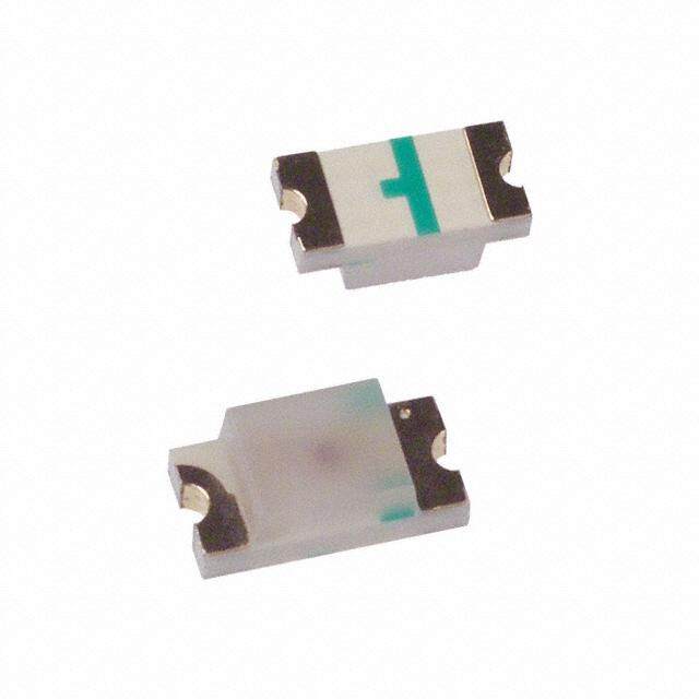
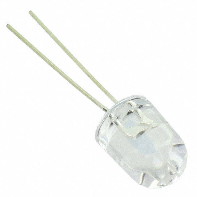
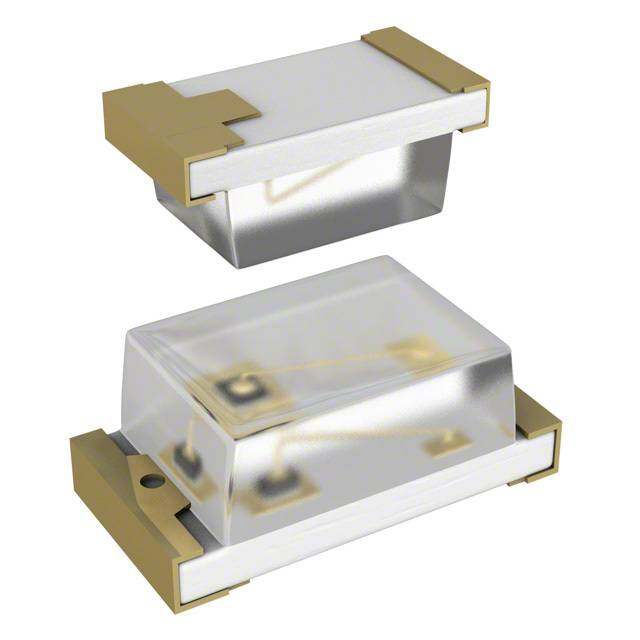
ICGOO电子元器件商城为您提供BR1102W-TR由Stanley Electric设计生产,在icgoo商城现货销售,并且可以通过原厂、代理商等渠道进行代购。 BR1102W-TR价格参考¥0.44-¥0.44。Stanley ElectricBR1102W-TR封装/规格:LED 指示 - 分立, 红色 647nm LED 指示 - 分立 1.7V 1206(3216 公制)。您可以下载BR1102W-TR参考资料、Datasheet数据手册功能说明书,资料中有BR1102W-TR 详细功能的应用电路图电压和使用方法及教程。
型号为BR1102W-TR的LED指示灯由Stanley Electric Co生产,属于“LED 指示 - 分立”类别。其应用场景主要包括以下几个方面:

1. 工业设备:该型号的LED指示灯广泛应用于各种工业设备中,如控制面板、操作按钮和状态显示装置。它能够清晰地指示设备的运行状态(如电源开启/关闭、报警等),帮助操作人员快速了解设备状况。

2. 家用电器:在家电领域,BR1102W-TR可用于冰箱、洗衣机、微波炉、空调等产品的状态提示功能。例如,用于显示电源开关、模式选择或故障报警等信息。

3. 汽车电子:尽管主要定位为通用型指示灯,但该型号也可用于汽车内部仪表盘或控制台中的辅助指示功能,例如灯光状态提示或系统警告灯。

4. 通信设备:在网络路由器、交换机或其他通信设备中,这种LED指示灯可以用来显示信号强度、连接状态或数据传输活动。

5. 消费电子产品:包括音响设备、遥控器、充电器等小型电子设备中,可作为电源指示或工作状态提示使用。

6. 医疗设备:在一些低功率需求的医疗仪器上,如监护仪、测量仪等,BR1102W-TR可以用作简单的状态指示灯。

特点方面,BR1102W-TR具有高亮度、低功耗和长寿命的优点,适合需要稳定可靠光源的应用场景。同时,其紧凑的设计便于集成到各种电路板或设备外壳中。
| 参数 | 数值 |
| 产品目录 | |
| 描述 | LED RED CLEAR 1206 SMD |
| 产品分类 | |
| 品牌 | Stanley Electric Co |
| 数据手册 | |
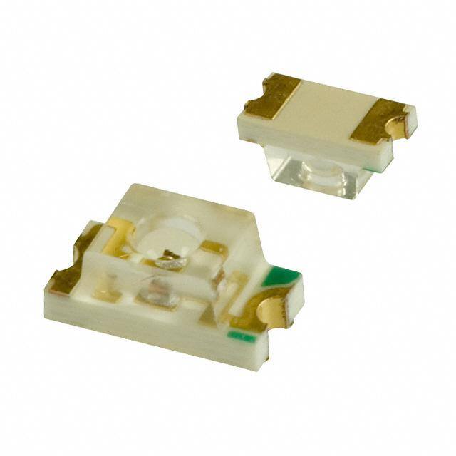
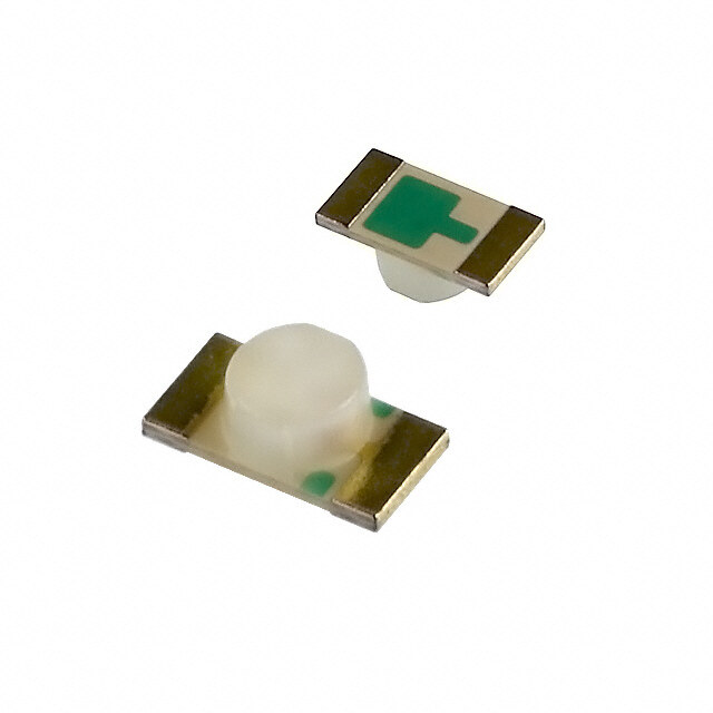
| 产品图片 |
|
| 产品型号 | BR1102W-TR |
| rohs | 无铅 / 符合限制有害物质指令(RoHS)规范要求 |
| 产品系列 | 1102W |
| 产品目录绘图 |
|
| 产品目录页面 | |
| 其它名称 | 404-1048-2 |
| 包装 | 带卷 (TR) |
| 大小/尺寸 | 3.00mm 长 x 1.50mm 宽 |
| 安装类型 | 表面贴装 |
| 封装/外壳 | 1206(3216 公制) |
| 标准包装 | 2,500 |
| 毫烛光等级 | 33.6mcd |
| 波长-主 | 647nm |
| 波长-峰值 | 660nm |
| 测试电流时的光通量 | - |
| 电压-正向(Vf)(典型值) | 1.7V |
| 电流-测试 | 20mA |
| 视角 | 70°, 82° |
| 透镜样式/尺寸 | 矩形,带平顶,2mm x 1.5mm |
| 透镜类型 | 透明 |
| 颜色 | 红 |
| 高度 | 1.90mm |


- 商务部:美国ITC正式对集成电路等产品启动337调查
- 曝三星4nm工艺存在良率问题 高通将骁龙8 Gen1或转产台积电
- 太阳诱电将投资9.5亿元在常州建新厂生产MLCC 预计2023年完工
- 英特尔发布欧洲新工厂建设计划 深化IDM 2.0 战略
- 台积电先进制程称霸业界 有大客户加持明年业绩稳了
- 达到5530亿美元!SIA预计今年全球半导体销售额将创下新高
- 英特尔拟将自动驾驶子公司Mobileye上市 估值或超500亿美元
- 三星加码芯片和SET,合并消费电子和移动部门,撤换高东真等 CEO
- 三星电子宣布重大人事变动 还合并消费电子和移动部门
- 海关总署:前11个月进口集成电路产品价值2.52万亿元 增长14.8%


PDF Datasheet 数据手册内容提取
1102W Series Single Color 3216 Type Features Package 3216 Type, Water Clear resin Product features Outer Dimension 3.0 x 1.5 x 1.5mm ( L x W x H ) Temperature range Storage Temperature : -40℃~100℃ Operating Temperature : -30℃~85℃ Lead–free soldering compatible RoHS compliant Dominant wavelength Green : 558nm(BG),567nm(PG) Yellow Green : 572nm(PY) Yellow : 590nm(AY) Orange : 606nm(AA) Red : 647nm(BR) Half Intensity Angle BG :θx= 56 deg., θy=71 deg. PG :θx= 69 deg., θy=85 deg. PY :θx= 61 deg., θy=71 deg. AY :θx= 70 deg., θy=89 deg. AA :θx= 77 deg., θy=87 deg. BR :θx= 70 deg., θy=82 deg. Die materials BG,PG,PY : GaP AY,AA : GaAsP BR : GaAlAs Rank grouping parameter Sorted by luminous intensity per rank taping Assembly method Auto pick & place machine (Auto Mounter) Soldering methods Reflow soldering and manual soldering 2,500pcs per reel in a 8mm width tape. (Standard) Taping and reel Reel diameter:φ180mm ESD More than 2kV(HBM) Recommended Applications Communication Machine, Electric Household Appliances, OA/FA, Amusement Equipment, Other General Applications 2007.8.31 Page 1
1102W Series Single Color 3216 Type Color and Luminous Intensity (Ta=25℃) Dominant Luminous Intensity Emitted Lens Wavelength Part No. Material Color Color λd (nm) Iv (mcd) TYP. I MIN. TYP. I F F BG1102W Gap Green 558 20 1.8 4.8 20 PG1102W Gap Green 567 20 6 12 20 Yellow PY1102W Gap 572 20 12 24 20 Green Water Clear AY1102W GaAsP Yellow 590 20 3 6 20 AA1102W GaAsP Orange 606 20 5 9 20 BR1102W GaAlAs Red 647 20 12 33.6 20 2004.10.29 Page 2
1102W Series Single Color 3216 Type Absolute Maximum Ratings (Ta=25℃) Absolute Maximum Ratings Item Symbol Unit BG PG PY AY AA BR Power Dissipation P 75 75 75 75 75 60 mW d Forward Current I 30 30 30 30 30 30 mA F Pulse Forward I 70 70 70 70 70 70 mA Current ※1 FRM ⊿I 0.42 0.42 0.42 0.42 0.42 0.42 mA/℃ Derating F (Ta=25℃ or higher) ⊿I 0.93 0.93 0.93 0.93 0.93 0.93 mA/℃ FRM Reverse Voltage V 4 4 4 4 4 4 V R Operating T -30~+85 ℃ Temperature opr Storage Temperature T -40~+100 ℃ stg ※1 I Measurementcondition : Pulse Width≦1ms., Duty≦1/20. FRM 2004.10.29 Page 3
1102W Series Single Color 3216 Type Electro-Optical Characteristics (Ta=25℃) Characteristics Item Symbol Unit Conditions BG PG PY AY AA BR TYP. 2.1 2.1 2.1 2.2 2.2 1.7 Forward Voltage I=20mA V V F F MAX. 2.5 2.5 2.5 2.5 2.5 2.0 Reverse Current V =4V I MAX. 100 100 100 100 100 100 μA R R Peak Wavelength I=20mA λ TYP. 555 560 570 580 605 660 nm F p Dominant I=20mA λ TYP. 558 567 572 590 606 647 nm Wavelength F d Spectral Line Half I=20mA ⊿λ TYP. 30 30 30 30 30 30 nm Width F 56(θx) 69(θx) 61(θx) 70(θx) 77(θx) 70(θx) Half Intensity Angle I=20mA 2θ1/2 TYP. deg. F 71(θy) 85(θy) 71(θy) 89(θy) 87(θy) 82(θy) 2004.10.29 Page 4
1102W Series Single Color 3216 Type Luminous Intensity Rank (Ta=25℃) I (mcd) V BG PG PY AY AA BR Rank I =20mA I =20mA I =20mA I =20mA I =20mA I =20mA F F F F F F MIN. MAX. MIN. MAX. MIN. MAX. MIN. MAX. MIN. MAX. MIN. MAX. A 3.0 6.0 5.0 10.0 B 4.2 8.4 7.0 14.0 C 1.8 3.6 6.0 12.0 12.0 24.0 6.0 12.0 10.0 20.0 12.0 24.0 D 2.4 4.8 8.5 17.0 16.8 33.6 8.4 16.8 14.0 28.0 16.8 33.6 E 3.6 7.2 12.0 24.0 24.0 48.0 12.0 - 20.0 - 24.0 48.0 F 4.8 9.6 17.0 34.0 33.6 67.2 33.6 67.2 G 7.2 - 24.0 - 48.0 - 48.0 - ※Please contact our sales staff concerning rank designation. 2004.10.29 Page 5
1102W Series Single Color 3216 Type Technical Data(BG) Spectral Distribution Spatial Distribution Example Relative Intensity vs. Wavelength Condition : Ta = 25℃, I = 20mA F Condition : Ta = 25℃ y sit n e nt e I v ati el R Wavelength[nm] Forward Voltage vs. Forward Current Forward Current vs. Relative Intensity Condition : Ta = 25℃ Condition : Ta = 25℃ A) m nt I(F sity urre nten d C ve I orwar Relati F Forward Voltage V(V) Forward Current I(mA) F F 2004.10.29 Page 6
1102W Series Single Color 3216 Type Technical Data(BG) Derating Ambient Temperature vs. Relative Intensity Ambient Temperature vs. Maximum Forward Current Condition : I=20mA F Repetition Frequency : f ≧50Hz A) m X. ( A M nt : IF nsity e e d Curr ve Int war ati For Rel m u m xi a M Ambient Temperature : Ta(℃) Ambient Temperature : Ta(℃) Power Dissipation vs. Ambient Temperature Pulse Width vs. Maximum Tolerable Peak Current Condition : Ta = 25℃ W) m Pd ( X. n : MA o C ati D Dissip Max./IF wer eak o p P IF Ambient Temperature : Ta(℃) Pulse Width : tw(μs) 2004.10.29 Page 7
1102W Series Single Color 3216 Type Technical Data(PG) Spectral Distribution Spatial Distribution Example Relative Intensity vs. Wavelength Condition : Ta = 25℃, I = 20mA F Condition : Ta = 25℃ y sit n e nt e I v ati el R Wavelength[nm] Forward Voltage vs. Forward Current Forward Current vs. Relative Intensity Condition : Ta = 25℃ Condition : Ta = 25℃ A) m nt I(F sity urre nten d C ve I orwar Relati F Forward Voltage V(V) Forward Current I(mA) F F 2004.10.29 Page 8
1102W Series Single Color 3216 Type Technical Data(PG) Derating Ambient Temperature vs. Relative Intensity Ambient Temperature vs. Maximum Forward Current Condition : I=20mA F Repetition Frequency : f ≧50Hz A) m X. ( A M nt : IF nsity e e d Curr ve Int war ati For Rel m u m xi a M Ambient Temperature : Ta(℃) Ambient Temperature : Ta(℃) Power Dissipation vs. Ambient Temperature Pulse Width vs. Maximum Tolerable Peak Current Condition : Ta = 25℃ W) m Pd ( X. n : MA o C ati D Dissip Max./IF wer eak o p P IF Ambient Temperature : Ta(℃) Pulse Width : tw(μs) 2004.10.29 Page 9
1102W Series Single Color 3216 Type Technical Data(PY) Spectral Distribution Spatial Distribution Example Relative Intensity vs. Wavelength Condition : Ta = 25℃, I = 20mA F Condition : Ta = 25℃ y sit n e nt e I v ati el R Wavelength[nm] Forward Voltage vs. Forward Current Forward Current vs. Relative Intensity Condition : Ta = 25℃ Condition : Ta = 25℃ A) m nt I(F sity urre nten d C ve I orwar Relati F Forward Voltage V(V) Forward Current I(mA) F F 2004.10.29 Page 10
1102W Series Single Color 3216 Type Technical Data(PY) Derating Ambient Temperature vs. Relative Intensity Ambient Temperature vs. Maximum Forward Current Condition : I=20mA F Repetition Frequency : f ≧50Hz A) m X. ( A M nt : IF nsity e e d Curr ve Int war ati For Rel m u m xi a M Ambient Temperature : Ta(℃) Ambient Temperature : Ta(℃) Power Dissipation vs. Ambient Temperature Pulse Width vs. Maximum Tolerable Peak Current Condition : Ta = 25℃ W) m Pd ( X. n : MA o C ati D Dissip Max./IF wer eak o p P IF Ambient Temperature : Ta(℃) Pulse Width : tw(μs) 2004.10.29 Page 11
1102W Series Single Color 3216 Type Technical Data(AY) Spectral Distribution Spatial Distribution Example Relative Intensity vs. Wavelength Condition : Ta = 25℃, I = 20mA F Condition : Ta = 25℃ y sit n e nt e I v ati el R Wavelength[nm] Forward Voltage vs. Forward Current Forward Current vs. Relative Intensity Condition : Ta = 25℃ Condition : Ta = 25℃ A) m nt I(F sity urre nten d C ve I orwar Relati F Forward Voltage V(V) Forward Current I(mA) F F 2004.10.29 Page 12
1102W Series Single Color 3216 Type Technical Data(AY) Derating Ambient Temperature vs. Relative Intensity Ambient Temperature vs. Maximum Forward Current Condition : I=20mA F Repetition Frequency : f ≧50Hz A) m X. ( A M nt : IF nsity e e d Curr ve Int war ati For Rel m u m xi a M Ambient Temperature : Ta(℃) Ambient Temperature : Ta(℃) Power Dissipation vs. Ambient Temperature Pulse Width vs. Maximum Tolerable Peak Current Condition : Ta = 25℃ W) m Pd ( X. n : MA o C ati D Dissip Max./IF wer eak o p P IF Ambient Temperature : Ta(℃) Pulse Width : tw(μs) 2004.10.29 Page 13
1102W Series Single Color 3216 Type Technical Data(AA) Spectral Distribution Spatial Distribution Example Relative Intensity vs. Wavelength Condition : Ta = 25℃, I = 20mA F Condition : Ta = 25℃ y sit n e nt e I v ati el R Wavelength[nm] Forward Voltage vs. Forward Current Forward Current vs. Relative Intensity Condition : Ta = 25℃ Condition : Ta = 25℃ A) m nt I(F sity urre nten d C ve I orwar Relati F Forward Voltage V(V) Forward Current I(mA) F F 2004.10.29 Page 14
1102W Series Single Color 3216 Type Technical Data(AA) Derating Ambient Temperature vs. Relative Intensity Ambient Temperature vs. Maximum Forward Current Condition : I=20mA F Repetition Frequency : f ≧50Hz A) m X. ( A M nt : IF nsity e e d Curr ve Int war ati For Rel m u m xi a M Ambient Temperature : Ta(℃) Ambient Temperature : Ta(℃) Power Dissipation vs. Ambient Temperature Pulse Width vs. Maximum Tolerable Peak Current Condition : Ta = 25℃ W) m Pd ( X. n : MA o C ati D Dissip Max./IF wer eak o p P IF Ambient Temperature : Ta(℃) Pulse Width : tw(μs) 2004.10.29 Page 15
1102W Series Single Color 3216 Type Technical Data(BR) Spectral Distribution Spatial Distribution Example Relative Intensity vs. Wavelength Condition : Ta = 25℃, I = 20mA F Condition : Ta = 25℃ y sit n e nt e I v ati el R Wavelength[nm] Forward Voltage vs. Forward Current Forward Current vs. Relative Intensity Condition : Ta = 25℃ Condition : Ta = 25℃ A) m nt I(F sity urre nten d C ve I orwar Relati F Forward Voltage V(V) Forward Current I(mA) F F 2004.12.15 Page 16
1102W Series Single Color 3216 Type Technical Data(BR) Derating Ambient Temperature vs. Relative Intensity Ambient Temperature vs. Maximum Forward Current Condition : I=20mA F Repetition Frequency : f ≧50Hz A) m X. ( A M nt : IF nsity e e d Curr ve Int war ati For Rel m u m xi a M Ambient Temperature : Ta(℃) Ambient Temperature : Ta(℃) Power Dissipation vs. Ambient Temperature Pulse Width vs. Maximum Tolerable Peak Current Condition : Ta = 25℃ W) m Pd ( X. n : MA o C ati D Dissip Max./IF wer eak o p P IF Ambient Temperature : Ta(℃) Pulse Width : tw(μs) 2004.10.29 Page 17
1102W Series Single Color 3216 Type Package Dimensions (Unit: mm) Weight: (7.80)mg Recommended Soldering Pattern (Unit: mm) Taping Specification (Unit: mm) Quantity : 2,500pcs/ reel (standard) 2004.10.29 Page 18
1102W Series Single Color 3216 Type Reflow Soldering Conditions 1) The above profile temperature gives the maximum temperature of the LED resin surface. Please set the temperature so as to avoid exceeding this range. 2) Total times of reflow soldering process shall be no more than 2 times. When the second reflow soldering process is performed, intervals between the first and second reflow should be short as possible (while allowing some time for the component to return to normal temperature after the first reflow) in order to prevent the LED from absorbing moisture. 3) Temperature fluctuation to the LED during the pre-heating process shall be minimized. (6℃maximum) Manual Soldering Conditions Iron tip temp. 350 ℃ (MAX.) Soldering time and frequency 3 s (MAX.) 1 time (MAX.) 2007.8.31 Page 19
1102W Series Single Color 3216 Type Reliability Testing Result Reliability Testing Applicable Standard Testing Conditions Duration Failure Result Room Temp. EIAJ ED- Operating Life 4701/100(101) Ta = 25℃, IF = Maxium Rated Current 1,000 h 0/25 Pre-heating : 150~180℃ 120s Max. Resistance to EIAJ ED- Operation Heating : 230℃ 40s Max. Twice 0/25 Soldering Heat 4701/300(301) Peak Temperature : 260℃ Minimum Rated Storage Temperature(30min) EIAJ ED- ~Normal Temperature(15min) Temperature Cycling 5 cycles 0/25 4701/100(105) ~Maximum Rated Storage Temperature(30min) ~Normal Temperature(15min) Wet High Temp. EIAJ ED- Ta = 60±2℃, RH = 90±5% 1,000 h 0/25 Storage Life 4701/100(103) High Temp. EIAJ ED- Ta = Maximum Rated Storage Temperature 1,000 h 0/25 Storage Life 4701/200(201) Low Temp. EIAJ ED- Ta = Minimum Rated Storage Temperature 1,000 h 0/25 Storage Life 4701/200(202) Vibration, EIAJ ED- 98.1m/s2 (10G), 100 ~ 2KHz sweep for 20min., 2 h 0/10 Variable Frequency 4701/400(403) XYZ each direction Failure Criteria Items Symbols Conditions Failure criteria IF Value of each product Luminous Intensity Iv Testing Min. Value < Spec. Min. Value x 0.5 Luminous Intensity IF Value of each product Forward Voltage VF Testing Max. Value ≧ Spec. Max. Value x 1.2 Forward Voltage VR = Maximum Rated Reverse Current IR Testing Max. Value ≧ Spec. Max. Value x 2.5 Reverse Voltage V Occurrence of notable decoloration, Cosmetic Appearance - - deformation and cracking 2007.8.31 Page 20
1102W Series Single Color 3216 Type Special Notice to Customers Using the Products and Technical Information Shown in This Data Sheet 1) The technical information shown in the data sheets are limited to the typical characteristics and circuit examples of the referenced products. It does not constitute the warranting of industrial property nor the granting of any license. 2) For the purpose of product improvement, the specifications, characteristics and technical data described in the data sheets are subject to change without prior notice. Therefore it is recommended that the most updated specifications be used in your design. 3) When using the products described in the data sheets, pleaseadhere to the maximum ratings for operating voltage, heat dissipation characteristics, and other precautions for use. We are not responsible for any damage which may occur if these specifications are exceeded. 4) The products that have been described to this catalog are manufactured so that they will be used for the electrical instrument of the benchmark (OA equipment, telecommunications equipment, AV machine, home appliance and measuring instrument). The application of aircrafts, space borne application, transportation equipment, medical equipment and nuclear power control equipment, etc. needs a high reliability and safety, and the breakdown and the wrong operation might influence the life or the human body. Please consult us beforehand if you plan to use our product for the usages of aircrafts, space borne application, transportation equipment, medical equipment and nuclear power control equipment, etc. except OA equipment, telecommunications equipment, AV machine, home appliance and measuring instrument. 5) In order to export the products or technologies described inthis data sheet which are under the “Foreign Exchange and Foreign Trade Control Law,”it is necessary to first obtain an export permit from the Japanese government. 6) No part of this data sheet may be reprinted or reproduced without prior written permission from Stanley Electric Co., Ltd. 7) The most updated edition of this data sheet can be obtained from the address below: http://www.stanley-components.com 2007.8.31 Page 21