 Datasheet下载
- 型号: BFC238350163
- 制造商: Vishay
- 库位|库存: xxxx|xxxx
- 要求:
| 数量阶梯 | 香港交货 | 国内含税 |
| +xxxx | $xxxx | ¥xxxx |
查看当月历史价格
查看今年历史价格
BFC238350163产品简介:
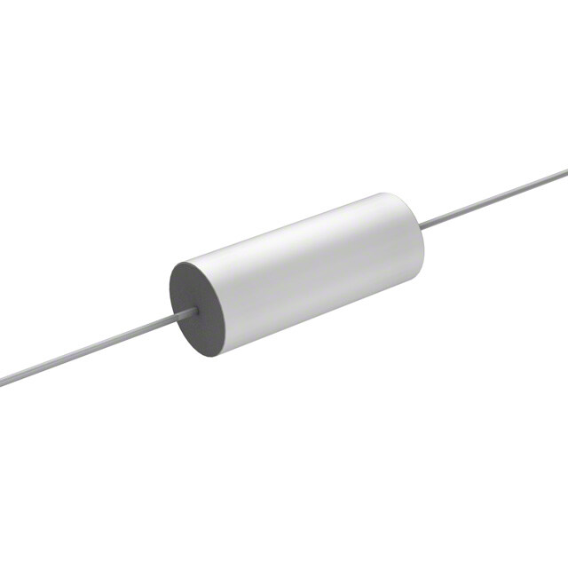
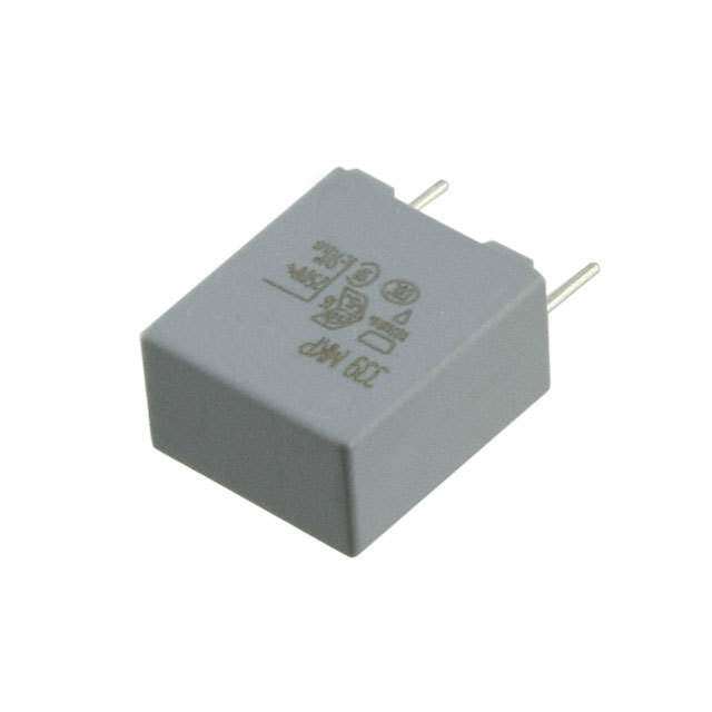
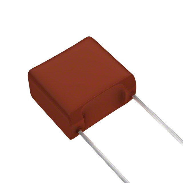
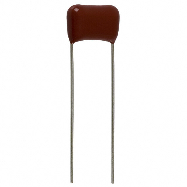
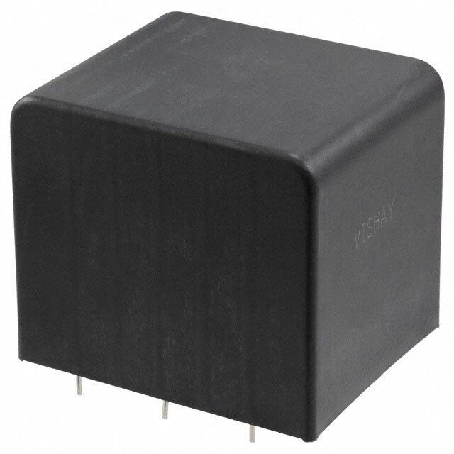
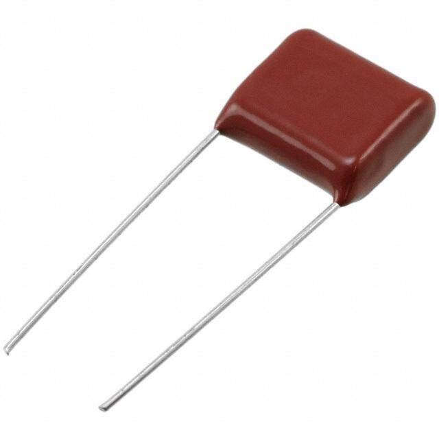
ICGOO电子元器件商城为您提供BFC238350163由Vishay设计生产,在icgoo商城现货销售,并且可以通过原厂、代理商等渠道进行代购。 BFC238350163价格参考¥19.73-¥46.77。VishayBFC238350163封装/规格:薄膜电容器, 0.016µF 薄膜电容器 550V 1600V(1.6kV) 聚丙烯(PP),金属化 径向。您可以下载BFC238350163参考资料、Datasheet数据手册功能说明书,资料中有BFC238350163 详细功能的应用电路图电压和使用方法及教程。
Vishay BC Components的BFC238350163是一款薄膜电容器,广泛应用于需要高稳定性和可靠性的场景。以下是其主要应用场景:

1. 电源电路:该型号适合用于开关电源(SMPS)中的输入/输出滤波器,能够有效抑制电磁干扰(EMI),确保电源系统的稳定性。

2. 逆变器和变频器:在工业控制领域,BFC238350163可用于逆变器和变频器的直流母线支撑、耦合或解耦应用,支持高效能量转换并减少纹波电流的影响。

3. 电机驱动:适用于电机驱动系统中的滤波与缓冲功能,帮助降低噪声干扰,提高运行效率及设备寿命。

4. 音频设备:在高端音响设备中作为耦合或旁路电容使用,提供清晰纯净的声音表现,避免信号失真。

5. 汽车电子:满足现代汽车电气化需求,在车载充电器、LED照明驱动以及发动机管理模块等部位发挥重要作用,适应苛刻的工作环境。

6. 医疗仪器:用于精密医疗器械内,例如心电图机、超声波诊断装置等,保障测量结果准确无误。

7. 通信设施:服务于基站、路由器等通讯设备,执行信号调理任务,增强数据传输质量。

由于其具备优良的耐压性能、低损耗特性和宽温工作范围,这款电容器特别适合那些对尺寸敏感但又要求高性能表现的应用场合。
| 参数 | 数值 |
| 产品目录 | |
| 描述 | CAP FILM 0.016UF 1.6KVDC RADIAL薄膜电容器 .016uF 5% 1600volts |
| ESR(等效串联电阻) | - |
| 产品分类 | |
| 品牌 | Vishay / BC ComponentsVishay BC Components |
| 产品手册 | |
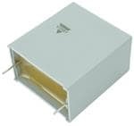
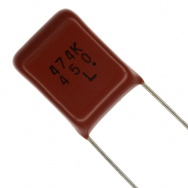
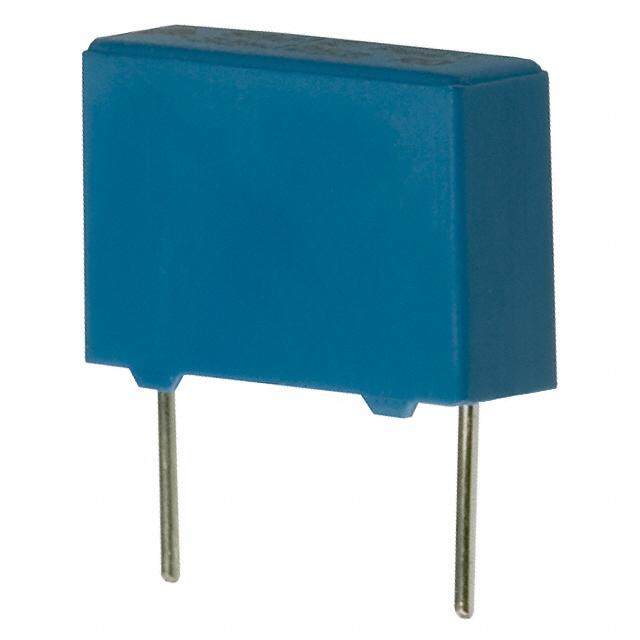
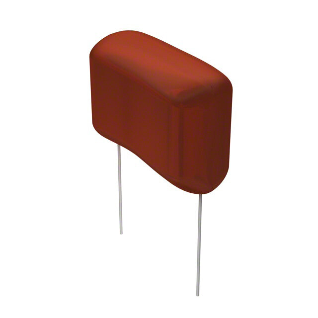
| 产品图片 |
|
| rohs | 符合RoHS无铅 / 符合限制有害物质指令(RoHS)规范要求 |
| 产品系列 | 薄膜电容器,Vishay / BC Components BFC238350163383 |
| 数据手册 | |
| 产品型号 | BFC238350163BFC238350163 |
| 产品 | AC and Pulse Film Capacitors |
| 产品培训模块 | http://www.digikey.cn/PTM/IndividualPTM.page?site=cn&lang=zhs&ptm=24930 |
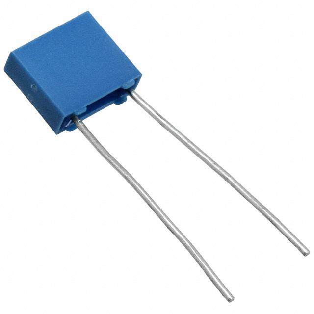
| 产品目录绘图 |
|
| 产品目录页面 | |
| 产品种类 | |
| 介电材料 | 聚丙烯(PP), 金属化 |
| 其它名称 | 2222 383 50163 |
| 包装 | 散装 |
| 商标 | Vishay / BC Components |
| 大小/尺寸 | 1.024" 长 x 0.276" 宽(26.00mm x 7.00mm) |
| 安装类型 | 通孔 |
| 容差 | ±5%5 % |
| 封装/外壳 | 径向 |
| 工作温度 | -55°C ~ 105°C |
| 工厂包装数量 | 200 |
| 应用 | 高脉冲,DV/DT |
| 引线间距 | 0.886"(22.50mm) |
| 引线间隔 | 22.5 mm |
| 最大工作温度 | + 105 C |
| 最小工作温度 | - 55 C |
| 标准包装 | 200 |
| 特性 | - |
| 电介质 | Polypropylene (PP) |
| 电压额定值AC | 550 V |
| 电压额定值DC | 1.6 kV |
| 电容 | 0.016µF0.016 uF |
| 端接 | PC 引脚 |
| 端接类型 | Radial |
| 类型 | Radial Potted Capacitor |
| 系列 | MMKP |
| 零件号别名 | 222238350163 |
| 额定电压-AC | 550V |
| 额定电压-DC | 1600V(1.6kV) |
| 高度-安装(最大值) | 0.650"(16.50mm) |


- 商务部:美国ITC正式对集成电路等产品启动337调查
- 曝三星4nm工艺存在良率问题 高通将骁龙8 Gen1或转产台积电
- 太阳诱电将投资9.5亿元在常州建新厂生产MLCC 预计2023年完工
- 英特尔发布欧洲新工厂建设计划 深化IDM 2.0 战略
- 台积电先进制程称霸业界 有大客户加持明年业绩稳了
- 达到5530亿美元!SIA预计今年全球半导体销售额将创下新高
- 英特尔拟将自动驾驶子公司Mobileye上市 估值或超500亿美元
- 三星加码芯片和SET,合并消费电子和移动部门,撤换高东真等 CEO
- 三星电子宣布重大人事变动 还合并消费电子和移动部门
- 海关总署:前11个月进口集成电路产品价值2.52万亿元 增长14.8%

PDF Datasheet 数据手册内容提取
MKP383 www.vishay.com Vishay BCcomponents AC and Pulse Double Metallized Polypropylene Film Capacitors MKP Radial Potted Type FEATURES • 7.5 mm to 37.5 mm lead pitch; 7.5 mm bent back pitch • Low contact resistance • Low loss dielectric • Small dimensions for high density packaging • Supplied loose in box and taped on reel or ammopack • Mounting: radial • Material categorization: for definitions of compliance please see www.vishay.com/doc?99912 APPLICATIONS • Where steep pulses occur e.g. SMPS (switch mode power supplies) • Electronic lighting e.g. ballast • Motor control circuits • S-correction • For flyback applications please use 1400 V series QUICK REFERENCE DATA Capacitance range (E24 series) 0.00047 μF to 4.7 μF Capacitance tolerance ± 5 % Climatic testing class according to IEC 60068-1 55/105/56 Rated DC temperature 85 °C Rated AC temperature 105 °C Maximum application temperature 105 °C Reference specifications IEC 60384-17 Dielectric Polypropylene film Electrodes Metallized Construction Mono and internal serial construction Flame retardant plastic case and epoxy resin Encapsulation UL-class 94 V-0 Leads Tinned wire C-value; tolerance; rated voltage; sub-class; manufacturer’s type; code for dielectric Marking material; manufacturer location; manufacturer's logo; year and week Note • For more detailed data and test requirements, contact dc-film@vishay.com VOLTAGE RATINGS Rated DC voltage 250 400 630 1000 1400 1600 2000 2500 Rated AC voltage 125 200 220 350 500 550 700 900 Rated peak to peak voltage 350 560 630 1000 1400 1600 2000 2500 Revision: 08-Aug-2018 1 Document Number: 28173 For technical questions, contact: dc-film@vishay.com THIS DOCUMENT IS SUBJECT TO CHANGE WITHOUT NOTICE. THE PRODUCTS DESCRIBED HEREIN AND THIS DOCUMENT ARE SUBJECT TO SPECIFIC DISCLAIMERS, SET FORTH AT www.vishay.com/doc?91000
MKP383 www.vishay.com Vishay BCcomponents COMPOSITION OF CATALOG NUMBER Voltage (V ) P (mm) Pitch Code DC 1 Example 025 = 250 5 B 147 470 pF 0.00047 μF 040 = 400 7.5 C 210 1 nF 0.001 μF 063 = 630 10 D 310 10 nF 0.01 μF 100 = 1000 15 F 410 100 nF 0.1 μF 140 = 1400 22.5 I 510 1000 nF 1.0 μF 160 = 1600 27.5 K 610 10 000 nF 10.0 μF Multiplier (nF) 200 = 2000 37.5 P 250 = 2500 0.01 1 0.1 2 Capacitance Code Special Code for Terminal 1 3 (numerically) 2 2 pins 10 4 4 4 pins P = 10.2 mm 100 5 2 5 4 pins P = 20.3 mm 1000 6 2 (#) Customized 1 2 3 4 5 6 7 8 9 10 11 12 13 14 15 16 17 18 M K P 3 8 3 1 4 7 2 5 0 J I P 2 T 0 Special 0 = Standard Type Tolerance Other = Special J ± 5 % A Special tolerance It (mm) Lead Length Code Pitch (mm) Packing Code Packing Style Remark 3.5 + 1.0/- 0.5 A ≤ 10 B/T Bulk/loose (1) Excluding bent back 3.5 ± 0.3 P ≥ 15 R Tape and reel; (H: 16.0 mm; 500 mm) For bent back only 5 ± 1 M All Z Tape and reel; (H: 16.0 mm; 356 mm) For bent back only 25 ± 2 I All H Ammo (H: 16.0 mm) For bent back only 0: Space holder W Tape and reel (H: 18.5 mm; 500 mm) Pitch 5 mm to 22.5 mm G Ammo (H: 18.5 mm) Pitch ≤ 10 mm Notes • For detailed tape specifications refer to packaging information www.vishay.com/doc?28139 (1) Packaging will be bulk for all capacitors with pitch 15 mm and such with long leads (> 5 mm). Capacitors with short leads up to 5 mm and pitch > 15 mm will be in tray and asking code will be “T”. Revision: 08-Aug-2018 2 Document Number: 28173 For technical questions, contact: dc-film@vishay.com THIS DOCUMENT IS SUBJECT TO CHANGE WITHOUT NOTICE. THE PRODUCTS DESCRIBED HEREIN AND THIS DOCUMENT ARE SUBJECT TO SPECIFIC DISCLAIMERS, SET FORTH AT www.vishay.com/doc?91000
MKP383 www.vishay.com Vishay BCcomponents ELECTRICAL DATA (For Detailed Ratings go to www.vishay.com/doc?28183) U CAP. RDC (V) (μF) 0.0068 min. 250 2.7 max. 0.0047 min. 400 1.5 max. 0.00047 min. 630 4.7 max. 0.0043 min. 1000 1.8 max. 0.0022 min. 1400 0.68 max. 0.0027 min. 1600 0.56 max. 0.0010 min. 2000 0.56 max. 0.0010 min. 2500 0.3 max. DIMENSIONS in millimeters l w l w h h h' F' lt (1) Ø dt F H P 10 Ø dt 15 I w Marking h Ø d 6 -2 t P ± 0.5 P ± 0.5 1 2 Note (1) | F-F' | < 0.3 mm F = 7.5 mm + 0.6 mm / - 0.1 mm Ø dt ± 10 % of standard diameter specified Revision: 08-Aug-2018 3 Document Number: 28173 For technical questions, contact: dc-film@vishay.com THIS DOCUMENT IS SUBJECT TO CHANGE WITHOUT NOTICE. THE PRODUCTS DESCRIBED HEREIN AND THIS DOCUMENT ARE SUBJECT TO SPECIFIC DISCLAIMERS, SET FORTH AT www.vishay.com/doc?91000
MKP383 www.vishay.com Vishay BCcomponents MOUNTING Normal Use The capacitors are designed for mounting on printed-circuit boards. The capacitors packed in bandoliers are designed for mounting on printed-circuit boards by means of automatic insertion machines. For detailed tape specifications refer to packaging information www.vishay.com/doc?28139 Specific Method of Mounting to Withstand Vibration and Shock In order to withstand vibration and shock tests, it must be ensured that the stand-off pips are in good contact with the printed-circuit board: • For original pitch = 15 mm the capacitors shall be mechanically fixed by the leads • For larger pitches the capacitors shall be mounted in the same way and the body clamped Space Requirements on Printed-Circuit Board The maximum space for length (l ), width (w ) and height (h ) of film capacitors to take in account on the printed circuit max. max. max. board is shown in the drawings. For products with pitch 15 mm, w = l = 0.3 mm and h = 0.1 mm For products with 15 mm < pitch 27.5 mm, w =l = 0.5 mm and h = 0.1 mm For products with pitch = 37.5 mm, w = l = 0.7 mm and h = 0.5 mm Eccentricity as in drawing. The maximum eccentricity is smaller than or equal to the lead diameter of the product concerned. w = w + Δw max. Eccentricity Imax. = I + ΔI hmax. = h + Δh Seating plane SOLDERING CONDITIONS For general soldering conditions and wave soldering profile we refer to the document “Soldering Guidelines for Film Capacitors”: www.vishay.com/doc?28171 STORAGE TEMPERATURE T = -25 °C to +35 °C with RH maximum 75 % without condensation stg RATINGS AND CHARACTERISTICS REFERENCE CONDITIONS Unless otherwise specified, all electrical values apply to an ambient free temperature of 23 °C ± 1 °C, an atmospheric pressure of 86 kPa to 106 kPa and a relative humidity of 50 % ± 2 %. For reference testing, a conditioning period shall be applied over 96 h ± 4 h by heating the products in a circulating air oven at the rated temperature and a relative humidity not exceeding 20 %. Revision: 08-Aug-2018 4 Document Number: 28173 For technical questions, contact: dc-film@vishay.com THIS DOCUMENT IS SUBJECT TO CHANGE WITHOUT NOTICE. THE PRODUCTS DESCRIBED HEREIN AND THIS DOCUMENT ARE SUBJECT TO SPECIFIC DISCLAIMERS, SET FORTH AT www.vishay.com/doc?91000
MKP383 www.vishay.com Vishay BCcomponents CHARACTERISTICS 4 ce103 Δ C/C (%)2 typical 1 kHz mpedanΩ()102 I 0 max. 101 1 nF 100 100 nF - 2 2.2 µF 10-1 4.7 µF - 4 10-2 min. - 6 10-3 - 60 - 20 20 60 Tamb (°C)100 104 105 106 107 f (Hz) 108 Capacitance as a function of ambient temperature (typical curve) Impedance as a function of frequency (typical curve) (1 kHz) 1.2 or ct a f1.0 0.8 0.6 0.4 0.2 0.0 - 50 - 20 20 60 100 Tamb (°C) Max. DC and AC voltage as a function of temperature 103 103 Tamb ≤ 85 °C, 250 VDC 85 °C < Tamb ≤ 105 °C, 250 VDC e e g g a a oltV) oltV) AC v ( 100 nF AC v ( 220 nF 100 nF 102 470 nF 102 220 nF 1.0 μF 470 nF 2.2 μF 1.0 μF 2.2 μF 101 101 103 104 105 106 f (Hz) 107 102 103 104 105 106 f (Hz) 107 Max. RMS voltage as a function of frequency Max. RMS voltage as a function of frequency Revision: 08-Aug-2018 5 Document Number: 28173 For technical questions, contact: dc-film@vishay.com THIS DOCUMENT IS SUBJECT TO CHANGE WITHOUT NOTICE. THE PRODUCTS DESCRIBED HEREIN AND THIS DOCUMENT ARE SUBJECT TO SPECIFIC DISCLAIMERS, SET FORTH AT www.vishay.com/doc?91000
MKP383 www.vishay.com Vishay BCcomponents 103 103 Tamb ≤ 85 °C, 400 VDC 85 °C < Tamb ≤ 105 °C, 400 VDC e e g g a a oltV) oltV) AC v ( AC v ( 47 nF 47 nF 100 nF 100 nF 102 470 nF 102 470 nF 1.0 μF 1.0 μF 101 101 103 104 105 106 f (Hz) 107 102 103 104 105 106 f (Hz) 107 Max. RMS voltage as a function of frequency Max. RMS voltage as a function of frequency 103 103 Tamb ≤ 85 °C, 630 VDC 85 °C < Tamb ≤ 105 °C, 630 VDC e e g g a a oltV) oltV) AC v ( 10407 nnFF AC v ( 10407 nnFF 220 nF 220 nF 102 470 nF 102 470 nF 1.0 μF 1.0 μF 4.7 μF 4.7 μF 101 101 103 104 105 106 f (Hz) 107 102 103 104 105 106 f (Hz) 107 Max. RMS voltage as a function of frequency Max. RMS voltage as a function of frequency 103 103 Tamb ≤ 85 °C, 1000 VDC 85 °C < Tamb ≤ 105 °C, 1000 VDC e e g g a a oltV) oltV) AC v ( 41.07 nnFF AC v ( 4.7 nF 47 nF 10 nF 102 220 nF 102 47 nF 1.0 μF 220 nF 1.0 μF 101 101 103 104 105 106 f (Hz) 107 102 103 104 105 106 f (Hz) 107 Max. RMS voltage as a function of frequency Max. RMS voltage as a function of frequency Revision: 08-Aug-2018 6 Document Number: 28173 For technical questions, contact: dc-film@vishay.com THIS DOCUMENT IS SUBJECT TO CHANGE WITHOUT NOTICE. THE PRODUCTS DESCRIBED HEREIN AND THIS DOCUMENT ARE SUBJECT TO SPECIFIC DISCLAIMERS, SET FORTH AT www.vishay.com/doc?91000
MKP383 www.vishay.com Vishay BCcomponents 103 103 Tamb ≤ 85 °C, 1400 VDC 85 °C < Tamb ≤ 105 °C, 1400 VDC e e g g a a AC volt (V) 242..227 nnnFFF AC volt (V) 242..227 nnnFFF 100 nF 100 nF 102 470 nF 102 470 nF 101 101 103 104 105 106 f (Hz) 107 102 103 104 105 106 f (Hz) 107 Max. RMS voltage as a function of frequency Max. RMS voltage as a function of frequency 103 103 Tamb ≤ 85 °C, 1600 VDC 85 °C < Tamb ≤ 105 °C, 1600 VDC e e g g a a AC volt (V) 414.077 nnnFFF AC volt (V) 414.077 nnnFFF 100 nF 100 nF 102 470 nF 102 470 nF 101 101 103 104 105 106 f (Hz) 107 102 103 104 105 106 f (Hz) 107 Max. RMS voltage as a function of frequency Max. RMS voltage as a function of frequency 103 103 85 °C < T ≤ 105 °C, 2000 V amb DC e e g g AC volta (V) 214.1207 nnnnFFFF AC volta (V) 214.1072 nnnnFFFF 100 nF 100 nF 102 470 nF 102 470 nF T ≤ 85 °C, 2000 V amb DC 101 101 103 104 105 106 f (Hz) 107 102 103 104 105 106 f (Hz) 107 Max. RMS voltage as a function of frequency Max. RMS voltage as a function of frequency Revision: 08-Aug-2018 7 Document Number: 28173 For technical questions, contact: dc-film@vishay.com THIS DOCUMENT IS SUBJECT TO CHANGE WITHOUT NOTICE. THE PRODUCTS DESCRIBED HEREIN AND THIS DOCUMENT ARE SUBJECT TO SPECIFIC DISCLAIMERS, SET FORTH AT www.vishay.com/doc?91000
MKP383 www.vishay.com Vishay BCcomponents 103 103 AC voltage (V) 241..1270 nnnnFFFF AC voltage (V) 241..1270 nnnnFFFF 22 nF 22 nF 102 220 nF 102 220 nF T ≤ 85 °C, 2500 V amb DC 85 °C < T ≤ 105 °C, 2500 V amb DC 101 101 103 104 105 106 107 f (Hz) 108 102 103 104 105 106 f (Hz) 107 Max. RMS voltage as a function of frequency Max. RMS voltage as a function of frequency 106 12 C) s) T (° C ( Δ R 8 105 4 104 0 0 20 40 60 80 100 - 50 - 20 20 60 T (°C)100 T (°C) amb amb Insulation resistance as a function of the ambient temperature Maximum allowed component temperature rise (T) as a function of the ambient temperature (T ) amb Revision: 08-Aug-2018 8 Document Number: 28173 For technical questions, contact: dc-film@vishay.com THIS DOCUMENT IS SUBJECT TO CHANGE WITHOUT NOTICE. THE PRODUCTS DESCRIBED HEREIN AND THIS DOCUMENT ARE SUBJECT TO SPECIFIC DISCLAIMERS, SET FORTH AT www.vishay.com/doc?91000
MKP383 www.vishay.com Vishay BCcomponents 1000 4) -0 1 x 16 or ( 141153 ation fact 100 21110987 1119210 876543 p 2 ssi 21 1 Di 10 1 102 103 104 105 106 f (Hz) Tangent of loss angle as a function of frequency (typical curve) 250 V: 400 V: 630 V: 1000 V: 0.0068 C 0.091 μF, curve 8 0.0047 < C 0.047 μF, curve 5 0.00047 < C 0.033 μF, curve 4 C 0.01 μF, curve 2 0.1 < C 0.15 μF, curve 9 0.047 < C 0.068 μF, curve 6 0.033 < C 0.068 μF, curve 5 0.011 < C 0.027 μF, curve 3 0.15 < C 0.22 μF, curve 10 0.068 < C 0.1 μF, curve 7 0.068 < C 0.1 μF, curve 6 0.027 < C 0.047 μF, curve 4 0.22 < C 0.27 μF, curve 11 0.1 < C 0.2 μF, curve 8 0.1 < C 0.15 μF, curve 7 0.047 < C 0.062 μF, curve 5 0.27 < C 0.33 μF, curve 12 0.2 < C 0.24 μF, curve 12 0.15 < C 0.22 μF, curve 11 0.062 < C 0.075 μF, curve 6 0.33 < C 0.56 μF, curve 15 0.24 < C 0.36 μF, curve 13 0.22 < C 0.27 μF, curve 12 0.075 < C 0.1 μF, curve 7 0.56 < C 0.82 μF, curve 16 0.36 < C 0.43 μF, curve 14 0.27 < C 0.33 μF, curve 15 0.1 < C 0.15 μF, curve 8 0.82 < C 1.2 μF, curve 18 0.43 < C 0.56 μF, curve 16 0.33 < C 0.82 μF, curve 16 0.15 < C 0.22 μF, curve 9 1.2 < C 1.6 μF, curve 19 0.56 < C 1.1 μF, curve 17 0.82 < C 1 μF, curve 18 0.22 < C 0.3 μF, curve 10 1.6 < C 2.7 μF, curve 20 1.1 < C 1.5 μF, curve 18 1 < C 4.7 μF, curve 21 0.3 < C 1 μF, curve 16 1 < C 1.8 μF, curve 19 1400 V: 1600 V: 2000 V: 2500 V: C 0.0047 μF, curve 1 C 0.0047 μF, curve 3 C 0.0047 μF, curve 2 C 0.0047 μF, curve 1 0.0051 < C 0.016 μF, curve 2 0.0051 < C 0.0091 μF, curve 4 0.0051 < C 0.033 μF, curve 3 0.0051 < C 0.015 μF, curve 2 0.016 < C 0.033 μF, curve 3 0.0091 < C 0.068 μF, curve 5 0.033 < C 0.091 μF, curve 4 0.015 < C 0.091 μF, curve 3 0.033 < C 0.051 μF, curve 4 0.068 < C 0.01 μF, curve 6 0.091 < C 0.56 μF, curve 14 0.091 < C 0.33 μF, curve 12 0.051 < C 0.068 μF, curve 5 0.01 < C 0.16 μF, curve 7 0.068 < C 0.082 μF, curve 6 0.16 < C 0.56 μF, curve 14 0.082 < C 0.2 μF, curve 7 0.2 < C 0.68 μF, curve 14 Revision: 08-Aug-2018 9 Document Number: 28173 For technical questions, contact: dc-film@vishay.com THIS DOCUMENT IS SUBJECT TO CHANGE WITHOUT NOTICE. THE PRODUCTS DESCRIBED HEREIN AND THIS DOCUMENT ARE SUBJECT TO SPECIFIC DISCLAIMERS, SET FORTH AT www.vishay.com/doc?91000
MKP383 www.vishay.com Vishay BCcomponents HEAT CONDUCTIVITY (G) AS A FUNCTION OF (ORIGINAL) PITCH AND CAPACITOR BODY THICKNESS IN mW/°C HEAT CONDUCTIVITY (mW/°C) W (mm) max. PITCH 7.5 mm PITCH 10 mm PITCH 15 mm PITCH 22.5 mm PITCH 27.5 mm PITCH 37.5 mm 3.0 4 - - - - - 4.0 5 6.5 - - - - 4.5 5 - - - - 5.0 6 7.5 10 - - - 6.0 - 9.0 11 19 - - 7.0 - - 12 21 - - 8.5 - - 16 25 - - 9.0 - - - - 31 - 10.0 - - 18 28 - - 11.0 - - - - 36 - 13.0 - - - - 42 - 15.0 - - - - 48 - 18.0 - - - - 57 - 18.5 - - - - - 89 21.0 - - - - 68 - 21.5 - - - - - 102 24.0 - - - - - 116 30.0 - - - - - 134 POWER DISSIPATION AND MAXIMUM COMPONENT TEMPERATURE RISE The power dissipation must be limited in order not to exceed the maximum allowed component temperature rise as a function of the free air ambient temperature. The power dissipation can be calculated according type detail specification “HQN-384-01/101: Technical information film capacitors with the typical tgd of the curves.”. The component temperature rise (T) can be measured (see section “Measuring the component temperature” for more details) or calculated by T = P/G: • T = component temperature rise (°C) • P = power dissipation of the component (mW) • G = heat conductivity of the component (mW/°C) MEASURING THE COMPONENT TEMPERATURE A thermocouple must be attached to the capacitor body as in: Thermocouple The temperature is measured in unloaded (T ) and maximum loaded condition (T ). amb c The temperature rise is given by T = T - T . c amb To avoid radiation or convection, the capacitor should be tested in a wind-free box. Revision: 08-Aug-2018 10 Document Number: 28173 For technical questions, contact: dc-film@vishay.com THIS DOCUMENT IS SUBJECT TO CHANGE WITHOUT NOTICE. THE PRODUCTS DESCRIBED HEREIN AND THIS DOCUMENT ARE SUBJECT TO SPECIFIC DISCLAIMERS, SET FORTH AT www.vishay.com/doc?91000
MKP383 www.vishay.com Vishay BCcomponents APPLICATION NOTE AND LIMITING CONDITIONS For capacitors connected in parallel, normally the proof voltage and possibly the rated voltage must be reduced. For information depending of the capacitance value and the number of parallel connections contact: dc-film@vishay.com These capacitors are not suitable for mains applications as across-the-line capacitors without additional protection, as described hereunder. These mains applications are strictly regulated in safety standards and therefore electromagnetic interference suppression capacitors conforming the standards must be used. To select the capacitor for a certain application, the following conditions must be checked: 1.The peak voltage (U ) shall not be greater than the rated DC voltage (U ) p RDC 2.The peak-to-peak voltage (U ) shall not be greater than the maximum (U ) to avoid the ionization inception level p-p p-p 3.The voltage pulse slope (dU/dt) shall not exceed the rated voltage pulse slope in an RC-circuit at rated voltage and without ringing. If the pulse voltage is lower than the rated DC voltage, the rated voltage pulse slope may be multiplied by U and RDC divided by the applied voltage. For all other pulses following equation must be fulfilled: T 2 xd----U---2 x dt < U x d----U--- dt RDC dt rated 0 T is the pulse duration 4.The maximum component surface temperature rise must be lower than the limits (see graph max. allowed component temperature rise). 5.Since in circuits used at voltages over 280 V peak-to-peak the risk for an intrinsically active flammability after a capacitor breakdown (short circuit) increases, it is recommended that the power to the component is limited to 100 times the values mentioned in the table: “Heat Conductivity” 6.When using these capacitors as across-the-line capacitor in the input filter for mains applications or as series connected with an impedance to the mains the applicant must guarantee that the following conditions are fulfilled in any case (spikes and surge voltages from the mains included). VOLTAGE CONDITIONS FOR 6 ABOVE ALLOWED VOLTAGES Tamb ≤ 85 °C 85 °C < Tamb ≤ 105 °C Maximum continuous RMS voltage U U RAC RAC Maximum temperature RMS-over voltage (< 24 h) 1.25 x U 1.25 x U RAC RAC Maximum peak voltage (V ) (< 2 s) 1.6 x U 1.1 x U o-p RDC RDC EXAMPLE C = 4n7 - 1600 V used for the voltage signal shown in next drawing. U = 1000 V; U = 900 V; T = 12 μs; T = 64 μs; T = 4 μs p-p p 1 2 3 The ambient temperature is 80 °C. In case of failure, the oscillation is blocked. Checking conditions: 1.The peak voltage U = 900 V is lower than 1600 V p DC 2.The peak-to-peak voltage 1000 V is lower than 22 x 550 V = 1600 U AC p-p 3.The voltage pulse slope (dU/dt) = 1000 V/4 μs = 250 V/μs. This is lower than 8000 V/μs (see specific reference data for each version). 4.The dissipated power is 35 mW as calculated with fourier terms and typical tgd. The temperature rise for w = 6.0 mm and pitch = 15 mm will be 35 mW / 11 mW/°C = 3.2 °C max. This is lower than 10 °C temperature rise at 80 °C, according graph. 5.Oscillation is blocked 6.Not applicable Revision: 08-Aug-2018 11 Document Number: 28173 For technical questions, contact: dc-film@vishay.com THIS DOCUMENT IS SUBJECT TO CHANGE WITHOUT NOTICE. THE PRODUCTS DESCRIBED HEREIN AND THIS DOCUMENT ARE SUBJECT TO SPECIFIC DISCLAIMERS, SET FORTH AT www.vishay.com/doc?91000
MKP383 www.vishay.com Vishay BCcomponents VOLTAGE SIGNAL Voltage Up Up-p Time T3 T1 T2 INSPECTION REQUIREMENTS General Notes Sub-clause numbers of tests and performance requirements refer to the “Sectional Specification, Publication IEC 60384-17 and Specific Reference Data”. GROUP C INSPECTION REQUIREMENTS SUB-CLAUSE NUMBER AND TEST CONDITIONS PERFORMANCE REQUIREMENTS SUB-GROUP C1A PART OF SAMPLE OF SUB-GROUP C1 4.1 Dimensions (detail) As specified in chapters “General Data” of this specification 4.3.1 Initial measurements Capacitance Tangent of loss angle: for C 1 μF at 100 kHz or for C > 1 μF at 10 kHz 4.3 Robustness of terminations Tensile: load 10 N; 10 s No visible damage Bending: load 5 N; 4 x 90° 4.4 Resistance to soldering heat Method: 1A Solder bath: 280 °C ± 5 °C Duration: 10 s 4.14 Component solvent resistance Isopropylalcohol at room temperature Method: 2 Immersion time: 5 min ± 0.5 min Recovery time: min. 1 h, max. 2 h 4.4.2 Final measurements Visual examination No visible damage Legible marking Capacitance |C/C| 1 % of the value measured initially Tangent of loss angle Increase of tan : 0.0005 for: C 100 nF or 0.001 for: 100 nF < C 470 nF or 0.0015 for: C > 470 nF Compared to values measured in 4.3.1 Revision: 08-Aug-2018 12 Document Number: 28173 For technical questions, contact: dc-film@vishay.com THIS DOCUMENT IS SUBJECT TO CHANGE WITHOUT NOTICE. THE PRODUCTS DESCRIBED HEREIN AND THIS DOCUMENT ARE SUBJECT TO SPECIFIC DISCLAIMERS, SET FORTH AT www.vishay.com/doc?91000
MKP383 www.vishay.com Vishay BCcomponents GROUP C INSPECTION REQUIREMENTS SUB-CLAUSE NUMBER AND TEST CONDITIONS PERFORMANCE REQUIREMENTS SUB-GROUP C1B OTHER PART OF SAMPLE OF SUB-GROUP C1 4.6.1 Initial measurements Capacitance Tangent of loss angle: for C 1 μF at 100 kHz or for C > 1 μF at 10 kHz 4.15 Solvent resistance of the marking Isopropylalcohol at room temperature No visible damage Method: 1 Legible marking Rubbing material: cotton wool Immersion time: 5.0 min ± 0.5 min 4.6 Rapid change of temperature A = -55 °C B = +105 °C 5 cycles Duration t = 30 min 4.7 Vibration Visual examination No visible damage Mounting: see section “Mounting” for more information Procedure B4 Frequency range: 10 Hz to 55 Hz Amplitude: 0.75 mm or Acceleration 98 m/s2 (whichever is less severe) Total duration 6 h 4.7.2 Final inspection Visual examination No visible damage 4.9 Shock Mounting: see section “Mounting” for more information Pulse shape: half sine Acceleration: 490 m/s2 Duration of pulse: 11 ms 4.9.3 Final measurements Visual examination No visible damage Capacitance |C/C| 2 % for pitch < 10 mm |C/C| 1 % for pitch > 10 mm of the value measured in 4.6.1 Tangent of loss angle Increase of tan : 0.0005 for: C 100 nF or 0.001 for: 100 nF < C 470 nF or 0.0015 for: C > 470 nF Compared to values measured in 4.6.1 Insulation resistance As specified in section “Insulation Resistance” of this specification Revision: 08-Aug-2018 13 Document Number: 28173 For technical questions, contact: dc-film@vishay.com THIS DOCUMENT IS SUBJECT TO CHANGE WITHOUT NOTICE. THE PRODUCTS DESCRIBED HEREIN AND THIS DOCUMENT ARE SUBJECT TO SPECIFIC DISCLAIMERS, SET FORTH AT www.vishay.com/doc?91000
MKP383 www.vishay.com Vishay BCcomponents GROUP C INSPECTION REQUIREMENTS SUB-CLAUSE NUMBER AND TEST CONDITIONS PERFORMANCE REQUIREMENTS SUB-GROUP C1 COMBINED SAMPLE OF SPECIMENS OF SUB-GROUPS C1A and C1B 4.10 Climatic sequence 4.10.2 Dry heat Temperature: +105 °C Duration: 16 h 4.10.3 Damp heat cyclic Test Db, first cycle 4.10.4 Cold Temperature: -55 °C Duration: 2 h 4.10.6 Damp heat cyclic Test Db, remaining cycles 4.10.6.2 Final measurements Voltage proof = U for 1 min within 15 min No breakdown or flash-over RDC after removal from testchamber Visual examination No visible damage Legible marking Capacitance For original pitch = 22.5 mm and 37.5 mm: |C/C| 2 % or for original pitch 15 mm: |C/C| 3 % of the value measured in 4.4.2 or 4.9.3 Tangent of loss angle Increase of tan : 0.0005 for: C 100 nF or 0.001 for: 100 nF < C 470 nF or 0.0015 for: C > 470 nF Compared to values measured in 4.3.1 or 4.6.1 Insulation resistance 50 % of values specified in section “Insulation Resistance” of this specification SUB-GROUP C2 4.11 Damp heat steady state 56 days, 40 °C, 90 % to 95 % RH no load 4.11.1 Initial measurements Capacitance Tangent of loss angle at 1 kHz 4.11.3 Final measurements Voltage proof = U for 1 min within 15 min No breakdown or flash-over RDC after removal from testchamber Visual examination No visible damage Legible marking Capacitance |C/C| 1 % of the value measured in 4.11.1 Tangent of loss angle Increase of tan : 0.0005 for: C 100 nF or 0.001 for: 100 nF < C 470 nF or 0.0015 for: C > 470 nF Compared to values measured in 4.11.1 Insulation resistance 50 % of values specified in section “Insulation Resistance” of this specification Revision: 08-Aug-2018 14 Document Number: 28173 For technical questions, contact: dc-film@vishay.com THIS DOCUMENT IS SUBJECT TO CHANGE WITHOUT NOTICE. THE PRODUCTS DESCRIBED HEREIN AND THIS DOCUMENT ARE SUBJECT TO SPECIFIC DISCLAIMERS, SET FORTH AT www.vishay.com/doc?91000
MKP383 www.vishay.com Vishay BCcomponents GROUP C INSPECTION REQUIREMENTS SUB-CLAUSE NUMBER AND TEST CONDITIONS PERFORMANCE REQUIREMENTS SUB-GROUP C3A 4.12.1 Endurance test at 50 Hz alternating Duration: 2000 h voltage 4.12.1.1 Initial measurements Voltage: 1.25 x URAC at 105 °C Capacitance Tangent of loss angle: for C 1 μF at 100 kHz or for C > 1 μF at 10 kHz 4.12.1.3 Final measurements Visual examination No visible damage Legible marking Capacitance |C/C| 5 % compared to values measured in 4.12.1.1 Tangent of loss angle Increase of tan : 0.0005 for: C 100 nF or 0.001 for: 100 nF < C 470 nF or 0.0015 for: C > 470 nF Compared to values measured in 4.12.1.1 Insulation resistance 50 % of values specified in section “Insulation Resistance” of this specification SUB-GROUP C4 4.2.6 Temperature charcteristics Capacitance For -55 °C to +20 °C: Initial measurements Capacitance at -55 °C +1 % |C/C| 3.75 % or Intermediate measurements Capacitance at +20 °C for 20 °C to 105 °C: Capacitance at +105 °C -6 % |C/C| 0 % Final measurements Capacitance As specified in section “Capacitance” of this specification. Insulation resistance As specified in section “Insulation Resistance” of this specification 4.13 Charge and discharge 10 000 cycles Charged to URDC Discharge resistance: U R = --------------------R----D---C------------------ 5 x C x dU/dt 4.13.1 Initial measurements Capacitance Tangent of loss angle: for C 1 μF at 100 kHz or for C > 1 μF at 10 kHz 4.13.3 Final measurements Capacitance |C/C| 1 % compared to values measured in 4.13.1 Tangent of loss angle Increase of tan : 0.0005 for: C 100 nF or 0.001 for: 100 nF < C 470 nF or 0.0015 for: C > 470 nF Compared to values measured in 4.13.1 Insulation resistance 50 % of values specified in section “Insulation Resistance” of this specification Revision: 08-Aug-2018 15 Document Number: 28173 For technical questions, contact: dc-film@vishay.com THIS DOCUMENT IS SUBJECT TO CHANGE WITHOUT NOTICE. THE PRODUCTS DESCRIBED HEREIN AND THIS DOCUMENT ARE SUBJECT TO SPECIFIC DISCLAIMERS, SET FORTH AT www.vishay.com/doc?91000
Legal Disclaimer Notice www.vishay.com Vishay Disclaimer ALL PRODUCT, PRODUCT SPECIFICATIONS AND DATA ARE SUBJECT TO CHANGE WITHOUT NOTICE TO IMPROVE RELIABILITY, FUNCTION OR DESIGN OR OTHERWISE. Vishay Intertechnology, Inc., its affiliates, agents, and employees, and all persons acting on its or their behalf (collectively, “Vishay”), disclaim any and all liability for any errors, inaccuracies or incompleteness contained in any datasheet or in any other disclosure relating to any product. Vishay makes no warranty, representation or guarantee regarding the suitability of the products for any particular purpose or the continuing production of any product. To the maximum extent permitted by applicable law, Vishay disclaims (i) any and all liability arising out of the application or use of any product, (ii) any and all liability, including without limitation special, consequential or incidental damages, and (iii) any and all implied warranties, including warranties of fitness for particular purpose, non-infringement and merchantability. Statements regarding the suitability of products for certain types of applications are based on Vishay’s knowledge of typical requirements that are often placed on Vishay products in generic applications. Such statements are not binding statements about the suitability of products for a particular application. It is the customer’s responsibility to validate that a particular product with the properties described in the product specification is suitable for use in a particular application. Parameters provided in datasheets and / or specifications may vary in different applications and performance may vary over time. All operating parameters, including typical parameters, must be validated for each customer application by the customer’s technical experts. Product specifications do not expand or otherwise modify Vishay’s terms and conditions of purchase, including but not limited to the warranty expressed therein. Except as expressly indicated in writing, Vishay products are not designed for use in medical, life-saving, or life-sustaining applications or for any other application in which the failure of the Vishay product could result in personal injury or death. Customers using or selling Vishay products not expressly indicated for use in such applications do so at their own risk. Please contact authorized Vishay personnel to obtain written terms and conditions regarding products designed for such applications. No license, express or implied, by estoppel or otherwise, to any intellectual property rights is granted by this document or by any conduct of Vishay. Product names and markings noted herein may be trademarks of their respective owners. © 2017 VISHAY INTERTECHNOLOGY, INC. ALL RIGHTS RESERVED Revision: 08-Feb-17 1 Document Number: 91000
Mouser Electronics Authorized Distributor Click to View Pricing, Inventory, Delivery & Lifecycle Information: V ishay: BFC238320105 BFC238320114 BFC238320124 BFC238320134 BFC238320154 BFC238320164 BFC238320184 BFC238320204 BFC238320224 BFC238320244 BFC238320274 BFC238320303 BFC238320304 BFC238320333 BFC238320334 BFC238320363 BFC238320364 BFC238320393 BFC238320394 BFC238320433 BFC238320434 BFC238320473 BFC238320474 BFC238320513 BFC238320514 BFC238320563 BFC238320564 BFC238320623 BFC238320624 BFC238320683 BFC238320684 BFC238320753 BFC238320754 BFC238320823 BFC238320824 BFC238320913 BFC238320914 BFC238324433 BFC238330104 BFC238330114 BFC238330123 BFC238330124 BFC238330133 BFC238330134 BFC238330153 BFC238330154 BFC238330163 BFC238330164 BFC238330183 BFC238330184 BFC238330203 BFC238330204 BFC238330223 BFC238330224 BFC238330243 BFC238330244 BFC238330273 BFC238330274 BFC238330303 BFC238330304 BFC238330333 BFC238330334 BFC238330363 BFC238330364 BFC238330393 BFC238330394 BFC238330433 BFC238330434 BFC238330473 BFC238330474 BFC238330513 BFC238330563 BFC238330623 BFC238330683 BFC238330823 BFC238330913 BFC238332153 BFC238332473 BFC238340273 BFC238340512 BFC238343222 BFC238344103 BFC238350103 BFC238350104 BFC238350113 BFC238350114 BFC238350123 BFC238350124 BFC238350133 BFC238350134 BFC238350153 BFC238350154 BFC238350163 BFC238350183 BFC238350203 BFC238350223 BFC238350243 BFC238350273 BFC238350303 BFC238350332