
 Datasheet下载
- 型号: BFC237051222
- 制造商: Vishay
- 库位|库存: xxxx|xxxx
- 要求:
| 数量阶梯 | 香港交货 | 国内含税 |
| +xxxx | $xxxx | ¥xxxx |
查看当月历史价格
查看今年历史价格
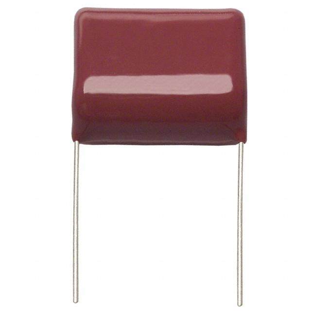
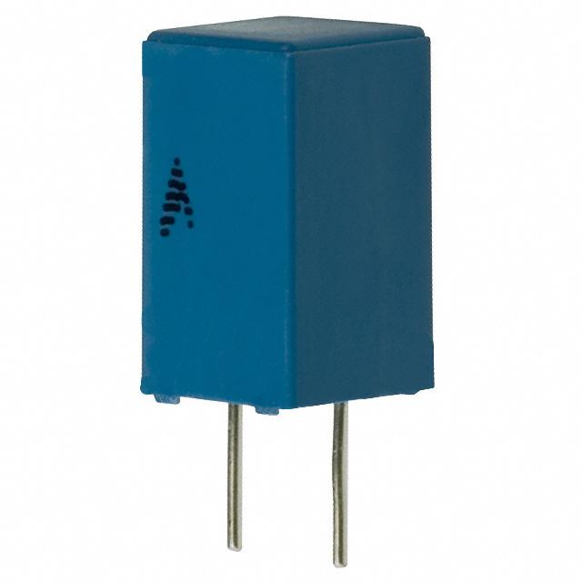
BFC237051222产品简介:
ICGOO电子元器件商城为您提供BFC237051222由Vishay设计生产,在icgoo商城现货销售,并且可以通过原厂、代理商等渠道进行代购。 BFC237051222价格参考¥0.38-¥0.38。VishayBFC237051222封装/规格:薄膜电容器, 2200pF 薄膜电容器 220V 400V 聚酯,金属化 径向。您可以下载BFC237051222参考资料、Datasheet数据手册功能说明书,资料中有BFC237051222 详细功能的应用电路图电压和使用方法及教程。
Vishay BC Components 是知名的电子元器件制造商,其 BFC237051222 是一款薄膜电容器。该型号常用于需要高稳定性、低损耗和高可靠性的电路中,典型应用场景包括:

1. 电源滤波:用于开关电源、DC-DC转换器中,滤除高频噪声,提高电源质量。
2. 音频设备:在音响系统、放大器中作为耦合电容或滤波电容,因其低失真和高音质表现。
3. 工业控制:用于变频器、电机驱动器等工业设备中,保障电路稳定运行。
4. 测量仪器:如示波器、信号发生器等精密仪器中,用于信号处理和滤波。
5. 汽车电子:在车载电源系统或音频系统中,提供稳定的电容性能。

该电容具有良好的温度特性和长寿命,适合高要求的电子设备使用。
| 参数 | 数值 |
| 产品目录 | |
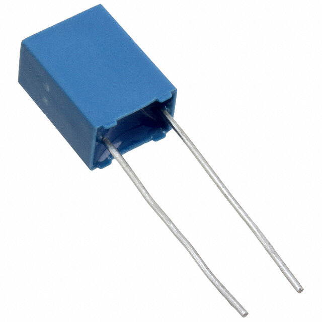
| 描述 | CAP FILM 2200PF 400VDC RADIAL薄膜电容器 .0022uF 10% 400volts |
| ESR(等效串联电阻) | - |
| 产品分类 | |
| 品牌 | Vishay |
| 产品手册 | |
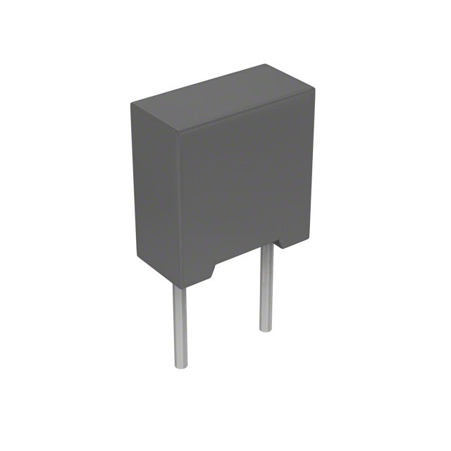
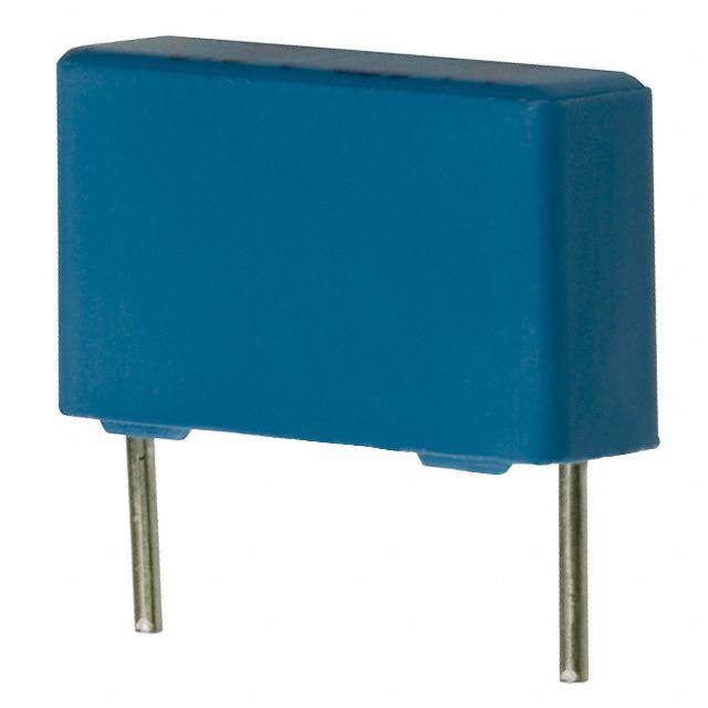
| 产品图片 |
|
| rohs | 符合RoHS无铅 / 符合限制有害物质指令(RoHS)规范要求 |
| 产品系列 | 薄膜电容器,Vishay BFC237051222MKT370 |
| 数据手册 | |
| 产品型号 | BFC237051222 |
| 产品 | General Film Capacitors |
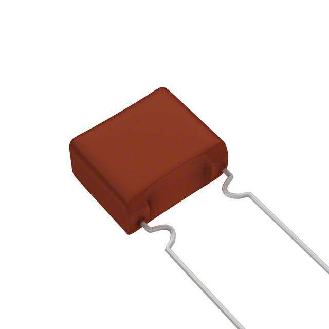
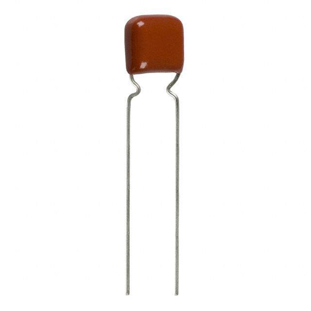
| 产品目录绘图 |
|
| 产品目录页面 | |
| 产品种类 | Radial Metallized Polyester Film Capacitor Potted |
| 介电材料 | 聚酯,金属化 |
| 其它名称 | 2222 370 51222 |
| 包装 | 散装 |
| 商标 | Vishay |
| 外壳宽度 | 2.5 mm |
| 外壳长度 | 7.2 mm |
| 外壳高度 | 6.5 mm |
| 大小/尺寸 | 0.283" 长 x 0.098" 宽(7.20mm x 2.50mm) |
| 安装类型 | 通孔 |
| 容差 | 10 % |
| 封装/外壳 | 径向 |
| 工作温度 | -55°C ~ 105°C |
| 工厂包装数量 | 2000 |
| 应用 | 通用 |
| 引线直径 | 0.5 mm |
| 引线间距 | 0.200"(5.08mm) |
| 引线间隔 | 5.08 mm |
| 损耗因数DF | 75 |
| 标准包装 | 2,000 |
| 特性 | - |
| 电介质 | Polyester |
| 电压额定值AC | 250 V |
| 电压额定值DC | 400 V |
| 电容 | 2200 pF |
| 端接 | PC 引脚 |
| 端接类型 | Radial |
| 类型 | Metallized Polyester Film Capacitor |
| 系列 | MKT370 |
| 零件号别名 | 222237051222 |
| 额定电压-AC | 220V |
| 额定电压-DC | 400V |
| 高度-安装(最大值) | 0.256"(6.50mm) |


- 商务部:美国ITC正式对集成电路等产品启动337调查
- 曝三星4nm工艺存在良率问题 高通将骁龙8 Gen1或转产台积电
- 太阳诱电将投资9.5亿元在常州建新厂生产MLCC 预计2023年完工
- 英特尔发布欧洲新工厂建设计划 深化IDM 2.0 战略
- 台积电先进制程称霸业界 有大客户加持明年业绩稳了
- 达到5530亿美元!SIA预计今年全球半导体销售额将创下新高
- 英特尔拟将自动驾驶子公司Mobileye上市 估值或超500亿美元
- 三星加码芯片和SET,合并消费电子和移动部门,撤换高东真等 CEO
- 三星电子宣布重大人事变动 还合并消费电子和移动部门
- 海关总署:前11个月进口集成电路产品价值2.52万亿元 增长14.8%
PDF Datasheet 数据手册内容提取
MKT370 www.vishay.com Vishay BCcomponents DC Film Capacitors MKT Radial Potted Type FEATURES • 5.08 mm lead pitch • Supplied loose in box, taped on ammopack or reel • AEC-Q200 qualified (rev. D) • Material categorization: for definitions of compliance please see www.vishay.com/doc?99912 APPLICATIONS Blocking and coupling, bypass and energy reservoir, telecom, industrial, consumer. QUICK REFERENCE DATA Capacitance range (E12 series) 0.00068 μF to 1.5 μF Capacitance tolerance ± 10 %, ± 5 % Rated DC voltage 50 V, 63 V, 250 V, 400 V, 630 V Rated AC voltage 32 V, 40 V, 63 V, 160 V, 220 V 55/100/56 for rated voltage 50 V and 63 V Climatic testing class acc. to IEC 60068-1 55/105/56 for rated voltage > 63 V 100 °C for rated voltage 50 V and 63 V Maximum application temperature 105 °C for rated voltage > 63 V Rated temperature 85 °C Reference standards IEC 60384-2 Dielectric Polyester film Electrodes Metallized Mono construction Construction Triple construction for 630 V, 0.00068 μF to 0.0018 μF Encapsulation Flame retardant plastic case and epoxy resin (UL-class 94 V-0) Leads Tinned wire C-value; tolerance; rated voltage; manufacturer’s symbol; Marking year and week of manufacture; manufacturer’s type Performance grade Grade 1 (long life) Note • For more detailed data and test requirements, contact dc-film@vishay.com DIMENSIONS in millimeters l w h l t P ± 0.3 Ø d t Revision: 08-Aug-2018 1 Document Number: 28108 For technical questions, contact: dc-film@vishay.com THIS DOCUMENT IS SUBJECT TO CHANGE WITHOUT NOTICE. THE PRODUCTS DESCRIBED HEREIN AND THIS DOCUMENT ARE SUBJECT TO SPECIFIC DISCLAIMERS, SET FORTH AT www.vishay.com/doc?91000
MKT370 www.vishay.com Vishay BCcomponents COMPOSITION OF CATALOG NUMBER TYPE AND PITCHES CAPACITANCE MULTIPLIER (numerically) 370 5.08mm (nF) 0.1 2 Example: 104 =10x10 =100nF 1 3 10 4 100 5 BFC2 370 XX YY Y 2222 (*) 370 XX YY Y (*) Old ordering number PREFERRED TYPES TYPE PACKAGING LEAD CONFIGURATION C-TOL. 63V 100V 250V 400V Lead length ± 10 % 11 21 41 51 4.0 mm + 1.0 mm/- 0.5 mm ± 5 % 12 22 42 52 Loose in box ± 10 % 15 25 45 55 Lead length 26.0 mm ± 2.0 mm 370 ± 5 % 16 26 46 56 (standard size) H=18.5mm; P =12.7mm; ± 10 % 18 28 48 58 Taped on reel (1) 0 Reel diameter = 356 mm ± 5 % 19 29 49 59 ± 10 % 75 85 35 65 Ammopack (2) H=18.5mm; P =12.7mm 0 ± 5 % 76 86 36 66 PREFERRED TYPES TYPE PACKAGING LEAD CONFIGURATION C-TOL. 100V 250V 400V 630V Lead length ± 10 % CE EE FE GE 4.0 mm + 1.0 mm/- 0.5 mm ± 5 % CF EF FF GF Loose in box ± 10 % CH EH FH GH Lead length 26.0 mm ± 2.0 mm 370 ± 5 % CI EI FI GI (compact size) H=18.5mm; P =12.7mm; ± 10 % CL EL FL GL Taped on reel (1) 0 Reel diameter = 356 mm ± 5 % CM EM FM GM ± 10 % CB EB FB GB Ammopack (2) H=18.5mm; P =12.7mm 0 ± 5 % CC EC FC GC Notes • For detailed tape specifications refer to packaging information: www.vishay.com/doc?28139 or end of catalog (1) Reel diameter = 356 mm is available on request (2) H = in-tape height; P = sprocket hole distance; for detailed specifications refer to packaging information 0 Revision: 08-Aug-2018 2 Document Number: 28108 For technical questions, contact: dc-film@vishay.com THIS DOCUMENT IS SUBJECT TO CHANGE WITHOUT NOTICE. THE PRODUCTS DESCRIBED HEREIN AND THIS DOCUMENT ARE SUBJECT TO SPECIFIC DISCLAIMERS, SET FORTH AT www.vishay.com/doc?91000
MKT370 www.vishay.com Vishay BCcomponents SPECIFIC REFERENCE DATA (Standard Size) DESCRIPTION VALUE Tangent of loss angle: at 1 kHz at 10 kHz at 100 kHz C 0.1 μF 75 x 10-4 130 x 10-4 220 x 10-4 0.1 μF < C 0.47 μF 75 x 10-4 130 x 10-4 300 x 10-4 0.47 μF < C 1.5 μF 75 x 10-4 130 x 10-4 - 50 V /63 V 100 V 250 V 400 V DC DC DC DC DC Rated voltage pulse slope (dU/dt) at R 60 V/μs 110 V/μs 330 V/μs 630 V/μs R between leads, for C 0.33 μF at 10 V; 1 min > 15 000 M at 100 V; 1 min > 15 000 M > 30 000 M > 30 000 M RC between leads 0.33 μF < C 1.0 μF at 10 V; 1 min > 5000 s C > 1.0 μF at 10 V; 1 min > 1000 s C > 0.33 μF at 100 V; 1 min > 5000 s R between interconnecting leads and case (foil method) > 30 000 M > 30 000 M > 30 000 M > 30 000 M Withstanding (DC) voltage (cut off current 10 mA) (1); rise time 1000 V/s 100 V; 1 min 160 V; 1 min 400 V; 1 min 640 V; 1 min rise time 100 V/s Withstanding (DC) voltage between leads and case 200 V; 1 min 200 V; 1 min 500 V; 1 min 800 V; 1 min Maximum application temperature 100 °C 105 °C Note (1) See “Voltage Proof Test for Metallized Film Capacitors”: www.vishay.com/doc?28169 SPECIFIC REFERENCE DATA (Compact Size) DESCRIPTION VALUE Tangent of loss angle: at 1 kHz at 10 kHz at 100 kHz C 0.1 μF 75 x 10-4 130 x 10-4 220 x 10-4 0.1 μF < C 0.47 μF 75 x 10-4 130 x 10-4 300 x 10-4 C > 0.47 μF 75 x 10-4 130 x 10-4 - 100 V 250 V 400 V 630 V DC DC DC DC Rated voltage pulse slope (dU/dt) at R 37 V/μs 44 V/μs 200 V/μs 540 V/μs R between leads, for C 0.33 μF at 100 V; 1 min > 15 000 M > 30 000 M > 30 000 M > 30 000 M RC between leads C > 0.33 μF at 100 V; 1 min > 5000 s R between interconnecting leads and case (foil method) > 30 000 M > 30 000 M > 30 000 M > 30 000 M Withstanding (DC) voltage (cut off current 10 mA) (1); rise time 1000 V/s 160 V; 1 min 400 V; 1 min 640 V; 1 min 1008 V; 1 min rise time 100 V/s Withstanding (DC) voltage between leads and case 200 V; 1 min 500 V; 1 min 800 V; 1 min 1260 V; 1 min Maximum application temperature 100 °C 105 °C Note (1) See “Voltage Proof Test for Metallized Film Capacitors”: www.vishay.com/doc?28169 Revision: 08-Aug-2018 3 Document Number: 28108 For technical questions, contact: dc-film@vishay.com THIS DOCUMENT IS SUBJECT TO CHANGE WITHOUT NOTICE. THE PRODUCTS DESCRIBED HEREIN AND THIS DOCUMENT ARE SUBJECT TO SPECIFIC DISCLAIMERS, SET FORTH AT www.vishay.com/doc?91000
MKT370 www.vishay.com Vishay BCcomponents ELECTRICAL DATA AND ORDERING INFORMATION (Standard Size) CATALOG NUMBER BFC2 370 XXYYY AND PACKAGING AMMOPACK LOOSE IN BOX REEL H = 18.5 mm; DIMENSIONS SHORT LEADS LONG LEADS U CAP. MASS P = 12.7 mm C-VALUE RDC w x h x l 0 (V) (μF) (g) (1) (mm) C-TOL. = C-TOL. = C-TOL. = C-TOL. = C-TOL. = C-TOL. = C-TOL. = C-TOL. = ± 10 % ± 5 % ± 10 % ± 5 % ± 10 % ± 5 % ± 10 % ± 5 % XX XX XX XX XX XX XX XX ..YYY (SPQ) (SPQ) (SPQ) (SPQ) (SPQ) (SPQ) (SPQ) (SPQ) U = 32 V; PITCH = 5.08 mm ± 0.30 mm; d = 0.50 mm ± 0.05 mm RAC t 50 1.2 75… 76… 11… 12… 15… 16… 18… 19… 125 6.0 x 11.0 x 7.2 0.64 1.5 (750) (750) (2000) (2000) (1000) (1000) (1000) (1000) 155 U = 40 V; PITCH = 5.08 mm ± 0.30 mm; d = 0.50 mm ± 0.05 mm RAC t 0.056 563 0.068 683 0.082 823 75… 76… 11… 12… 15… 16… 18… 19… 0.10 2.5 x 6.5 x 7.2 0.18 104 (2000) (2000) (2000) (2000) (1000) (1000) (2000) (2000) 0.12 124 0.15 154 0.18 184 63 0.22 224 0.27 274 75… 76… 11… 12… 15… 16… 18… 19… 0.33 3.5 x 8.0 x 7.2 0.3 334 (1500) (1500) (2000) (2000) (1000) (1000) (1500) (1500) 0.39 394 0.47 474 0.56 75… 76… 11… 12… 15… 16… 18… 19… 564 4.5 x 9.0 x 7.2 0.42 0.68 (1000) (1000) (2000) (2000) (1000) (1000) (1000) (1000) 684 0.82 75… 76… 11… 12… 15… 16… 18… 19… 824 6.0 x 11.0 x 7.2 0.64 1.0 (750) (750) (2000) (2000) (1000) (1000) (1000) (1000) 105 U = 63 V; PITCH = 5.08 mm ± 0.30 mm; d = 0.50 mm ± 0.05 mm RAC t 0.0010 102 0.0012 122 0.0015 152 0.0018 182 0.0022 222 0.0027 272 0.0033 332 0.0039 392 0.0047 472 0.0056 562 0.0068 682 0.0082 822 85... 86... 21... 22... 25... 26... 28... 29... 0.010 2.5 x 6.5 x 7.2 0.18 103 (2000) (2000) (2000) (2000) (1000) (1000) (2000) (2000) 0.012 123 0.015 153 0.018 183 100 0.022 223 0.027 273 0.033 333 0.039 393 0.047 473 0.056 563 0.068 683 0.082 823 0.10 104 0.12 124 85... 86... 21... 22... 25... 26... 28... 29... 0.15 3.5 x 8.0 x 7.2 0.30 154 (1500) (1500) (2000) (2000) (1000) (1000) (1500) (1500) 0.18 184 0.22 224 85... 86... 21... 22... 25... 26... 28... 29... 0.27 4.5 x 9.0 x 7.2 0.42 274 (1000) (1000) (2000) (2000) (1000) (1000) (1000) (1000) 0.33 334 0.39 85... 86... 21... 22... 25... 26... 28... 29... 394 6.0 x 11.0 x 7.2 0.64 0.47 (750) (750) (2000) (2000) (1000) (1000) (1000) (1000) 474 Revision: 08-Aug-2018 4 Document Number: 28108 For technical questions, contact: dc-film@vishay.com THIS DOCUMENT IS SUBJECT TO CHANGE WITHOUT NOTICE. THE PRODUCTS DESCRIBED HEREIN AND THIS DOCUMENT ARE SUBJECT TO SPECIFIC DISCLAIMERS, SET FORTH AT www.vishay.com/doc?91000
MKT370 www.vishay.com Vishay BCcomponents ELECTRICAL DATA AND ORDERING INFORMATION (Standard Size) CATALOG NUMBER BFC2 370 XXYYY AND PACKAGING AMMOPACK LOOSE IN BOX REEL H = 18.5 mm; DIMENSIONS SHORT LEADS LONG LEADS U CAP. MASS P = 12.7 mm C-VALUE RDC w x h x l 0 (V) (μF) (g) (1) (mm) C-TOL. = C-TOL. = C-TOL. = C-TOL. = C-TOL. = C-TOL. = C-TOL. = C-TOL. = ± 10 % ± 5 % ± 10 % ± 5 % ± 10 % ± 5 % ± 10 % ± 5 % XX XX XX XX XX XX XX XX ..YYY (SPQ) (SPQ) (SPQ) (SPQ) (SPQ) (SPQ) (SPQ) (SPQ) U = 160 V; PITCH = 5.08 mm ± 0.30 mm; d = 0.50 mm ± 0.05 mm RAC t 0.0010 102 0.0012 122 0.0015 152 0.0018 182 0.0022 222 0.0027 272 0.0033 332 0.0039 35... 36... 41... 42... 45... 46... 48... 49... 392 2.5 x 6.5 x 7.2 0.18 0.0047 (2000) (2000) (2000) (2000) (1000) (1000) (2000) (2000) 472 0.0056 562 0.0068 682 0.0082 822 250 0.010 103 0.012 123 0.015 153 0.018 183 0.022 223 35... 36... 41... 42... 45... 46... 48... 49... 0.027 3.5 x 8.0 x 7.2 0.30 273 (1500) (1500) (2000) (2000) (1000) (1000) (1500) (1500) 0.033 333 0.039 393 35... 36... 41... 42... 45... 46... 48... 49... 0.047 4.5 x 9.0 x 7.2 0.42 473 (1000) (1000) (2000) (2000) (1000) (1000) (1000) (1000) 0.056 563 0.068 683 35... 36... 41... 42... 45... 46... 48... 49... 0.082 6.0 x 11.0 x 7.2 0.64 823 (750) (750) (2000) (2000) (1000) (1000) (1000) (1000) 0.10 104 U = 220 V; PITCH = 5.08 mm ± 0.30 mm; d = 0.50 mm ± 0.05 mm RAC t 0.0010 102 0.0012 122 0.0015 152 0.0018 182 0.0022 222 0.0027 65... 66... 51... 52... 55... 56... 58... 59... 272 2.5 x 6.5 x 7.2 0.18 0.0033 (2000) (2000) (2000) (2000) (1000) (1000) (2000) (2000) 332 0.0039 392 0.0047 472 0.0056 562 400 0.0068 682 0.0082 822 0.010 103 65... 66... 51... 52... 55... 56... 58... 59... 0.012 3.5 x 8.0 x 7.2 0.30 123 (1500) (1500) (2000) (2000) (1000) (1000) (1500) (1500) 0.015 153 0.018 183 65... 66... 51... 52... 55... 56... 58... 59... 0.022 4.5 x 9.0 x 7.2 0.42 223 (1000) (1000) (2000) (2000) (1000) (1000) (1000) (1000) 0.027 273 0.033 333 65... 66... 51... 52... 55... 56... 58... 59... 0.039 6.0 x 11.0 x 7.2 0.64 393 (750) (750) (2000) (2000) (1000) (1000) (1000) (1000) 0.047 473 Notes • SPQ = Standard Packing Quantity (1) Weight for short lead product only Revision: 08-Aug-2018 5 Document Number: 28108 For technical questions, contact: dc-film@vishay.com THIS DOCUMENT IS SUBJECT TO CHANGE WITHOUT NOTICE. THE PRODUCTS DESCRIBED HEREIN AND THIS DOCUMENT ARE SUBJECT TO SPECIFIC DISCLAIMERS, SET FORTH AT www.vishay.com/doc?91000
MKT370 www.vishay.com Vishay BCcomponents ELECTRICAL DATA AND ORDERING INFORMATION (Compact Size) CATALOG NUMBER BFC2 370 XXYYY AND PACKAGING AMMOPACK LOOSE IN BOX REEL H = 18.5 mm; DIMENSIONS SHORT LEADS LONG LEADS U CAP. MASS P = 12.7 mm C-VALUE RDC w x h x l 0 (V) (μF) (g) (1) (mm) C-TOL. = C-TOL. = C-TOL. = C-TOL. = C-TOL. = C-TOL. = C-TOL. = C-TOL. = ± 10 % ± 5 % ± 10 % ± 5 % ± 10 % ± 5 % ± 10 % ± 5 % XX XX XX XX XX XX XX XX ..YYY (SPQ) (SPQ) (SPQ) (SPQ) (SPQ) (SPQ) (SPQ) (SPQ) U = 40 V; PITCH = 5.08 mm ± 0.30 mm; d = 0.50 mm ± 0.05 mm RAC t 0.12 124 0.15 154 0.18 CB... CC... CE... CF... CH... CI... CL... CM... 184 3.5 x 8.0 x 7.2 0.30 0.22 (1500) (1500) (2000) (2000) (1000) (1000) (1500) (1500) 224 100 0.27 274 0.33 334 0.39 CB... CC... CE... CF... CH... CI... CL... CM... 394 4.5 x 9.0 x 7.2 0.42 0.47 (1000) (1000) (2000) (2000) (1000) (1000) (1000) (1000) 474 CB... CC... CE... CF... CH... CI... CL... CM... 0.56 6.0 x 11.0 x 7.2 0.64 564 (750) (750) (2000) (2000) (1000) (1000) (1000) (1000) U = 63 V; PITCH = 5.08 mm ± 0.30 mm; d = 0.50 mm ± 0.05 mm RAC t 0.022 EB... EC... EE... EF... EH... EI... EL... EM... 223 2.5 x 6.5 x 7.2 0.18 0.027 (2000) (2000) (2000) (2000) (1000) (1000) (2000) (2000) 273 0.033 333 0.039 393 EB... EC... EE... EF... EH... EI... EL... EM... 0.047 3.5 x 8.0 x 7.2 0.30 473 (1500) (1500) (2000) (2000) (1000) (1000) (1500) (1500) 0.056 563 250 0.068 683 0.082 EB... EC... EE... EF... EH... EI... EL... EM... 823 4.5 x 9.0 x 7.2 0.42 0.10 (1000) (1000) (2000) (2000) (1000) (1000) (1000) (1000) 104 0.12 124 0.15 EB... EC... EE... EF... EH... EI... EL... EM... 154 6.0 x 11.0 x 7.2 0.64 0.18 (750) (750) (2000) (2000) (1000) (1000) (1000) (1000) 184 0.22 224 U = 160 V; PITCH = 5.08 mm ± 0.30 mm; d = 0.50 mm ± 0.05 mm RAC t 0.010 103 0.012 FB... FC... FE... FF... FH... FI... FL... FM... 123 2.5 x 6.5 x 7.2 0.18 0.015 (2000) (2000) (2000) (2000) (1000) (1000) (2000) (2000) 153 0.018 183 0.022 223 0.027 FB... FC... FE... FF... FH... FI... FL... FM... 273 400 3.5 x 8.0 x 7.2 0.30 0.033 (1500) (1500) (2000) (2000) (1000) (1000) (1500) (1500) 333 0.039 393 0.047 FB... FC... FE... FF... FH... FI... FL... FM... 473 4.5 x 9.0 x 7.2 0.42 0.056 (1000) (1000) (2000) (2000) (1000) (1000) (1000) (1000) 563 0.068 683 FB... FC... FE... FF... FH... FI... FL... FM... 0.082 6.0 x 11.0 x 7.2 0.64 823 (750) (750) (2000) (2000) (1000) (1000) (1000) (1000) 0.10 104 Revision: 08-Aug-2018 6 Document Number: 28108 For technical questions, contact: dc-film@vishay.com THIS DOCUMENT IS SUBJECT TO CHANGE WITHOUT NOTICE. THE PRODUCTS DESCRIBED HEREIN AND THIS DOCUMENT ARE SUBJECT TO SPECIFIC DISCLAIMERS, SET FORTH AT www.vishay.com/doc?91000
MKT370 www.vishay.com Vishay BCcomponents ELECTRICAL DATA AND ORDERING INFORMATION (Compact Size) CATALOG NUMBER BFC2 370 XXYYY AND PACKAGING AMMOPACK LOOSE IN BOX REEL H = 18.5 mm; DIMENSIONS SHORT LEADS LONG LEADS U CAP. MASS P = 12.7 mm C-VALUE RDC w x h x l 0 (V) (μF) (g) (1) (mm) C-TOL. = C-TOL. = C-TOL. = C-TOL. = C-TOL. = C-TOL. = C-TOL. = C-TOL. = ± 10 % ± 5 % ± 10 % ± 5 % ± 10 % ± 5 % ± 10 % ± 5 % XX XX XX XX XX XX XX XX ..YYY (SPQ) (SPQ) (SPQ) (SPQ) (SPQ) (SPQ) (SPQ) (SPQ) U = 220 V; PITCH = 5.08 mm ± 0.30 mm; d = 0.50 mm ± 0.05 mm RAC t 0.0010 102 0.0012 122 0.0015 152 0.0018 182 0.0020 202 0.0022 222 0.0024 242 GB... GC... GE... GF... GH... GI... GL... GM... 0.0027 3.5 x 8.0 x 7.2 0.35 272 (1500) (1500) (2000) (2000) (1000) (1000) (1500) (1500) 0.0033 332 0.0039 392 630 0.0047 472 0.0056 562 0.0068 682 0.0082 822 0.010 103 0.012 GB... GC... GE... GF... GH... GI... GL... GM... 123 4.5 x 9.0 x 7.2 0.45 0.015 (1000) (1000) (2000) (2000) (1000) (1000) (1000) (1000) 153 0.018 183 0.022 GB... GC... GE... GF... GH... GI... GL... GM... 223 6.0 x 11.0 x 7.2 0.65 0.027 (750) (750) (2000) (2000) (1000) (1000) (1000) (1000) 273 0.033 333 Notes • SPQ = Standard Packing Quantity (1) Weight for short lead product only Revision: 08-Aug-2018 7 Document Number: 28108 For technical questions, contact: dc-film@vishay.com THIS DOCUMENT IS SUBJECT TO CHANGE WITHOUT NOTICE. THE PRODUCTS DESCRIBED HEREIN AND THIS DOCUMENT ARE SUBJECT TO SPECIFIC DISCLAIMERS, SET FORTH AT www.vishay.com/doc?91000
MKT370 www.vishay.com Vishay BCcomponents MOUNTING Normal Use The capacitors are designed for mounting on printed-circuit boards. The capacitors packed in bandoliers are designed for mounting in printed-circuit boards by means of automatic insertion machines. For detailed tape specifications refer to packaging information: www.vishay.com/doc?28139 or end of catalog. Specific Method of Mounting to Withstand Vibration and Shock In order to withstand vibration and shock tests, it must be ensured that stand-off pips are in good contact with the printed-circuit board: • For pitches 15 mm capacitors shall be mechanically fixed by the leads • For larger pitches the capacitors shall be mounted in the same way and the body clamped Space Requirements on Printed Circuit Board The maximum space for length (l ), width (w ) and height (h ) of film capacitors to take in account on the printed circuit max. max. max. board is shown in the drawings. • For products with pitch 15 mm, w = l = 0.3 mm; h = 0.1 mm Eccentricity defined as in drawing. The maximum eccentricity is smaller than or equal to the lead diameter of the product concerned. w = W + Δ max. Eccentricity I = I + Δ CBA116 max. h = h + Δ max. Seating plane SOLDERING CONDITIONS For general soldering conditions and wave soldering profile, we refer to the application note: “Soldering Guidelines for Film Capacitors”: www.vishay.com/doc?28171 Storage Temperature T = -25 °C to +35 °C with with relative humidity of maximum 75 % without condensation stg Ratings and Characteristics Reference Conditions Unless otherwise specified, all electrical values apply to an ambient temperature of 23 °C ± 1 °C, an atmospheric pressure of 86 kPa to 106 kPa and a relative humidity of 50 % ± 2 %. For reference testing, a conditioning period shall be applied over 96 h ± 4 h by heating the products in a circulating air oven at the rated temperature and a relative humidity not exceeding 20 %. Revision: 08-Aug-2018 8 Document Number: 28108 For technical questions, contact: dc-film@vishay.com THIS DOCUMENT IS SUBJECT TO CHANGE WITHOUT NOTICE. THE PRODUCTS DESCRIBED HEREIN AND THIS DOCUMENT ARE SUBJECT TO SPECIFIC DISCLAIMERS, SET FORTH AT www.vishay.com/doc?91000
MKT370 www.vishay.com Vishay BCcomponents CHARACTERISTICS 6 6 C/C%) 1 kHz C/C%) 1 kHz Δ(4 a. 63 V series Δ(4 ab.. 16030 V V s eserireiess c. 250 V series d. 400 V series d 2 2 max. max. c 0 0 typical typical b -2 -2 a a -4 -4 min. min. -6 -6 -60 -20 20 60 Tamb (°C) 100 -60 -20 20 60 Tamb (°C) 100 Capacitance as a function of ambient temperature Capacitance as a function of ambient temperature (typical curve) for voltage 63 V (typical curve) for voltages > 63 V 2 e102 c n ΔC/C (%)1 ImpedaΩ1 ()01 63 V; 1 µF 63 V; 100 nF 250 V; 10 nF 0 100 -1 10-1 -2 10-2 -3 10-3 102 103 104 f (Hz) 105 104 105 106 107 f (Hz) 108 Capacitance as a function of frequency Impedance as a function of frequency (typical curve) 102 102 Standard size Standard size e e g g a a oltV) oltV) V( V( C C A A 110001 Tamb ≤ 85 °C, 63 VDC 102150206000 n nnnFFFF 110001 85 °C < Tamb ≤ 100 °C, 63 VDC 12102000500 n6 nnF nFFF 101 102 103 104 f (Hz) 105 101 102 103 104 f (Hz) 105 Max. AC voltage as a function of frequency Max. AC voltage as a function of frequency Revision: 08-Aug-2018 9 Document Number: 28108 For technical questions, contact: dc-film@vishay.com THIS DOCUMENT IS SUBJECT TO CHANGE WITHOUT NOTICE. THE PRODUCTS DESCRIBED HEREIN AND THIS DOCUMENT ARE SUBJECT TO SPECIFIC DISCLAIMERS, SET FORTH AT www.vishay.com/doc?91000
MKT370 www.vishay.com Vishay BCcomponents CHARACTERISTICS 102 102 Standard size Standard size e e g g a a oltV) oltV) V( V( AC 2122 nnFF AC 101 Tamb ≤ 85 °C, 100 VDC 31430700 n nnFFF 101 85 °C < Tamb ≤ 105 °C, 100 VDC 314123072200 nnn nnFFFFF 100 100 101 102 103 104 f (Hz) 105 101 102 103 104 f (Hz) 105 Max. AC voltage as a function of frequency Max. AC voltage as a function of frequency 102 102 Compact size Compact size e e g g a a oltV) oltV) V( V( C C A A 101 212000 n nFF 101 212000 n nFF T ≤ 85 °C, 100 V 85 °C < T ≤ 105 °C, 100 V amb DC amb DC 100 100 101 102 103 104 f (Hz) 105 101 102 103 104 f (Hz) 105 Max. AC voltage as a function of frequency Max. AC voltage as a function of frequency 103 103 e e ag Standard size ag Standard size oltV) oltV) V( V( C C A A 102 102 101 1404.102770 2 nnn nFnFFFF 101 101404207 n.2 7nnF n FFnFF T ≤ 85 °C, 250 V 85 °C < T ≤ 105 °C, 250 V amb DC amb DC 100 100 101 102 103 104 f (Hz) 105 101 102 103 104 f (Hz) 105 Max. AC voltage as a function of frequency Max. AC voltage as a function of frequency Revision: 08-Aug-2018 10 Document Number: 28108 For technical questions, contact: dc-film@vishay.com THIS DOCUMENT IS SUBJECT TO CHANGE WITHOUT NOTICE. THE PRODUCTS DESCRIBED HEREIN AND THIS DOCUMENT ARE SUBJECT TO SPECIFIC DISCLAIMERS, SET FORTH AT www.vishay.com/doc?91000
MKT370 www.vishay.com Vishay BCcomponents CHARACTERISTICS 102 102 Compact size Compact size e e g g a a C Volt(V) 22 nF C Volt(V) A 47 nF A 101 100 nF 101 22 nF 47 nF 100 nF T ≤ 85 °C, 250 V 85 °C < T ≤ 105 °C, 250 V amb DC amb DC 100 100 101 102 103 104 f (Hz) 105 101 102 103 104 f (Hz) 105 Max. AC voltage as a function of frequency Max. AC voltage as a function of frequency 103 103 e e g g a Standard size a Standard size oltV) oltV) V( V( C C A A 110021 3130 4n .2nF7.1F2 n. 0nF FnF 110021 3130 4n .2nF7.1F2 n. 0nF FnF T ≤ 85 °C, 400 V 85 °C < T ≤ 105 °C, 400 V amb DC amb DC 100 100 101 102 103 104 f (Hz) 105 101 102 103 104 f (Hz) 105 Max. AC voltage as a function of frequency Max. AC voltage as a function of frequency 103 103 ge Compact size ge Compact size a a oltV) oltV) V( V( C C A A 102 102 101 1040127 n02 nF nnFFF 101 1040.27 .1n2 n.F 0nF FnF T ≤ 85 °C, 400 V 85 °C < T ≤ 105 °C, 400 V amb DC amb DC 100 100 101 102 103 104 f (Hz) 105 101 102 103 104 f (Hz) 105 Max. AC voltage as a function of frequency Max. AC voltage as a function of frequency Revision: 08-Aug-2018 11 Document Number: 28108 For technical questions, contact: dc-film@vishay.com THIS DOCUMENT IS SUBJECT TO CHANGE WITHOUT NOTICE. THE PRODUCTS DESCRIBED HEREIN AND THIS DOCUMENT ARE SUBJECT TO SPECIFIC DISCLAIMERS, SET FORTH AT www.vishay.com/doc?91000
MKT370 www.vishay.com Vishay BCcomponents CHARACTERISTICS 102 102 e Compact size e Compact size g g a a oltV) oltV) V( V( C C A A 101 101 0. 6 2.2 nF 8 nF 2.2 n0F.68 nF Tamb ≤ 85 °C, 630 VDC 33 nF 85 °C < Tamb ≤ 105 °C, 630 VDC 33 nF 100 100 101 102 103 104 f (Hz) 105 101 102 103 104 f (Hz) 105 Max. AC voltage as a function of frequency Max. AC voltage as a function of frequency Maximum RMS current (sinewave) as a function of frequency The maximum RMS current is defined by I = x C x U . AC AC U is the maximum AC voltage depending on the ambient temperature in the curves “Max. RMS voltage and AC current as a AC function of frequency”. 103 105 or ct pation fa-4)(x 10 54 RC (s) Dissi 321 104 102 Curve 1: C = 0.33 µF 103 Curve 2: 0.33 µF, C = 1.2 µF Curve 3: 1.2 µF, C = 3.9 µF Curve 4: 3.9 µF, C = 6.8 µF Curve 5: C = 6.8 µF 101 102 102 103 104 f (Hz) 105 -50 0 50 T (°C) 100 amb Tangent of loss angle as a function of frequency Insulation resistance as a function of the ambient temperature (typical curve) (typical curve) 1.2 1.2 Factor1.0 factor1.0 0.8 0.8 0.6 0.6 0.4 0.4 0.2 0.2 0.0 0.0 -60 -20 20 60 T ( ° C ) 100 -60 -20 20 60 T ( ° C ) 100 amb amb Max. DC and AC voltage as a function of frequency Max. DC and AC voltage as a function of frequency for voltage 63 V for voltages > 63 V Revision: 08-Aug-2018 12 Document Number: 28108 For technical questions, contact: dc-film@vishay.com THIS DOCUMENT IS SUBJECT TO CHANGE WITHOUT NOTICE. THE PRODUCTS DESCRIBED HEREIN AND THIS DOCUMENT ARE SUBJECT TO SPECIFIC DISCLAIMERS, SET FORTH AT www.vishay.com/doc?91000
MKT370 www.vishay.com Vishay BCcomponents CHARACTERISTICS 16 16 C) C) T (° T (° Δ Δ 12 12 8 8 4 4 0 0 -60 -20 20 60 T ( ° C ) 100 -60 -20 20 60 T ( ° C ) 100 amb amb Maximum allowed component temperature rise (T) Maximum allowed component temperature rise (T) as a function of the ambient temperature (T ) for voltage 63 V as a function of the ambient temperature (T ) for voltages > 63 V amb amb HEAT CONDUCTIVITY (G) AS A FUNCTION OF (ORIGINAL) PITCH AND CAPACITOR BODY THICKNESS IN mW/°C W HEAT CONDUCTIVITY (mW/°C) max. (mm) PITCH 5 mm 2.5 2.5 3.5 3.0 4.5 4.0 6.0 5.5 POWER DISSIPATION AND MAXIMUM COMPONENT TEMPERATURE RISE The power dissipation must be limited in order not to exceed the maximum allowed component temperature rise as a function of the free ambient temperature. The power dissipation can be calculated according type detail specification “HQN-384-01/101: Technical Information Film Capacitors”, www.vishay.com/doc?28147. The component temperature rise (T) can be measured (see section “Measuring the component temperature” for more details) or calculated by T = P/G: • T = component temperature rise (°C) • P = power dissipation of the component (mW) • G = heat conductivity of the component (mW/°C) MEASURING THE COMPONENT TEMPERATURE A thermocouple must be attached to the capacitor body as in: Thermocouple The temperature is measured in unloaded (T ) and maximum loaded condition (T ). amb C The temperature rise is given by T = T - T . C amb To avoid radiation or convection, the capacitor should be tested in a wind-free box. Revision: 08-Aug-2018 13 Document Number: 28108 For technical questions, contact: dc-film@vishay.com THIS DOCUMENT IS SUBJECT TO CHANGE WITHOUT NOTICE. THE PRODUCTS DESCRIBED HEREIN AND THIS DOCUMENT ARE SUBJECT TO SPECIFIC DISCLAIMERS, SET FORTH AT www.vishay.com/doc?91000
MKT370 www.vishay.com Vishay BCcomponents APPLICATION NOTE AND LIMITING CONDITIONS These capacitors are not suitable for mains applications as across-the-line capacitors without additional protection, as described hereunder. These mains applications are strictly regulated in safety standards and therefore electromagnetic interference suppression capacitors conforming the standards must be used. For capacitors connected in parallel, normally the proof voltage and possibly the rated voltage must be reduced. For information depending of the capacitance value and the number of parallel connections contact: dc-film@vishay.com To select the capacitor for a certain application, the following conditions must be checked: 1.The peak voltage (U ) shall not be greater than the rated DC voltage (U ) P RDC 2.The peak-to-peak voltage (U ) shall not be greater than 22 x U to avoid the ionization inception level P-P RAC 3.The voltage peak slope (dU/dt) shall not exceed the rated voltage pulse slope in an RC-circuit at rated voltage and without ringing. If the pulse voltage is lower than the rated DC voltage, the rated voltage pulse slope may be multiplied by U and RDC divided by the applied voltage. For all other pulses following equation must be fulfilled: T 2 x d----U---2 x dtU x d----U--- dt RDC dtrated 0 T is the pulse duration. 4.The maximum component surface temperature rise must be lower than the limits (see figure max. allowed component temperature rise). 5.Since in circuits used at voltages over 280 V peak-to-peak the risk for an intrinsically active flammability after a capacitor breakdown (short circuit) increases, it is recommended that the power to the component is limited to 100 times the values mentioned in the table: “Heat conductivity” 6.When using these capacitors as across-the-line capacitor in the input filter for mains applications or as series connected with an impedance to the mains the applicant must guarantee that the following conditions are fulfilled in any case (spikes and surge voltages from the mains included). VOLTAGE CONDITIONS FOR 6 ABOVE 85 °C < Tamb 100 °C FOR 63 V ALLOWED VOLTAGES Tamb 85 °C 85 °C < Tamb 105 °C FOR > 63 V See “Max. AC voltage as function Maximum continuous RMS voltage U RAC of temperature CBB952” per characteristics Maximum temperature RMS-overvoltage (< 24 h) 1.25 x U U RAC RAC Maximum peak voltage (V ) (< 2 s) 1.6 x U 1.3 x U O-P RDC RDC EXAMPLE C = 330 nF - 63 V used for the voltage signal shown in next drawing. U = 40 V; U = 35 V; T = 100 μs; T = 200 μs P-P P 1 2 The ambient temperature is 35 °C Checking conditions: 1.The peak voltage U = 35 V is lower than 63 V P DC 2.The peak-to-peak voltage 40 V is lower than 22 x 40 V = 113 U AC P-P 3.The voltage pulse slope (dU/dt) = 40 V/100 μs = 0.4 V/μs This is lower than 60 V/μs (see specific reference data for each version) 4.The dissipated power is 16.2 mW as calculated with fourier terms The temperature rise for W = 3.5 mm and pitch = 5 mm will be 16.2 mW/3.0 mW/°C = 5.4 °C max. This is lower than 15 °C temperature rise at 35 °C, according figure max. allowed component temperature rise 5.Not applicable 6.Not applicable Voltage Signal Voltage U P U P-P Time T 1 T 2 Revision: 08-Aug-2018 14 Document Number: 28108 For technical questions, contact: dc-film@vishay.com THIS DOCUMENT IS SUBJECT TO CHANGE WITHOUT NOTICE. THE PRODUCTS DESCRIBED HEREIN AND THIS DOCUMENT ARE SUBJECT TO SPECIFIC DISCLAIMERS, SET FORTH AT www.vishay.com/doc?91000
MKT370 www.vishay.com Vishay BCcomponents INSPECTION REQUIREMENTS General Notes Sub-clause numbers of tests and performance requirements refer to the “Sectional Specification, Publication IEC 60384-2 and Specific Reference Data”. GROUP C INSPECTION REQUIREMENTS SUB-CLAUSE NUMBER AND TEST CONDITIONS PERFORMANCE REQUIREMENTS SUB-GROUP C1A PART OF SAMPLE OF SUB-GROUP C1 4.1 Dimensions (detail) As specified in chapters “MKT 370 General Data” of this specification 4.3.1Initial measurements Capacitance Tangent of loss angle: for C 470 nF at 100 kHz or for C > 470 nF at 10 kHz 4.3 Robustness of terminations Tensile and bending No visible damage 4.4 Resistance to soldering heat Method: 1A Solder bath: 280 °C ± 5 °C Duration: 10 s 4.14 Component solvent resistance Isopropylalcohol at room temperature Method: 2 Immersion time: 5 min ± 0.5 min Recovery time: min. 1 h, max. 2 h 4.4.2Final measurements Visual examination No visible damage Legible marking Capacitance |C/C| 2 % of the value measured initially Tangent of loss angle Increase of tan 0.005 for: C 100 nF or 0.010 for: 100 nF < C 220 nF or 0.015 for: 220 nF < C 470 nF and 0.003 for: C > 470 nF Compared to values measured in 4.3.1 SUB-GROUP C1B OTHER PART OF SAMPLE OF SUB-GROUP C1 4.6.1Initial measurements Capacitance Tangent of loss angle: for C 470 nF at 100 kHz or for C > 470 nF at 10 kHz 4.6 Rapid change of temperature A = -55 °C B =+100 °C for rated voltage 63 V +105 °C for rated voltage > 63 V 5 cycles Duration t = 30 min 4.7 Vibration Visual examination No visible damage Mounting: see section “Mounting” of this specification Procedure B4 Frequency range: 10 Hz to 55 Hz Amplitude: 0.75 mm or Acceleration 98 m/s2 (whichever is less severe) Total duration 6 h 4.7.2Final inspection Visual examination No visible damage Revision: 08-Aug-2018 15 Document Number: 28108 For technical questions, contact: dc-film@vishay.com THIS DOCUMENT IS SUBJECT TO CHANGE WITHOUT NOTICE. THE PRODUCTS DESCRIBED HEREIN AND THIS DOCUMENT ARE SUBJECT TO SPECIFIC DISCLAIMERS, SET FORTH AT www.vishay.com/doc?91000
MKT370 www.vishay.com Vishay BCcomponents GROUP C INSPECTION REQUIREMENTS SUB-CLAUSE NUMBER AND TEST CONDITIONS PERFORMANCE REQUIREMENTS SUB-GROUP C1B OTHER PART OF SAMPLE OF SUB-GROUP C1 4.9 Shock Mounting: see section “Mounting” of this specification Pulse shape: half sine Acceleration: 490 m/s2 Duration of pulse: 11 ms 4.9.3 Final measurements Visual examination No visible damage Capacitance |C/C| 3 % of the value measured in 4.6.1 Tangent of loss angle Increase of tan 0.010 for: C 220 nF or 0.015 for: 220 nF < C 470 nF and 0.003 for: C > 470 nF Compared to values measured in 4.6.1 Insulation resistance As specified in section “Specific Reference Data 370” of this specification SUB-GROUP C1 COMBINED SAMPLE OF SPECIMENS OF SUB-GROUPS C1A AND C1B 4.10 Climatic sequence 4.10.2 Dry heat Temperature: +100 °C for rated voltage 63 V +105 °C for rated voltage > 63 V Duration: 16 h 4.10.3 Damp heat cyclic Test Db, first cycle 4.10.4 Cold Temperature: -55 °C Duration: 2 h 4.10.6 Damp heat cyclic Voltage proof = U for 1 min within 15 min after No breakdown of flash-over RDC Test Db, remaining cycles removal from testchamber 4.10.6.2Final measurements Visual examination No visible damage Legible marking Capacitance |C/C| 5 % of the value measured in 4.4.2 or 4.9.3 Tangent of loss angle Increase of tan 0.010 for: C 220 nF or 0.015 for: 220 nF < C 470 nF and 0.005 for: C > 470 nF Compared to values measured in 4.3.1 or 4.6.1 Insulation resistance 50 % of values specified in section “Specific Reference Data 370” of this specification SUB-GROUP C2 4.11 Damp heat steady state 56 days, 40 °C, 90 % to 95 % RH 4.11.1 Initial measurements Capacitance Tangent of loss angle at 1 kHz Revision: 08-Aug-2018 16 Document Number: 28108 For technical questions, contact: dc-film@vishay.com THIS DOCUMENT IS SUBJECT TO CHANGE WITHOUT NOTICE. THE PRODUCTS DESCRIBED HEREIN AND THIS DOCUMENT ARE SUBJECT TO SPECIFIC DISCLAIMERS, SET FORTH AT www.vishay.com/doc?91000
MKT370 www.vishay.com Vishay BCcomponents GROUP C INSPECTION REQUIREMENTS SUB-CLAUSE NUMBER AND TEST CONDITIONS PERFORMANCE REQUIREMENTS SUB-GROUP C2 4.11.3Final measurements Voltage proof = U for 1 min within 15 min after No breakdown of flash-over RDC removal from testchamber Visual examination No visible damage Legible marking Capacitance |C/C| 5 % of the value measured in 4.11.1. Tangent of loss angle Increase of tan 0.005 Compared to values measured in 4.11.1 Insulation resistance 50 % of values specified in section “Specific Reference Data 370” of this specification SUB-GROUP C3 4.12 Endurance Duration: 2000 h 1.25 x URDC at 85 °C 0.8 x 1.25 URDC at +100 °C for rated voltage 63 V 0.8 x 1.25 URDC at +105 °C for rated voltage > 63 V 4.12.1Initial measurements Capacitance Tangent of loss angle: For C 470 nF at 100 kHz or for C > 470 nF at 10 kHz 4.12.5Final measurements Visual examination No visible damage Legible marking Capacitance |C/C| 5 % compared to values measured in 4.12.1 Tangent of loss angle Increase of tan 0.005 for at 85 °C 0.010 for at 100 °C for: C 220 nF or 0.015 for: 220 nF < C 470 nF and 0.003 for: C > 470 nF Compared to values measured in 4.12.1 Insulation resistance 50 % of values specified in section “Specific Reference Data 370” of this specification SUB-GROUP C4 4.13 Charge and discharge 10 000 cycles Charged to URDC Discharge resistance: U R = ------------------------------R-------------------------- C x 2.5 x dU/dtR 4.13.1Initial measurements Capacitance Tangent of loss angle: For C 470 nF at 100 kHz or for C > 470 nF at 10 kHz 4.13.3Final measurements Capacitance |C/C| 3 % compared to values measured in 4.13.1 Tangent of loss angle Increase of tan 0.005 for: C 100 nF or 0.010 for: 100 nF < C 220 nF or 0.015 for: 220 nF < C 470 nF and 0.003 for: C > 470 nF Compared to values measured in 4.13.1 Insulation resistance 50 % of values specified in section “Specific Reference Data 370” of this specification Revision: 08-Aug-2018 17 Document Number: 28108 For technical questions, contact: dc-film@vishay.com THIS DOCUMENT IS SUBJECT TO CHANGE WITHOUT NOTICE. THE PRODUCTS DESCRIBED HEREIN AND THIS DOCUMENT ARE SUBJECT TO SPECIFIC DISCLAIMERS, SET FORTH AT www.vishay.com/doc?91000
Legal Disclaimer Notice www.vishay.com Vishay Disclaimer ALL PRODUCT, PRODUCT SPECIFICATIONS AND DATA ARE SUBJECT TO CHANGE WITHOUT NOTICE TO IMPROVE RELIABILITY, FUNCTION OR DESIGN OR OTHERWISE. Vishay Intertechnology, Inc., its affiliates, agents, and employees, and all persons acting on its or their behalf (collectively, “Vishay”), disclaim any and all liability for any errors, inaccuracies or incompleteness contained in any datasheet or in any other disclosure relating to any product. Vishay makes no warranty, representation or guarantee regarding the suitability of the products for any particular purpose or the continuing production of any product. To the maximum extent permitted by applicable law, Vishay disclaims (i) any and all liability arising out of the application or use of any product, (ii) any and all liability, including without limitation special, consequential or incidental damages, and (iii) any and all implied warranties, including warranties of fitness for particular purpose, non-infringement and merchantability. Statements regarding the suitability of products for certain types of applications are based on Vishay’s knowledge of typical requirements that are often placed on Vishay products in generic applications. Such statements are not binding statements about the suitability of products for a particular application. It is the customer’s responsibility to validate that a particular product with the properties described in the product specification is suitable for use in a particular application. Parameters provided in datasheets and / or specifications may vary in different applications and performance may vary over time. All operating parameters, including typical parameters, must be validated for each customer application by the customer’s technical experts. Product specifications do not expand or otherwise modify Vishay’s terms and conditions of purchase, including but not limited to the warranty expressed therein. Except as expressly indicated in writing, Vishay products are not designed for use in medical, life-saving, or life-sustaining applications or for any other application in which the failure of the Vishay product could result in personal injury or death. Customers using or selling Vishay products not expressly indicated for use in such applications do so at their own risk. Please contact authorized Vishay personnel to obtain written terms and conditions regarding products designed for such applications. No license, express or implied, by estoppel or otherwise, to any intellectual property rights is granted by this document or by any conduct of Vishay. Product names and markings noted herein may be trademarks of their respective owners. © 2017 VISHAY INTERTECHNOLOGY, INC. ALL RIGHTS RESERVED Revision: 08-Feb-17 1 Document Number: 91000