 Datasheet下载
- 型号: BFC233810104
- 制造商: Vishay
- 库位|库存: xxxx|xxxx
- 要求:
| 数量阶梯 | 香港交货 | 国内含税 |
| +xxxx | $xxxx | ¥xxxx |
查看当月历史价格
查看今年历史价格
BFC233810104产品简介:
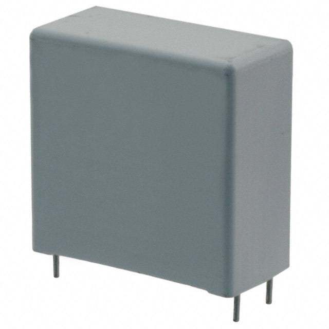
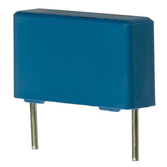
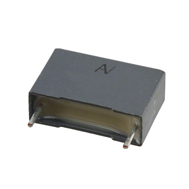
ICGOO电子元器件商城为您提供BFC233810104由Vishay设计生产,在icgoo商城现货销售,并且可以通过原厂、代理商等渠道进行代购。 BFC233810104价格参考。VishayBFC233810104封装/规格:薄膜电容器, 0.1µF 薄膜电容器 440V 1000V(1kV) 聚丙烯(PP),金属化 径向。您可以下载BFC233810104参考资料、Datasheet数据手册功能说明书,资料中有BFC233810104 详细功能的应用电路图电压和使用方法及教程。
Vishay BC Components的BFC233810104是一款薄膜电容器,广泛应用于需要高可靠性和稳定性的电子电路中。以下是其主要应用场景:

 1. 电源滤波
   - 在开关电源(SMPS)、逆变器和直流-直流转换器中,BFC233810104可用于输入/输出滤波,减少电磁干扰(EMI)和电压纹波,确保电源系统的稳定性。
   - 其低ESR(等效串联电阻)和低ESL(等效串联电感)特性使其非常适合高频滤波应用。

 2. 耦合与去耦
   - 用于信号耦合或去耦,特别是在射频(RF)和音频电路中,能够有效隔离直流成分并传递交流信号。
   - 在高速数字电路中,可作为去耦电容以抑制噪声,确保信号完整性。

 3. 能量存储与释放
   - 在脉冲功率系统(如激光器、闪光灯等)中,该电容器可以快速存储和释放能量,满足高功率瞬态需求。
   - 其高耐压特性和低损耗特性使其适用于高压储能场景。

 4. 谐振电路
   - 在LC谐振电路中(如无线电发射器、接收器和振荡器),BFC233810104因其高Q值和低介质损耗角,能够提供精确的频率选择性和高效的能量传输。

 5. 电机控制
   - 在电机驱动器和变频器中,该电容器可用于平滑直流母线电压、吸收再生能量以及抑制开关噪声。
   - 其优异的温度稳定性和耐久性适合工业自动化和家电领域。

 6. 汽车电子
   - 应用于车载电子系统(如引擎控制单元、LED照明驱动和信息娱乐系统),能够在极端温度和振动条件下保持性能稳定。
   - 满足汽车级可靠性要求,支持长时间运行。

 7. 医疗设备
   - 在医疗成像设备(如X射线机、超声波设备)中,BFC233810104可用于高压脉冲生成和信号处理,确保高精度和安全性。

 总结
BFC233810104凭借其高耐压能力(1000VDC)、低损耗和宽温度范围(-55°C至+105°C),在电力电子、通信、工业控制、汽车和医疗等领域具有广泛的适用性。其卓越的性能使其成为高性能应用的理想选择。
| 参数 | 数值 |
| 产品目录 | |
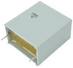
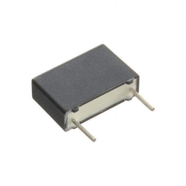
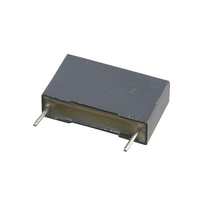
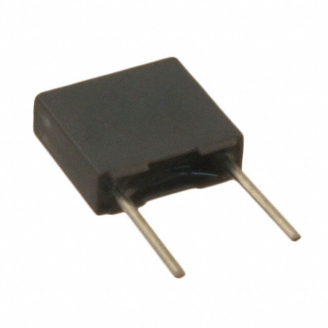
| 描述 | CAP FILM 0.1UF 1KVDC RADIAL薄膜电容器 .1uF 20% 440volts |
| ESR(等效串联电阻) | - |
| 产品分类 | |
| 品牌 | Vishay BC ComponentsVishay / BC Components |
| 产品手册 | |
| 产品图片 |
|
| rohs | 符合RoHS无铅 / 符合限制有害物质指令(RoHS)规范要求 |
| 产品系列 | 薄膜电容器,Vishay / BC Components BFC233810104MKP338 1 X1 |
| 数据手册 | |
| 产品型号 | BFC233810104BFC233810104 |
| 产品 | Safety Film Capacitors |
| 产品培训模块 | http://www.digikey.cn/PTM/IndividualPTM.page?site=cn&lang=zhs&ptm=24930 |
| 产品目录绘图 |
|
| 产品目录页面 | |
| 产品种类 | Radial Suppression Film Capacitor |
| 介电材料 | 聚丙烯(PP), 金属化 |
| 其它名称 | 2222 338 10104 |
| 包装 | 散装 |
| 商标 | Vishay / BC Components |
| 外壳宽度 | 10 mm |
| 外壳长度 | 17.5 mm |
| 外壳高度 | 16.5 mm |
| 大小/尺寸 | 0.689" 长 x 0.394" 宽(17.50mm x 10.00mm) |
| 安装类型 | 通孔 |
| 容差 | 20 %±20% |
| 封装/外壳 | 径向 |
| 工作温度 | -55°C ~ 105°C |
| 工厂包装数量 | 500 |
| 应用 | 通用 |
| 引线间距 | 0.591"(15.00mm) |
| 引线间隔 | 15 mm |
| 标准包装 | 500 |
| 特性 | - |
| 电介质 | Polypropylene (PP) |
| 电压额定值AC | 440 V |
| 电压额定值DC | 1 kV |
| 电容 | 0.1µF0.1 uF |
| 端接 | PC 引脚 |
| 端接类型 | Radial |
| 系列 | MKP338 |
| 零件号别名 | 222233810104 |
| 额定电压-AC | 440V |
| 额定电压-DC | 1000V(1kV) |
| 高度-安装(最大值) | 0.650"(16.50mm) |


- 商务部:美国ITC正式对集成电路等产品启动337调查
- 曝三星4nm工艺存在良率问题 高通将骁龙8 Gen1或转产台积电
- 太阳诱电将投资9.5亿元在常州建新厂生产MLCC 预计2023年完工
- 英特尔发布欧洲新工厂建设计划 深化IDM 2.0 战略
- 台积电先进制程称霸业界 有大客户加持明年业绩稳了
- 达到5530亿美元!SIA预计今年全球半导体销售额将创下新高
- 英特尔拟将自动驾驶子公司Mobileye上市 估值或超500亿美元
- 三星加码芯片和SET,合并消费电子和移动部门,撤换高东真等 CEO
- 三星电子宣布重大人事变动 还合并消费电子和移动部门
- 海关总署:前11个月进口集成电路产品价值2.52万亿元 增长14.8%

PDF Datasheet 数据手册内容提取
MKP338 1 X1 www.vishay.com Vishay BCcomponents Interference Suppression Film Capacitor - Class X1 Radial MKP 440 V - Standard Across the Line AC FEATURES • 15 mm to 27.5 mm lead pitch • 440 V rated AC voltage • Material categorization: for definitions of compliance please see www.vishay.com/doc?99912 APPLICATIONS For standard across the line X1 applications. See also application note: www.vishay.com/doc?28153 QUICK REFERENCE DATA 0.01 μF to 1 μF Capacitance range (E12 series) (referred values acc. to E6) Capacitance tolerance ± 20 %, ± 10 %, ± 5 % Rated AC voltage 440 V ; 50 Hz to 60 Hz AC Permissible DC voltage 1000 V DC 50/105/56/C for product volumes > 1750 mm3 Climatic testing class acc. to IEC 60068-1 50/105/56/B for volumes 1750 mm3 Maximum application temperature 105 °C IEC 60384-14 ed-4 (2013) and EN 60384-14 Reference standards IEC 60065 pass. flamm. class B for volumes > 1750 mm3 UL 60384-14 Dielectric Polypropylene film Electrodes Metallized film Mono construction Construction Encapsulation Plastic case, epoxy resin sealed, flame retardant UL-class 94 V-0 Leads Tinned wire C-value; tolerance; rated voltage; sub-class; manufacturer’s type; Marking code for dielectric material; manufacturer location, year and week; manufacturer’s logo or name; safety approvals Note • For more detailed data and test requirements, contact rfi@vishay.com DIMENSIONS l w h l t P Ø dt Revision: 21-Sep-16 1 Document Number: 28116 For technical questions, contact: rfi@vishay.com THIS DOCUMENT IS SUBJECT TO CHANGE WITHOUT NOTICE. THE PRODUCTS DESCRIBED HEREIN AND THIS DOCUMENT ARE SUBJECT TO SPECIFIC DISCLAIMERS, SET FORTH AT www.vishay.com/doc?91000
MKP338 1 X1 www.vishay.com Vishay BCcomponents COMPOSITION OF CATALOG NUMBER MULTIPLIER CAPACITANCE TYPE AND PITCHES (numerically) (nF) 15.0mm 0.1 2 3381 22.5mm Example: 1 3 X1 27.5mm 104=10x10=100nF 10 4 (except special numbers) 100 5 BFC2 338 1X XX X TYPE PACKAGING LEAD CONFIGURATION C-TOL. PREFERRED TYPES Lead length 3.5mm ± 0.3mm BFC2 338 10 ... 3381 Loose in box Lead length 5.0mm ± 1.0mm BFC2 338 12 ... ± 20 % Lead length 25.0mm ± 2.0mm BFC2 338 14 ... X1 Taped on reel (1) H=18.5mm; for P = 12.7 mm; reel diameter = 500 mm BFC2 338 17 ... 0 TYPE PACKAGING ALTERNATIVE C-TOL. C-TOL. ON REQUEST ± 10 % Lead length 3.5 mm ±0.3mm ± 5 % ± 10 % Loose in box Lead length 5.0 mm ±1.0mm 3381 ± 5 % See tables for detail X1 ± 10 % Lead length 25.0 mm ±2.0mm ± 5 % ± 10 % Taped on reel (1) H = 18.5 mm; P = 12.7 mm; reel diameter = 500 mm 0 ± 5 % Note (1) For detailed tape specification refer to packaging information: www.vishay.com/doc?28139 SPECIFIC REFERENCE DATA DESCRIPTION VALUE Rated AC voltage (U ) 440 V RAC Permissible DC voltage (U ) 1000 V RDC Tangent of loss angle: at 1 kHz at 10 kHz C 470 nF 10 x 10-4 20 x 10-4 C > 470 nF 20 x 10-4 70 x 10-4 Rated voltage pulse slope (dU/dt) at 615 V R DC Pitch = 15 mm 250 V/μs Pitch = 22.5 mm 150 V/μs Pitch = 27.5 mm 100 V/μs R between leads, for C 0.33 μF at 100 V, 1 min > 15 000 M RC between leads, for C > 0.33 μF at 100 V, 1 min > 5000 s R between leads and case, 100 V, 1 min > 30 000 M Withstanding (DC) voltage (cut off current 10 mA) (1), rise time 1000 V/s 3400 V, 1 min Withstanding (AC) voltage between leads and case 2380 V, 1 min Maximum application temperature 105 °C Note (1) See “Voltage Proof Test for Metallized Film Capacitors”: www.vishay.com/doc?28169 Revision: 21-Sep-16 2 Document Number: 28116 For technical questions, contact: rfi@vishay.com THIS DOCUMENT IS SUBJECT TO CHANGE WITHOUT NOTICE. THE PRODUCTS DESCRIBED HEREIN AND THIS DOCUMENT ARE SUBJECT TO SPECIFIC DISCLAIMERS, SET FORTH AT www.vishay.com/doc?91000
MKP338 1 X1 www.vishay.com Vishay BCcomponents ELECTRICAL DATA AND ORDERING INFORMATION CATALOG NUMBER BFC2 338 1XXXX AND PACKAGING DIMENSIONS LOOSE IN BOX TAPED REEL (1)(2) CAP. MASS URAC (μF) w x h x l (g) (3) SHORT LEADS LONG LEADS Ø = 500 mm (mm) l = 3.5 mm l = 5.0 mm l = 25.0 mm H = 18.5 mm; t t SPQ t SPQ SPQ ± 0.3 mm ± 1.0 mm ± 2.0 mm P = 12.7 mm 0 PITCH = 15.0 mm ± 0.4 mm; d = 0.60 mm ± 0.06 mm; C-tol. = ± 20 % t 0.010 10103 12103 14103 17103 0.012 10123 12123 14123 17123 0.015 5.0 x 11.0 x 17.5 1.0 10153 12153 1000 14153 1000 17153 1100 0.018 10183 12183 14183 17183 0.022 10223 12223 14223 17223 0.027 10273 12273 14273 17273 6.0 x 12.0 x 17.5 1.4 1000 1000 900 0.033 10333 12333 14333 17333 PITCH = 15.0 mm ± 0.4 mm; d = 0.80 mm ± 0.08 mm; C-tol. = ± 20 % t 0.039 10393 12393 14393 17393 7.0 x 13.5 x 17.5 1.8 750 500 800 0.047 10473 12473 14473 17473 0.056 10563 12563 14563 17563 8.5 x 15.0 x 17.5 2.4 750 500 650 0.068 10683 12683 14683 17683 0.082 10823 12823 14823 17823 10.0 x 16.5 x 17.5 3.0 500 450 600 0.10 10104 12104 14104 17104 PITCH = 22.5 mm ± 0.4 mm; d = 0.80 mm ± 0.08 mm; C-tol. = ± 20 % t 0.12 10124 12124 14124 17124 8.5 x 18.0 x 26.0 3.8 200 250 450 0.15 10154 12154 14154 17154 0.18 10184 12184 14184 17184 10.0 x 19.5 x 26.0 6.8 200 200 350 0.22 10224 12224 14224 17224 PITCH = 27.5 mm ± 0.4 mm; d = 0.80 mm ± 0.08 mm; C-tol. = ± 20 % t 440 0.27 11.0 x 21.0 x 31.0 7.4 10274 12274 100 14274 125 0.33 13.0 x 23.0 x 31.0 9.2 10334 12334 100 14334 125 0.39 10394 12394 14394 15.0 x 25.0 x 31.5 12.3 100 125 0.47 10474 12474 14474 - - 0.56 10564 12564 14564 18.0 x 28.0 x 31.5 16.1 100 100 0.68 10684 12684 14684 0.82 10824 12824 14824 21.0 x 31.0 x 31.0 20.3 50 75 1.00 10105 12105 14105 PITCH = 15.0 mm ± 0.4 mm; d = 0.60 mm ± 0.06 mm; C-tol. = ± 10 % t 0.010 18114 18314 18514 18914 0.012 18115 18315 18515 18915 5.0 x 11.0 x 17.5 1.0 1000 1000 1100 0.015 18116 18316 18516 18916 0.018 18117 18317 18517 18917 0.022 18118 18318 18518 18918 6.0 x 12.0 x 17.5 1.4 1000 1000 900 0.027 18119 18319 18519 18919 PITCH = 15.0 mm ± 0.4 mm; d = 0.80 mm ± 0.08 mm; C-tol. = ± 10 % t 0.033 18121 18321 18521 18921 7.0 x 13.5 x 17.5 1.8 750 500 800 0.039 18122 18322 18522 18922 0.047 18123 18323 18523 18923 8.5 x 15.0 x 17.5 2.4 750 500 650 0.056 18124 18324 18524 18924 0.068 18125 18325 18525 18925 10.0 x 16.5 x 17.5 3.0 500 450 600 0.082 18126 18326 18526 18926 Revision: 21-Sep-16 3 Document Number: 28116 For technical questions, contact: rfi@vishay.com THIS DOCUMENT IS SUBJECT TO CHANGE WITHOUT NOTICE. THE PRODUCTS DESCRIBED HEREIN AND THIS DOCUMENT ARE SUBJECT TO SPECIFIC DISCLAIMERS, SET FORTH AT www.vishay.com/doc?91000
MKP338 1 X1 www.vishay.com Vishay BCcomponents ELECTRICAL DATA AND ORDERING INFORMATION CATALOG NUMBER BFC2 338 1XXXX AND PACKAGING DIMENSIONS LOOSE IN BOX TAPED REEL (1)(2) CAP. MASS URAC (μF) w x h x l (g) (3) SHORT LEADS LONG LEADS Ø = 500 mm (mm) l = 3.5 mm l = 5.0 mm l = 25.0 mm H = 18.5 mm; t t SPQ t SPQ SPQ ± 0.3 mm ± 1.0 mm ± 2.0 mm P = 12.7 mm 0 PITCH = 22.5 mm ± 0.4 mm; d = 0.80 mm ± 0.08 mm; C-tol. = ± 10 % t 0.10 7.0 x 16.5 x 26.0 2.9 18127 18327 200 18527 250 18927 550 0.12 18128 18328 18528 18928 8.5 x 18.0 x 26.0 3.8 200 250 450 0.15 18129 18329 18529 18929 0.18 10.0 x 19.5 x 26.0 6.8 18131 18331 200 18531 200 18931 350 PITCH = 27.5 mm ± 0.4 mm; d = 0.80 mm ± 0.08 mm; C-tol. = ± 10 % t 0.22 18132 18332 18532 11.0 x 21.0 x 31.0 7.4 100 125 0.27 18133 18333 18533 0.33 13.0 x 23.0 x 31.0 9.2 18134 18334 100 18534 125 0.39 18135 18335 18535 15.0 x 25.0 x 31.0 12.3 100 125 - - 0.47 18136 18336 18536 0.56 18137 18337 18537 18.0 x 28.0 x 31.0 16.1 100 100 0.68 18138 18338 18538 0.82 21.0 x 31.0 x 31.0 20.3 18139 18339 50 18539 75 PITCH = 15.0 mm ± 0.4 mm; d = 0.60 mm ± 0.06 mm; C-tol. = ± 5 % t 0.010 18214 18414 18614 18934 0.012 18215 18415 18615 18935 5.0 x 11.0 x 17.5 1.0 1000 1000 1100 0.015 18216 18416 18616 18936 0.018 18217 18417 18617 18937 0.022 18218 18418 18618 18938 6.0 x 12.0 x 17.5 1.4 1000 1000 900 0.027 18219 18419 18619 18939 440 PITCH = 15.0 mm ± 0.4 mm; d = 0.80 mm ± 0.08 mm; C-tol. = ± 5 % t 0.033 18221 18421 18621 18941 7.0 x 13.5 x 17.5 1.8 750 500 800 0.039 18222 18422 18622 18942 0.047 18223 18423 18623 18943 8.5 x 15.0 x 17.5 2.4 750 500 650 0.056 18224 18424 18624 18944 0.068 18225 18425 18625 18945 10.0 x 16.5 x 17.5 3.0 500 450 600 0.082 18226 18426 18626 18946 PITCH = 22.5 mm ± 0.4 mm; d = 0.80 mm ± 0.08 mm; C-tol. = ± 5 % t 0.10 18227 18427 18627 18947 8.5 x 18.0 x 26.0 3.8 200 250 450 0.12 18228 18428 18628 18948 0.15 18229 18429 18629 18949 10.0 x 19.5 x 26.0 6.8 200 200 350 0.18 18231 18431 18631 18951 PITCH = 27.5 mm ± 0.4 mm; d = 0.80 mm ± 0.08 mm; C-tol. = ± 5 % t 0.22 11.0 x 21.0 x 31.0 7.4 18232 18432 100 18632 125 0.27 18233 18433 18633 13.0 x 23.0 x 31.0 9.2 100 125 0.33 18234 18434 18634 0.39 18235 18435 18635 15.0 x 25.0 x 31.5 12.3 100 125 - - 0.47 18236 18436 18636 0.56 18237 18437 18637 18.0 x 28.0 x 31.5 16.1 100 100 0.68 18238 18438 18638 0.82 21.0 x 31.0 x 31.0 20.3 18239 18439 50 18639 75 Notes • SPQ = Standard Packing Quantity (1) H = in-tape height; P = sprocket hole distance; for detailed specifications refer to packaging information: www.vishay.com/doc?28139 0 (2) Reel diameter = 356 mm is available on request (3) Weight for short lead product only Revision: 21-Sep-16 4 Document Number: 28116 For technical questions, contact: rfi@vishay.com THIS DOCUMENT IS SUBJECT TO CHANGE WITHOUT NOTICE. THE PRODUCTS DESCRIBED HEREIN AND THIS DOCUMENT ARE SUBJECT TO SPECIFIC DISCLAIMERS, SET FORTH AT www.vishay.com/doc?91000
MKP338 1 X1 www.vishay.com Vishay BCcomponents APPROVALS SAFETY APPROVALS X1 VOLTAGE VALUE FILE NUMBERS LINKS EN 60384-14 (ENEC) 440 V 10 nF to 1 μF FI 2016037 www.vishay.com/doc?28202 (= IEC 60384-14 ed-4 (2013)) AC UL 60384-14 440 V 10 nF to 1 μF E354331 AC www.vishay.com/doc?28190 CSA E384-14 440 V 10 nF to 1 μF E354331 AC CB-test certificate 440 V 10 nF to 1 μF FI 9218 www.vishay.com/doc?28201 AC The ENEC-approval together with the CB-certificate replace all national marks of the following countries (they have already signed the ENEC-agreement): Austria; Belgium; Czech. Republic; Denmark; Finland; France; Germany; Greece; Hungary; Ireland; Italy; Luxembourg; Netherlands; Norway; Portugal; Slovenian; Spain; Switzerland and United Kingdom. MOUNTING Normal Use The capacitors are designed for mounting on printed-circuit boards. The capacitors packed in bandoliers are designed for mounting in printed-circuit boards by means of automatic insertion machines. For detailed tape specifications refer to packaging information: www.vishay.com/doc?28139 Specific Method of Mounting to Withstand Vibration and Shock In order to withstand vibration and shock tests, it must be ensured that the stand-off pips are in good contact with the printed-circuit board: • For pitches 15 mm capacitors shall be mechanically fixed by the leads • For longer pitches the capacitors shall be mounted in the same way and the body clamped Space Requirements on Printed Circuit Board The maximum space for length (I ), width (w ) and height (h ) of film capacitors to take in account on the printed circuit max. max. max. board is shown in the drawings. • For products with pitch 15 mm, w =l = 0.3 mm; h = 0.1 mm Eccentricity defined as in drawing. The maximum eccentricity is smaller than or equal to the lead diameter of the product concerned. w = W + Δ max. Eccentricity I = I + Δ CBA116 max. h = h + Δ max. Seating plane SOLDERING For general soldering conditions and wave soldering profile, we refer to the application note: “Soldering Guidelines for Film Capacitors”: www.vishay.com/doc?28171 Storage Temperature T = -25 °C to +35 °C with RH maximum 75 % without condensation stg Ratings and Characteristics Reference Conditions Unless otherwise specified, all electrical values apply to an ambient temperature of 23 °C ± 1 °C, an atmospheric pressure of 86 kPa to 106 kPa and a relative humidity of 50 % ± 2 %. For reference testing, a conditioning period shall be applied over 96 h ± 4 h by heating the products in a circulating air oven at the rated temperature and a relative humidity not exceeding 20 %. Revision: 21-Sep-16 5 Document Number: 28116 For technical questions, contact: rfi@vishay.com THIS DOCUMENT IS SUBJECT TO CHANGE WITHOUT NOTICE. THE PRODUCTS DESCRIBED HEREIN AND THIS DOCUMENT ARE SUBJECT TO SPECIFIC DISCLAIMERS, SET FORTH AT www.vishay.com/doc?91000
MKP338 1 X1 www.vishay.com Vishay BCcomponents CHARACTERISTICS 4 103 ΔC/C (%)2 typical Dissipation - 4Factor (x 10) 0 102 C = <1 1µµFF - 2 max. 101 1407 2n 2nF0F <n< F C C< ≤ ≤ C 4 272 n0 FnF - 4 min. - 6 - 50 0 50 T (°C) 100 100101 102 103 104 f(Hz) 105 amb Capacitance as a function of ambient temperature Tangent of loss angle as a function of frequency (typical curve) (typical curve) e103 102 c ImpedanΩ1 ()02 47 n1F0 nF f (Mhz)101 110001 10407010 0n 0nF FnF 100 X 1 10-1 10-2 10-1 104 105 106 107 f (Hz) 108 1 10 100 1000 °C (nF)10 00 0 Impedance as a function of frequency Resonant frequency as a function of capacitance (typical curve) (typical curve) 103 104 nt AC voltage (V) AC curre (mA)110032 1401700000 n nnFFF 47 nF 102 101 10 nF 4.7 nF 100 1 nF T ≤ 105 °C amb T ≤ 105 °C amb 101 10-1 101 102 103 104 f (Hz) 105 101 102 103 104 f (Hz) 105 Max. RMS voltage as a function of frequency Max. RMS current as a function of frequency Revision: 21-Sep-16 6 Document Number: 28116 For technical questions, contact: rfi@vishay.com THIS DOCUMENT IS SUBJECT TO CHANGE WITHOUT NOTICE. THE PRODUCTS DESCRIBED HEREIN AND THIS DOCUMENT ARE SUBJECT TO SPECIFIC DISCLAIMERS, SET FORTH AT www.vishay.com/doc?91000
MKP338 1 X1 www.vishay.com Vishay BCcomponents 106 s) C ( R 105 104 0 20 40 60 80 100 Tamb (°C) Insulation resistance as a function of ambient temperature APPLICATION NOTES • For X1 electromagnetics interference suppression in standard across the line applications (50 Hz/60 Hz) with a maximum mains voltage of 440 V . AC • For series impedance applications we refer to application note: www.vishay.com/doc?28153 • For capacitors connected in parallel, normally the proof voltage and possibly the rated voltage must be reduced. For information depending of the capacitance value and the number of parallel connections contact: rfi@vishay.com • These capacitors are not intended for continuous pulse applications. For these situations, capacitors of the AC and pulse programs must be used. • The maximum ambient temperature must not exceed 105 °C. • Rated voltage pulse slope: If the pulse voltage is lower than the rated voltage, the values of the specific reference data can be multiplied by 615 V and DC divided by the applied voltage. INSPECTION REQUIREMENTS General Notes Sub-clause numbers of tests and performance requirements refer to the “Sectional Specification, Publication IEC 60384-14 ed-3 and Specific Reference Data”. GROUP C INSPECTION REQUIREMENTS SUB-CLAUSE NUMBER AND TEST CONDITIONS PERFORMANCE REQUIREMENTS SUB-GROUP C1A PART OF SAMPLE OF SUB-GROUP C1 4.1 Dimensions (detail) As specified in chapters “General data” of this specification Initial measurements Capacitance Tangent of loss angle at 10 kHz 4.3 Robustness of terminations Tensile: Load 10 N; 10 s No visible damage Bending: Load 5 N; 4 x 90° 4.4 Resistance to soldering heat No pre-drying Method: 1A Solder bath: 280 °C ± 5 °C Duration: 10 s Revision: 21-Sep-16 7 Document Number: 28116 For technical questions, contact: rfi@vishay.com THIS DOCUMENT IS SUBJECT TO CHANGE WITHOUT NOTICE. THE PRODUCTS DESCRIBED HEREIN AND THIS DOCUMENT ARE SUBJECT TO SPECIFIC DISCLAIMERS, SET FORTH AT www.vishay.com/doc?91000
MKP338 1 X1 www.vishay.com Vishay BCcomponents GROUP C INSPECTION REQUIREMENTS SUB-CLAUSE NUMBER AND TEST CONDITIONS PERFORMANCE REQUIREMENTS SUB-GROUP C1A PART OF SAMPLE OF SUB-GROUP C1 4.19 Component solvent resistance Isopropylalcohol at room temperature Method: 2 Immersion time: 5 min ± 0.5 min Recovery time: Min. 1 h, max. 2 h 4.4.2 Final measurements Visual examination No visible damage Legible marking Capacitance |C/C| 5 % of the value measured initially Tangent of loss angle Increase of tan 0.008 Compared to values measured initially Insulation resistance As specified in section “Insulation Resistance” of this specification SUB-GROUP C1B PART OF SAMPLE OF SUB-GROUP C1 Initial measurements Capacitance Tangent of loss angle at 10 kHz 4.20 Solvent resistance of the marking Isopropylalcohol at room temperature No visible damage Method: 1 Legible marking Rubbing material: Cotton wool Immersion time: 5 min ± 0.5 min 4.6 Rapid change of temperature A = - 55 °C B = + 105 °C 5 cycles Duration t = 30 min 4.6.1 Inspection Visual examination No visible damage 4.7 Vibration Mounting: See section “Mounting” of this specification Procedure B4 Frequency range: 10 Hz to 55 Hz Amplitude: 0.75 mm or acceleration 98 m/s2 (whichever is less severe) Total duration: 6 h 4.7.2 Final inspection Visual examination No visible damage 4.9 Shock Mounting: See section “Mounting” for more information Pulse shape: Half sine Acceleration: 490 m/s2 Duration of pulse: 11 ms 4.9.2 Final measurements Visual examination No visible damage Capacitance |C/C| 5 % of the value measured initially Tangent of loss angle Increase of tan 0.008 Compared to values measured initially Insulation resistance As specified in section “Insulation Resistance” of this specification Revision: 21-Sep-16 8 Document Number: 28116 For technical questions, contact: rfi@vishay.com THIS DOCUMENT IS SUBJECT TO CHANGE WITHOUT NOTICE. THE PRODUCTS DESCRIBED HEREIN AND THIS DOCUMENT ARE SUBJECT TO SPECIFIC DISCLAIMERS, SET FORTH AT www.vishay.com/doc?91000
MKP338 1 X1 www.vishay.com Vishay BCcomponents GROUP C INSPECTION REQUIREMENTS SUB-CLAUSE NUMBER AND TEST CONDITIONS PERFORMANCE REQUIREMENTS SUB-GROUP C1 COMBINED SAMPLE OF SPECIMENS OF SUB-GROUPS C1A AND C1B 4.11 Climatic sequence 4.11.1 Initial measurements Capacitance Measured in 4.4.2 and 4.9.2 Tangent of loss angle Measured initially in C1A and C1B 4.11.2 Dry heat Temperature: 105 °C Duration: 16 h 4.11.3 Damp heat cyclic Test Db First cycle 4.11.4 Cold Temperature: - 55 °C Duration: 2 h 4.11.5 Damp heat cyclic Test Db Remaining cycles 4.11.6 Final measurements Visual examination No visible damage Legible marking Capacitance |C/C| 5 % of the value measured in 4.11.1. Tangent of loss angle Increase of tan 0.008 Compared to values measured in 4.11.1. Voltage proof No permanent breakdown or flash-over 1900 VDC; 1 min between terminations Insulation resistance 50 % of values specified in section “Insulation Resistance” of this specification SUB-GROUP C2 4.12 Damp heat steady state 56 days, 40 °C, 90 % to 95 % RH No load 4.12.1 Initial measurements Capacitance Tangent of loss angle at 1 kHz 4.12.3 Final measurements Visual examination No visible damage Legible marking Capacitance |C/C| 5 % of the value measured in 4.12.1. Tangent of loss angle Increase of tan 0.008 Compared to values measured in 4.12.1. Voltage proof No permanent breakdown or flash-over 1900 VDC; 1 min between terminations Insulation resistance 50 % of values specified in section “Insulation Resistance” of this specification Revision: 21-Sep-16 9 Document Number: 28116 For technical questions, contact: rfi@vishay.com THIS DOCUMENT IS SUBJECT TO CHANGE WITHOUT NOTICE. THE PRODUCTS DESCRIBED HEREIN AND THIS DOCUMENT ARE SUBJECT TO SPECIFIC DISCLAIMERS, SET FORTH AT www.vishay.com/doc?91000
MKP338 1 X1 www.vishay.com Vishay BCcomponents GROUP C INSPECTION REQUIREMENTS SUB-CLAUSE NUMBER AND TEST CONDITIONS PERFORMANCE REQUIREMENTS SUB-GROUP C3 4.13.1 Initial measurements Capacitance Tangent of loss angle at 10 kHz 4.13 Impulse voltage 3 successive impulses, full wave, peak No self healing breakdowns or flash-over voltage: X1: 4 kV Max. 24 pulses 4.14 Endurance Duration: 1000 h 1.25 x U at 105 °C RAC Once in every hour the voltage is increased to 1000 VRMS for 0.1 s via resistor of 47 ± 5 % 4.14.7 Final measurements Visual examination No visible damage Legible marking Capacitance |C/C| 10 % compared to values measured in 4.13.1. Tangent of loss angle Increase of tan 0.008 Compared to values measured in 4.13.1. Voltage proof No permanent breakdown or flash-over 1900 V ; 1 min between terminations DC 2380 VAC; 1 min between terminations and case. Insulation resistance 50 % of values specified in section “Insulation Resistance” of this specification SUB-GROUP C4 4.15 Charge and discharge 10 000 cycles Charged to 615 VDC Discharge resistance: 615 V R = -------------------------D----C----------- 1.5 x C (dU/dt) 4.15.1 Initial measurements Capacitance Tangent of loss angle at 10 kHz 4.15.3 Final measurements Capacitance |C/C| 10 % compared to values measured in 4.15.1. Tangent of loss angle Increase of tan 0.008 Compared to values measured in 4.15.1. Insulation resistance 50 % of values specified in section “Insulation Resistance” of this specification SUB-GROUP C5 4.16 Radio frequency characteristic Resonance frequency 0.9 times value as specified in section “Resonant Frequency” of this specification Revision: 21-Sep-16 10 Document Number: 28116 For technical questions, contact: rfi@vishay.com THIS DOCUMENT IS SUBJECT TO CHANGE WITHOUT NOTICE. THE PRODUCTS DESCRIBED HEREIN AND THIS DOCUMENT ARE SUBJECT TO SPECIFIC DISCLAIMERS, SET FORTH AT www.vishay.com/doc?91000
MKP338 1 X1 www.vishay.com Vishay BCcomponents GROUP C INSPECTION REQUIREMENTS SUB-CLAUSE NUMBER AND TEST CONDITIONS PERFORMANCE REQUIREMENTS SUB-GROUP C6 4.17 Passive flammability Bore of gas jet: Ø 0.5 mm After removing test flame from capacitor, the Class B Fuel: Butane capacitor must not continue to burn for more Test duration for actual volume V in mm3: than 10 s. No burning particle must drop V 250: 10 s from the sample. 250 < V 500: 20 s 500 < V 1750: 30 s V > 1750: 60 s One flame application 12 mm ~ 8 mm 45.0° SUB-GROUP C7 4.18 Active flammability 20 cycles of 4 kV discharges on the test The cheese cloth around the capacitors shall capacitor connected to U . not burn with a flame. RAC No electrical measurements are required. Revision: 21-Sep-16 11 Document Number: 28116 For technical questions, contact: rfi@vishay.com THIS DOCUMENT IS SUBJECT TO CHANGE WITHOUT NOTICE. THE PRODUCTS DESCRIBED HEREIN AND THIS DOCUMENT ARE SUBJECT TO SPECIFIC DISCLAIMERS, SET FORTH AT www.vishay.com/doc?91000
Legal Disclaimer Notice www.vishay.com Vishay Disclaimer ALL PRODUCT, PRODUCT SPECIFICATIONS AND DATA ARE SUBJECT TO CHANGE WITHOUT NOTICE TO IMPROVE RELIABILITY, FUNCTION OR DESIGN OR OTHERWISE. Vishay Intertechnology, Inc., its affiliates, agents, and employees, and all persons acting on its or their behalf (collectively, “Vishay”), disclaim any and all liability for any errors, inaccuracies or incompleteness contained in any datasheet or in any other disclosure relating to any product. Vishay makes no warranty, representation or guarantee regarding the suitability of the products for any particular purpose or the continuing production of any product. To the maximum extent permitted by applicable law, Vishay disclaims (i) any and all liability arising out of the application or use of any product, (ii) any and all liability, including without limitation special, consequential or incidental damages, and (iii) any and all implied warranties, including warranties of fitness for particular purpose, non-infringement and merchantability. Statements regarding the suitability of products for certain types of applications are based on Vishay’s knowledge of typical requirements that are often placed on Vishay products in generic applications. Such statements are not binding statements about the suitability of products for a particular application. It is the customer’s responsibility to validate that a particular product with the properties described in the product specification is suitable for use in a particular application. Parameters provided in datasheets and / or specifications may vary in different applications and performance may vary over time. All operating parameters, including typical parameters, must be validated for each customer application by the customer’s technical experts. Product specifications do not expand or otherwise modify Vishay’s terms and conditions of purchase, including but not limited to the warranty expressed therein. Except as expressly indicated in writing, Vishay products are not designed for use in medical, life-saving, or life-sustaining applications or for any other application in which the failure of the Vishay product could result in personal injury or death. Customers using or selling Vishay products not expressly indicated for use in such applications do so at their own risk. Please contact authorized Vishay personnel to obtain written terms and conditions regarding products designed for such applications. No license, express or implied, by estoppel or otherwise, to any intellectual property rights is granted by this document or by any conduct of Vishay. Product names and markings noted herein may be trademarks of their respective owners. © 2017 VISHAY INTERTECHNOLOGY, INC. ALL RIGHTS RESERVED Revision: 08-Feb-17 1 Document Number: 91000
Mouser Electronics Authorized Distributor Click to View Pricing, Inventory, Delivery & Lifecycle Information: V ishay: BFC233814104 BFC233810683 BFC233814473 BFC233816223 BFC233814474 BFC233812104 BFC233814153 BFC233810684 BFC233812474 BFC233816153 BFC233816683 BFC233812473 BFC233817333 BFC233814684 BFC233812224 BFC233817103 BFC233814683 BFC233812223 BFC233816333 BFC233814223 BFC233817683 BFC233814333 BFC233816473 BFC233817154 BFC233812154 BFC233812683 BFC233817153 BFC233814334 BFC233812334 BFC233812333 BFC233812684 BFC233816103 BFC233814103 BFC233817473 BFC233814105 BFC233812103 BFC233814224 BFC233816104 BFC233814154 BFC233812105 BFC233817104 BFC233812153 BFC233817224 BFC233817223 BFC233810153 BFC233810104 2222-809-05217 BFC233810103 BFC233810105 BFC233810333 BFC233810334 BFC233810474 BFC233810154 BFC233810223 BFC233810224 BFC233810473