首页 > BD0205F5050AHF > 详情
 Datasheet下载
- 型号: BD0205F5050AHF
- 制造商: Anaren Microwave
- 库位|库存: xxxx|xxxx
- 要求:
| 数量阶梯 | 香港交货 | 国内含税 |
| +xxxx | $xxxx | ¥xxxx |
查看当月历史价格
查看今年历史价格
产品参数
| 参数 | 数值 |
| 产品目录 | 射频/IF 和 RFID无源元件 |
| 描述 | XFRMR BALUN RF 70-1000MHZ 1608信号调节 200-500MHz 50 Ohm IL +1.1dB |
| 产品分类 | 平衡-不平衡变压器信号调节 |
| 品牌 | Anaren |
| 产品手册 | 点击此处下载产品Datasheet |
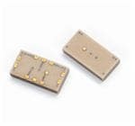
| 产品图片 |  .jpg) |
| rohs | 符合RoHS无铅 / 符合限制有害物质指令(RoHS)规范要求 |
| 产品系列 | Anaren BD0205F5050AHFXinger® |
| mouser_ship_limit | 该产品可能需要其他文件才能进口到中国。 |
| 数据手册 | 点击此处下载产品Datasheet |
| 产品型号 | BD0205F5050AHF |
| RoHS指令信息 | 点击此处下载产品Datasheet |
| 产品 | Baluns |
| 产品种类 | 信号调节 |
| 介入损耗 | 3 dB |
| 其它名称 | 1173-1072-1 |
| 包装 | 剪切带 (CT) |
| 商标 | Anaren |
| 商标名 | Xinger |
| 回波损耗(最小值) | 4dB |
| 安装类型 | 表面贴装 |
| 封装 | Reel |
| 封装/外壳 | 1608(4121 公制) |
| 封装/箱体 | 1608 (4121metric) |
| 工作温度范围 | - 55 C to + 85 C |
| 工厂包装数量 | 4000 |
| 插入损耗(最大值) | 3.4dB |
| 标准包装 | 1 |
| 相位差 | 1° |
| 端接类型 | SMD/SMT |
| 类型 | Ultral Low Profile Balun |
| 阻抗 | 50 Ohms |
| 阻抗-非平衡/平衡 | 50 / 50 欧姆 |
| 频率范围 | 70MHz ~ 1GHz |
Datasheet
PDF Datasheet 数据手册内容提取
Model BD0205F5050AHF Rev B Ultra Low Profile 1608 Balun 50Ω to 50Ω Balanced Description The BD0205F5050AHF is a low profile sub-miniature balanced to unbalanced transformer designed for differential input locations on data conversion devices such as A to D and D to A converters. In an easy to use surface mount package covering 75 MHz to 1000 MHz and with CMRR performances over 2x that of the incumbent wire wound products, this transformer is optimized to offer improved SFDR management during operation of the data converter device. The BD0205F5050AHF is ideal for high volume manufacturing and is higher performance and smaller form factor than traditional wire wound transformers. The BD0205F5050AHF has an unbalanced port impedance of 50Ω and a 50Ω balanced port impedance. This transformation enables single ended signals to be applied to differential ports on the data converter devices. The output ports have equal amplitude (-3dB) with 180 degree phase differential. The BD0205F5050AHF is available on tape and reel for pick and place high volume manufacturing. Detailed Electrical Specifications: Specifications subject to change without notice. ROOM (25°°°°C) Features: Parameter Min. Typ. Max Min. Typ. Max Unit • 70 – 1000 MHz (IL 3dB BW) Frequency 70 1000 200 500 MHz • 200-500 MHz ( IL 1dB BW) Unbalanced Port Impedance 50 50 Ohm • 0.83 mm Height Profile • 50 Ohm to 2 x 25 Ohm Balanced Port Impedance 50 50 Ohm • Excellent CMRR (36dB typical) Return Loss 4 4.6 11 13 dB • Input to Output DC Isolation Insertion Loss* 3.0 3.4 0.9 1.1 dB • Surface Mountable Amplitude Balance 0.2 0.6 0.2 0.6 dB • Tape & Reel Phase Balance 1 3 1 3 Degrees • Non-conductive Top Surface • RoHS Compliant CMRR 36 36 dB • Halogen Free Power Handling 2 2 Watts Operating Temperature -55 +85 -55 +85 ºC * Insertion Loss stated at room temperature (Insertion Loss is approximately 0.1 dB higher at +85 ºC) Outline Drawing Top View (Near-side) Side View Bottom View (Far-side) 1 2 3 4.10±.10 .84±.08 4x .96 10 4 2.10±.10 9 2x .35 5 4x .35 4x .28 Orientation Orientation 10x .30 Marker Marker 10x .22 8 7 6 PinDesignation PinDesignation 1 Unbalanced 6 Balanced port 1 2 OPEN 7 Open Mechanical Outline 3 GND 8 Balanced port 2 Dimensions are in Millimeters 4 GND 9 GND 5 GND 10 GND USA/Canada: (315) 432-8909 Visit us at Toll Free: (800) 411-6596 www.anaren.com Europe: +44 2392-232392 Asia: +86 512-62749282
Model BD0205F5050AHF Rev. B Typical Broadband Performance: 0 - 8.0 GHz. Return Loss - Input Insertion Loss 0 0 -3 -0.3 -6 -0.6 -9 -0.9 -12 -1.2 -15 -1.5 dB]-18 dB]-1.8 [ [ -21 -2.1 -24 -2.4 -27 -2.7 -30 -3 -33 -3.3 -36 -3.6 0 0 0 0 0 0 0 0 0 0 0 0 0 0 0 0 0 0 0 0 0 0 0 0 0 0 0 0 0 0 0 0 0 0 0 0 0 0 0 0 0 0 0 0 0 0 0 0 0 0 0 0 0 0 0 0 0 0 0 0 0 0 0 0 0 0 5 0 5 0 5 0 5 0 5 0 5 0 5 0 5 0 5 0 5 0 5 0 5 0 5 0 5 0 5 0 5 0 1 1 2 2 3 3 4 4 5 5 6 6 7 7 8 1 1 2 2 3 3 4 4 5 5 6 6 7 7 8 Frequency [MHz] Frequency [MHz] Amplitude Balance Phase Balance 2 20 1.5 15 1 10 0.5 5 [dB] 0 deg 0 -0.5 -5 -1 -10 -1.5 -15 -2 -20 0 0 0 0 0 0 0 0 0 0 0 0 0 0 0 0 0 0 0 0 0 0 0 0 0 0 0 0 0 0 0 0 0 0 0 0 0 0 0 0 0 0 0 0 0 0 0 0 0 0 0 0 0 0 0 0 0 0 0 0 0 0 0 0 0 0 5 0 5 0 5 0 5 0 5 0 5 0 5 0 5 0 5 0 5 0 5 0 5 0 5 0 5 0 5 0 5 0 1 1 2 2 3 3 4 4 5 5 6 6 7 7 8 1 1 2 2 3 3 4 4 5 5 6 6 7 7 8 Frequency [MHz] Frequency [MHz] CMRR -2 -5 -8 -11 -14 -17 -20 B]-23 [d--2296 -32 -35 -38 -41 -44 -47 -50 0 0 0 0 0 0 0 0 0 0 0 0 0 0 0 0 0 0 0 0 0 0 0 0 0 0 0 0 0 0 0 0 0 5 0 5 0 5 0 5 0 5 0 5 0 5 0 5 0 1 1 2 2 3 3 4 4 5 5 6 6 7 7 8 Frequency [MHz] USA/Canada: (315) 432-8909 Visit us at Toll Free: (800) 411-6596 www.anaren.com Europe: +44 2392-232392 Asia: +86 512-62749282
Model BD0205F5050AHF Rev B Typical Performance: 0 MHz. to 1000 MHz. Return Loss - Input Insertion Loss 0 0 -3 -0.3 -6 -0.6 -9 -0.9 -12 -1.2 -15 -1.5 B]-18 B]-1.8 d d [-21 [-2.1 -24 -2.4 -27 -2.7 -30 -3 -33 -3.3 -36 -3.6 0 50 100 150 200 250 300 350 400 450 500 550 600 650 700 750 800 850 900 950 1000 0 50 100 150 200 250 300 350 400 450 500 550 600 650 700 750 800 850 900 950 1000 Frequency [MHz] Frequency [MHz] Amplitude Balance Phase Balance 2 20 1.5 15 1 10 0.5 5 [dB] 0 deg 0 -0.5 -5 -1 -10 -1.5 -15 -2 -20 0 0 0 0 0 0 0 0 0 0 0 0 0 0 0 0 0 0 0 0 0 0 0 0 0 0 0 0 0 0 0 0 0 0 0 0 0 0 0 0 0 0 5 0 5 0 5 0 5 0 5 0 5 0 5 0 5 0 5 0 5 0 5 0 5 0 5 0 5 0 5 0 5 0 5 0 5 0 5 0 5 0 1 1 2 2 3 3 4 4 5 5 6 6 7 7 8 8 9 9 0 1 1 2 2 3 3 4 4 5 5 6 6 7 7 8 8 9 9 0 1 1 Frequency [MHz] Frequency [MHz] CMRR 0 -6 -12 -18 -24 -30 B]-36 [d -42 -48 -54 -60 -66 -72 0 0 0 0 0 0 0 0 0 0 0 0 0 0 0 0 0 0 0 0 0 5 0 5 0 5 0 5 0 5 0 5 0 5 0 5 0 5 0 5 0 1 1 2 2 3 3 4 4 5 5 6 6 7 7 8 8 9 9 0 1 Frequency [MHz] USA/Canada: (315) 432-8909 Visit us at Toll Free: (800) 411-6596 www.anaren.com Europe: +44 2392-232392 Asia: +86 512-62749282
Model BD0205F5050AHF Rev. B Application in ADC Frontend: Modern Analog-to-Digital Converter (ADC) system often uses differential architecture to suppress the even-order harmonics. The performance of ADC system is heavily influenced by amplitude and phase imbalances arising from the ADC frontend, especially in high frequency applications. Anaren’s multi-layer balun BD0205F5050AHF offers superb amplitude and phase balance performance over wide frequency range, translating to excellent SFDR performance of the ADC system. BD0205F5050AHF is a ferrite free design eliminating related inter-modulation and other non-linear effects. BD0205F5050AHF provides wideband impedance match, resulting in improvement of gain flatness at high frequencies, which in turn reduces input drive requirement. Anaren’s highly repeatable manufacturing process results in little part to part variation, ensuring consistent performance in production. The schematic of a typical ADC front end application is shown below. In conjunction with many high speed ADC ICs, a bandwidth of 70MHz to 250MHz can be obtained for -1dB ripple of gain flatness. Differential load R1 and R2 are 33 ohm, slightly higher than the theoretical 25 ohm, to increase the voltage gain and reduce the required input drive, while keeping acceptable return loss. Optional series resistors, R5, R6, R7 and R8 are used to limit the amount of charge injection from the unbuffered ADC back into the analog input. Optional RC circuits, R3, R4, C4 and C5 further improve SDFR in many circumstances by supplying an additional current path to neutralize the charge injection. Anaren Balun BD0205F5050AHF Typical ADC frontend schematic using BD0205F5050AHF USA/Canada: (315) 432-8909 Visit us at Toll Free: (800) 411-6596 www.anaren.com Europe: +44 2392-232392 Asia: +86 512-62749282
Model BD0205F5050AHF Rev B Mounting Configuration: In order for Xinger surface mount components to work optimally, the proper impedance transmission lines must be used to connect to the RF ports. If this condition is not satisfied, insertion loss, Isolation and VSWR may not meet published specifications. All of the Xinger components are constructed from organic PTFE based composites which possess excellent electrical and mechanical stability. Xinger components are compliant to a variety of ROHS and Green standards and ready for Pb-free soldering processes. Pads are Gold plated with a Nickel barrier. An example of the PCB footprint used in the testing of these parts is shown below. In specific designs, the transmission line widths need to be adjusted to the unique dielectric coefficients and thicknesses as well as varying pick and place equipment tolerances. 4.02 .89 4x PART ORIENTATION (TOP VIEW) .21 4x 1.01 2x .29 10x Plated thru hole(s) to Ground .29 6x .36 10x 1.66 2x Circuit Pattern 3x Footprint Pad (s) Transmission Line Solder Resist Dimensions are in Millimeters Mounting Footprint USA/Canada: (315) 432-8909 Visit us at Toll Free: (800) 411-6596 www.anaren.com Europe: +44 2392-232392 Asia: +86 512-62749282
Mouser Electronics Authorized Distributor Click to View Pricing, Inventory, Delivery & Lifecycle Information: A naren: BD0205F5050AHF