ICGOO在线商城 > 电路保护 > 气体放电管避雷器(GDT) > B88069X4760T902

 Datasheet下载
- 型号: B88069X4760T902
- 制造商: EPCOS
- 库位|库存: xxxx|xxxx
- 要求:
| 数量阶梯 | 香港交货 | 国内含税 |
| +xxxx | $xxxx | ¥xxxx |
查看当月历史价格
查看今年历史价格
B88069X4760T902产品简介:
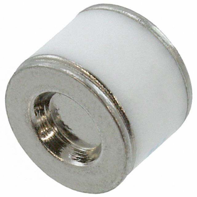
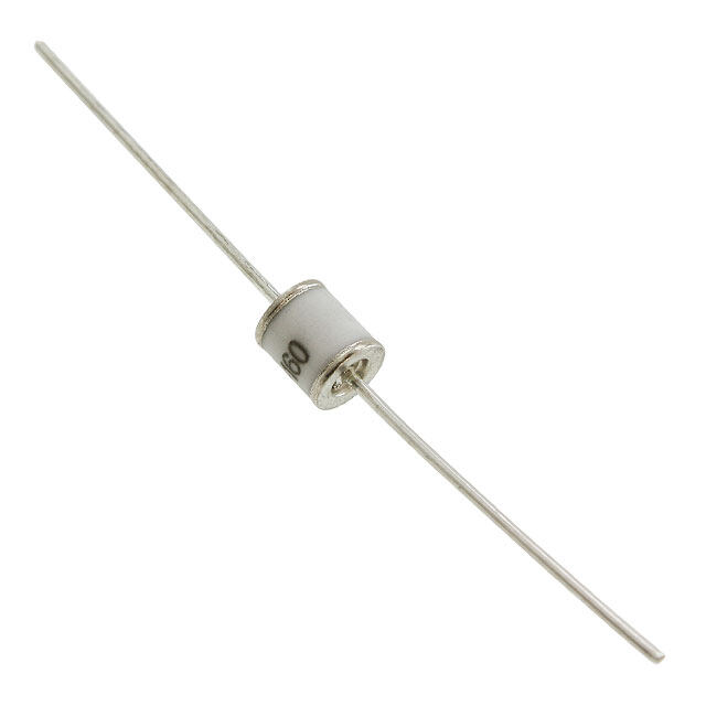
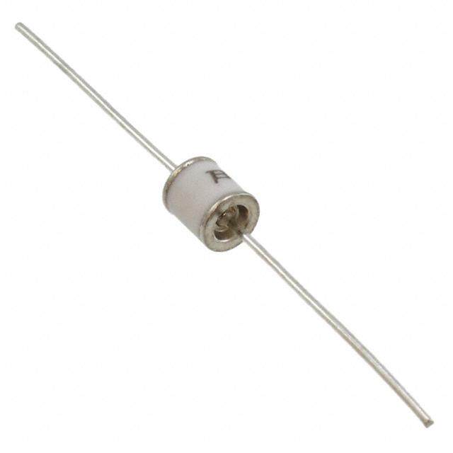
ICGOO电子元器件商城为您提供B88069X4760T902由EPCOS设计生产,在icgoo商城现货销售,并且可以通过原厂、代理商等渠道进行代购。 B88069X4760T902价格参考¥18.77-¥28.44。EPCOSB88069X4760T902封装/规格:气体放电管避雷器(GDT), Gas Discharge Tube 90V 5000A (5kA) ±20% 2 Pole Surface Mount。您可以下载B88069X4760T902参考资料、Datasheet数据手册功能说明书,资料中有B88069X4760T902 详细功能的应用电路图电压和使用方法及教程。
B88069X4760T902是EPCOS(现为TDK集团)生产的一款气体放电管避雷器(GDT),主要用于过电压保护。该器件具备高冲击电流承受能力,典型直流击穿电压约为760V,适用于通信设备、电信线路、网络接口及工业控制系统等需要防雷和瞬态过压保护的场合。

典型应用场景包括:电话线路、DSL宽带接入、有线电视(CATV)系统、基站天馈线系统、安防监控系统以及电源信号隔离保护电路。其高绝缘电阻和低电容特性确保了在正常工作状态下对信号传输影响极小,同时能在遭遇雷击或电网瞬态过压时迅速导通,将高压脉冲泄放到地,保护后级敏感电子元件。

此外,该GDT常与其他保护器件(如TVS二极管、压敏电阻)配合组成多级防护电路,提升整体可靠性。由于其密封陶瓷结构,具有良好的稳定性和长寿命,适合在恶劣环境和户外设备中使用。广泛应用于通信基础设施、智能电网、轨道交通和楼宇安防等领域,提供高效、可靠的初级过压保护。
| 参数 | 数值 |
| 产品目录 | |
| 描述 | M51-C90XSMD气体放电管 - GDT /气体等离子体避雷器 90V 5KA 2 Electrode |
| 产品分类 | 气体放电管避雷器 (GDT)气体放电管 - GDT /气体等离子体避雷器 |
| 品牌 | EPCOS |
| 产品手册 | |
| 产品图片 | |
| rohs | 符合RoHS无铅 / 符合限制有害物质指令(RoHS)规范要求 |
| 产品系列 | EPCOS B88069X4760T902- |
| mouser_ship_limit | 该产品可能需要其他文件才能进口到中国。 |
| 数据手册 | |
| 产品型号 | B88069X4760T902 |
| 产品种类 | 气体放电管 - GDT /气体等离子体避雷器 |
| 其它名称 | 495-5919-6 |
| 包装 | Digi-Reel® |
| 商标 | EPCOS |
| 安装类型 | 表面贴装 |
| 容差 | ±20% |
| 封装 | Reel |
| 封装/外壳 | 轴向圆柱形,径向SMT弯曲 |
| 尺寸 | 5.3 mm D x 9.3 mm L |
| 峰值脉冲电流 | 5 kA |
| 工厂包装数量 | 900 |
| 技术 | 2-Electrode Arrester |
| 故障短接 | 无 |
| 极数 | 2 |
| 标准包装 | 1 |
| 电压-DC火花放电(标称值) | 90V |
| 电压额定值 | 90 V |
| 电极数量 | 2 |
| 电流-AC放电(标称值) | 5A |
| 直流击穿电压(标称) | 90 V |
| 端接类型 | SMD/SMT |
| 脉冲放电电流(8/20us) | 5.0kA |


- 商务部:美国ITC正式对集成电路等产品启动337调查
- 曝三星4nm工艺存在良率问题 高通将骁龙8 Gen1或转产台积电
- 太阳诱电将投资9.5亿元在常州建新厂生产MLCC 预计2023年完工
- 英特尔发布欧洲新工厂建设计划 深化IDM 2.0 战略
- 台积电先进制程称霸业界 有大客户加持明年业绩稳了
- 达到5530亿美元!SIA预计今年全球半导体销售额将创下新高
- 英特尔拟将自动驾驶子公司Mobileye上市 估值或超500亿美元
- 三星加码芯片和SET,合并消费电子和移动部门,撤换高东真等 CEO
- 三星电子宣布重大人事变动 还合并消费电子和移动部门
- 海关总署:前11个月进口集成电路产品价值2.52万亿元 增长14.8%


PDF Datasheet 数据手册内容提取
Surge arrester 2-electrode arrester Series/Type: M51-C90XSMD Ordering code: B88069X4760T902 Date: 2015-07-30 Version: 06 Content of header bars 1 and 2 of data sheet will be automatically entered in headers and footers! Please fill in the table and then change the color to "white". This ensures that the table disappears (invisible) for the customer PDF. Don't change formatting when entering or pasting text in the table and don't add any cell or line in and to it! Identification/Classification 1 Surge arrester (header 1 + top left bar): Identification/Classification 2 2-electrode arrester (header 2 + bottom left header bar): Ordering code: (top right header bar) B88069X4760T902 Series/Type: (bottom right header bar) M51-C90XSMD Preliminary data (optional): Department: PPD AB PD / PPD AB PM Date: 2015-07-30 Version: 06 EPCOS AG 2015. Reproduction, publication and dissemination of this publication, enclosures hereto and the information contained therein without EPCOS' prior express consent is prohibited. EPCOS AG is a TDK Group Company.
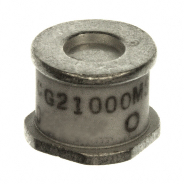
Surge arrester B88069X4760T902 2-electrode arrester M51-C90XSMD Features Applications Small size Modem High current rating XDSL-splitter Very fast response time Data lines Stable performance over life Tuner Very low capacitance Antenna High insulation resistance Excellent SMD handling RoHS-compatible Electrical specifications DC spark-over voltage 1) 2) 90 V Tolerance 20 % Min. 72 V Max. 108 V Impulse spark-over voltage at 100 V/µs - for 99% of measured values < 450 V - typical values of distribution < 350 V at 1 kV/µs - for 99% of measured values < 600 V - typical values of distribution < 550 V Service life 10 operations 50 Hz, 1 s 5 A 1 operation 50 Hz, 0.18 s (9 cycles) 10 A 10 operations 8/20 µs 5 kA 1 operation 8/20 µs 10 kA 1 operation 10/350 µs 1 kA Insulation resistance at 50 V > 1 G DC Capacitance at 1 MHz < 1 pF Arc voltage at 1 A ~ 15 V Glow to arc transition current ~ 0.8 A Glow voltage ~ 60 V Weight ~ 1 g Operation and storage temperature 40 ... +90 °C Climatic category (IEC 60068-1) 40/090/21 Marking blue negative 90 YY O 90 - Nominal voltage YY - Year of production O - Non radioactive Certification UL 497B (E163070) 1) At delivery AQL 0.65 level II, DIN ISO 2859 2) In ionized mode Terms in accordance with ITU-T Rec. K.12, IEC 61663-2 and IEC 61643-311 PPD AB PD / PPD AB PM 2015-07-30 Please read Cautions and warnings and Page 2 of 5 Important notes at the end of this document.
Surge arrester B88069X4760T902 2-electrode arrester M51-C90XSMD Dimensional drawing in mm Ordering code and packing advice B88069X4760T902 = 900 pcs. on SMD-tape PPD AB PD / PPD AB PM 2015-07-30 Please read Cautions and warnings and Page 3 of 5 Important notes at the end of this document.
Surge arrester B88069X4760T902 2-electrode arrester M51-C90XSMD Soldering parameter Reflow soldering Reflow profile Sn- Pb eutectic Pb-free features assembly assembly Preheat and soak - Temperature min T 100 °C 150 °C smin - Temperature max T 150 °C 200 °C smax - Time t to t 60 ... 120 s 60 ... 180 s smin smax Average ramp-up T to T max. 3 °C/ s max. 3 °C/ s rate smax p Liquidous temperature T 183 °C 217 °C L Time at liquidous t 60 ... 150 s 60 ... 150 s L Peak package body temperature *, T, T 220 ... 235 °C ** 245 ... 260 °C ** Classification p C temperature ** Time (t) ** within p 5 °C of the specified 20 s *** 30 s *** classification temperature (T ) C Average ramp-down T to T max. 6 °C/ s max. 6 °C/ s rate p smax Time 25 °C to peak max. 6 min max. 8 min temperature * = Tolerance for peak profile temperature (Tp) is defined as a supplier minimum and a user maximum. ** = For details please refer to JEDEC J-STD-020D. *** = Tolerance for time at peak profile temperature (tp) is defined as a supplier minimum and a user maximum. Cautions and warnings Do not operate surge arresters in power supply networks, whose maximum operating voltage exceeds the minimum spark-over voltage of the surge arresters. Surge arresters may become hot in the event of longer periods of current stress (burn risk). In the event of overload the connectors may fail or the component may be destroyed. Surge arresters must be handled with care and must not be dropped. Do not continue to use damaged surge arresters. The shown SMD pad dimensions represent a safe way to mount the arrester and are a recommendation of the manufacturer. During the reflow process it must be assured that no solder material reduces the insulation distance between the pads below the arrester. SMD surge arresters should be soldered within 24 month after shipment. Display of ordering codes for EPCOS products The ordering code for one and the same EPCOS product can be represented differently in data sheets, data books, other publications, on the EPCOS website, or in order-related documents such as shipping notes, order confirmations and product labels. The varying representations of the ordering codes are due to different processes employed and do not affect the specifications of the respective products. Detailed information can be found on the Internet under www.epcos.com/orderingcodes PPD AB PD / PPD AB PM 2015-07-30 Please read Cautions and warnings and Page 4 of 5 Important notes at the end of this document.
Important notes The following applies to all products named in this publication: 1. Some parts of this publication contain statements about the suitability of our products for certain areas of application. These statements are based on our knowledge of typical requirements that are often placed on our products in the areas of application concerned. We nevertheless expressly point out that such statements cannot be regarded as binding statements about the suitability of our products for a particular customer application. As a rule we are either unfamiliar with individual customer applications or less familiar with them than the customers themselves. For these reasons, it is always ultimately incumbent on the customer to check and decide whether a product with the properties described in the product specification is suitable for use in a particular customer application. 2. We also point out that in individual cases, a malfunction of electronic components or failure before the end of their usual service life cannot be completely ruled out in the current state of the art, even if they are operated as specified. In customer applications requiring a very high level of operational safety and especially in customer applications in which the malfunction or failure of an electronic component could endanger human life or health (e.g. in accident prevention or life-saving systems), it must therefore be ensured by means of suitable design of the customer application or other action taken by the customer (e.g. installation of protective circuitry or redundancy) that no injury or damage is sustained by third parties in the event of malfunction or failure of an electronic component. 3. The warnings, cautions and product-specific notes must be observed. 4. In order to satisfy certain technical requirements, some of the products described in this publication may contain substances subject to restrictions in certain jurisdictions (e.g. because they are classed as hazardous). Useful information on this will be found in our Material Data Sheets on the Internet (www.tdk-electronics.tdk.com/material). Should you have any more detailed questions, please contact our sales offices. 5. We constantly strive to improve our products. Consequently, the products described in this publication may change from time to time. The same is true of the corresponding product specifications. Please check therefore to what extent product descriptions and specifications contained in this publication are still applicable before or when you place an order. We also reserve the right to discontinue production and delivery of products. Consequently, we cannot guarantee that all products named in this publication will always be available. The aforementioned does not apply in the case of individual agreements deviating from the foregoing for customer-specific products. 6. Unless otherwise agreed in individual contracts, all orders are subject to our General Terms and Conditions of Supply. 7. Our manufacturing sites serving the automotive business apply the IATF 16949 standard. The IATF certifications confirm our compliance with requirements regarding the quality management system in the automotive industry. Referring to customer requirements and customer specific requirements (“CSR”) TDK always has and will continue to have the policy of respecting individual agreements. Even if IATF 16949 may appear to support the acceptance of unilateral requirements, we hereby like to emphasize that only requirements mutually agreed upon can and will be implemented in our Quality Management System. For clarification purposes we like to point out that obligations from IATF 16949 shall only become legally binding if individually agreed upon. 8. The trade names EPCOS, CeraCharge, CeraDiode, CeraLink, CeraPad, CeraPlas, CSMP, CTVS, DeltaCap, DigiSiMic, ExoCore, FilterCap, FormFit, LeaXield, MiniBlue, MiniCell, MKD, MKK, MotorCap, PCC, PhaseCap, PhaseCube, PhaseMod, PhiCap, PowerHap, PQSine, PQvar, SIFERRIT, SIFI, SIKOREL, SilverCap, SIMDAD, SiMic, SIMID, SineFormer, SIOV, ThermoFuse, WindCap are trademarks registered or pending in Europe and in other countries. Further information will be found on the Internet at www.tdk- electronics.tdk.com/trademarks. Release 2018-10 Page 5 of 5