ICGOO在线商城 > 电感器,线圈,扼流圈 > 固定值电感器 > B82477R4334M100
 Datasheet下载
- 型号: B82477R4334M100
- 制造商: EPCOS
- 库位|库存: xxxx|xxxx
- 要求:
| 数量阶梯 | 香港交货 | 国内含税 |
| +xxxx | $xxxx | ¥xxxx |
查看当月历史价格
查看今年历史价格
B82477R4334M100产品简介:
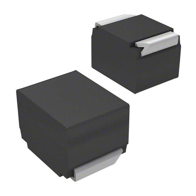
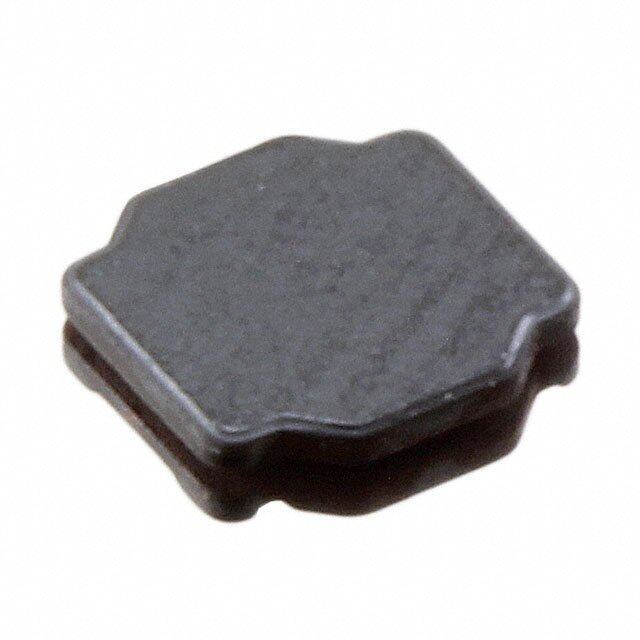
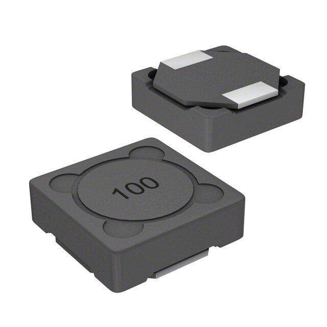
ICGOO电子元器件商城为您提供B82477R4334M100由EPCOS设计生产,在icgoo商城现货销售,并且可以通过原厂、代理商等渠道进行代购。 B82477R4334M100价格参考。EPCOSB82477R4334M100封装/规格:固定值电感器, 330µH Shielded Wirewound Inductor 1.18A 425mOhm Max Nonstandard 。您可以下载B82477R4334M100参考资料、Datasheet数据手册功能说明书,资料中有B82477R4334M100 详细功能的应用电路图电压和使用方法及教程。
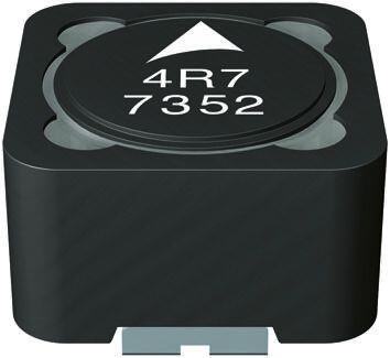
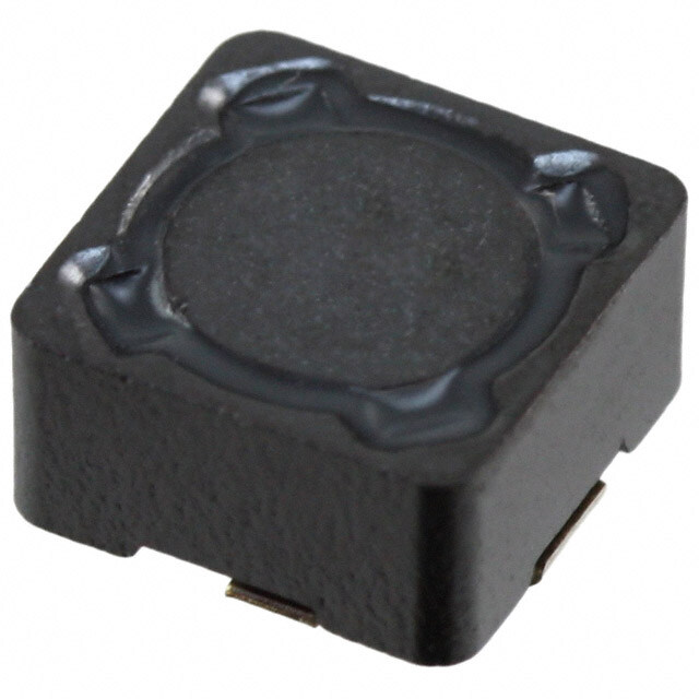
EPCOS(现为TDK集团成员)的固定值电感器型号B82477R4334M100,是一款表面贴装功率电感器,广泛应用于各类电子设备中。该电感器具有330μH的电感值、较高的饱和电流和低直流电阻,适用于需要稳定电能转换和滤波的电源电路。

其主要应用场景包括:开关模式电源(SMPS),如DC-DC转换器,用于消费类电子产品(如智能手机、平板电脑、路由器等)中的电压调节;工业控制设备中的电源模块;以及电信设备和嵌入式系统中的电源管理单元。此外,该器件具备良好的温度稳定性和抗干扰能力,适合在要求高可靠性的环境中使用。

由于采用屏蔽结构,B82477R4334M100电磁干扰(EMI)较低,有助于满足电磁兼容性(EMC)要求,因此也常用于对噪声敏感的应用中。其表面贴装设计便于自动化生产,提升组装效率,适用于大批量制造场景。

综上所述,B82477R4334M100是一款性能可靠的功率电感器,特别适用于中小型功率的高效电源系统中,是现代电子设备中实现稳定供电的关键元件之一。
| 参数 | 数值 |
| 产品目录 | |
| DC电阻(DCR) | 425 毫欧最大 |
| 描述 | INDUCTOR POWER 330UH 1.12A SMD |
| 产品分类 | |
| 品牌 | EPCOS Inc |
| 数据手册 | |
| 产品图片 |
|
| 产品型号 | B82477R4334M100 |
| rohs | 无铅 / 符合限制有害物质指令(RoHS)规范要求 |
| 产品系列 | B82477R4 |
| 不同频率时的Q值 | - |
| 供应商器件封装 | - |
| 其它名称 | 495-4543-6 |
| 包装 | Digi-Reel® |
| 大小/尺寸 | 0.492" 长 x 0.492" 宽(12.50mm x 12.50mm) |
| 安装类型 | 表面贴装 |
| 容差 | ±20% |
| 封装/外壳 | 非标准 |
| 屏蔽 | 屏蔽 |
| 工作温度 | - |
| 材料-磁芯 | 铁氧体 |
| 标准包装 | 1 |
| 特色产品 | http://www.digikey.cn/product-highlights/cn/zh/epcos-b82477r-series-smt-inductors/1945 |
| 电感 | 330µH |
| 电流-饱和值 | 1.8A |
| 类型 | 绕线 |
| 频率-测试 | 100kHz |
| 频率-自谐振 | - |
| 额定电流 | 1.12A |
| 高度-安装(最大值) | 0.335"(8.50mm) |


- 商务部:美国ITC正式对集成电路等产品启动337调查
- 曝三星4nm工艺存在良率问题 高通将骁龙8 Gen1或转产台积电
- 太阳诱电将投资9.5亿元在常州建新厂生产MLCC 预计2023年完工
- 英特尔发布欧洲新工厂建设计划 深化IDM 2.0 战略
- 台积电先进制程称霸业界 有大客户加持明年业绩稳了
- 达到5530亿美元!SIA预计今年全球半导体销售额将创下新高
- 英特尔拟将自动驾驶子公司Mobileye上市 估值或超500亿美元
- 三星加码芯片和SET,合并消费电子和移动部门,撤换高东真等 CEO
- 三星电子宣布重大人事变动 还合并消费电子和移动部门
- 海关总署:前11个月进口集成电路产品价值2.52万亿元 增长14.8%


PDF Datasheet 数据手册内容提取
SMT power inductors Size 12.5 x 12.5 x 8.5 mm Series/Type: B82477R4 Ordering code: Date: April 2015 Version: Content of header bars 1 and 2 of data sheet will be automaticallyentered in headers and footers! Please fill in the table and then change the color to "white". This ensures that the table disappears (invisible) for the customer PDF. Don't change formatting when entering or pasting text in the table and don't add any cell or line in and to it! Identification/Classification 1 SMT power inductors (header 1 + top left bar): Identification/Classification 2 Size 12.5 x 12.5 x 8.5 mm (header 2 + bottom left header bar): Ordering code: (top right header bar) Series/Type: (bottom right header bar) B82477R4 Preliminary data (optional): (if necessary) MAG IN PD EPCOS AG 2015. Reproduction, publication and dissemination of this publication, enclosures hereto and the information contained therein without EPCOS' prior express consent is prohibited. EPCOS AG is a TDK Group Company.
SMT power inductors Size 12.5 x 12.5 x 8.5 mm B82477R4 Rated inductance 0.82 ...1000 µH Construction ■ Ferrite core ■ Magnetically shielded ■ Winding: enamel copper wire ■ Winding soldered to terminals ■ Injection moulded base Features ■ High mechanical stability ■ Temperature range up to +150 °C ■ High rated current ■ Increased current handling capability compared to B82477P4 series (I +30%) sat ■ Qualified to AEC-Q200 ■ Suitable for lead-free reflow soldering as referenced in JEDEC J-STD 020D ■ RoHS-compatible ■ Halogen Free in the meaning of Cl ≤ 900ppm, Br ≤ 900pm, Cl+Br ≤ 1500 ppm Applications ■ Filtering of supply voltages ■ Coupling, decoupling ■ DC/DC converters ■ Automotive electronics Terminals ■ Base material Cu (L ≤ 10 µH), CuSn6P (L > 15 µH) ■ Layer composition Ni, Sn (lead-free) ■ Electro-plated Marking ■ Marking on component: Manufacturer, L value (µH, coded), manufacturing date (YWWD) ■ Minimum data on reel: Manufacturer, ordering code, L value, quantity, date of packing Delivery mode and packing unit ■ 24-mm blister tape, wound on 330-mm reel ■ Packing unit: 350 pcs./reel MAG IN PD April 2015 Please read Cautions and warnings and Page 2 of 8 Important notes at the end of this document.
SMT power inductors Size 12.5 x 12.5 x 8.5 mm B82477R4 Dimensional drawing and layout recommendation Dimensions in mm Taping and packing Blister tape Dimensions in mm MAG IN PD April 2015 Please read Cautions and warnings and Page 3 of 8 Important notes at the end of this document.
SMT power inductors Size 12.5 x 12.5 x 8.5 mm B82477R4 Technical data and measuring conditions Measured with LCR meter Agilent 4284A at frequency f , 0.1 V. Rated inductance L L R +20°C Operating temperature range –55 °C ... +150 °C Max. permissible DC with temperature increase of ≤ 40 K Rated current I R measured at +20 °C Max. permissible DC current with inductance decrease ∆L/L of Saturation current I 0 Sat approx. 10% DC resistance R Measured at +20 °C Dip and look method Sn95.5Ag3.8Cu0.7: +(245 ±5) °C, (5 ±0.3) s Solderability (lead-free) Wetting of soldering area ≥ 90% (based on IEC 60068-2-58) Resistance to soldering heat +260 °C, 40 s (as referenced in JEDEC J-STD 020D) Climatic category 55/150/56 (to IEC 60068-1) Mounted: –55 °C … +150 °C Storage conditions Packaged: –25 °C … +40 °C, ≤ 75% RH Weight Approx. 4 g MAG IN PD April 2015 Please read Cautions and warnings and Page 4 of 8 Important notes at the end of this document.
SMT power inductors Size 12.5 x 12.5 x 8.5 mm B82477R4 Characteristics and ordering codes L Tolerance f I I I R R Ordering code R L R sat, min sat, typ max typ µH MHz A A A mΩ mΩ 0.82 12.25 27.0 38.0 5.5 3.8 B82477R4821M100 1.50 10.25 20.0 27.0 6.5 4.8 B82477R4152M100 2.00 20% = M 0.1 9.50 18.0 24.0 8.0 5.9 B82477R4202M100 3.00 8.70 15.5 18.0 9.0 6.8 B82477R4302M100 3.60 8.50 13.0 16.0 10.0 7.9 B82477R4362M100 4.70 7.85 12.2 14.25 11.0 8.9 B82477R4472M100 5.60 7.60 11.0 12.75 11.5 9.9 B82477R4562M100 6.80 6.95 10.5 12.0 15.0 11.0 B82477R4682M100 10 6.20 8.75 10.25 18.5 16.4 B82477R4103M100 15 5.00 7.25 8.75 25.0 22.8 B82477R4153M100 22 4.45 6.10 7.25 32.0 28.1 B82477R4223M100 33 3.55 5.20 6.00 50.0 46.3 B82477R4333M100 47 3.35 4.30 4.90 60.0 55.7 B82477R4473M100 68 2.80 3.55 3.90 85.0 80.1 B82477R4683M100 100 2.35 2.90 3.25 120 112 B82477R4104M100 150 1.90 2.40 2.80 175 158 B82477R4154M100 220 1.45 2.00 2.20 290 275 B82477R4224M100 330 1.18 1.70 1.80 425 405 B82477R4334M100 470 1.07 1.35 1.50 605 578 B82477R4474M100 680 0.88 1.10 1.25 860 830 B82477R4684M100 1000 0.72 0.95 1.05 1350 1250 B82477R4105M100 Current derating I /I versus ambient temperature T op R A MAG IN PD April 2015 Please read Cautions and warnings and Page 5 of 8 Important notes at the end of this document.
SMT power inductors Size 12.5 x 12.5 x 8.5 mm B82477R4 Typical curves: Inductance vs. DC superposition measured with LCR meter Agilent 4284A at T = +20 °C a 820nH 3µH 1.2 5.0 1.0 H 4.0 µ 0.8 L/ 3.0 H L / µ0.6 2.0 0.4 1.0 0.2 0.0 0.0 0 2000 4000 6000 8000 100001200014000160001800020000 0 5000 10000 15000 20000 25000 30000 35000 40000 Idc [mA] Idc [mA] 10µH 33µH 15.0 50 12.5 40 L/µH 10.0 L/µH 30 7.5 20 5.0 2.5 10 0.0 0 0 2000 4000 6000 8000 10000 12000 14000 0 1000 2000 3000 4000 5000 6000 7000 8000 9000 10000 Idc [mA] Idc [mA] 100µH 330µH 150 500 125 400 H 100 L/µ 300 H µ 75 L/ 200 50 25 100 0 0 0 500 1000 1500 2000 2500 3000 3500 4000 4500 5000 0 500 1000 1500 2000 2500 3000 Idc [mA] Idc [mA] 1000µH 1500 1250 H L/µ 1000 750 500 250 0 0 200 400 600 800 1000 1200 1400 1600 Idc [mA] MAG IN PD April 2015 Please read Cautions and warnings and Page 6 of 8 Important notes at the end of this document.
SMT power inductors Size 12.5 x 12.5 x 8.5 mm B82477R4 Cautions and warnings ■ Please note the recommendations in our Inductors data book (latest edition) and in the data sheets. – Particular attention should be paid to the derating curves given there. – The soldering conditions should also be observed. Temperatures quoted in relation to wave soldering refer to the pin, not the housing. ■ If the components are to be washed varnished it is necessary to check whether the washing varnish agent that is used has a negative effect on the wire insulation, any plastics that are used, or on glued joints. In particular, it is possible for washing varnish agent residues to have a negative effect in the long-term on wire insulation. Washing processes may damage the product due to the possible static or cyclic mechanical loads (e.g. ultrasonic cleaning). They may cause cracks to develop on the product and its parts, which might lead to reduced reliability or lifetime. ■ The following points must be observed if the components are potted in customer applications: – Many potting materials shrink as they harden. They therefore exert a pressure on the plastic housing or core. This pressure can have a deleterious effect on electrical properties, and in extreme cases can damage the core or plastic housing mechanically. – It is necessary to check whether the potting material used attacks or destroys the wire insulation, plastics or glue. – The effect of the potting material can change the high-frequecy behaviour of the components. ■ Ferrites are sensitive to direct impact. This can cause the core material to flake, or lead to breakage of the core. ■ Even for customer-specific products, conclusive validation of the component in the circuit can only be carried out by the customer. Display of ordering codes for EPCOS products The ordering code for one and the same EPCOS product can be represented differently in data sheets, data books, other publications, on the EPCOS website, or in order-related documents such as shipping notes, order confirmations and product labels. The varying representations of the ordering codes are due to different processes employed and do not affect the specifications of the respective products. Detailed information can be found on the Internet under www.epcos.com/orderingcodes MAG IN PD April 2015 Please read Cautions and warnings and Page 7 of 8 Important notes at the end of this document.
Important notes The following applies to all products named in this publication: 1. Some parts of this publication contain statements about the suitability of our products for certain areas of application. These statements are based on our knowledge of typical requirements that are often placed on our products in the areas of application concerned. We nevertheless expressly point out that such statements cannot be regarded as binding statements about the suitability of our products for a particular customer application. As a rule, EPCOS is either unfamiliar with individual customer applications or less familiar with them than the customers themselves. For these reasons, it is always ultimately incumbent on the customer to check and decide whether an EPCOS product with the properties described in the product specification is suitable for use in a particular customer application. 2. We also point out that in individual cases, a malfunction of electronic components or failure before the end of their usual service life cannot be completely ruled out in the current state of the art, even if they are operated as specified. In customer applications requiring a very high level of operational safety and especially in customer applications in which the malfunction or failure of an electronic component could endanger human life or health (e.g. in accident prevention or life-saving systems), it must therefore be ensured by means of suitable design of the customer application or other action taken by the customer (e.g. installation of protective circuitry or redundancy) that no injury or damage is sustained by third parties in the event of malfunction or failure of an electronic component. 3. The warnings, cautions and product-specific notes must be observed. 4. In order to satisfy certain technical requirements, some of the products described in this publication may contain substances subject to restrictions in certain jurisdictions (e.g. because they are classed as hazardous). Useful information on this will be found in our Material Data Sheets on the Internet (www.epcos.com/material). Should you have any more detailed questions, please contact our sales offices. 5. We constantly strive to improve our products. Consequently, the products described in this publication may change from time to time. The same is true of the corresponding product specifications. Please check therefore to what extent product descriptions and specifications contained in this publication are still applicable before or when you place an order. We also reserve the right to discontinue production and delivery of products. Consequently, we cannot guarantee that all products named in this publication will always be available. The aforementioned does not apply in the case of individual agreements deviating from the foregoing for customer-specific products. 6. Unless otherwise agreed in individual contracts, all orders are subject to the current version of the “General Terms of Delivery for Products and Services in the Electrical Industry” published by the German Electrical and Electronics Industry Association (ZVEI). 7. The trade names EPCOS, Alu-X, CeraDiode, CeraLink, CeraPad, CeraPlas, CSMP, CSSP, CTVS, DeltaCap, DigiSiMic, DSSP, ExoCore, FilterCap, FormFit, LeaXield, MiniBlue, MiniCell, MKD, MKK, MotorCap, PCC, PhaseCap, PhaseCube, PhaseMod, PhiCap, PQSine, SIFERRIT, SIFI, SIKOREL, SilverCap, SIMDAD, SiMic, SIMID, SineFormer, SIOV, SIP5D, SIP5K, TFAP, ThermoFuse, WindCap are trademarks registered or pending in Europe and in other countries. Further information will be found on the Internet at www.epcos.com/trademarks. Page 8 of 8
Mouser Electronics Authorized Distributor Click to View Pricing, Inventory, Delivery & Lifecycle Information: E PCOS / TDK: B82477R4103M100 B82477R4104M100 B82477R4474M100 B82477R4821M100 B82477R4105M100 B82477R4682M100 B82477R4154M100 B82477R4362M100 B82477R4333M100 B82477R4334M100 B82477R4202M100 B82477R4473M100 B82477R4684M100 B82477R4223M100 B82477R4562M100 B82477R4472M100 B82477R4683M100 B82477R4224M100 B82477R4152M100 B82477R4302M100 B82477R4153M100