ICGOO在线商城 > B72590D50H160
.jpg)
 Datasheet下载
- 型号: B72590D50H160
- 制造商: EPCOS
- 库位|库存: xxxx|xxxx
- 要求:
| 数量阶梯 | 香港交货 | 国内含税 |
| +xxxx | $xxxx | ¥xxxx |
查看当月历史价格
查看今年历史价格
B72590D50H160产品简介:
ICGOO电子元器件商城为您提供B72590D50H160由EPCOS设计生产,在icgoo商城现货销售,并且可以通过原厂、代理商等渠道进行代购。 提供B72590D50H160价格参考以及EPCOSB72590D50H160封装/规格参数等产品信息。 你可以下载B72590D50H160参考资料、Datasheet数据手册功能说明书, 资料中有B72590D50H160详细功能的应用电路图电压和使用方法及教程。
| 参数 | 数值 |
| 产品目录 | |
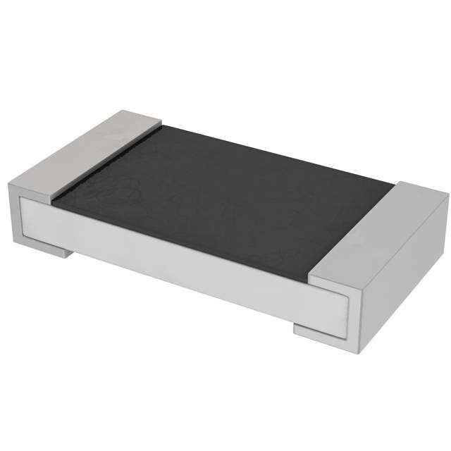
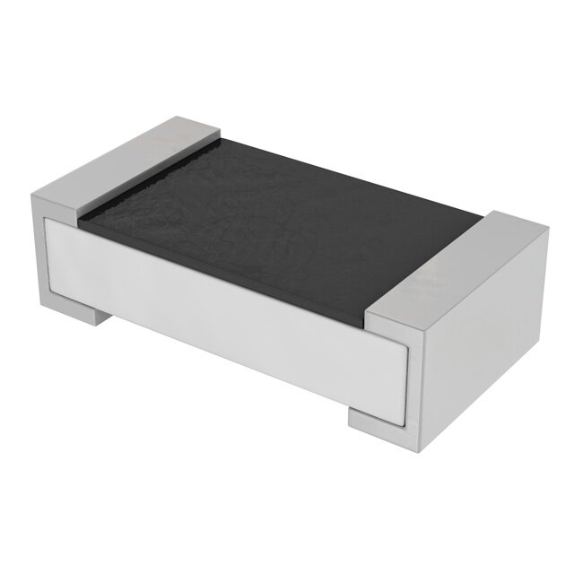
| 描述 | VARISTOR 150V 0402ESD 抑制器 Var CDS2C05HDMI1 |
| 产品分类 | |
| 品牌 | EPCOS Inc |
| 产品手册 | |
| 产品图片 |
|
| rohs | 符合RoHS无铅 / 符合限制有害物质指令(RoHS)规范要求 |
| 产品系列 | EPCOS B72590D50H160- |
| 数据手册 | |
| 产品型号 | B72590D50H160 |
| 产品培训模块 | http://www.digikey.cn/PTM/IndividualPTM.page?site=cn&lang=zhs&ptm=15733http://www.digikey.cn/PTM/IndividualPTM.page?site=cn&lang=zhs&ptm=26133 |
| 产品目录绘图 |
|
| 产品目录页面 | |
| 产品种类 | ESD 抑制器 |
| 其它名称 | 495-3684-1 |
| 击穿电压 | 150 V |
| 包装 | 剪切带 (CT) |
| 变阻器电压 | 150V |
| 商标 | EPCOS |
| 封装 | Reel |
| 封装/外壳 | 0402(1005 公制) |
| 封装/箱体 | 0402 (1005 metric) |
| 工作温度范围 | - 40 C to + 85 C |
| 工作电压 | 5.6 V |
| 工厂包装数量 | 10000 |
| 最大AC电压 | - |
| 最大DC电压 | 5.6VDC |
| 标准包装 | 1 |
| 电容 | 0.6 pF |
| 电流-浪涌 | - |
| 电路数 | 1 |
| 端接类型 | SMD/SMT |
| 系列 | CeraDiodes High-Speed |
| 能量 | - |
| 通道 | 1 Channel |
| 零件号别名 | B72590D0050H160 CDS2C05HDMI1 |


- 商务部:美国ITC正式对集成电路等产品启动337调查
- 曝三星4nm工艺存在良率问题 高通将骁龙8 Gen1或转产台积电
- 太阳诱电将投资9.5亿元在常州建新厂生产MLCC 预计2023年完工
- 英特尔发布欧洲新工厂建设计划 深化IDM 2.0 战略
- 台积电先进制程称霸业界 有大客户加持明年业绩稳了
- 达到5530亿美元!SIA预计今年全球半导体销售额将创下新高
- 英特尔拟将自动驾驶子公司Mobileye上市 估值或超500亿美元
- 三星加码芯片和SET,合并消费电子和移动部门,撤换高东真等 CEO
- 三星电子宣布重大人事变动 还合并消费电子和移动部门
- 海关总署:前11个月进口集成电路产品价值2.52万亿元 增长14.8%


PDF Datasheet 数据手册内容提取
CeraDiodes High-speed series Series/Type: Date: April2016 ©EPCOSAG2016.Reproduction,publicationanddisseminationofthispublication,enclosuresheretoandthe informationcontainedthereinwithoutEPCOS'priorexpressconsentisprohibited. EPCOSAGisaTDKGroupCompany.
CeraDiodes High-speedseries EPCOStypedesignation CD S 2 C05 GTA CD(cid:4)CeraDiode Device S(cid:4)Singledevice A(cid:4)Arraydevice Casesizesofsingledevices Code Casesize (inch/mm) 1 0201/0603 2 0402/1005 3 0603/1608 4 1003/2508 Casesizesofarraydevices Code Casesize (inch/mm) 3 0506/1216 4 0508/1220 5 0612/1632 6 1012/2532 Ratedvoltage Code VDC 040 4 050 5.5/5.6 090 9 120 12 150 15 160 16 180 18 200 20/22 300 30 360 36 480 48 700 70 900 90 201 200 Type GTA(cid:4)Standard GTB(cid:4)LED GTH(cid:4)High-speed HDMI1(cid:4)Capacitancevalue<1pF HDMI2(cid:4)Capacitancevalue<1pF PleasereadCautionsandwarningsand Page2of25 Importantnotesattheendofthisdocument.
CeraDiodes High-speedseries Orderingcodesystem B72590 D 0050 A0 60 Type,casesizesanddevice Chipsize Device Orderingcode (inch/mm) 0201/0603 Single B72440... 0402/1005 Single B72590... 0603/1608 Single B72500... 1003/2508 Single B72570... 0506/1216 Array B72755... 0508/1220 Array B72714... 0612/1632 Array B72724... 1012/2532 Array B72735... D(cid:4)CeraDiode Ratedvoltage Code VDC 0040 4 0050 5.5/5.6 0090 9 0120 12 0150 15 0160 16 0180 18 0200 20/22 0300 30 0360 36 0480 48 0700 70 0900 90 0201 200 Type A0(cid:4)Standard B0(cid:4)LED H0(cid:4)High-speed H1(cid:4)Capacitancevalue<1pF H2(cid:4)Capacitancevalue<1pF Packaging 60(cid:4)Cardboardtape,180-mmreel 62(cid:4)Blistertape,180-mmreel 70(cid:4)Cardboardtape,330-mmreel 72(cid:4)Blistertape,330-mmreel PleasereadCautionsandwarningsand Page3of25 Importantnotesattheendofthisdocument.
CeraDiodes High-speedseries Features Singlechip Verylowcapacitancevalues0.6upto10pF ESDprotectiontoIEC61000-4-2,level4 BidirectionalESDprotectioninonecomponent NochangeinESDprotectionperformanceattemperatures upto85(cid:176) C(temperaturederating) 4-foldarray Lowparasiticinductance Lowleakagecurrent Fastresponsetime<0.5ns Lead-freenickelbarrierterminationssuitableforlead-freesoldering RoHS-compatible 2/4data+1supply Applications Interfaces,datalines(USB,IEEE1394,Ethernet,parallelport, SATA,DisplayPort,etc.),audiolines(digital)andvideolines (analog),DVI,HDMI,ICsandI/Oports Consumerelectronicproducts(TV,DVDplayer/recorder,set-top box,gameconsoles,MP3player,digitalstill/videocamera,etc.) EDPproducts(desktopandnotebookcomputer,monitor,PDA, printer,memorycard,controlunit,headset,speaker,HDD,optical drive,etc.) Industrialapplications Mobilephoneapplications Design Multilayertechnology Nickelbarriertermination(Ag/Ni/Sn)forlead-freesoldering Marking Duetothesymmetricalconfigurationnomarkinginformationis needed. Generaltechnicaldata MaximumDCoperatingvoltage V 5.5...30 V DC,max Typicalcapacitance C 0.6...10 pF typ AirdischargeESDcapability toIEC61000-4-2 V 15 kV ESD,air ContactdischargeESDcapability toIEC61000-4-2 V 8 kV ESD,contact Leakagecurrent (V =5.6V) I 1 m A leak leak Operatingtemperature Top (cid:5)40/+85 (cid:176) C Storagetemperature LCT/UCT (cid:5)40/+125 (cid:176) C PleasereadCautionsandwarningsand Page4of25 Importantnotesattheendofthisdocument.
CeraDiodes High-speedseries Electricalspecificationsandorderingcodes Maximumratings(T =85(cid:176) C)andcharacteristics(T =25(cid:176) C) op,max A Type Orderingcode VDC,max VBR,min Vclamp,max Ctyp Cmax (1mA) (1A) (1MHz,1V) (1MHz,1V) V V V pF pF Array,2/4data+1supply,0506,SOT-666 CDA3C05GTH B72755D0050H062 5.6 106 395 2.2 3.5 Array,2/4data+1supply,1012,SOT-236L CDA6C05GTH B72735D0050H062 5.6 52 195 7 10 Array,4-fold,0508,nosemiconductordiodeequivalent CDA4C16GTH B72714D0160H060 16 22 66 10 15 Array,4-fold,0612,nosemiconductordiodeequivalent CDA5C16GTH B72724D0160H062 16 80 350 3 5 Single,0201,nosemiconductordiodeequivalent CDS1C05GTH1 B72440C0050H160 5.5 17 33 7 - CDS1C05GTH2 B72440C0050H260 5.5 20 66 3 - Single,0402,SOD-723 CDS2C05HDMI1 B72590D0050H160 5.6 150 - 0.6 0.9 CDS2C05HDMI2 B72590D0050H260 5.6 90 - 0.6 0.9 CDS2C12GTH B72590D0120H060 12 20 66 4.5 - CDS2C15GTH B72590D0150H060 15 23 66 10 15 CDS2C16GTH B72590D0160H060 16 65 290 2 3 CDS2C20GTH B72590D0200H060 20 30 80 10 13 Single,0603,SOD-523 CDS3C05HDMI1 B72500D0050H160 5.6 150 - 0.6 0.9 CDS3C16GTH B72500D0160H060 16 65 290 3 5 CDS3C30GTH B72500D0300H060 30 50 120 10 15 Single,1003,SOD-323 CDS4C16GTH B72570D0160H060 16 38 146 3 5 Typicalcharacteristics PleasereadCautionsandwarningsand Page5of25 Importantnotesattheendofthisdocument.
CeraDiodes High-speedseries Dimensionaldrawings Singledevice Dimensionsinmm Case (inch) 0201 0402 0603 1003 size (mm) 0603 1005 1608 2508 Min. Max. Min. Max. Min. Max. Min. Max. l 0.57 0.63 0.85 1.15 1.45 1.75 2.34 2.74 w 0.27 0.33 0.4 0.6 0.7 0.9 0.7 0.9 h 0.27 0.33 0.4 0.6 0.7 0.9 0.7 0.9 k 0.1 0.2 0.1 0.3 0.1 0.4 0.13 0.75 Arraydevices 4-foldarray 2/4data+1supply Dimensioninmm Casesize (inch) 0506 0508 0612 1012 (mm) 1216 1220 1632 2532 Min. Max. Min. Max. Min. Max. Min. Max. l 1.50 1.70 1.8 2.2 3.0 3.4 2.90 3.50 w 1.20 1.40 1.05 1.45 1.45 1.75 2.25 2.75 h - 0.6 - 0.9 - 0.9 - 1.2 d 0.2 0.4 0.2 0.4 0.25 0.55 0.35 0.65 e 0.4 0.6 0.4 0.6 0.61 0.91 0.8 1.1 k - 0.35 - 0.35 - 0.35 - 0.45 PleasereadCautionsandwarningsand Page6of25 Importantnotesattheendofthisdocument.
CeraDiodes High-speedseries Recommendedsolderpads Singledevice Dimensionsinmm Casesize (inch) 0201 0402 0603 1003 (mm) 0603 1005 1608 2508 A 0.3 0.6 1.0 0.8 B 0.25 0.6 1.0 0.8 C 0.3 0.5 1.0 1.45 Arraydevices 4-foldarray 2/4data+1supply Dimensionsinmm Casesize (inch) 0506 0508 0612 1012 (mm) 1216 1220 1632 2532 A 0.36 0.35 0.5 0.7 B 0.84 0.9 0.7 1.0 C 0.62 0.4 1.2 1.4 E 0.50 0.5 0.76 0.95 PleasereadCautionsandwarningsand Page7of25 Importantnotesattheendofthisdocument.
CeraDiodes High-speedseries Pinconfigurations Singledevice Pin Description P1 GND P2 I/Oline Arraydevices 4-foldarray Pin Description P1 GND P2 GND P3 GND P4 GND P5 I/Oline1 P6 I/Oline2 P7 I/Oline3 P8 I/Oline4 2/4data+1supply Pin Description P1 I/Oline1 P2 GND P3 I/Oline2 P4 I/Oline3 P5 V DC P6 I/Oline4 PleasereadCautionsandwarningsand Page8of25 Importantnotesattheendofthisdocument.
CeraDiodes High-speedseries Termination Singledevice Arraydevice PleasereadCautionsandwarningsand Page9of25 Importantnotesattheendofthisdocument.
CeraDiodes High-speedseries Deliverymode EIAcasesize Taping Reelsize Packingunit Type Orderingcode mm pcs. 0201 Cardboard 180 15000 CDS1C05GTH1 B72440C0050H160 0201 Cardboard 180 15000 CDS1C05GTH2 B72440C0050H260 0402 Cardboard 180 10000 CDS2C05HDMI1 B72590D0050H160 0402 Cardboard 180 10000 CDS2C05HDMI2 B72590D0050H260 0402 Cardboard 180 10000 CDS2C12GTH B72590D0120H060 0402 Cardboard 180 10000 CDS2C15GTH B72590D0150H060 0402 Cardboard 180 10000 CDS2C16GTH B72590D0160H060 0402 Cardboard 180 10000 CDS2C20GTH B72590D0200H060 0506 Blister 180 3000 CDA3C05GTH B72755D0050H062 0508 Cardboard 180 4000 CDA4C16GTH B72714D0160H060 0603 Cardboard 180 4000 CDS3C05HDMI1 B72500D0050H160 0603 Cardboard 180 4000 CDS3C16GTH B72500D0160H060 0603 Cardboard 180 4000 CDS3C30GTH B72500D0300H060 0612 Blister 180 3000 CDA5C16GTH B72724D0160H062 1003 Cardboard 180 4000 CDS4C16GTH B72570D0160H060 1012 Blister 180 2000 CDA6C05GTH B72735D0050H062 PleasereadCautionsandwarningsand Page10of25 Importantnotesattheendofthisdocument.
CeraDiodes High-speedseries 1 TapingandpackingforchipandarrayCeraDiodes 1.1 Cardboardtape(tapingtoIEC60286-3) Dimensionsinmm Casesize(inch) 0201 0402 0603 1003 0508 Tolerance (mm) 0603 1005 1608 2508 1220 Compartmentwidth A 0.38– 0.05 0.6 0.95 1.0 1.6 – 0.2 0 Compartmentlength B 0.68– 0.05 1.15 1.8 2.85 2.4 – 0.2 0 Sprocketholediameter D0 1.5– 0.1 1.5 1.5 1.5 1.5 +0.1/(cid:5)0 Sprocketholepitch P 4.0– 0.11) 4.0 4.0 4.0 4.0 – 0.11) 0 Distancecenterholetocenter P 2.0– 0.05 2.0 2.0 2.0 2.0 – 0.05 2 compartment Pitchofcomponentcompartments P 2.0– 0.05 2.0 4.0 4.0 4.0 – 0.1 1 Tapewidth W 8.0– 0.3 8.0 8.0 8.0 8.0 – 0.3 Distanceedgetocenterofhole E 1.75– 0.1 1.75 1.75 1.75 1.75 – 0.1 Distancecenterholetocenter F 3.5– 0.05 3.5 3.5 3.5 3.5 – 0.05 compartment Distancecompartmenttoedge G 0.75min. 0.75 0.75 0.75 0.75 min. Thicknesstape T 0.42– 0.02 0.6 0.9 0.95 0.95 max. Overallthickness T 0.4min. 0.7 1.1 1.1 1.10 max. 2 1)£– 0.2mmover10sprocketholes PleasereadCautionsandwarningsand Page11of25 Importantnotesattheendofthisdocument.
CeraDiodes High-speedseries 1.2 Blistertape(tapingtoIEC60286-3) Dimensionsinmm Casesize(inch) 0506 0612 1012 Tolerance (mm) 1216 1632 2532 Compartmentwidth A 1.5 1.8 2.8 – 0.2 0 Compartmentlength B 1.8 3.4 3.5 – 0.2 0 Compartmentheight K 0.8 1.8 1.8 max. 0 Sprocketholediameter D0 1.5 1.5 1.5 +0.1/(cid:5)0 Compartmentholediameter D 0.3 0.3 0.3 min. 1 Sprocketholepitch P 4.0 4.0 4.0 – 0.11) 0 Distancecenterholetocenter P 2.0 2.0 2.0 – 0.05 2 compartment Pitchofcomponentcompartments P 4.0 4.0 4.0 – 0.1 1 Tapewidth W 8.0 8.0 8.0 – 0.3 Distanceedgetocenterofhole E 1.75 1.75 1.75 – 0.1 Distancecenterholetocenter F 3.5 3.5 3.5 – 0.05 compartment Distancecompartmenttoedge G 0.75 0.75 0.75 min. Thicknesstape T 0.3 0.3 0.3 max. Overallthickness T 1.3 2.5 2.5 max. 2 1)£– 0.2mmover10sprocketholes PleasereadCautionsandwarningsand Page12of25 Importantnotesattheendofthisdocument.
CeraDiodes High-speedseries 1.3 Reelpacking Dimensionsinmm Dimensions Tolerance Dimensions Tolerance Reeldiameter A 180 +0/–3 330 +0/–2 Reelwidth(inside) W 8.4 +1.5/–0 8.4 +1.5/–0 1 Reelwidth(outside) W 14.4 max. 14.4 max. 2 Package:8-mmtape Reelmaterial:Plastic 1.4 Packingunits Casesize ˘ 180-mmreel ˘ 330-mmreel Tape (inch)/(mm) pieces pieces 0201/0603 15000 - cardboard 0402/1005 10000 50000 cardboard 0603/1608 4000 16000 cardboard 1003/2508 4000 16000 cardboard 0506/1216 3000 12000 blister 0508/1220 4000 16000 cardboard 0612/1632 3000 12000 blister 1012/2532 2000 8000 blister PleasereadCautionsandwarningsand Page13of25 Importantnotesattheendofthisdocument.
CeraDiodes High-speedseries Solderingdirections 1 Reflowsolderingtemperatureprofile Recommendedtemperaturecharacteristicforreflowsolderingfollowing JEDECJ-STD-020D Profilefeature Sn-Pbeutecticassembly Pb-freeassembly Preheatandsoak -Temperaturemin T 100(cid:176) C 150(cid:176) C smin -Temperaturemax T 150(cid:176) C 200(cid:176) C smax -Time t tot 60...120s 60...180s smin smax Averageramp-uprate T toT 3(cid:176) C/smax. 3(cid:176) C/smax. smax p Liquidoustemperature T 183(cid:176) C 217(cid:176) C L Timeatliquidous t 60...150s 60...150s L Peakpackagebodytemperature T1) 220(cid:176) C...235(cid:176) C2) 245(cid:176) C...260(cid:176) C2) p Time(t )3)within5(cid:176) Cofspecified P 20s3) 30s3) classificationtemperature(T) c Averageramp-downrate T toT 6(cid:176) C/smax. 6(cid:176) C/smax. p smax Time25(cid:176) Ctopeaktemperature maximum6min maximum8min 1) Toleranceforpeakprofiletemperature(TP)isdefinedasasupplierminimumandausermaximum. 2) Dependingonpackagethickness.FordetailspleaserefertoJEDECJ-STD-020D. 3) Tolerancefortimeatpeakprofiletemperature(tP)isdefinedasasupplierminimumandausermaximum. Note:Alltemperaturesrefertotopsideofthepackage,measuredonthepackagebodysurface. Numberofreflowcycles:3 PleasereadCautionsandwarningsand Page14of25 Importantnotesattheendofthisdocument.
CeraDiodes High-speedseries 2 Solderingguidelines Theuseofmild,non-activatedfluxesforsolderingisrecommended,aswellaspropercleaningof thePCB. ThecomponentsaresuitableforreflowsolderingtoJEDECJ-STD-020D. 3 Solderjointprofiles/solderquantity 3.1 Cementquantity Thecomponentisfixedontothecircuitboardwithcementpriortosoldering.Itmuststillbeable tomoveslightly.Whentheboardisplacedintothereflowoven,excessivelyrigidfixingcanlead to high forces acting on the component and thus to a break. In addition, too much cement can leadtounsymmetricalstressingandthustomechanicalfractureofthecomponent.Thecement mustalsobesosoftduringmountingthatnomechanicalstressingoccurs. 3.2 Mountingthecomponentsontheboard Itisbesttomountthecomponentsontheboardbeforesolderingsothatoneterminationdoesnot entertheovenfirstandthesecondterminationissolderedsubsequently.Theidealcaseissimul- taneouswettingofbothterminations. 3.3 Solderjointprofiles Ifthemeniscusheightistoolow,thatmeansthesolderquantityistoolow,thesolderjointmay break,i.e.thecomponentbecomesdetachedfromthejoint.Thisproblemissometimesinterpret- edasleachingoftheexternalterminations. Ifthesoldermeniscusistoohigh,i.e.thesolderquantityistoolarge,theviseeffectmayoccur. As the solder cools down, the solder contracts in the direction of the component. If there is too muchsolderonthecomponent,ithasnoleewaytoevadethestressandmaybreak,asinavise. PleasereadCautionsandwarningsand Page15of25 Importantnotesattheendofthisdocument.
CeraDiodes High-speedseries 3.3.1 Solderjointprofilesfornickelbarriertermination Goodandpoorsolderjointscausedbyamountofsolderininfraredreflowsoldering PleasereadCautionsandwarningsand Page16of25 Importantnotesattheendofthisdocument.
CeraDiodes High-speedseries 4 Solderabilitytests Test Standard Testconditions/ Testconditions/ Criteria/testresults Sn-Pbsoldering Pb-freesoldering Wettability IEC Immersionin Immersionin Coveringof95% 60068-2-58 60/40SnPbsolder Sn96.5Ag3.0Cu0.5 ofendtermination, usingnon-activated solderusingnon-or checkedbyvisual fluxat215– 3(cid:176) Cfor lowactivatedflux inspection 3– 0.3s at245– 5(cid:176) C for3– 0.3s Leaching IEC Immersionin Immersionin Noleachingof resistance 60068-2-58 60/40SnPb Sn96.5Ag3.0Cu0.5 contacts solderusing solderusingnon-or mildlyactivatedflux lowactivatedflux withoutpreheating withoutpreheating at 255– 5(cid:176) C at 255– 5(cid:176) C for10– 1s for10– 1s Testsof IEC Immersionin Immersionin Capacitancechange: resistanceto 60068-2-58 60/40SnPbfor10s Sn96.5Ag3.0Cu0.5 (cid:5)15%£D C£ 15% solderingheat at260(cid:176) C for10sat260(cid:176) C forSMDs Note: Leachingofthetermination Effectiveareaattheterminationmightbelostifthesolderingtemperatureand/orimmersiontime arenotkeptwithintherecommendedconditions.Leachingoftheouterelectrodeshouldnotex- ceed 25% of the chip end area (full length of the edge A-B-C-D) and 25% of the length A-B, shownbelowasmountedonthesubstrate. Assinglechip Asmountedonsubstrate PleasereadCautionsandwarningsand Page17of25 Importantnotesattheendofthisdocument.
CeraDiodes High-speedseries 5 Notesforpropersoldering 5.1 Preheatingandcooling Theaverageramp-upratemustnotexceed3(cid:176) C/s. Thecoolingratemustnotexceed8(cid:176) C/s. 5.2 Repair/rework Manual soldering with a soldering iron must be avoided, hot-air methods are recommended for makingrepairs. 5.3 Cleaning All environmentally compatible agents are suitable for cleaning. Select the appropriate cleaning solutionaccordingtothetypeoffluxused.Thetemperaturedifferencebetweenthecomponents and cleaning liquid must not be greater than 100 (cid:176) C. Ultrasonic cleaning should be carried out withtheutmostcaution.Toohighultrasonicpowercanimpairtheadhesivestrengthofthemetal- lizedsurfaces.InsufficientorexcessivecleaningcanbedetrimentaltoCeraDiodeperformance. 5.4 Solderpasteprinting(reflowsoldering) An excessive application of solder paste results in too high a solder fillet, thus making the chip moresusceptibletomechanicalandthermalstress.Thiswillleadtotheformationofcracks.Too little solder paste reduces the adhesive strength on the outer electrodes and thus weakens the bonding to the PCB. The solder should be applied smoothly to the end surface to a height of min.0.2mm. 5.5 Selectionofflux Usedfluxshouldhavelessthanorequalto0.1wt%ofhalogenatedcontent,sincefluxresidue aftersolderingcouldleadtocorrosionoftheterminationand/orincreasedleakagecurrentonthe surfaceoftheCeraDiode.Strongacidicfluxmustnotbeused.Theamountoffluxappliedshould becarefullycontrolled,sinceanexcessmaygeneratefluxgas,whichinturnisdetrimentaltosol- derability. 5.6 Storage Solderability is guaranteed for one year from date of delivery, provided that components are storedintheiroriginalpackages. Storagetemperature: (cid:5)25(cid:176) Cto+45(cid:176) C Relativehumidity: £ 75%annualaverage,£ 95%on30daysayear ThesolderabilityoftheexternalelectrodesmaydeteriorateifSMDsarestoredwheretheyareex- posed to high humidity, dust or harmful gas (hydrogen chloride, sulfurous acid gas or hydrogen sulfide). DonotstoreSMDswheretheyareexposedtoheatordirectsunlight.Otherwisethepackingma- terialmaybedeformedorSMDsmaysticktogether,causingproblemsduringmounting. Afteropeningthefactoryseals,suchaspolyvinyl-sealedpackages,itisrecommendedtousethe SMDsassoonaspossible. PleasereadCautionsandwarningsand Page18of25 Importantnotesattheendofthisdocument.
CeraDiodes High-speedseries 5.7 Placementofcomponentsoncircuitboard Itisofadvantagetoplacethecomponentsontheboardbeforesolderingsothattheirtwotermi- nalsdonotenterthesolderovenatdifferenttimes.Ideally,bothterminalsshouldbewettedsi- multaneously. 5.8 Solderingcaution Suddenheatingorcoolingofthecomponentresultsinthermaldestructionbycracks. Anexcessivelylongsolderingtimeorhighsolderingtemperatureresultsinleachingoftheout- erelectrodes,causingpooradhesionduetolossofcontactbetweenelectrodesandtermina- tion. Avoidmanualsolderingwithasolderingiron. WavesolderingmustnotbeappliedforCeraDiodesdesignatedforreflowsolderingonly. Keeptotherecommendeddown-coolingrate. 5.9 Standards CECC00802 IEC60068-2-58 IEC60068-2-20 JEDECJ-STD-020D PleasereadCautionsandwarningsand Page19of25 Importantnotesattheendofthisdocument.
CeraDiodes High-speedseries Symbolsandterms CeraDiode Semiconductordiode C Maximumcapacitance max C Typicalcapacitance typ I I ,I (Reverse)current@breakdownvoltage BR R T I I (Reverse)leakagecurrent leak RM I I ,I Current@clampingvoltage,peakpulse PP P PP current P P Peakpulsepower PP PP T Operatingtemperature op T Storagetemperature stg V V (Reverse)breakdownvoltage BR BR V Minimumbreakdownvoltage BR,min V V V Clampingvoltage clamp cl, C V Maximumclampingvoltage clamp,max V V ,V ,V ,V (Reverse)stand-offvoltage,working DC RM RWM WM DC voltage,operatingvoltage V MaximumDCoperatingvoltage DC,max V AirdischargeESDcapability ESD,air V ContactdischargeESDcapability ESD,contact V V ,V ,V ,V (Reverse)voltage@leakagecurrent leak RM RWM WM DC -*) I Current@forwardvoltage F -*) I ,I @V (Reverse)current@maximumreverse RM RM,max RM stand-offvoltage,workingvoltage, operatingvoltage -*) V Forwardvoltage F *)NotapplicableduetobidirectionalcharacteristicsofCeraDiodes PleasereadCautionsandwarningsand Page20of25 Importantnotesattheendofthisdocument.
CeraDiodes High-speedseries Cautionsandwarnings General SomepartsofthispublicationcontainstatementsaboutthesuitabilityofourCeraDiodesforcer- tainareasofapplication,includingrecommendationsaboutincorporation/design-inoftheseprod- ucts into customer applications. The statements are based on our knowledge of typical require- mentsoftenmadeofourCeraDiodesintheparticularareas.Weneverthelessexpresslypointout that such statements cannot be regarded as binding statements about the suitability of our CeraDiodesforaparticularcustomerapplication.Asarule,EPCOSiseitherunfamiliarwithindi- vidualcustomerapplicationsorlessfamiliarwiththemthanthecustomersthemselves.Forthese reasons, it is always incumbent on the customer to check and decide whether the CeraDiodes withthepropertiesdescribedintheproductspecificationaresuitableforuseinaparticularcus- tomerapplication. Do not use EPCOS CeraDiodes for purposes not identified in our specifications, application notesanddatabooks. EnsurethesuitabilityofaCeraDiodeinparticularbytestingitforreliabilityduringdesign-in.Al- waysevaluateaCeraDiodeunderworst-caseconditions. PayspecialattentiontothereliabilityofCeraDiodesintendedforuseinsafety-criticalapplica- tions(e.g.medicalequipment,automotive,spacecraft,nuclearpowerplant). Designnotes AlwaysconnectaCeraDiodeinparallelwiththeelectroniccircuittobeprotected. Consider maximum rated power dissipation if a CeraDiode has insufficient time to cool down betweenanumberofpulsesoccurringwithinaspecifiedisolatedtimeperiod.Ensurethatelec- tricalcharacteristicsdonotdegrade. Considerderatingathigheroperatingtemperatures.Choosethehighestvoltageclasscompati- blewithderatingathighertemperatures. Surge currents beyond specified values will puncture a CeraDiode. In extreme cases a CeraDiodewillburst. Ifsteepsurgecurrentedgesaretobeexpected,makesureyourdesignisaslow-inductance aspossible. Insomecasesthemalfunctioningofpassiveelectroniccomponentsorfailurebeforetheendof theirservicelifecannotbecompletelyruledoutinthecurrentstateoftheart,eveniftheyare operatedasspecified.DonotuseCeraDiodesinapplicationsrequiringaveryhighlevelofop- erationalsafetyandespeciallywhenthemalfunctionorfailureofapassiveelectroniccompo- nent could endanger human life or health (e.g. in accident prevention, life-saving systems, or automotivebatterylineapplicationssuchasclamp30),ensurebysuitabledesignoftheappli- cationorothermeasures(e.g.installationofprotectivecircuitryorredundancy)thatnoinjuryor damageissustainedbythirdpartiesintheeventofsuchamalfunctionorfailure. Specified values only apply to CeraDiodes that have not been subject to prior electrical, me- chanicalorthermaldamage.TheuseofCeraDiodesinline-to-groundapplicationsistherefore notadvisable,anditisonlyallowedtogetherwithsafetycountermeasureslikethermalfuses. PleasereadCautionsandwarningsand Page21of25 Importantnotesattheendofthisdocument.
CeraDiodes High-speedseries Storage OnlystoreCeraDiodesintheiroriginalpackaging.Donotopenthepackagebeforestorage. Storageconditionsinoriginalpackaging:temperature-25to+45(cid:176) C,relativehumidity£ 75%an- nualaverage,maximum95%,dewprecipitationisinadmissible. Do not store CeraDiodes where they are exposed to heat or direct sunlight. Otherwise the packagingmaterialmaybedeformedorCeraDiodesmaysticktogether,causingproblemsdur- ingmounting. AvoidcontaminationoftheCeraDiodesurfaceduringstorage,handlingandprocessing. AvoidstoringCeraDiodesinharmfulenvironmentswheretheyareexposedtocorrosivegases forexample(SO,Cl). x UseCeraDiodesassoonaspossibleafteropeningfactorysealssuchaspolyvinyl-sealedpack- ages. SolderCeraDiodesaftershipmentfromEPCOSwithinthetimespecified:12months. Handling DonotdropCeraDiodesandallowthemtobechipped. DonottouchCeraDiodeswithyourbarehands-glovesarerecommended. AvoidcontaminationoftheCeraDiodesurfaceduringhandling. Washing processes may damage the product due to the possible static or cyclic mechanical loads(e.g.ultrasoniccleaning).Theymaycausecrackstodevelopontheproductanditsparts, whichmightleadtoreducedreliabilityorlifetime. Mounting WhenCeraDiodesareencapsulatedwithsealingmaterialorovermoldedwithplasticmaterial, beawarethatpotting,sealingoradhesivecompoundscanproducechemicalreactionsinthe CeraDiodeceramicthatwilldegradeitselectricalcharacteristicsandreduceitslifetime. Makesureanelectrodeisnotscratchedbefore,duringorafterthemountingprocess. MakesurecontactsandhousingsusedforassemblywithCeraDiodesarecleanbeforemount- ing. ThesurfacetemperatureofanoperatingCeraDiodecanbehigher.Ensurethatadjacentcom- ponentsareplacedatasufficientdistancefromaCeraDiodetoallowpropercooling. AvoidcontaminationoftheCeraDiodesurfaceduringprocessing. OnlyCeraDiodeswithanNibarrierterminationareapprovedforlead-freesoldering. Soldering Completeremovaloffluxisrecommendedtoavoidsurfacecontaminationthatcanresultinan instableand/orhighleakagecurrent. Useresin-typeornon-activatedflux. Bearinmindthatinsufficientpreheatingmaycauseceramiccracks. Rapidcoolingbydippinginsolventisnotrecommended,otherwiseacomponentmaycrack. PleasereadCautionsandwarningsand Page22of25 Importantnotesattheendofthisdocument.
CeraDiodes High-speedseries Operation UseCeraDiodesonlywithinthespecifiedoperatingtemperaturerange. UseCeraDiodesonlywithinspecifiedvoltageandcurrentranges. Environmental conditions must not harm a CeraDiode. Only use them in normal atmospheric conditions.Reducingtheatmosphere(e.g.hydrogenornitrogenatmosphere)isprohibited. Prevent a CeraDiode from contacting liquids and solvents. Make sure that no water enters a CeraDiode(e.g.throughplugterminals). Avoiddewingandcondensation. EPCOSCeraDiodesaredesignedforencasedapplications.Underallcircumstancesavoidex- posureto: (cid:5)directsunlight (cid:5)rainorcondensation (cid:5)steam,salinespray (cid:5)corrosivegases (cid:5)atmospherewithreducedoxygencontent EPCOS CeraDiodes are not suitable for switching applications or voltage stabilization where staticpowerdissipationisrequired. Thislistingdoesnotclaimtobecomplete,itmerelyreflectstheexperienceofEPCOSAG. DisplayoforderingcodesforEPCOSproducts TheorderingcodeforoneandthesameEPCOSproductcanberepresenteddifferentlyindata sheets,databooks,otherpublications,ontheEPCOSwebsite,orinorder-relateddocuments suchasshippingnotes,orderconfirmationsandproductlabels.Thevaryingrepresentationsof theorderingcodesareduetodifferentprocessesemployedanddonotaffectthe specificationsoftherespectiveproducts.DetailedinformationcanbefoundontheInternet underwww.epcos.com/orderingcodes PleasereadCautionsandwarningsand Page23of25 Importantnotesattheendofthisdocument.
Importantnotes The following applies toall products named in this publication: 1. Some parts of this publication contain statements about the suitability of our products for certain areas of application. These statements are based on our knowledge of typical requirements that are often placed on our products in the areas of application concerned. We nevertheless expressly point out that such statements cannot be regarded as binding statements about the suitability of our products for a particular customer application. As a rule we are either unfamiliar with individual customer applications or less familiar with them than the customers themselves. For these reasons, it is always ultimately incumbent on the customer to check and decide whether a product with the properties described in the product specification is suitable for use in a particular customer application. 2. We also point out that in individual cases, a malfunction of electronic components or failure before the end of their usual service life cannot be completely ruled out in the current state of the art, even if they are operated as specified. In customer applications requiring a very high level of operational safety and especially in customer applications in which the malfunction or failure of an electronic component could endanger human life or health (e.g. in accident prevention or life-saving systems), it must therefore be ensured by means of suitable design of the customer application or other action taken by the customer (e.g. installation of protective circuitry or redundancy) that no injury or damage is sustained by third parties in the event of malfunction or failure of an electronic component. 3. The warnings, cautions and product-specific notes must be observed. 4. In order to satisfy certain technical requirements, some of the products described in this publication may contain substances subject to restrictions in certain jurisdictions (e.g. because they are classed as hazardous). Useful information on this will be found in our Material Data Sheets on the Internet (www.tdk-electronics.tdk.com/material). Should you have any more detailed questions, please contact our sales offices. 5. We constantly strive to improve our products. Consequently, the products described in this publication may change from time to time. The same is true of the corresponding product specifications. Please check therefore to what extent product descriptions and specifications contained in this publication are still applicable before or when you place an order. We also reserve the right to discontinue production and delivery of products. Consequently, we cannot guarantee that all products named in this publication will always be available. The aforementioned does not apply in the case of individual agreements deviating from the foregoing for customer-specific products. 6. Unless otherwise agreed in individual contracts, all orders are subject to our General Terms and Conditions of Supply. 7. Our manufacturing sites serving the automotive business apply the IATF 16949 standard. The IATF certifications confirm our compliance with requirements regarding the quality management system in the automotive industry. Referring to customer requirements and customer specific requirements (“CSR”) TDK always has and will continue to have the policy of respecting individual agreements. Even if IATF 16949 may appear to support the acceptance of unilateral requirements, we hereby like to emphasize that only requirements mutually agreed upon can and will be implemented in our Quality Management System. For clarification purposes we like to point out that obligations from IATF 16949 shall only become legally binding if individually agreed upon. Page24of25
Importantnotes 8. The trade names EPCOS, CeraCharge, CeraDiode, CeraLink, CeraPad, CeraPlas, CSMP, CTVS, DeltaCap, DigiSiMic, ExoCore, FilterCap, FormFit, LeaXield, MiniBlue, MiniCell, MKD, MKK, MotorCap, PCC, PhaseCap, PhaseCube, PhaseMod, PhiCap, PowerHap, PQSine, PQvar, SIFERRIT, SIFI, SIKOREL, SilverCap, SIMDAD, SiMic, SIMID, SineFormer, SIOV, ThermoFuse, WindCap are trademarks registered or pending in Europe and in other countries. Further information will be found on the Internet at www.tdk-electronics.tdk.com/trademarks. Release 2018-10 Page25of25
Mouser Electronics Authorized Distributor Click to View Pricing, Inventory, Delivery & Lifecycle Information: E PCOS / TDK: B72590D150H60 B72590D50H160 B72500D160H60 B72500D300H60 B72570D160H60 B72590D160H60 B72714D160H60 B72724D160H62 B72735D50H62 B72440C50H260 B72590D200H60 B72590D50H260 B72440C50H160 B72590D120H60 B72500D50H160 B72755D50H62 B72590D0360A060