ICGOO在线商城 > 电路保护 > TVS - 变阻器,MOV > B72500E8250L060

 Datasheet下载
- 型号: B72500E8250L060
- 制造商: EPCOS
- 库位|库存: xxxx|xxxx
- 要求:
| 数量阶梯 | 香港交货 | 国内含税 |
| +xxxx | $xxxx | ¥xxxx |
查看当月历史价格
查看今年历史价格
B72500E8250L060产品简介:
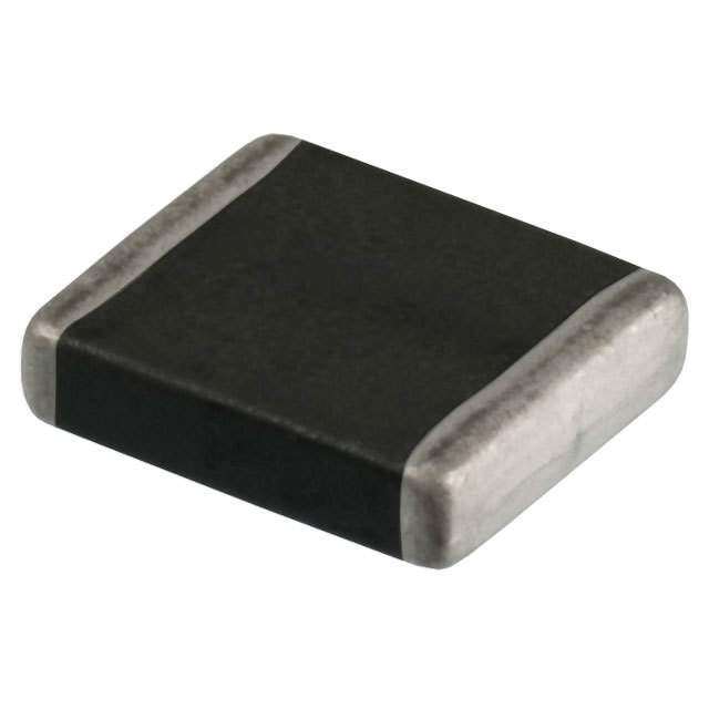
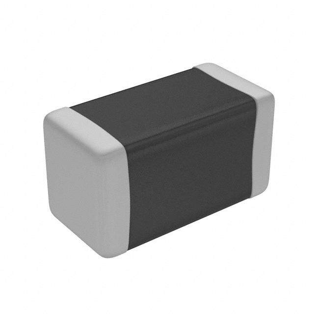
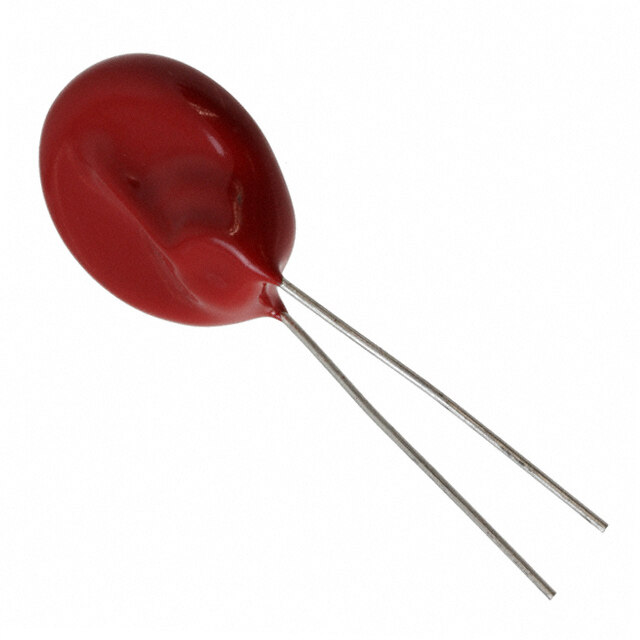
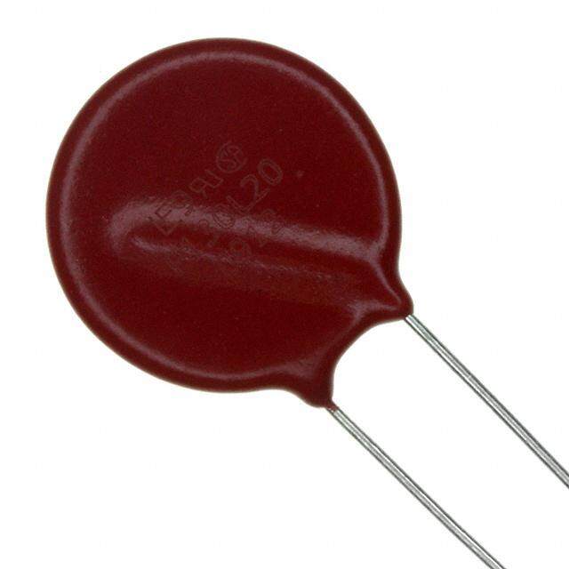
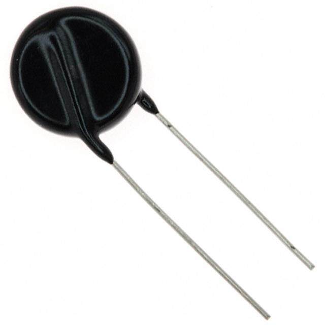
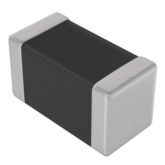
ICGOO电子元器件商城为您提供B72500E8250L060由EPCOS设计生产,在icgoo商城现货销售,并且可以通过原厂、代理商等渠道进行代购。 B72500E8250L060价格参考。EPCOSB72500E8250L060封装/规格:TVS - 变阻器,MOV, 61V 5A Varistor 1 Circuit 表面贴装,MLCV 0603(1608 公制)。您可以下载B72500E8250L060参考资料、Datasheet数据手册功能说明书,资料中有B72500E8250L060 详细功能的应用电路图电压和使用方法及教程。
B72500E8250L060 是 EPCOS(隶属于 TDK)生产的一款金属氧化物压敏电阻(MOV),属于瞬态电压抑制(TVS)器件的一种。其主要功能是用于吸收电路中因雷击、静电放电或开关操作引起的瞬态过电压,从而保护电子设备免受损坏。

该型号的压敏电阻广泛应用于以下场景:

1. 电源系统保护:用于交流或直流电源输入端,防止电网中瞬态电压对后级电路造成损害,常见于电源适配器、UPS、变频器等设备中。

2. 工业控制系统:在PLC、变频器、伺服驱动器等工业设备中,用于保护控制电路免受外部电压浪涌干扰。

3. 通信设备:应用于通信基站、路由器、交换机等设备中,保护信号线路和电源线路免受雷击或静电影响。

4. 家电产品:如空调、洗衣机、冰箱等家电中,用于保护电机、控制板等关键部件。

5. 新能源领域:如太阳能逆变器、风能控制系统等,用于恶劣环境下的电压浪涌防护。

该器件具有响应速度快、通流能力大、可靠性高等特点,适合需要高稳定性和高性能保护的电子系统。
| 参数 | 数值 |
| 产品目录 | |
| 描述 | VARISTOR 51.9V 5A 0603压敏电阻 25Vrms 5A CT0603L25HSG |
| 产品分类 | |
| 品牌 | EPCOS |
| 产品手册 | |
| 产品图片 |
|
| rohs | 符合RoHS无铅 / 符合限制有害物质指令(RoHS)规范要求 |
| 产品系列 | EPCOS B72500E8250L060- |
| 数据手册 | |
| 产品型号 | B72500E8250L060 |
| 产品 | MLV |
| 产品种类 | 压敏电阻 |
| 其它名称 | 495-4605-2 |
| 包装 | 带卷 (TR) |
| 变阻器电压 | 51.9 V |
| 商标 | EPCOS |
| 外壳代码-in | 0603 |
| 外壳代码-mm | 1608 |
| 外壳宽度 | 0.8 mm |
| 安装 | SMD/SMT |
| 容差 | 35 % |
| 封装 | Reel |
| 封装/外壳 | 0603(1608 公制) |
| 封装/箱体 | 0603 (1608 metric) |
| 尺寸 | 0.8 mm W x 1.6 mm L |
| 峰值浪涌电流 | 5 A |
| 工作温度范围 | - 55 C to + 125 C |
| 工厂包装数量 | 3000 |
| 最大AC电压 | 25VAC |
| 最大DC电压 | 32VDC |
| 标准包装 | 4,000 |
| 浪涌能量额定值 | 50 mJ |
| 特色产品 | http://www.digikey.com/product-highlights/cn/zh/epcos-b725-e-series/2913 |
| 电压额定值AC | 25 V |
| 电压额定值DC | 32 V |
| 电容 | 10 pF |
| 电流-浪涌 | 5A |
| 电路数 | 1 |
| 端接类型 | SMD/SMT |
| 系列 | E |
| 能量 | 0.05J |
| 钳位电压 | 120 V |


PDF Datasheet 数据手册内容提取
CTVS (cid:4) Ceramic transient voltage suppressors SMD multilayer transient voltage suppressors, high-speed series Series/Type: Date: December2019 ©TDKElectronicsAG2019.Reproduction,publicationanddisseminationofthispublication,enclosureshereto andtheinformationcontainedthereinwithoutTDKElectronics'priorexpressconsentisprohibited.
Multilayervaristors(MLVs) High-speedseries EPCOStypedesignationsystemforhigh-speedseries,singlechips CT 0402 V150 HS G Construction: CT(cid:5)Singlechipwithnickel barriertermination(AgNiSn) Casesizes: 0402 0603 MaximumRMSoperatingvoltage(VRMS): S5(cid:5)4V S14(cid:5)14V L25(cid:5)25V Or: Indicationofthevaristorvoltage: V150(cid:5)150V V275(cid:5)275V Internalcoding Tapingmode: G(cid:5)180-mmreel,7'' G2(cid:5)330-mmreel,13'' PleasereadCautionsandwarningsand Page2of34 Importantnotesattheendofthisdocument.
Multilayervaristors(MLVs) High-speedseries EPCOStypedesignationsystemforhigh-speedseries,array CA 05 M2 S10 T 100H G Construction: CA(cid:5)Chiparray withnickelbarrier termination (AgNiSn) Casesizes: 05(cid:5)0508array 06(cid:5)0612array Numberofelementspercomponent: M2(cid:5)Arraywithtwoelements P4(cid:5)Arraywithfourelements MaximumRMSoperatingvoltage(VRMS): S10(cid:5)10V S14(cid:5)14V Typicalvaristorvoltage(Vv): V150(cid:5)150V Internalcoding High-speedseries 100H(cid:5)Matchedcapacitancevaristor(MCVarraywithCtyp=10(cid:6)100=10pF) HS(cid:5)4-foldarray Tapingmode: G(cid:5)180-mmreel,7'' PleasereadCautionsandwarningsand Page3of34 Importantnotesattheendofthisdocument.
Multilayervaristors(MLVs) High-speedseries Description Thehigh-speedseriescomprisesarangeofmultilayerceramicvaristorsforprotectionagainst ESDondatalines. Features Singlechip ESDprotectionlevelacc.toISO10605, Internalcircuit IEC61000-4-2level4 Capacitanceratingsdownto0.6pF Lowinsertionloss Lowleakagecurrent Nosignaldistortion Long-termESDstability Bidirectionalprotection Availablecasesizes: RoHS-compatible EIA Metric Suitableforlead-freesoldering 0402 1005 PSpicesimulationmodelsavailable 0603 1608 Applications Matchedcapacitancevaristorarray ESDprotectionforhigh-speeddatalinessuchas (MCVarray) USB2.0,firewire,IEEE1394interfaces,RF antennas,RFmodules Internalcircuit SelectedtypesforESDprotectionforhigh-speed automotivedatalines(e.g.CANbus,FlexRay) ESDprotectionforI/Oportsofvideoandaudiolines Integratedsolutionsforconnectorsinmobile communicationandhandhelddevices Design Multilayertechnology FlammabilityratingbetterthanUL94V-0 Termination(see“Solderingdirections”): (cid:4)CTandCAtypeswithnickelbarrierterminations Availablecasesizes: (AgNiSn),recommendedforlead-freesoldering, EIA Metric Version andcompatiblewithtin/leadsolder. 0508 1220 2-foldarray 4-foldarray Internalcircuit Availablecasesizes: EIA Metric Version 0508 1220 4-foldarray 0612 1632 4-foldarray PleasereadCautionsandwarningsand Page4of34 Importantnotesattheendofthisdocument.
Multilayervaristors(MLVs) High-speedseries Generaltechnicaldataforsinglechips MaximumRMSoperatingvoltage V 4...25 V RMS,max MaximumDCoperatingvoltage V 5.5...32 V DC,max ContactdischargeESDcapability toIEC61000-4-2 V 8 kV ESD,contact AirdischargeESDcapability toIEC61000-4-2 V 15 kV ESD,air Maximumsurgecurrent (8/20µs) I 1...5 A surge,max Typicalcapacitance (1MHz,1V) C 0.6...15 pF typ Maximumclampingvoltage V 66...290 V clamp,max Operatingtemperature for0402 Top (cid:4)40/+85 (cid:176) C Operatingtemperature for0603 Top (cid:4)55/+125 (cid:176) C Operatingtemperature for0603,automotivetypes Top (cid:4)55/+150 (cid:176) C Storagetemperature for0402 LCT/UCT (cid:4)40/+125 (cid:176) C Storagetemperature for0603 LCT/UCT (cid:4)55/+150 (cid:176) C Responsetime t <0.5 ns resp Generaltechnicaldataforarrays MaximumRMSoperatingvoltage V 10...14 V RMS,max MaximumDCoperatingvoltage V 12...16 V DC,max ContactdischargeESDcapability toIEC61000-4-2 V 8 kV ESD,contact AirdischargeESDcapability toIEC61000-4-2 V 15 kV ESD,air Maximumsurgecurrent (8/20µs) I 1...5 A surge,max Typicalcapacitancefor4-foldarray (1MHz,1V) C 4x3...4x pF typ 10 TypicalcapacitanceforMCVarray (1MHz,1V) C Matched pF typ capacitance 2x10(D C between elements< 3%) Maximumclampingvoltage V 59...350 V clamp,max Operatingtemperature for4-foldarrays Top (cid:4)40/+125 (cid:176) C Operatingtemperature forMCVarrays Top (cid:4)55/+125 (cid:176) C Storagetemperature for4-foldarrays LCT/UCT (cid:4)40/+125 (cid:176) C Storagetemperature forMCVarrays LCT/UCT (cid:4)55/+150 (cid:176) C Responsetime t <0.5 ns resp PleasereadCautionsandwarningsand Page5of34 Importantnotesattheendofthisdocument.
Multilayervaristors(MLVs) High-speedseries Electricalspecificationsandorderingcodesforsinglechips Maximumratings(T ) op,max Type Orderingcode VRMS,max VDC,max Isurge,max Wmax Top,max (8/20µs) (ESD)1) V V A mJ (cid:176) C Singlechip CT0402S5ARFG B72590T7050S160 4 5.5 - - +85 CT0603S5ARFG B72500T7050S160 4 5.5 - - +125 CT0402S14AHSG B72590T8140S160 14 16 2 30 +85 CT0402V150HSG B72590T8151V060 14 16 1 30 +85 CT0402V150RFG B72590T7151V060 14 16 - - +85 CT0402V275RFG B72590T7271V060 14 16 - - +85 CT0402V90RFG B72590T7900V060 14 16 - - +85 CT0603S14AHSG B72500T8140S160 14 16 5 30 +125 CT0603S14AHSG_E B72500E8140S160 14 16 5 30 +1502) CT0603V150RFG B72500T7151V060 14 16 - - +125 CT0603V150RFG_E B72500E7151V060 14 16 - - +1502) CT0603L25HSG B72500T8250L060 25 32 5 50 +125 CT0603L25HSG_E B72500E8250L060 25 32 5 50 +1502) Characteristics(T =25(cid:176) C) A Type VV D VV Vclamp,max Iclamp Ctyp Cmax (1mA) (8/20µs) (1MHz,1V) (1MHz,1V) V % V A pF pF Singlechip CT0402S5ARFG 255 – 15 - - 0.6 1 CT0603S5ARFG 255 – 15 - - 0.6 1 CT0402S14AHSG 28 – 20 66 1 10 15 CT0402V150HSG 150 – 35 290 1 2 3 CT0402V150RFG 150 – 35 - - 2 3 CT0402V275RFG 275 – 30 - - 1.5 2 CT0402V90RFG 105 – 15 - - 2.2 3 CT0603S14AHSG 28 – 20 66 1 15 30 CT0603S14AHSG_E 28 – 20 66 1 15 30 CT0603V150RFG 150 – 35 - - 3 5 CT0603V150RFG_E 150 – 35 290 1 3 5 CT0603L25HSG 61 – 15 120 1 10 15 CT0603L25HSG_E 61 – 15 120 1 10 15 Note: TypCT0603S14AHSG_E,CT0603V150RFG_EandCT0603L25HSG_Earequalifiedacc.to AEC-Q200withT =150(cid:176) C. op 1) ToIEC61000-4-2,level4 2) Qualifiedacc.toAEC-Q200 PleasereadCautionsandwarningsand Page6of34 Importantnotesattheendofthisdocument.
Multilayervaristors(MLVs) High-speedseries Electricalspecificationsandorderingcodesforarrays Maximumratings(T ) op,max Type Orderingcode VRMS,max VDC,max Isurge,max Wmax Top,max (8/20µs) (ESD)1) V V A mJ (cid:176) C 2-foldarray CA05M2S10T100HG B72812Q1120S160 10 12 5 - +1252) 4-foldarray CA05P4S14THSG B72714A8140S160 14 16 2 30 +85 CA06P4V150THSG B72724A8151V062 14 16 1 30 +85 Characteristics(T =25(cid:176) C) A Type VV D VV Vclamp,max Iclamp Ctyp Cmax (1mA) (8/20µs) (1MHz,1V) (1MHz,1V) V % V A pF pF 2-foldarray CA05M2S10T100HG 26 – 20 60 1 10 15 4-foldarray CA05P4S14THSG 28 – 15 59 1 10 15 CA06P4V150THSG 150 – 20 350 1 3 5 Furthercharacteristics Type Absolute Maximumrelative Dissipation P V V diss,max LD jump capacitance capacitancechange factortand (300 (60 deviationbetween (@1MHz, mW ms) s) arrayelements3) 1V , RMS % %/K 25(cid:176) C) V V 2-foldarray CA05M2S10T100HG £ 3 0.1 <50(cid:6)10-3 3 27 28 1) ToIEC61000-4-2,level4 2) Qualifiedacc.toAEC-Q200 3) Absolutevalueof(C1(cid:4)C2)/minimum{C1,C2},withC1,C2denotingthetwoindividualcapacitancesofthe2-foldarray. PleasereadCautionsandwarningsand Page7of34 Importantnotesattheendofthisdocument.
Multilayervaristors(MLVs) High-speedseries Temperaturederating Climaticcategory: (cid:4)40/+85(cid:176) Cforchipsize0402singlechipand4-foldarrays Climaticcategory: (cid:4)55/+125(cid:176) Cforchipsize0603singlechipandMCVarrays Climaticcategory: (cid:4)55/+150(cid:176) Cforchipsize0603singlechip,onlyautomotivetypes PleasereadCautionsandwarningsand Page8of34 Importantnotesattheendofthisdocument.
Multilayervaristors(MLVs) High-speedseries Dimensionaldrawings Singlechip 2-foldMCVarray 4-foldarray Dimensionsinmm Casesize l w h d e k u EIA/mm 0201/0603 0.60– 0.03 0.30– 0.03 0.33max.- - 0.15– 0.05 - Singlechip 0402/1005 1.00– 0.15 0.50– 0.10 0.6max. - - 0.10...0.30 - Singlechip 0508/1220 2.00– 0.20 1.25– 0.15 0.9max. 0.50– 0.20 - 0.30– 0.20 0.20 2-foldMCV – 0.10 array 0508/1220 2.00– 0.20 1.25– 0.20 0.9max. 0.30– 0.10 0.50– 0.10 0.20+0.2/(cid:4)0.1- 4-foldarray 0603/1608 1.60– 0.15 0.80– 0.10 0.9max. - - 0.10...0.40 - Singlechip 0612/1632 3.20– 0.20 1.60– 0.15 0.9max. 0.40– 0.15 0.80– 0.15 0.20– 0.10 - 4-foldarray PleasereadCautionsandwarningsand Page9of34 Importantnotesattheendofthisdocument.
Multilayervaristors(MLVs) High-speedseries Recommendedsolderpadlayout Singlechip 2-foldMCVarray 4-foldarray Dimensionsinmm Casesize A B C D E EIA/mm 0201/0603 Singlechip 0.30 0.25 0.30 - - 0402/1005 Singlechip 0.60 0.60 0.50 - - 0508/1220 2-foldMCVarray 1.00 1.30 0.40 0.60 2.16 0508/1220 4-foldarray 0.35 0.90 0.40 - 0.50 0603/1608 Singlechip 1.00 1.00 1.00 - - 0612/1632 4-foldarray 0.50 0.70 1.20 - 0.76 PleasereadCautionsandwarningsand Page10of34 Importantnotesattheendofthisdocument.
Multilayervaristors(MLVs) High-speedseries Deliverymode EIAcasesize Taping Reelsize Packingunit Type Orderingcode mm pcs. 2-foldarray 0508 Cardboard 180 4000 CA05M2S10T100HG B72812Q1120S160 4-foldarray 0508 Cardboard 180 4000 CA05P4S14THSG B72714A8140S160 0612 Blister 180 3000 CA06P4V150THSG B72724A8151V062 Singlechip 0402 Cardboard 180 10000 CT0402S14AHSG B72590T8140S160 0402 Cardboard 180 10000 CT0402S5ARFG B72590T7050S160 0402 Cardboard 180 10000 CT0402V150HSG B72590T8151V060 0402 Cardboard 180 10000 CT0402V150RFG B72590T7151V060 0402 Cardboard 180 10000 CT0402V275RFG B72590T7271V060 0402 Cardboard 180 10000 CT0402V90RFG B72590T7900V060 0603 Cardboard 180 4000 CT0603L25HSG B72500T8250L060 0603 Cardboard 180 4000 CT0603L25HSG_E B72500E8250L060 0603 Cardboard 180 4000 CT0603S14AHSG B72500T8140S160 0603 Cardboard 180 4000 CT0603S14AHSG_E B72500E8140S160 0603 Cardboard 180 4000 CT0603S5ARFG B72500T7050S160 0603 Cardboard 180 4000 CT0603V150RFG B72500T7151V060 0603 Cardboard 180 4000 CT0603V150RFG_E B72500E7151V060 PleasereadCautionsandwarningsand Page11of34 Importantnotesattheendofthisdocument.
Multilayervaristors(MLVs) High-speedseries Tapingandpacking 1 TapingandpackingforSMDcomponents 1.1 Blistertape(tapingtoIEC60286-3) Dimensionsinmm 8-mmtape 12-mmtape Casesize(inch/mm) Casesize(inch/mm) Tolerance 0508/ 0612/ 1012/ 1220 1632 2532 0603/ 0506/ 0805/ 1206/ 1210/ 1812/ 2220/ 1608 1216 2012 3216 3225 4532 5750 A 0.9– 0.10 1.50 1.50 1.80 2.80 3.50 5.10 – 0.20 0 B 1.75– 0.10 1.80 2.30 3.40 3.50 4.80 6.00 – 0.20 0 K 1.0 0.80 1.80 3.40 max. 0 T 0.30 0.30 max. T 1.3 1.20 2.50 3.90 max. 2 D0 1.50 1.50 +0.10/(cid:4)0 D 0.3 1.50 min. 1 P 4.00 4.00 – 0.101) 0 P 2.00 2.00 – 0.05 2 P 4.00 8.00 – 0.10 1 W 8.00 12.00 – 0.30 E 1.75 1.75 – 0.10 F 3.50 5.50 – 0.05 G 0.75 0.75 min. 1) £– 0.2mmover10sprocketholes. PleasereadCautionsandwarningsand Page12of34 Importantnotesattheendofthisdocument.
Multilayervaristors(MLVs) High-speedseries Partorientationintapepocketforblistertape Fordiscretechip,EIAcasesizes0603,0805, Forarray,EIAcasesize0612 1206,1210,1812and2220 Forarrays,EIAcasesizes0506and1012 Forfilterarray,EIAcasesize0508 Additionaltapinginformation Reelmaterial Polystyrol(PS) Tapematerial Polystyrol(PS)orPolycarbonat(PC)orPVC Tapebreakforce min.10N Topcovertapestrength min.10N Topcovertapepeelforce 0.1to1.0Nfor8-mmtapeand0.1to1.3Nfor 12-mmtapeatapeelspeedof300mm/min Tapepeelangle Anglebetweentopcovertapeandthedirectionoffeed duringpeeloff:165(cid:176) to180(cid:176) Cavityplay Eachpartrestsinthecavitysothattheanglebetween thepartandcavitycenterlineisnomorethan20(cid:176) PleasereadCautionsandwarningsand Page13of34 Importantnotesattheendofthisdocument.
Multilayervaristors(MLVs) High-speedseries 1.2 Cardboardtape(tapingtoIEC60286-3) Dimensionsinmm 8-mmtape Casesize Casesize(inch/mm) Tolerance (inch/mm) 0201/0603 0402/1005 0405/1012 0603/1608 1003/2508 0508/1220 A 0.38– 0.05 0.60 1.05 0.95 1.00 1.60 – 0.20 0 B 0.68– 0.05 1.15 1.60 1.80 2.85 2.40 – 0.20 0 T 0.42– 0.02 0.60 0.75 0.95 0.95 0.95 max. T 0.4min. 0.70 0.90 1.10 1.10 1.10 max. 2 D0 1.50– 0.1 1.50 1.50 +0.10/(cid:4)0 P 4.00 – 0.102) 0 P 2.00 – 0.05 2 P 2.00– 0.05 2.00 4.00 4.00 4.00 4.00 – 0.10 1 W 8.00 – 0.30 E 1.75 – 0.10 F 3.50 – 0.05 G 0.75 min. 2) £ 0.2mmover10sprocketholes. PleasereadCautionsandwarningsand Page14of34 Importantnotesattheendofthisdocument.
Multilayervaristors(MLVs) High-speedseries Partorientationintapepocketforcardboardtape Fordiscretechip,EIAcasesizes0201,0402, Forarray,EIAcasesize0405 0603and1003 Forarray,EIAcasesize0508 Forfilterarray,EIAcasesize0405 Additionaltapinginformation Reelmaterial Polystyrol(PS) Tapematerial Cardboard Tapebreakforce min.10N Topcovertapestrength min.10N Topcovertapepeelforce 0.1to1.0Natapeelspeedof300mm/min Tapepeelangle Anglebetweentopcovertapeandthedirectionoffeed duringpeeloff:165(cid:176) to180(cid:176) Cavityplay Eachpartrestsinthecavitysothattheanglebetween thepartandcavitycenterlineisnomorethan20(cid:176) PleasereadCautionsandwarningsand Page15of34 Importantnotesattheendofthisdocument.
Multilayervaristors(MLVs) High-speedseries 1.3 Reelpacking Dimensionsinmm 8-mmtape 12-mmtape 180-mmreel 330-mmreel 180-mmreel 330-mmreel A 180+0/(cid:4)3 330+0/(cid:4)2.0 180+0/(cid:4)3 330+0/(cid:4)2.0 W1 8.4+1.5/(cid:4)0 8.4+1.5/(cid:4)0 12.4+1.5/(cid:4)0 12.4+1.5/(cid:4)0 W 14.4max. 14.4max. 18.4max. 18.4max. 2 Leader,trailer PleasereadCautionsandwarningsand Page16of34 Importantnotesattheendofthisdocument.
Multilayervaristors(MLVs) High-speedseries 1.4 Packingunitsfordiscretechipandarraychip Casesize Chipthickness Cardboardtape Blistertape ˘ 180-mmreel ˘ 330-mmreel inch/mm th W W pcs. pcs. 0201/0603 0.33mm 8mm (cid:4) 15000 (cid:4) 0402/1005 0.6mm 8mm (cid:4) 10000 50000 0405/1012 0.7mm 8mm (cid:4) 5000 (cid:4) 0506/1216 0.5mm (cid:4) 8mm 4000 (cid:4) 0508/1220 0.9mm 8mm 8mm 4000 (cid:4) 0603/1608 0.9mm 8mm 8mm 4000 16000 0612/1632 0.7mm (cid:4) 8mm 3000 (cid:4) 0805/2012 0.7mm (cid:4) 8mm 3000 (cid:4) 0.9mm (cid:4) 8mm 3000 12000 1.3mm (cid:4) 8mm 3000 12000 1003/2508 0.9mm 8mm (cid:4) 4000 (cid:4) 1012/2532 1.0mm (cid:4) 8mm 2000 (cid:4) 1206/3216 0.9mm (cid:4) 8mm 3000 (cid:4) 1.3mm (cid:4) 8mm 3000 12000 1.4mm (cid:4) 8mm 2000 8000 1.6mm (cid:4) 8mm 2000 8000 1210/3225 0.9mm (cid:4) 8mm 3000 (cid:4) 1.3mm (cid:4) 8mm 3000 12000 1.4mm (cid:4) 8mm 2000 8000 1.6mm (cid:4) 8mm 2000 8000 1812/4532 1.3mm (cid:4) 12mm 1500 (cid:4) 1.4mm (cid:4) 12mm 1000 (cid:4) 1.6mm (cid:4) 12mm 1000 4000 2.0mm (cid:4) 12mm (cid:4) 3000 2.3mm (cid:4) 12mm (cid:4) 3000 2220/5750 1.3mm (cid:4) 12mm 1500 (cid:4) 1.4mm (cid:4) 12mm 1000 (cid:4) 1.6mm (cid:4) 12mm 1000 (cid:4) 2.0mm (cid:4) 12mm (cid:4) 3000 2.3mm (cid:4) 12mm (cid:4) 3000 2.7mm (cid:4) 12mm 600 (cid:4) 3.0mm (cid:4) 12mm 600 (cid:4) PleasereadCautionsandwarningsand Page17of34 Importantnotesattheendofthisdocument.
Multilayervaristors(MLVs) High-speedseries 2 DeliverymodeforleadedSHCVvaristors StandarddeliverymodeforSHCVtypesisbulk.Alternativetapingmodes(AMMOpackortaped onreel)areavailableuponrequest. Packingunitsfor: Type Pieces SR6 2000 SR1/SR2 1000 FortypesnotlistedinthisdatabookpleasecontactEPCOS. PleasereadCautionsandwarningsand Page18of34 Importantnotesattheendofthisdocument.
Multilayervaristors(MLVs) High-speedseries Solderingdirections 1 Terminationsandsolderingmethods 1.1 Nickelbarriertermination Thenickelbarrierlayerofthesilver/nickel/tinterminationpreventsleachingofthesilverbasemet- allization layer. This allows great flexibility in the selection of soldering parameters. The tin pre- ventsthenickellayerfromoxidizingandthusensuresbetterwettingbythesolder.Thenickelbar- rier termination is suitable for lead-free soldering, as well as for other commonly-used soldering methods. MultilayerCTVS:Structureofnickelbarriertermination 1.2 Silver-platinumtermination Silver-platinumterminationsaremainlyusedforthelargeEIAcasesizes1812and2220.Thesil- ver-platinumterminationisapprovedforreflowsoldering,SnPbsolderingandlead-freesoldering withasilvercontainingsolderpaste.IncaseofSnPbsoldering,asolderpasteSn62Pb36Ag2is recommended. For lead-free reflow soldering, a solder paste SAC, e.g. Sn95.5Ag3.8Cu0.7, is recommended. Multilayervaristor:Structureofsilver-platinumtermination PleasereadCautionsandwarningsand Page19of34 Importantnotesattheendofthisdocument.
Multilayervaristors(MLVs) High-speedseries 1.3 Silver-palladiumtermination Silver-palladium terminations are designed for the use of conductive adhesivs. Lead-free reflow soldering does not form a proper solder joint. In general reflow or wave soldering is not recom- mended. 1.4 Tinnedironwire AllSHCVtypeswithtinnedterminationsaresuitableforlead-freeandSnPbsoldering. PleasereadCautionsandwarningsand Page20of34 Importantnotesattheendofthisdocument.
Multilayervaristors(MLVs) High-speedseries 2 Recommendedsolderingtemperatureprofiles 2.1 Reflowsolderingtemperatureprofile Temperaturerangesforreflowsolderingacc.toIEC60068-2-58recommendations. Profilefeature Sn-Pbeutecticassembly Pb-freeassembly Preheatandsoak -Temperaturemin T 100(cid:176) C 150(cid:176) C smin -Temperaturemax T 150(cid:176) C 200(cid:176) C smax -Time t tot 60...120s 60...120s smin smax Averageramp-uprate T toT 3(cid:176) C/smax. 3(cid:176) C/smax. smax p Liquidoustemperature T 183(cid:176) C 217(cid:176) C L Timeatliquidous t 40...150s 40...150s L Peakpackagebodytemperature T 215(cid:176) C...260(cid:176) C1) 235(cid:176) C...260(cid:176) C p Timeabove(TP(cid:4)5(cid:176) C) tp 10...40s 10...40s Averageramp-downrate T toT 6(cid:176) C/smax. 6(cid:176) C/smax. p smax Time25(cid:176) Ctopeaktemperature max.8minutes max.8minutes 1) Dependingonpackagethickness. Notes: Alltemperaturesrefertotopsideofthepackage,measuredonthepackagebody surface. Numberofreflowcycles:3 Ironsolderingshouldbeavoided,hotairmethodsarerecommendedforrepair purposes. PleasereadCautionsandwarningsand Page21of34 Importantnotesattheendofthisdocument.
Multilayervaristors(MLVs) High-speedseries 2.2 Wavesolderingtemperatureprofile Temperaturecharacteristicsatcomponentterminalwithdual-wavesoldering 3 Solderjointprofiles/solderquantity 3.1 Nickelbarriertermination Ifthemeniscusheightistoolow,thatmeansthesolderquantityistoolow,thesolderjointmay break,i.e.thecomponentbecomesdetachedfromthejoint.Thisproblemissometimesinterpret- edasleachingoftheexternalterminations. Ifthesoldermeniscusistoohigh,i.e.thesolderquantityistoolarge,theviseeffectmayoccur. As the solder cools down, the solder contracts in the direction of the component. If there is too muchsolderonthecomponent,ithasnoleewaytoevadethestressandmaybreak,asinavise. Thefiguresbelowshowgoodandpoorsolderjointsfordual-waveandinfraredsoldering. PleasereadCautionsandwarningsand Page22of34 Importantnotesattheendofthisdocument.
Multilayervaristors(MLVs) High-speedseries 3.1.1 Solderjointprofilesfornickelbarriertermination-dual-wavesoldering Goodandpoorsolderjointscausedbyamountofsolderindual-wavesoldering. 3.1.2 Solderjointprofilesfornickelbarriertermination/silver-platinumtermination -reflowsoldering Goodandpoorsolderjointscausedbyamountofsolderinreflowsoldering. PleasereadCautionsandwarningsand Page23of34 Importantnotesattheendofthisdocument.
Multilayervaristors(MLVs) High-speedseries 4 Solderabilitytests Test Standard Testconditions Testconditions Criteria/testresults Sn-Pbsoldering Pb-freesoldering Wettability IEC Immersionin Immersionin Coveringof95%of 60068-2-58 60/40SnPbsolder Sn96.5Ag3.0Cu0.5 endtermination, usingnon-activated solderusingnon-or checkedbyvisual fluxat215– 3(cid:176) Cfor lowactivatedflux inspection 3– 0.3s at245– 5(cid:176) C for3– 0.3s Leaching IEC Immersionin Immersionin Noleachingof resistance 60068-2-58 60/40SnPb Sn96.5Ag3.0Cu0.5 contacts solderusing solderusingnon-or mildlyactivatedflux lowactivatedflux withoutpreheating withoutpreheating at 260– 5(cid:176) C at 255– 5(cid:176) C for10– 1s for10– 1s Thermalshock Dipsolderingat Dipsolderingat Nodeteriorationof (soldershock) 300(cid:176) C/5s 300(cid:176) C/5s electricalparameters. Capacitancechange: (cid:8)D C/C0(cid:8)£ 15% Testsofresistance IEC Immersionin Immersionin Changeofvaristor tosolderingheat 60068-2-58 60/40SnPbfor10s Sn96.5Ag3.0Cu0.5 voltage: forSMDs at260(cid:176) C for10sat260(cid:176) C (cid:8)D V/V(1mA)(cid:8)£ 5% Testsofresistance IEC Immersion Immersion Changeofvaristor tosolderingheat 60068-2-20 ofleadsin ofleadsin voltage:(cid:8)D V/V(1 forradialleaded 60/40SnPb Sn96.5Ag3.0Cu0.5 mA)(cid:8)£ 5% components for10sat260(cid:176) C for10sat260(cid:176) C Changeof (SHCV) capacitanceX7R: £ (cid:4)5/+10% PleasereadCautionsandwarningsand Page24of34 Importantnotesattheendofthisdocument.
Multilayervaristors(MLVs) High-speedseries Note: Leachingofthetermination Effectiveareaattheterminationmightbelostifthesolderingtemperatureand/orimmersiontime arenotkeptwithintherecommendedconditions.Leachingoftheouterelectrodeshouldnotex- ceed 25% of the chip end area (full length of the edge A-B-C-D) and 25% of the length A-B, shownbelowasmountedonsubstrate. Asasinglechip Asmountedonsubstrate 5 Notesforpropersoldering 5.1 Preheatingandcooling AccordingtoIEC60068-2-58.Pleaserefertosection2ofthischapter. 5.2 Repair/rework Manualsolderingwithasolderingironmustbeavoided,hot-airmethodsarerecommendedfor reworkpurposes. 5.3 Cleaning Allenvironmentallycompatibleagentsaresuitableforcleaning.Selecttheappropriatecleaning solutionaccordingtothetypeoffluxused.Thetemperaturedifferencebetweenthecomponents andcleaningliquidmustnotbegreaterthan100(cid:176) C.Ultrasoniccleaningshouldbecarriedout withtheutmostcaution.Toohighultrasonicpowercanimpairtheadhesivestrengthofthemetal- lizedsurfaces. 5.4 Solderpasteprinting(reflowsoldering) Anexcessiveapplicationofsolderpasteresultsintoohighasolderfillet,thusmakingthechip moresusceptibletomechanicalandthermalstress.Toolittlesolderpastereducestheadhesive strengthontheouterelectrodesandthusweakensthebondingtothePCB.Thesoldershouldbe appliedsmoothlytotheendsurface. PleasereadCautionsandwarningsand Page25of34 Importantnotesattheendofthisdocument.
Multilayervaristors(MLVs) High-speedseries 5.5 Selectionofflux Usedfluxshouldhavelessthanorequalto0.1wt%ofhalogenatedcontent,sincefluxresidue aftersolderingcouldleadtocorrosionoftheterminationand/orincreasedleakagecurrentonthe surfaceofthecomponent.Strongacidicfluxmustnotbeused.Theamountoffluxappliedshould becarefullycontrolled,sinceanexcessmaygeneratefluxgas,whichinturnisdetrimentaltosol- derability. 5.6 StorageofCTVSs Solderabilityisguaranteedforoneyearfromdateofdeliveryformultilayervaristors,CeraDiodes andESD/EMIfilters(halfayearforchipswithAgPtterminations)andtwoyearsforSHCVcompo- nents,providedthatcomponentsarestoredintheiroriginalpackages. Storagetemperature: (cid:4)25(cid:176) Cto+45(cid:176) C Relativehumidity: £ 75%annualaverage,£ 95%on30daysayear ThesolderabilityoftheexternalelectrodesmaydeteriorateifSMDsandleadedcomponentsare storedwheretheyareexposedtohighhumidity,dustorharmfulgas(hydrogenchloride,sulfurous acidgasorhydrogensulfide). Do not store SMDs and leaded components where they are exposed to heat or direct sunlight. OtherwisethepackingmaterialmaybedeformedorSMDs/leadedcomponentsmaysticktogeth- er,causingproblemsduringmounting. Afteropeningthefactoryseals,suchaspolyvinyl-sealedpackages,itisrecommendedtousethe SMDsorleadedcomponentsassoonaspossible. SolderCTVScomponentsaftershipmentfromTDKElectronicswithinthetimespecified: CTVSwithNibarriertermination: 12months CTVSwithAgPttermination: 6months SHCV(leadedcomponents): 24months 5.7 Placementofcomponentsoncircuitboard Especiallyinthecaseofdual-wavesoldering,itisofadvantagetoplacethecomponentsonthe boardbeforesolderinginthatwaythattheirtwoterminalsdonotenterthesolderbathatdifferent times. Ideally,bothterminalsshouldbewettedsimultaneously. PleasereadCautionsandwarningsand Page26of34 Importantnotesattheendofthisdocument.
Multilayervaristors(MLVs) High-speedseries 5.8 Solderingcautions Anexcessivelylongsolderingtimeorhighsolderingtemperatureresultsinleachingoftheouter electrodes,causingpooradhesionandachangeofelectricalpropertiesofthevaristorduetothe lossofcontactbetweenelectrodesandtermination. Keeptherecommendeddown-coolingrate. 5.9 Standards CECC00802 IEC60068-2-58 IEC60068-2-20 PleasereadCautionsandwarningsand Page27of34 Importantnotesattheendofthisdocument.
Multilayervaristors(MLVs) High-speedseries Symbolsandterms Forceramictransientvoltagesuppressors(CTVS) Symbol Term C Maximumcapacitanceperline line,max C Minimumcapacitanceperline line,min C Typicalcapacitanceperline line,typ C Maximumcapacitance max C Minimumcapacitance min C Nominalcapacitance nom D C Toleranceofnominalcapacitance nom C Typicalcapacitance typ f Maximumcut-offfrequency cut-off,max f Minimumcut-offfrequency cut-off,min f Typicalcut-offfrequency cut-off,typ f Typicalresonancefrequency res,typ I Current I Clampingcurrent clamp I Leakagecurrent leak I Maximumleakagecurrent leak,max I Typicalleakagecurrent leak,typ I Peakpulsecurrent PP I Maximumsurgecurrent(alsotermedpeakcurrent) surge,max LCT Lowercategorytemperature L Typicalinductance typ P Maximumpowerdissipation diss,max P Peakpulsepower PP R Insulationresistance ins R Minimumresistance min R Resistanceperline S R Typicalresistanceperline S,typ T Ambienttemperature A T Operatingtemperature op T Maximumoperatingtemperature op,max T Storagetemperature stg PleasereadCautionsandwarningsand Page28of34 Importantnotesattheendofthisdocument.
Multilayervaristors(MLVs) High-speedseries Symbol Term t Durationofequivalentrectangularwave r t Responsetime resp t Maximumresponsetime resp,max UCT Uppercategorytemperature V Voltage V Minimumbreakdownvoltage BR,min V Maximumclampingvoltage clamp,max V MaximumDCoperatingvoltage(alsotermedworkingvoltage) DC,max V AirdischargeESDcapability ESD,air V ContactdischargeESDcapability ESD,contact V Maximumjump-startvoltage jump V MaximumACoperatingvoltage,root-mean-squarevalue RMS,max V Varistorvoltage(alsotermedbreakdownvoltage) V V Maximumloaddumpvoltage LD V Measurementvoltageforleakagecurrent leak V Minimumvaristorvoltage V,min V Maximumvaristorvoltage V,max D V Toleranceofvaristorvoltage V W Maximumloaddumpenergy LD W Maximumenergyabsorption(alsotermedtransientenergy) max a Typicalinsertionloss typ tand Dissipationfactor Leadspacing (cid:9)*(cid:10) Maximumpossibleapplicationconditions Alldimensionsaregiveninmm. Thecommasusedinnumericalvaluesdenotedecimalpoints. PleasereadCautionsandwarningsand Page29of34 Importantnotesattheendofthisdocument.
Multilayervaristors(MLVs) High-speedseries Cautionsandwarnings General Some parts of this publication contain statements about the suitability of our ceramic transient voltage suppressor (CTVS) components (multilayer varistors (MLVs)), CeraDiodes, ESD/EMI fil- ters,leadedtransientvoltage/RFIsuppressors(SHCVtypes))forcertainareasofapplication,in- cludingrecommendationsaboutincorporation/design-inoftheseproductsintocustomerapplica- tions. The statements are based on our knowledge of typical requirements often made of our CTVSdevicesintheparticularareas.Weneverthelessexpresslypointoutthatsuchstatements cannot be regarded as binding statements about the suitability of our CTVS components for a particularcustomerapplication.Asarule,EPCOSiseitherunfamiliarwithindividualcustomerap- plications or less familiar with them than the customers themselves. For these reasons, it is al- waysincumbentonthecustomertocheckanddecidewhethertheCTVSdeviceswiththeproper- ties described in the product specification are suitable for use in a particular customer applica- tion. DonotuseEPCOSCTVScomponentsforpurposesnotidentifiedinourspecifications, applicationnotesanddatabooks. EnsurethesuitabilityofaCTVSinparticularbytestingitforreliabilityduringdesign-in.Always evaluateaCTVScomponentunderworst-caseconditions. PayspecialattentiontothereliabilityofCTVSdevicesintendedforuseinsafety-critical applications(e.g.medicalequipment,automotive,spacecraft,nuclearpowerplant). Designnotes AlwaysconnectaCTVSinparallelwiththeelectroniccircuittobeprotected. ConsidermaximumratedpowerdissipationifaCTVShasinsufficienttimetocooldown betweenanumberofpulsesoccurringwithinaspecifiedisolatedtimeperiod.Ensurethat electricalcharacteristicsdonotdegrade. Considerderatingathigheroperatingtemperatures.Choosethehighestvoltageclass compatiblewithderatingathighertemperatures. SurgecurrentsbeyondspecifiedvalueswillpunctureaCTVS.InextremecasesaCTVSwill burst. Ifsteepsurgecurrentedgesaretobeexpected,makesureyourdesignisaslow-inductance aspossible. Insomecasesthemalfunctioningofpassiveelectroniccomponentsorfailurebeforetheendof theirservicelifecannotbecompletelyruledoutinthecurrentstateoftheart,eveniftheyare operatedasspecified.Inapplicationsrequiringaveryhighlevelofoperationalsafetyand especiallywhenthemalfunctionorfailureofapassiveelectroniccomponentcouldendanger humanlifeorhealth(e.g.inaccidentprevention,life-savingsystems,orautomotivebatteryline applicationssuchasclamp30),ensurebysuitabledesignoftheapplicationorothermeasures (e.g.installationofprotectivecircuitryorredundancy)thatnoinjuryordamageissustainedby thirdpartiesintheeventofsuchamalfunctionorfailure.OnlyuseCTVScomponentsfromthe automotiveseriesinsafety-relevantapplications. PleasereadCautionsandwarningsand Page30of34 Importantnotesattheendofthisdocument.
Multilayervaristors(MLVs) High-speedseries SpecifiedvaluesonlyapplytoCTVScomponentsthathavenotbeensubjecttopriorelectrical, mechanicalorthermaldamage.TheuseofCTVSdevicesinline-to-groundapplicationsis thereforenotadvisable,anditisonlyallowedtogetherwithsafetycountermeasureslike thermalfuses. Storage OnlystoreCTVSintheiroriginalpackaging.Donotopenthepackagepriortoprocessing. Storageconditionsinoriginalpackaging:temperature(cid:4)25to+45(cid:176) C,relativehumidity£ 75% annualaverage,maximum95%,dewprecipitationisinadmissible. DonotstoreCTVSdeviceswheretheyareexposedtoheatordirectsunlight.Otherwisethe packagingmaterialmaybedeformedorCTVSmaysticktogether,causingproblemsduring mounting. AvoidcontaminationoftheCTVSsurfaceduringstorage,handlingandprocessing. AvoidstoringCTVSdevicesinharmfulenvironmentswheretheyareexposedtocorrosive gasesforexample(SO,Cl). x UseCTVSassoonaspossibleafteropeningfactorysealssuchaspolyvinyl-sealedpackages. SolderCTVScomponentsaftershipmentfromEPCOSwithinthetimespecified: (cid:4)CTVSwithNibarriertermination,12months (cid:4)CTVSwithAgPttermination,6months (cid:4)SHCV,24months Handling DonotdropCTVScomponentsandallowthemtobechipped. DonottouchCTVSwithyourbarehands-glovesarerecommended. AvoidcontaminationoftheCTVSsurfaceduringhandling. Washingprocessesmaydamagetheproductduetothepossiblestaticorcyclicmechanical loads(e.g.ultrasoniccleaning).Theymaycausecrackstodevelopontheproductanditsparts, whichmightleadtoreducedreliabilityorlifetime. Mounting WhenCTVSdevicesareencapsulatedwithsealingmaterialorovermoldedwithplastic material,electricalcharacteristicsmightbedegradedandthelifetimereduced. Makesureanelectrodeisnotscratchedbefore,duringorafterthemountingprocess. MakesurecontactsandhousingsusedforassemblywithCTVScomponentsarecleanbefore mounting. ThesurfacetemperatureofanoperatingCTVScanbehigher.Ensurethatadjacent componentsareplacedatasufficientdistancefromaCTVStoallowpropercooling. AvoidcontaminationoftheCTVSsurfaceduringprocessing. PleasereadCautionsandwarningsand Page31of34 Importantnotesattheendofthisdocument.
Multilayervaristors(MLVs) High-speedseries Soldering Completeremovaloffluxisrecommendedtoavoidsurfacecontaminationthatcanresultinan instableand/orhighleakagecurrent. Useresin-typeornon-activatedflux. Bearinmindthatinsufficientpreheatingmaycauseceramiccracks. Rapidcoolingbydippinginsolventisnotrecommended,otherwiseacomponentmaycrack. Operation UseCTVSonlywithinthespecifiedoperatingtemperaturerange. UseCTVSonlywithinspecifiedvoltageandcurrentranges. EnvironmentalconditionsmustnotharmaCTVS.Onlyusetheminnormalatmospheric conditions.Reducingtheatmosphere(e.g.hydrogenornitrogenatmosphere)isprohibited. PreventaCTVSfromcontactingliquidsandsolvents.MakesurethatnowaterentersaCTVS (e.g.throughplugterminals). Avoiddewingandcondensation. EPCOSCTVScomponentsaremainlydesignedforencasedapplications.Underall circumstancesavoidexposureto: (cid:4)directsunlight (cid:4)rainorcondensation (cid:4)steam,salinespray (cid:4)corrosivegases (cid:4)atmospherewithreducedoxygencontent EPCOSCTVSdevicesarenotsuitableforswitchingapplicationsorvoltagestabilizationwhere staticpowerdissipationisrequired. Thislistingdoesnotclaimtobecomplete,butmerelyreflectstheexperienceofEPCOSAG. DisplayoforderingcodesforEPCOSproducts TheorderingcodeforoneandthesameEPCOSproductcanberepresenteddifferentlyindata sheets,databooks,otherpublications,ontheEPCOSwebsite,orinorder-relateddocuments suchasshippingnotes,orderconfirmationsandproductlabels.Thevaryingrepresentationsof theorderingcodesareduetodifferentprocessesemployedanddonotaffectthe specificationsoftherespectiveproducts.DetailedinformationcanbefoundontheInternet underwww.epcos.com/orderingcodes PleasereadCautionsandwarningsand Page32of34 Importantnotesattheendofthisdocument.
Importantnotes Thefollowingappliestoallproductsnamedinthispublication: 1. Somepartsofthispublicationcontainstatementsaboutthesuitabilityofourproductsfor certain areas of application. These statements are based on our knowledge of typical re- quirementsthatareoftenplacedonourproductsintheareasofapplicationconcerned.We nevertheless expressly point out that such statements cannot be regarded as binding statementsaboutthesuitabilityofourproductsforaparticularcustomerapplication. As a rule, we are either unfamiliar with individual customer applications or less familiar with themthanthecustomersthemselves.Forthesereasons,itisalwaysultimatelyincumbenton the customer to check and decide whether a product with the properties described in the productspecificationissuitableforuseinaparticularcustomerapplication. 2. We also point out that in individual cases, a malfunction of electronic components or failurebeforetheendoftheirusualservicelifecannotbecompletelyruledoutinthe currentstateoftheart,eveniftheyareoperatedasspecified.Incustomerapplications requiring a very high level of operational safety and especially in customer applications in which the malfunction or failure of an electronic component could endanger human life or health (e.g. in accident prevention or lifesaving systems), it must therefore be ensured by means of suitable design of the customer application or other action taken by the customer (e.g.installationofprotectivecircuitryorredundancy)thatnoinjuryordamageissustainedby thirdpartiesintheeventofmalfunctionorfailureofanelectroniccomponent. 3. Thewarnings,cautionsandproduct-specificnotesmustbeobserved. 4. In order to satisfy certain technical requirements, some of the products described in this publicationmaycontainsubstancessubjecttorestrictionsincertainjurisdictions(e.g. becausetheyareclassedashazardous).UsefulinformationonthiswillbefoundinourMa- terial Data Sheets on the Internet (www.tdk-electronics.tdk.com/material). Should you have anymoredetailedquestions,pleasecontactoursalesoffices. 5. Weconstantlystrivetoimproveourproducts.Consequently,theproductsdescribedinthis publicationmaychangefromtimetotime.Thesameistrueofthecorrespondingproduct specifications.Pleasecheckthereforetowhatextentproductdescriptionsandspecifications containedinthispublicationarestillapplicablebeforeorwhenyouplaceanorder.Wealso reservetherighttodiscontinueproductionanddeliveryofproducts.Consequently,we cannot guarantee that all products named in this publication will always be available. The aforementioneddoesnotapplyinthecaseofindividualagreementsdeviatingfromthefore- goingforcustomer-specificproducts. 6. Unless otherwise agreed in individual contracts, all orders are subject to our General TermsandConditionsofSupply. Page33of34
Importantnotes 7. OurmanufacturingsitesservingtheautomotivebusinessapplytheIATF16949 standard.TheIATFcertificationsconfirmourcompliancewithrequirementsregardingthe qualitymanagementsystemintheautomotiveindustry.Referringtocustomerrequirements andcustomerspecificrequirements(“CSR”)TDKalwayshasandwillcontinuetohavethe policyofrespectingindividualagreements.EvenifIATF16949mayappeartosupportthe acceptanceofunilateralrequirements,weherebyliketoemphasizethatonlyrequirements mutuallyagreeduponcanandwillbeimplementedinourQualityManagementSystem. ForclarificationpurposesweliketopointoutthatobligationsfromIATF16949shallonly becomelegallybindingifindividuallyagreedupon. 8. The trade names EPCOS, CeraCharge, CeraDiode, CeraLink, CeraPad, CeraPlas, CSMP, CTVS,DeltaCap,DigiSiMic,ExoCore,FilterCap,FormFit,LeaXield,MiniBlue,MiniCell,MKD, MKK, MotorCap, PCC, PhaseCap, PhaseCube, PhaseMod, PhiCap, PowerHap, PQSine, PQvar, SIFERRIT, SIFI, SIKOREL, SilverCap, SIMDAD, SiMic, SIMID, SineFormer, SIOV, ThermoFuse, WindCap are trademarks registered or pending in Europe and in other countries. Further information will be found on the Internet at www.tdk-electronics.tdk.com/trademarks. Release2018-10 Page34of34