 Datasheet下载
- 型号: B3F-4000
- 制造商: Omron Electronics LLC
- 库位|库存: xxxx|xxxx
- 要求:
| 数量阶梯 | 香港交货 | 国内含税 |
| +xxxx | $xxxx | ¥xxxx |
查看当月历史价格
查看今年历史价格
B3F-4000产品简介:
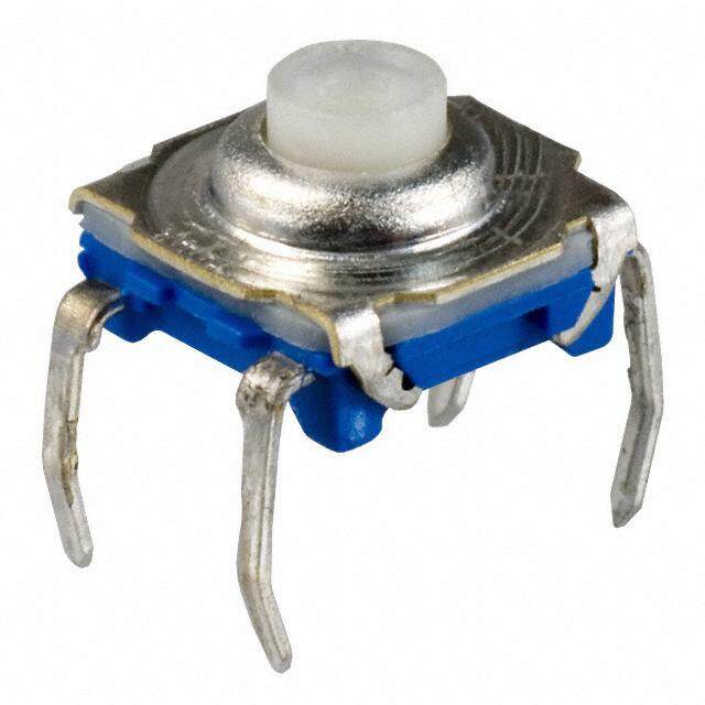
ICGOO电子元器件商城为您提供B3F-4000由Omron Electronics LLC设计生产,在icgoo商城现货销售,并且可以通过原厂、代理商等渠道进行代购。 B3F-4000价格参考¥1.30-¥1.30。Omron Electronics LLCB3F-4000封装/规格:触摸开关, 顶部触动 触摸开关 SPST-NO 通孔。您可以下载B3F-4000参考资料、Datasheet数据手册功能说明书,资料中有B3F-4000 详细功能的应用电路图电压和使用方法及教程。
Omron Electronics Inc-EMC Div的B3F-4000触摸开关是一种高灵敏度、耐用性好的电子开关,广泛应用于各种工业和消费类设备中。以下是其主要应用场景:

1. 家用电器:B3F-4000常用于现代家用电器的控制面板,如微波炉、电饭煲、洗衣机等,提供简洁美观的操作界面,用户只需轻触即可实现功能选择或参数调节。

2. 工业设备:在工业自动化领域,该型号的触摸开关可用于操作面板、人机界面(HMI)以及各种机械设备的启动/停止控制,具备良好的抗干扰能力和稳定性。

3. 医疗设备:由于其高可靠性与易于清洁的特点,B3F-4000也适用于医疗仪器,例如监护仪、超声波设备等,确保精确操作的同时满足卫生要求。

4. 照明系统:在智能照明领域,这种触摸开关被用来控制灯光的开关及亮度调节,适合办公室、商场或家庭环境使用。

5. 电梯和自动门:作为电梯楼层按钮或自动门开启/关闭控制的一部分,B3F-4000能够承受频繁操作并保持稳定性能。

6. 公共设施:如自助终端机、售票机等公共场所设备上也有应用,提供直观便捷的操作体验。

7. 安防系统:可用于监控摄像头、报警装置等的安全设置切换,保障系统运行安全可靠。

总之,B3F-4000凭借其小巧设计、低功耗特性以及出色的环境适应能力,在众多需要高效、简便输入方式的产品中发挥重要作用。
| 参数 | 数值 |
| 产品目录 | |
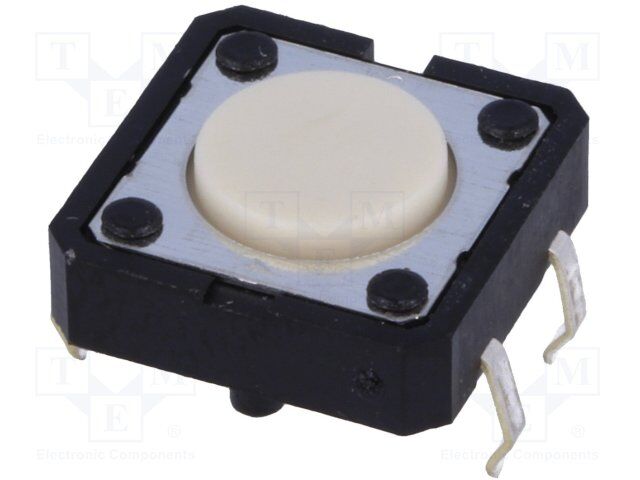
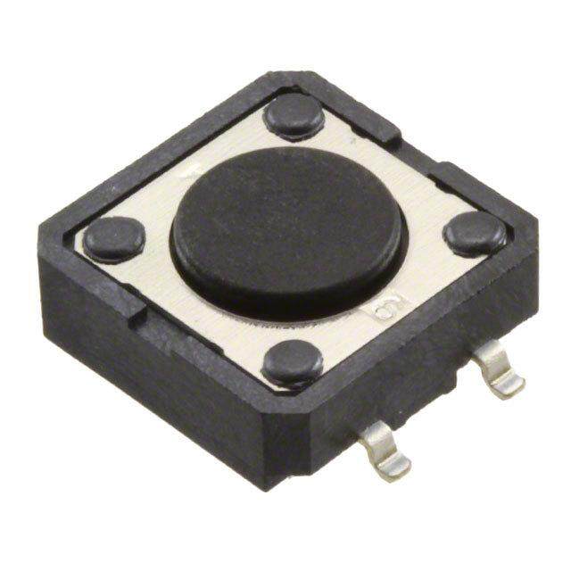
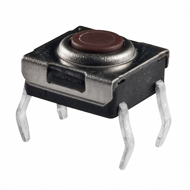
| 描述 | SWITCH TACTILE SPST-NO 0.05A 24V触觉开关 12x12mm Std Ht 4.3 Gen Purpose 130g |
| 产品分类 | |
| 品牌 | Omron Electronics |
| 产品手册 | |
| 产品图片 |
|
| rohs | 符合RoHS无铅 / 符合限制有害物质指令(RoHS)规范要求 |
| 产品系列 | 触觉开关,Omron Electronics B3F-4000B3F |
| mouser_ship_limit | 该产品可能需要其他文件才能进口到中国。 |
| 数据手册 | |
| 产品型号 | B3F-4000 |
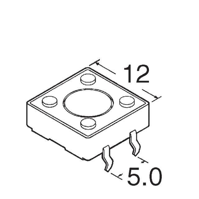
| PCB外致动器高度(从引脚计算) | 4.30mm |
| PCN设计/规格 | |
| 不同电压时的触头额定电流 | 0.05A @ 24VDC |
| 产品培训模块 | http://www.digikey.cn/PTM/IndividualPTM.page?site=cn&lang=zhs&ptm=25458 |
| 产品目录绘图 |
|
| 产品目录页面 | |
| 产品种类 | 触觉开关 |
| 作用力 | 130gf |
| 侵入防护 | - |
| 其它名称 | B3F-4000S |
| 其它有关文件 | |
| 包装 | 散装 |
| 商标 | Omron Electronics |
| 外形 | 12.00mm x 12.00mm |
| 安装方向 | Straight |
| 安装类型 | 通孔 |
| 安装风格 | Through Hole |
| 工作力 | 1.3 N |
| 工作温度 | -25°C ~ 70°C |
| 工作温度范围 | - 25 C to + 70 C |
| 工厂包装数量 | 100 |
| 开关功能 | 关-瞬时 |
| 开关行程 | 0.30mm |
| 执行器 | Round |
| 接地端子 | No |
| 晶体管管座高度 | 4.3 mm |
| 机械寿命 | 3,000,000 次循环 |
| 标准包装 | 100 |
| 照明 | 不发光 |
| 照明电压(标称值) | - |
| 照明类型,颜色 | - |
| 特性 | - |
| 电压额定值DC | 24 V |
| 电流额定值 | 50 mA |
| 电路 | SPST-NO |
| 端子类型 | PC 引脚 |
| 端接类型 | Solder Pin |
| 系列 | B3F |
| 致动器方向 | 顶部触动 |
| 致动器材料 | - |
| 致动器类型 | 标准 |
| 触点形式 | SPST |
| 触点电镀 | Silver |
| 零件号别名 | B3F-4000-BY-OMZ B3F4000BYOMZ |


- 商务部:美国ITC正式对集成电路等产品启动337调查
- 曝三星4nm工艺存在良率问题 高通将骁龙8 Gen1或转产台积电
- 太阳诱电将投资9.5亿元在常州建新厂生产MLCC 预计2023年完工
- 英特尔发布欧洲新工厂建设计划 深化IDM 2.0 战略
- 台积电先进制程称霸业界 有大客户加持明年业绩稳了
- 达到5530亿美元!SIA预计今年全球半导体销售额将创下新高
- 英特尔拟将自动驾驶子公司Mobileye上市 估值或超500亿美元
- 三星加码芯片和SET,合并消费电子和移动部门,撤换高东真等 CEO
- 三星电子宣布重大人事变动 还合并消费电子和移动部门
- 海关总署:前11个月进口集成电路产品价值2.52万亿元 增长14.8%

PDF Datasheet 数据手册内容提取
Tactile Switch B3F Through-hole-mounting Switches in a Wide Range of Models: 6 × 6 mm, 12 × 12 mm, Side-operated Models, Gold-plated Contacts, and Radial Tape • Extended mechanical/electrical durability: 10x106 operations for 12x12 mm type and 1x10⁶ operations for the 6 x 6 mm type (cid:129) Taped radial type, vertical type and high force types are available. (cid:129) Gold plated models available for increased contact reliability, resistance to corrosive gas and insulation failure prevention for ion migration in harsh environments (cid:129) B32-series Key Tops mount to models with projected plungers. RoHS Compliant ■ List of Models 6 × 6 mm Models Type Contact Plunger Height Operating Plunger Bags material force (OF) color Without ground Minimum With ground Minimum terminal packing unit terminal packing unit Standard: Silver 4.3 mm 0.98 N {100 gf} lvory B3F-1000 B3F-1100 Flat type B3F-1000 plated 1.47 N {150 gf} Yellow B3F-1002 B3F-1102 Series 2.55 N {260 gf} Orange B3F-1005 B3F-1105 4.9 N {500 gf} Red B3F-1006 --- 5.0 mm 0.98 N {100 gf} Black B3F-1020 B3F-1120 1.47 N {150 gf} Gray B3F-1022 B3F-1122 2.55 N {260 gf} Pink B3F-1025 B3F-1125 4.9 N {500 gf} Blue B3F-1026 --- 5.0 mm 0.98 N {100 gf} Black --- B3F-1110 (7.5-mm pitch) 7.0 mm 0.98 N {100 gf} Black B3F-1060 100 pcs --- 100 pcs 1.47 N {150 gf} Yellow B3F-1062 --- 9.5 mm 0.98 N {100 gf} Black B3F-1070 --- 1.47 N {150 gf} Yellow B3F-1072 --- 2.55 N {260 gf} Orange B3F-1075 --- 7.3 mm 0.98 N {100 gf} lvory B3F-1050 B3F-1150 Projected type 1.47 N {150 gf} Yellow B3F-1052 B3F-1152 2.55 N {260 gf} Orange B3F-1055 B3F-1155 4.9 N {500 gf} Red B3F-1056 --- 1
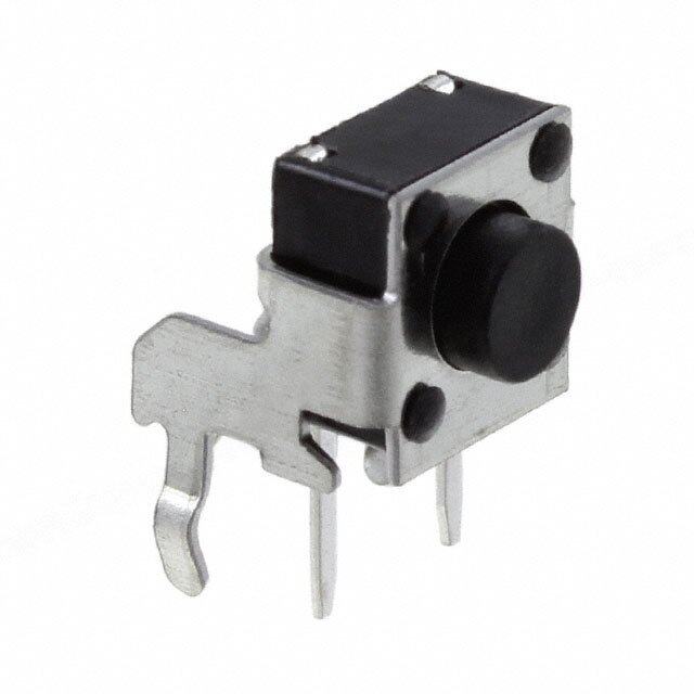
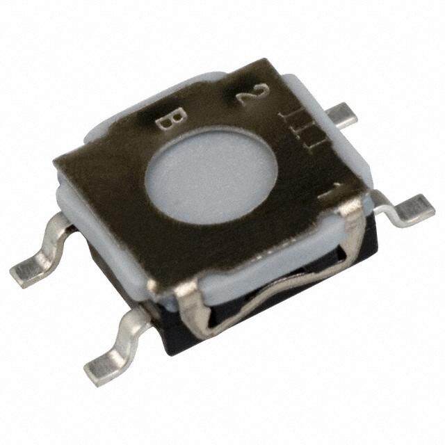
B3F B3F Type Contact Plunger Height Operating Plunger Bags material force (OF) color Without ground Minimum With ground Minimum terminal packing unit terminal packing unit Side- Silver 3.15 mm 0.98 N {100 gf} lvory --- B3F-3100 Flat type operated: plated 1.47 N {150 gf} Yellow --- B3F-3102 B3F-3000 2.55 N {260 gf} Orange --- B3F-3105 Series 3.85 mm 0.98 N {100 gf} Black --- B3F-3120 1.47 N {150 gf} Gray --- B3F-3122 2.55 N {260 gf} Pink --- B3F-3125 6.15 mm 0.98 N {100 gf} lvory --- B3F-3150 Projected type 1.47 N {150 gf} Yellow --- B3F-3152 2.55 N {260 gf} Orange --- B3F-3155 High- Gold 4.3 mm 1.76 N {180 gf} Yellow B3F-1002-G B3F-1102-G Flat type reliability plated 5.0 mm Gray B3F-1022-G B3F-1122-G gold-plated: B3F-1000-G 7.0 mm Yellow B3F-1062-G 100 pcs --- 100 pcs Series (see note) 9.5 mm Yellow B3F-1072-G --- (see note) Side- 7.3 mm Yellow B3F-1052-G --- Projected type operated with highly reliable gold-plated: B3F-3000-G Series 3.85 mm Gray --- B3F-3122-G Flat type (see note) Note: Bulk Packaged, 100 Switches per bag. Order in multiples of the package quantity. 12 × 12 mm Models Type Contact Plunger Height Operating Plunger Bags material (or LED color) force (OF) color Without ground Minimum With ground Minimum terminal packing unit terminal packing unit Standard: Silver Flat type 4.3 mm 1.27 N {130 gf} lvory B3F-4000 B3F-4100 B3F-4000 plated 2.55 N {260 gf} Yellow B3F-4005 B3F-4105 Series Projected type 7.3 mm 1.27 N {130 gf} lvory B3F-4050 B3F-4150 2.55 N {260 gf} Yellow B3F-4055 B3F-4155 Long durability: Silver Flat type 4.3 mm 1.27 N {130 gf} Blue B3F-5000 B3F-5100 100 pcs 100 pcs B3F-5000 Se- plated Projected type 7.3 mm Blue B3F-5050 B3F-5150 ries High reliability Gold Flat type 4.3 mm 1.27 N {130 gf} Blue B3F-5001 B3F-5101 gold-plated: plated B3F-5001 Projected type 7.3 mm Blue B3F-5051 B3F-5151 Series Note: Bulk Packaged, 100 switches per bag. Order in multiples of the package quantity. 6 × 6 mm Radial Models (Taping Specifications) Type Contact Plunger Height Operating Plunger Taped Radial material force (OF) color Without ground Minimum With ground Minimum terminal packing unit terminal packing unit Taped Silver Flat type 4.3 mm 0.98 N {100 gf} lvory B3F-6000 B3F-6100 Radial: plated 1.47 N {150 gf} Yellow B3F-6002 B3F-6102 B3F-6000 5.0 mm 0.98 N {100 gf} Black B3F-6020 B3F-6120 Series 1,000 pcs 1,000 pcs 1.47 N {150 gf} Gray B3F-6022 B3F-6122 Projected type 7.3 mm 0.98 N {100 gf} lvory B3F-6050 B3F-6150 1.47 N {150 gf} Yellow B3F-6052 B3F-6152 Note: The switches are tape packaged in units of 1,000 per package. Order in multiples of the package size. Switches are not sold individually. 2
B3F B3F ■ Ratings/Characteristics Rating (resistive load) 1 to 50 mA, 3 to 24 VDC (B3F-G: 100 μA to 50 mA, 3 to 24 VDC) Minimum applicable load (reference value) 10 μA at 1 VDC (resistive load) Ambient operating temperature -25°C to +70°C at 60%RH max. (with no icing or condensation) Ambient operating humidity 35% to 85% (at +5 to +35°C) Contact form SPST-NO Contact resistance (initial value) 100 mΩ max. Insulation resistance 100 MΩ min. (at 250VDC with insulation tester) Dielectric strength 500 VAC, 50/60 Hz for 1 min Bounce time 5 ms max. Vibration resistance Malfunction: 10 to 55 Hz, 1.5 mm double amplitude Shock resistance Destruction: 1,000 m/s2 {approx. 100G} max. Malfunction: 100 m/s2 {approx. 10G} max. Durability B3F-1000, B3F-3000, B3F-6000: 1,000,000 operations min (OF: 0.98 N {100 gf}) (B3F-1070: 500,000 operations min) 300,000 operations min (OF: 1.47 N {150 gf}) 100,000 operations min (OF: 2.55 N {260 gf}) 50,000 operations min (OF: 4.9 N {500 gf}) B3F-4000: 3,000,000 operations min (OF: 1.27 N {130 gf}) 1,000,000 operations min (OF: 2.55 N {260 gf}) B3F-5000/5001: 10,000,000 operations min. B3F-G: 300,000 operations min. Weight 6 × 6 mm models: approx. 0.25 g 12 × 12 mm models (standard types): approx. 0.85 g Radial models: approx. 0.25 g Degree of protection IEC IP00 Washing Not possible ■ Operating Characteristics 6 × 6 mm Models B3F-1000, B3F-3000, B3F-6000 B3F-G Operating force (OF) 0.98 N 1.47 N 2.55 N 4.9 N 1.76 N B3F-1@@0 B3F-1@@2 B3F-1@@5 B3F-10@6 B3F-1@@2-G Item B3F-3@@0 B3F-3@@2 B3F-3@@5 B3F-3@@2-G B3F-6@@0 B3F-6@@2 Operating force (OF) 0.98±0.29 N 1.47±0.49 N 2.55±0.69 N 4.9±1.47 N 1.76±0.49 N {100±30 gf} {150±50 gf} {260±70 gf} {500±150 gf} {180±50 gf} Releasing force (RF) 0.2 N {20 gf} min. 0.49 N {50 gf}min. 0.49 N {50 gf}min. 0.7 N {70 gf} min. 0.49 N {50 gf}min. Pretravel (PT) 0.25+0.2/–0.1 mm 0.25+0.2/–0.1 mm 12 × 12 mm Models B3F-4000, B3F-5000, B3F-5001 Operating force (OF) 1.27 N 2.55 N B3F-4@@0 B3F-4@@5 Item B3F-5@@0 B3F-5@@1 Operating force (OF) 1.27±0.49 N 2.55±0.69 N {130±50 gf} {260±70 gf} Releasing force (RF) 0.29 N {30 gf} min. 0.49 N {50 gf} min. Pretravel (PT) 0.3+0.2/–0.1 mm 3
B3F B3F ■ Dimensions (Unit: mm) Note: The numbers used for terminals in the following graphics are indicated in the “Bottom View” diagram below. In this 2 1 diagram, the Switch is rotated so that the terminals are on the right and left-hand sides, and the OMRON logo ap- 4 3 pears the right way up. (Except Side-operated and Radial Models) (Bottom View) 6 × 6 mm Models Standard, Flat Plunger Type Standard, Flat Plunger Type (without Ground Terminal) (with Ground Terminal) B3F-1000, B3F-1002, B3F-1005, B3F-1006 B3F-1100, B3F-1102, B3F-1105 B3F-1020 (See note.), B3F-1022 (See note.), B3F-1120 (See note.), B3F-1122 (See note.) B3F-1025 (See note.), B3F-1026 (See note.) B3F-1125 (See note.) B3F-1002-G, B3F-1022-G (See note.) B3F-1102-G, B3F-1122-G (See note.) PCB Processing Dimensions PCB Processing Dimensions (Reference Only) (Top View) (Reference Only) (Top View) 6±0.2 (PCB thickness, t=1.6) 6±0.2 (PCB thickness, t=1.6) 6±0.2 4.5±0.2 6±0.2 4.5±0.2 4.5±0.1 4.5±0.1 4.1±0.1 1.5 3.5 6.5±0.1 Four, 1±0.1 dia. dia. Five, 1±0.05 dia. 3.5 dia. (See note.) 6.5±0.1 (See note.) Terminal Arrangement/ 4.3±0.2 3.4 Terminal Arrangement/Internal 4.3±0.2 3.4 Internal Connections (Top View) Connections (Top View) 3.5 3.5 4 3 0.3 4 3 0.3 0.7 0.7 0.7 76..75±±00..55 0.7 0.7 2 1 67..57±±00..55 0.3 2 1 Note: The height of B3F-1020, B3F-1022, B3F-1025, Note: The height of B3F-1120, B3F-1122, and 5 and B3F-1026 is 5±0.2 mm. B3F-1125 is 5±0.2 mm. Standard, Flat Plunger Type Standard, Flat Plunger Type (with Ground Terminal, Pitch: 7.5 mm) (without Ground Terminal) B3F-1060, B3F-1062, B3F-1062-G B3F-1110 PCB Processing Dimensions PCB Processing Dimensions (Reference Only) (Top View) (Reference Only) (Top View) (PCB thickness, t=1.6) (PCB thickness, t=1.6) 6±0.2 6±0.2 6±0.2 4.5±0.2 4.5±0.1 6±0.2 4.5±0.2 4.5±0.1 4.1±0.1 Four, 3.5 1.5 1±0.05 dia. 1.2±0.05 dia. dia. 6.5±0.1 Four, 3.5 7.5±0.1 0.5 max. 1±0.05 dia. dia. 7±0.2 Terminal Arrangement/Internal 3.4 5±0.2 3.4 Connections (Top View) (1.8) Terminal Arrangement/ 3.5 Internal Connections 4 3 0.3 3.5 (Top View) 0.3 6.5±0.5 7.7±0.5 0.7 0.7 4 3 0.7 0.7 0.7 2 1 79.5±0±.05.5 0.3 5 2 1 Note: Unless otherwise specified, a tolerance of ±0.4 mm applies to all dimensions. No terminal numbers are indicated on the Switches. 4
B3F B3F Standard, Flat Plunger Type Standard, Projected Plunger Type (without Ground Terminal) (without Ground Terminal) B3F-1070, B3F-1072, B3F-1075, B3F-1072-G B3F-1050, B3F-1052 B3F-1055, B3F-1056 PCB Processing Dimensions B3F-1052-G PCB Processing Dimensions (Reference Only) (Top View) (Reference Only) (Top View) (PCB thickness, t=1.6) (PCB thickness, t=1.6) 6±0.2 6±0.2 6±0.2 4.5±0.2 4.5±0.1 6±0.2 4.5±0.2 4.5±0.2 3.5 dd3iiaa.. 6.5±0.1 F1±o0u.0r5, .dia 2.4 × 2.4±0.1 3.5 dia. 6.5±0.1 F1±o0u.0r5, dia. 0.5 max. Terminal Arrangement/Internal 1.8±0.1 Terminal Arrangement/Internal 9.5 Connections (Top View) 7.3±0.2 Connections (Top View) 3.4 4.3±0.2 3.4 (1.8) 4 3 4 3 3.5 3.5 0.3 0.3 6.5±0.5 2 1 6.5±0.5 2 1 7.7±0.5 0.7 0.7 7.7±0.5 0.7 0.7 Standard, Projected Plunger Type Side-operated, Flat Plunger Type (with Ground Terminal) B3F-3100, B3F-3102, B3F-3105 B3F-1150, B3F-1152, B3F-1155 PCB Processing Dimensions PCB Processing Dimensions (Reference Only) (Top View) (Reference Only) (Top View) (PCB thickness, t=1.6) 7.3 (PCB thickness, t=1.6) 6±0.2 Two, 1.5±0.05 dia. 6.25 6±0.2 4.5±0.2 4.5±0.1 2.5±0.1 4.1±0.1 3.5 dia. 1.5 Five, 1±0.05 dia. 4.5±0.1 2.4 × 2.4±0.1 3.5 dia. 7±0.1 Two, 6.5±0.1 1±0.05 dia. 1.8±0.1 Terminal Arrangement/ 7.4 Terminal Arrangement/ 7.3±0.2 Internal Connections 4 Internal Connections 4.3±0.2 3.4 (Top View) 3.5 (Top View) 4 3 4 3.5 0.3 3 0.3 0.7 4.5±0.5 0.3 1 1 2 67..057.±±700..55 0.30.7 0.7 2 5 1 78±.07.5 3.21.52±50.2 2.5±0.5 Side-operated, Flat Plunger Type (Height: 3.85 mm) Side-operated, Projected Plunger Type B3F-3120, B3F-3122, B3F-3125, B3F-3122-G B3F-3150, B3F-3152, B3F-3155 PCB Processing Dimensions PCB Processing Dimensions 7.3 (Reference Only) (Top View) 7.3 (Reference Only) (Top View) (PCB thickness, t=1.6) (PCB thickness, t=1.6) 6.25 Two, 1.5±0.05 dia. 6.25 Two, 1.5±0.05 dia. 2.5±0.1 2.5±0.1 3.5 dia. 4.5±0.1 4.5±0.1 3.5 dia. 7±0.1 Two, 7±0.1 Two, 1±0.05 dia. 1±0.05 dia. 7.4 Terminal Arrangement/ 7.4 2.4 × 2.4±0.1 Terminal Arrangement/ 4 Internal Connections 4 Internal Connections (Top View) (Top View) 3.5 4 3.5 4 3 3 0.3 0.7 0.3 1 0.3 4.5±0.5 2.25 1 2 0.7 4.5±0.5 0.3 1.8±0.1 1 1 2 78±.07.5 3.85±0.2 2.5±0.5 78±.07.5 6.15±20..225 2.5±0.5 Note: Unless otherwise specified, a tolerance of ±0.4 mm applies to all dimensions. No terminal numbers are indicated on the Switches. 5
B3F B3F 12 × 12 mm Models Standard, Long-durability, Standard, Long-durability, and High-reliability Models and High-reliability Models Flat Plunger Type Flat Plunger Type (without Ground Terminal) (with Ground Terminal) B3F-4100, B3F-4105, B3F-4000, B3F-4005, B3F-5100, B3F-5101 B3F-5000, B3F-5001 PCB Processing Dimensions PCB Processing Dimensions (Reference Only) (Top View) (Reference Only) (Top View) (PCB thickness, t=1.6) (PCB thickness, t=1.6) Two, 1.8±0.05 dia. T(fworo ,p 1o.s8it±i0o.n05in dgia b.oss) 12±0.2 (for positioning boss) 12±0.2 5±0.1 9±0.1 5±0.1 9±0.1 12±0.2 5±0.2 12±0.2 5±0.2 6.9±0.1 Five, 12.5±0.1 F1.o2u±r0,. 05 dia. 1.6 12.5±0.1 1.2±0.05 dia. Terminal Arrangement/ Terminal Arrangement/ 7.1 dia. Internal Connections 7.1 dia. Internal Connections (Top View) (Top View) 4.3±0.2 3.5 4.3±0.2 3.5 3.5 4 3 3.5 4 3 1.6 dia. 0.3 1 1 0.9 0.3 1 1 1.6 dia. 12.5±0.5 9±0.1 2 1 12.5±0.5 6.9 2 1 13.8±0.5 13.8±0.5 9±0.1 5 Standard, Long-durability, Standard, Long-durability, and High-reliability Models and High-reliability Models Projected Plunger Type Projected Plunger Type (without Ground Terminal) (with Ground Terminal) B3F-4050, B3F-4055, B3F-4150, B3F-4155, B3F-5050, B3F-5051 B3F-5150, B3F-5151 PCB Processing Dimensions PCB Processing Dimensions (Reference Only) (Top View) (Reference Only) (Top View) (PCB thickness, t=1.6) (PCB thickness, t=1.6) 12±0.2 T(fworo ,p 1o.s8it±i0o.n05in dgia b.oss) 12±0.2 (Tfworo ,p 1o.s8it±i0o.n05in dgia b.oss) 5±0.1 9±0.1 12±0.2 5±0.2 5±0.1 9±0.1 12±0.2 5±0.2 6.9±0.1 1.6 Five, @3.8±0.1 12.5±0.1 F1.o2u±r0,. 05 dia. @3.8±0.1 12.5±0.1 1.2±0.05 dia. 7.1 dia. 7.1 dia. 1.8±0.2 TInetremrninaal lC Aornrnanecgteiomnesn t/ 1.8±0.2 TInetremrninaal lC Aornrnanecgteiomnesn t/ 7.3±0.24.3±0.2 3.5 (Top View) 7.3±0.24.3±0.2 3.5 (Top View) 3.5 4 3 3.5 4 3 1.6 dia. 0.3 1 1 0.9 0.3 1 1 1.6 dia. 12.5±0.5 9±0.1 2 1 12.5±0.5 6.9 2 1 13.8±0.5 13.8±0.5 9±0.1 5 Note: Unless otherwise specified, a tolerance of ±0.4 mm applies to all dimensions. 6
B3F B3F Note: The numbers used for terminals in the following graphics are indicated in the “Bottom View” diagram below. In this 1 diagram, the Switch is rotated so that the terminals are on the right and left-hand sides, and the OMRON logo appears the right way up. 2 6 mm × 6 mm Radial Types (Taping Specifications): Sold in Units of 1,000 Switches (Bottom View) Flat Plunger Type 6±0.3 Surface B (without Ground Terminal) B3F-6000, B3F-6002 6±0.3 12.7±1 6.35±1 2 max. 3.5 dia. Surface A 0.5 max. Support (1) 4.3 3.4 0.9 tape 0.5 max.918 0+1 0.2 max. 6 9±0.5 0.5 5 -0+.20.8 0.3 18 -0+.51 4 dia. ±0.2 Terminal Arrangement Note: The tape is random P(RCeBfe Preronccees Osninlyg) D(Timope nVsieiown)s /(ITnotper Vniaelw C)onnections 12.7±0.3 Carrier tape (PCB thickness, t=1.6) between surface A and surface B. Two, 1 +00.1 d ia. 5±0.1 2 1 Flat Plunger Type 6±0.3 12.7±1 (with Ground Terminal) 6.35±1 2 max. B3F-6100, B3F-6102 6±0.3 2 3.5 dia. 0.5 max. Stauppeport 0.5 max.11 0.9 20±0.5 (1) 4.3 3.4 6 9±0.5 3.1 0.2 dia. 18 -0+.51 0.5 5±0.2 0.3 5 -0+.20.8 0.6 4±0.2 dia. PCB Processing Dimensions Terminal Arrangement 12.7±0.3 Carrier tape (Reference Only) (Top View) /Internal Connections (PCB thickness, t=1.6) (Top View) Three, 1 +0.01 d ia. 5±0.1 2 1 3 5±0.1 Flat Plunger Type (without Ground Terminal) 6±0.3 Surface B B3F-6020, B3F-6022 6±0.3 6.351±21.7±1 2 max. 3.5 dia. Surface A 0.5 max. Stauppeport 0.5 max.9 18 0+1 0.9 (1) 5 3.4 6 9±0.5 0.2 max. 18 -0+.51 0.5 5 -0+.20.8 0.3 4±0.2 dia. Note: The tape is random PCB Processing Dimensions T/Ienrtmerinnaall CAorrnannegcetimonesnt 12.7±0.3 Carrier tape between surface A (Reference Only) (Top View) (Top View) and surface B. (PCB thickness, t=1.6) Two, 1 +0.01 d ia. 5±0.1 2 1 Note: Unless otherwise specified, a tolerance of ±0.4 mm applies to all dimensions. No terminal numbers are indicated on the Switches. 7
B3F B3F Flat Plunger Type 6±0.3 (with Ground Terminal) B3F-6120, B3F-6122 6±0.3 2 6.351±21.7±1 2 max. 3.5 dia. 0.5 max. (1) 5 3.4 0.9 Stauppeport 0.5 max.11 20±0.5 3.1 0.2 max. 6 9±0.5 0.5 5±0.2 0.3 5 -0+.20.8 0.6 18 -0+.51 4±0.2 dia. PCB Processing Dimensions Terminal Arrangement ((RPCefBe rtehniccken Oesnsly, )t =(T1o.6p) View) /(ITnotper Vniaelw C)onnections 12.7±0.3 Carrier tape Three, 1+00.1 d ia. 5±0.1 2 1 3 5±0.1 Projected Plunger Type (without Ground Terminal) 6±0.3 Surface B B3F-6050, B3F-6052 6±0.3 3.5 dia. Surface A 2.4 6.351±21.7±1 2 max. 0.5 max. 7.3 0.9 (1) 3.4 Support 9 tape 0.5 dia. 18 +01 0.2 max. 0.5 5 -0+.20.8 0.3 6 9±0.5 18 -0+.51 PCB Processing Dimensions Terminal Arrang ement (Reference Only) (Top View) /Internal Connections 4±0.2 dia. (PCB thickness, t=1.6) (Top View) 12.7±0.3 Carrier tape Two, 1+00.1 d ia. 5±0.1 2 1 Note: The tape is random between surface A and surface B. Projected Plunger Type (with Ground Terminal) 6±0.3 B3F-6150, B3F-6152 6±0.3 2 6.351±21.7±1 2 max. 3.5 dia. 2.4 0.5 max. 7.3 0.9 (1) 3.4 Support 11 tape 0.5 max. 20±0.5 3.1 0.2 max. 0.5 5±0.2 0.3 6 9±0.5 5 +-0.02.8 0.6 18 -0+.51 PCB Processing Dimensions Terminal Arrangement 4±0.2 dia. (Reference Only) (Top View) /Internal Connections (PCB thickness, t=1.6) (Top View) 12.7±0.3 Carrier tape Three, 1 +00.1 d ia. 5±0.1 2 1 3 5±0.1 Note: Unless otherwise specified, a tolerance of ±0.4 mm applies to all dimensions. No terminal numbers are indicated on the Switches. 8
B3F B3F ■ Key Tops B32-series Key Tops are available for projected plungers. Refer to the Datasheet of B32 for details. ■ Precautions Be sure to read the safety precautions common to all Tactile Switches for correct use. (cid:129) Application examples provided in this document are for reference only. In actual applications, confirm equipment functions and safety before using the product. (cid:129) Consult your OMRON representative before using the product under conditions which are not described in the manual or applying the product to nuclear control systems, railroad systems, aviation systems, vehicles, combustion systems, medical equipment, amusement machines, safety equipment, and other systems or equipment that may have a serious influence on lives and property if used improperly. Make sure that the ratings and performance characteristics of the product provide a margin of safety for the system or equipment, and be sure to provide the system or equipment with double safety mechanisms. Note: Do not use this document to operate the Unit. OMRON Corporation Electronic and Mechanical Components Company Contact: www.omron.com/ecb Cat. No. A070-E1-08 1014(0207)(O) 9
Mouser Electronics Authorized Distributor Click to View Pricing, Inventory, Delivery & Lifecycle Information: O mron: B3F-3100 B3F-1150 B3F-1152 B3F-4100 B3F-4155 B3F-1100 B3F-6000 B3F-4000 B3F-4050 B3F-4055 B3F- 4005 B3F-1070 B3F-1050 B3F-1052 B3F-1000 B3F-1020 B3F-1002 B3F-1022 B3F-3120 B3F-3122 B3F-3150 B3F-3152 B3F-3155 B3F-4055S B3F-1025 B3F-1055 B3F-1102 B3F-1105 B3F-1120 B3F-1122 B3F-1125 B3F- 1110 B3F-1155 B3F-3102 B3F-3105 B3F-3125 B3F-1002-G B3F-1022-G B3F-1102-G B3F-1122-G B3F-5001 B3F-4105 B3F-5100 B3F-5150 B3F-5101 B3F-5151 B3F-6002 B3F-6020 B3F-6022 B3F-6050 B3F-6052 B3F- 6100 B3F-6102 B3F-6120 B3F-6150 B3F-6152 B3F-1006 B3F-1026 B3F-1056 B3F-1060 B3F-1072 B3F-1075 B3F-1170 B3F-1172 B3F-6025 B3F-6055 B3F-5050 B3F-1005 B3F-4150 B3F-5000 B3F-1062 B3F-5051 B3F- 1000S B3F-1002S B3F-6005-A