ICGOO在线商城 > 连接器,互连器件 > 矩形连接器 - 阵列,边缘型,夹层式(板对板) > AXN430330P
 Datasheet下载
- 型号: AXN430330P
- 制造商: Panasonic Corporation
- 库位|库存: xxxx|xxxx
- 要求:
| 数量阶梯 | 香港交货 | 国内含税 |
| +xxxx | $xxxx | ¥xxxx |
查看当月历史价格
查看今年历史价格
AXN430330P产品简介:
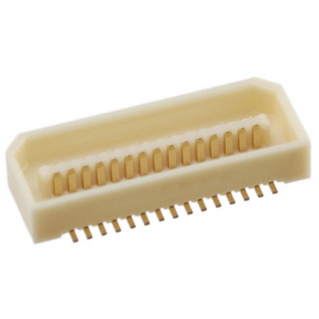
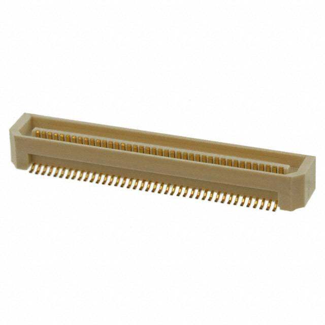
ICGOO电子元器件商城为您提供AXN430330P由Panasonic Corporation设计生产,在icgoo商城现货销售,并且可以通过原厂、代理商等渠道进行代购。 AXN430330P价格参考。Panasonic CorporationAXN430330P封装/规格:矩形连接器 - 阵列,边缘型,夹层式(板对板), 30 位置 连接器 接头,外罩触点 表面贴装 金。您可以下载AXN430330P参考资料、Datasheet数据手册功能说明书,资料中有AXN430330P 详细功能的应用电路图电压和使用方法及教程。
Panasonic Electric Works 的型号 AXN430330P 是一种矩形连接器,属于阵列、边缘型、夹层式(板对板)类别。以下是其主要应用场景:

 1. 消费电子设备
   - 该连接器广泛应用于需要高密度信号传输的消费电子产品,例如笔记本电脑、平板电脑、智能电视和多媒体播放器等。
   - 它适合用于主板与子板之间的信号和电源连接,支持高效的电路互联。

 2. 工业控制设备
   - 在工业自动化领域,AXN430330P 可用于 PLC(可编程逻辑控制器)、人机界面(HMI)以及传感器模块的内部连接。
   - 其紧凑设计和高可靠性使其成为工业环境中复杂电路的理想选择。

 3. 通信设备
   - 此型号适用于路由器、交换机、基站和其他通信设备中的板对板连接。
   - 它能够提供稳定的信号传输性能,满足高速数据处理需求。

 4. 医疗设备
   - 在医疗仪器中,如超声波设备、监护仪和诊断装置,AXN430330P 能够实现精确的数据采集和传输。
   - 其低接触电阻和高耐久性确保了设备的长期稳定运行。

 5. 汽车电子
   - 该连接器可用于车载信息娱乐系统、导航模块和高级驾驶辅助系统(ADAS)中的电路连接。
   - 其抗震性和抗干扰能力使其在严苛的汽车环境中表现出色。

 6. 测试与测量设备
   - 在测试仪器和测量设备中,AXN430330P 提供可靠的电气连接,支持多通道信号传输。
   - 它的高精度特性非常适合实验室和生产环境中的精密测量任务。

 特点总结:
- 高密度设计:节省空间,适合小型化设备。
- 多触点配置:支持多种信号类型(如电源、数据和控制信号)。
- 耐用性强:具备良好的插拔寿命和抗腐蚀性能。
- 兼容性好:易于集成到各种复杂的电子系统中。

综上所述,AXN430330P 主要应用于需要高效、可靠且紧凑的板对板连接场景,涵盖消费电子、工业、通信、医疗、汽车及测试测量等多个领域。
| 参数 | 数值 |
| 产品目录 | |
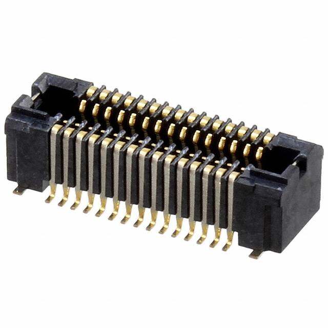
| 描述 | CONN HEADER .8MM 30POS SMD |
| 产品分类 | 矩形 - 板对板连接器 - 阵列,边缘型,夹层式 |
| 品牌 | Panasonic Electric Works |
| 数据手册 | |
| 产品图片 |
|
| 产品型号 | AXN430330P |
| PCN过时产品 | |
| rohs | 无铅 / 符合限制有害物质指令(RoHS)规范要求 |
| 产品系列 | P8 |
| 其它名称 | 255-3025-1 |
| 其它有关文件 | |
| 包装 | 剪切带 (CT) |
| 安装类型 | 表面贴装 |
| 排数 | 2 |
| 接合堆叠高度 | 3mm,3.5mm,6mm |
| 板上高度 | 0.107"(2.72mm) |
| 标准包装 | 1 |
| 特性 | 板导轨 |
| 特色产品 | http://www.digikey.com/cn/zh/ph/Panasonic/ToughContact.html |
| 触头镀层 | 金 |
| 触头镀层厚度 | - |
| 连接器类型 | 接头,外罩触点 |
| 配套产品 | /product-detail/zh/AXN330130P/255-3019-6-ND/2364773/product-detail/zh/AXN330038P/255-3018-6-ND/2364772/product-detail/zh/AXN330130P/255-3019-1-ND/2364733/product-detail/zh/AXN330038P/255-3018-1-ND/2364732/product-detail/zh/AXN330C238S/AXN330C238S-ND/2049344/product-detail/zh/AXN330C238P/AXN330C238P-ND/2049343/product-detail/zh/AXN330C238J/AXN330C238J-ND/2049342/product-detail/zh/AXN330C130S/AXN330C130S-ND/2049341/product-detail/zh/AXN330C130P/AXN330C130P-ND/2049340/product-detail/zh/AXN330C038S/AXN330C038S-ND/2049339/product-detail/zh/AXN330C038P/AXN330C038P-ND/2049338/product-detail/zh/AXN330C038J/AXN330C038J-ND/2049337/product-detail/zh/AXN330238S/AXN330238S-ND/2049336/product-detail/zh/AXN330238P/AXN330238P-ND/2049335/product-detail/zh/AXN330238J/AXN330238J-ND/2049334/product-detail/zh/AXN330130S/255-4050-5-ND/2049333/product-detail/zh/AXN330130P/255-3019-2-ND/2049332/product-detail/zh/AXN330038S/255-4051-5-ND/2049331/product-detail/zh/AXN330038P/255-3018-2-ND/2049330/product-detail/zh/AXN330038J/AXN330038J-ND/2049329 |
| 针脚数 | 30 |
| 间距 | 0.031"(0.80mm) |


-30DS-0.4V(53).jpg)
-20DP-0.4V(53).jpg)
.jpg)

- 商务部:美国ITC正式对集成电路等产品启动337调查
- 曝三星4nm工艺存在良率问题 高通将骁龙8 Gen1或转产台积电
- 太阳诱电将投资9.5亿元在常州建新厂生产MLCC 预计2023年完工
- 英特尔发布欧洲新工厂建设计划 深化IDM 2.0 战略
- 台积电先进制程称霸业界 有大客户加持明年业绩稳了
- 达到5530亿美元!SIA预计今年全球半导体销售额将创下新高
- 英特尔拟将自动驾驶子公司Mobileye上市 估值或超500亿美元
- 三星加码芯片和SET,合并消费电子和移动部门,撤换高东真等 CEO
- 三星电子宣布重大人事变动 还合并消费电子和移动部门
- 海关总署:前11个月进口集成电路产品价值2.52万亿元 增长14.8%
-80DS-0.5V(51).jpg)
-40DS-0.5V(81).jpg)
PDF Datasheet 数据手册内容提取
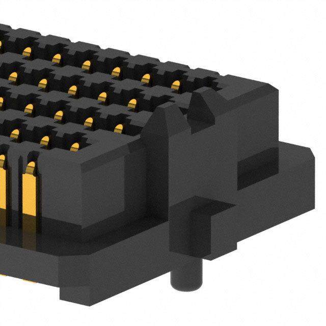
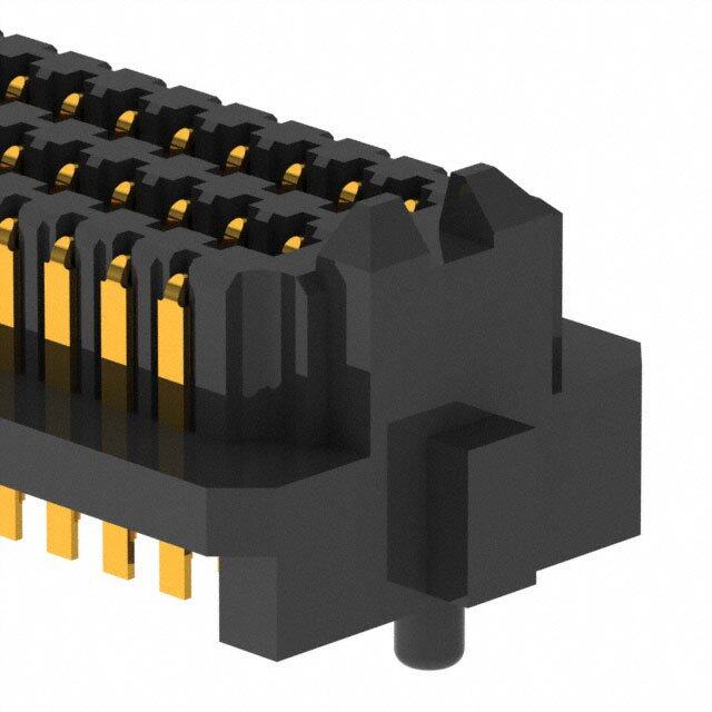
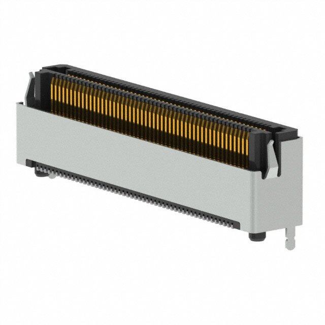
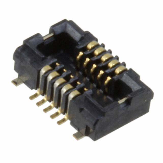
Automation Controls Catalog For board-to-board P8 Narrow pitch connectors Series (0.8mm pitch) FEATURES 1. The product lineup includes low 5. Automatic mounting profile heights of 3.0 mm, 3.5 mm, 1) Automatic mounting machine is 4.0 mm, 4.5 mm, 5.0 mm, 5.5 mm, available with an exclusive mounting 6.0 mm, 7.0 mm, 8.0 mm, 13.0 mm and nozzle. 5.88mm Socket 6.83mm Header 14.0 mm. Using the following types of suction 2. Ideal for portable devices, the nozzles make the connectors compatible bellows-type contacts provide a with automatic mounting without the need strong resistance against falling, for suction tape. RoHS compliant impacts, and forced insertions and removals. Bellows-type contacts Bellows-type contacts resist mating stress and offer high contact reliability. Ex.: Stacking height of 3.0 mm The bellows type contacts are fabricated by bending thin sheet metal. They offer a reliable contact since a rounded corner, Suction tape and covers are also instead of a sharp edge, available for compatibility with other types is used for tuning fork type contact. of mounting machines. Round corner makes contact. 3. Porosity treatment for improved resistance against corrosion. 4. Simple lock mechanism Suction tape (socket) Lock mechanism ensures proper contact and provides resistance against 2) Positioning bosses (without bosses vibrations and shocks. also available) Simple locking mechanism Bosses for positioning on the PC board (those without bosses are also available). Suitable for both manual and automatic mounting. APPLICATIONS Digital devices, such as desktop PC, laptop and digital video cameras 2013.11 industrial.panasonic.com/ac/e/ –1– ©Panasonic Corporation 2013 ACCTB25E 201310-T
P8 Narrow pitch connectors (0.8mm pitch) ORDERING INFORMATION AXN 3: Narrow Pitch Connector P8 (0.8 mm pitch) Socket 4: Narrow Pitch Connector P8 (0.8 mm pitch) Header Number of pins (2 digits) Suction tape and cover Nil:Socket; without suction tape, Header; without suction cover C: Socket; with suction tape, Header; with suction cover Mated height <Socket> 0: For mated height 3.0 mm, 4.0 mm and 5.0 mm 1: For mated height 6.0 mm, 7.0 mm, 8.0 mm, 13.0 mm and 14.0 mm 2: For mated height 3.5 mm, 4.5 mm and 5.5 mm <Header> 0: For mated height 13.0 mm 1: For mated height 14.0 mm 3: For mated height 3.0 mm, 3.5 mm and 6.0 mm 4: For mated height 4.0 mm, 4.5 mm and 7.0 mm 5: For mated height 5.0 mm, 5.5 mm and 8.0 mm Functions 3: With positioning bosses (Except for mated height 13.0 mm header, embossed tape packing) 4: Without positioning bosses (Mated height 13.0 mm header, embossed tape packing and mated height 14.0 mm header only) Surface treatment (Contact portion / Terminal portion) <Socket> 0: Ni plating on base, Au plating on surface / Ni plating on base, Au plating on surface (Applies to mated heights of 6.0 to 14.0 mm.) 8: Ni plating on base, Au plating on surface / Ni plating on base, Au plating on surface (Applies to mated heights of 3.0 to 5.5 mm.) <Header> 0: Ni plating on base, Au plating on surface / Ni plating on base, Au plating on surface Packing J: 1,500 pieces embossed tape and paper reel × 2 P: 1,000 pieces embossed tape and paper reel × 2 S: Tube package Notes:1. The tape width for 100-pin embossed tape packaging is non-JIS standard. Please inquire. 2. The depth of the embossed tape for headers with 13 mm and 14 mm mated heights is non-JIS standard. Please test with your mounter before using. 3. Models possible for “J” packaging are as follows: Socket mated heights: 3.0 mm, 3.5 mm, 4.0 mm, 4.5 mm, 5.0 mm, and 5.5 mm Headers: Mated heights 3.0 mm, 3.5 mm, and 6.0 mm Panasonic Corporation Automation Controls Buisiness Division industrial.panasonic.com/ac/e/ –2– ©Panasonic Corporation 2013 ACCTB25E 201310-T
P8 Narrow pitch connectors (0.8mm pitch) PRODUCT TYPES Stick package Embossed tape package Mated No. of Part No. Packing quantity Part No. Packing quantity height pins Outer Inner carton Socket Header Stick Socket Header Outer carton carton (1 reel) 16 AXN316038S AXN416330S 50 pcs. 300 pcs. AXN316038* AXN416330* 20 AXN320038S AXN420330S 50 pcs. 300 pcs. AXN320038* AXN420330* 24 AXN324038S AXN424330S 30 pcs. 300 pcs. AXN324038* AXN424330* 26 AXN326038S AXN426330S 30 pcs. 300 pcs. AXN326038* AXN426330* 30 AXN330038S AXN430330S 30 pcs. 300 pcs. AXN330038* AXN430330* 3.0 mm 40 AXN340038S AXN440330S 25 pcs. 300 pcs. AXN340038* AXN440330* 50 AXN350038S AXN450330S 20 pcs. 300 pcs. AXN350038* AXN450330* 60 AXN360038S AXN460330S 15 pcs. 300 pcs. AXN360038* AXN460330* 80 AXN380038S AXN480330S 12 pcs. 300 pcs. AXN380038* AXN480330* 100 AXN300038S AXN400330S 12 pcs. 300 pcs. — — 16 AXN316238S AXN416330S 50 pcs. 300 pcs. AXN316238* AXN416330* 24 AXN324238S AXN424330S 30 pcs. 300 pcs. AXN324238* AXN424330* 3.5 mm 26 AXN326238S AXN426330S 30 pcs. 300 pcs. AXN326238* AXN426330* 30 AXN330238S AXN430330S 30 pcs. 300 pcs. AXN330238* AXN430330* 60 AXN360238S AXN460330S 15 pcs. 300 pcs. AXN360238* AXN460330* 16 AXN316038S AXN416430S 50 pcs. 300 pcs. AXN316038* AXN416430P 20 AXN320038S AXN420430S 50 pcs. 300 pcs. AXN320038* AXN420430P 26 AXN326038S AXN426430S 30 pcs. 300 pcs. AXN326038* AXN426430P 30 AXN330038S AXN430430S 30 pcs. 300 pcs. AXN330038* AXN430430P 4.0 mm 40 AXN340038S AXN440430S 25 pcs. 300 pcs. AXN340038* AXN440430P 50 AXN350038S AXN450430S 20 pcs. 300 pcs. AXN350038* AXN450430P 60 AXN360038S AXN460430S 15 pcs. 300 pcs. AXN360038* AXN460430P 80 AXN380038S AXN480430S 12 pcs. 300 pcs. AXN380038* AXN480430P 100 AXN300038S AXN400430S 12 pcs. 300 pcs. — — 16 AXN316238S AXN416430S 50 pcs. 300 pcs. AXN316238* AXN416430P 26 AXN326238S AXN426430S 30 pcs. 300 pcs. AXN326238* AXN426430P 4.5 mm 30 AXN330238S AXN430430S 30 pcs. 300 pcs. AXN330238* AXN430430P 60 AXN360238S AXN460430S 15 pcs. 300 pcs. AXN360238* AXN460430P 14 AXN314038S AXN414530S 50 pcs. 300 pcs. AXN314038* AXN414530P Note 1) Note 1) 20 AXN320038S AXN420530S 50 pcs. 300 pcs. AXN320038* AXN420530P “Asterisk” mark on “Asterisk” mark on end of part No.; end of part No.; 24 AXN324038S AXN424530S 30 pcs. 300 pcs. AXN324038* AXN424530P J: 1,500 pieces J: 3,000 pieces 26 AXN326038S AXN426530S 30 pcs. 300 pcs. AXN326038* AXN426530P (recommendation) (recommendation) 30 AXN330038S AXN430530S 30 pcs. 300 pcs. AXN330038* AXN430530P P: 1,000 pieces P: 2,000 pieces 5.0 mm 40 AXN340038S AXN440530S 25 pcs. 300 pcs. AXN340038* AXN440530P 50 AXN350038S AXN450530S 20 pcs. 300 pcs. AXN350038* AXN450530P 60 AXN360038S AXN460530S 15 pcs. 300 pcs. AXN360038* AXN460530P 80 AXN380038S AXN480530S 12 pcs. 300 pcs. AXN380038* AXN480530P 100 AXN300038S AXN400530S 12 pcs. 300 pcs. — — 24 AXN324238S AXN424530S 30 pcs. 300 pcs. AXN324238* AXN424530P 26 AXN326238S AXN426530S 30 pcs. 300 pcs. AXN326238* AXN426530P 5.5 mm 30 AXN330238S AXN430530S 30 pcs. 300 pcs. AXN330238* AXN430530P 60 AXN360238S AXN460530S 15 pcs. 300 pcs. AXN360238* AXN460530P 20 AXN320130S AXN420330S 50 pcs. 300 pcs. AXN320130P AXN420330* 24 AXN324130S AXN424330S 30 pcs. 300 pcs. AXN324130P AXN424330* 26 AXN326130S AXN426330S 30 pcs. 300 pcs. AXN326130P AXN426330* 30 AXN330130S AXN430330S 30 pcs. 300 pcs. AXN330130P AXN430330* 40 AXN340130S AXN440330S 25 pcs. 300 pcs. AXN340130P AXN440330* 6.0 mm 50 AXN350130S AXN450330S 20 pcs. 300 pcs. AXN350130P AXN450330* 60 AXN360130S AXN460330S 15 pcs. 300 pcs. AXN360130P AXN460330* 64 AXN364130S AXN464330S 15 pcs. 300 pcs. AXN364130P AXN464330* 80 AXN380130S AXN480330S 12 pcs. 300 pcs. AXN380130P AXN480330* 100 AXN300130S AXN400330S 12 pcs. 300 pcs. — — 20 AXN320130S AXN420430S 50 pcs. 300 pcs. AXN320130P AXN420430P 22 AXN322130S AXN422430S 30 pcs. 300 pcs. AXN322130P AXN422430P 26 AXN326130S AXN426430S 30 pcs. 300 pcs. AXN326130P AXN426430P 30 AXN330130S AXN430430S 30 pcs. 300 pcs. AXN330130P AXN430430P 7.0 mm 40 AXN340130S AXN440430S 25 pcs. 300 pcs. AXN340130P AXN440430P 50 AXN350130S AXN450430S 20 pcs. 300 pcs. AXN350130P AXN450430P 60 AXN360130S AXN460430S 15 pcs. 300 pcs. AXN360130P AXN460430P 80 AXN380130S AXN480430S 12 pcs. 300 pcs. AXN380130P AXN480430P 100 AXN300130S AXN400430S 12 pcs. 300 pcs. — — Panasonic Corporation Automation Controls Buisiness Division industrial.panasonic.com/ac/e/ –3– ©Panasonic Corporation 2013 ACCTB25E 201310-T
P8 Narrow pitch connectors (0.8mm pitch) Stick package Embossed tape package Mated No. of Part No. Packing quantity Part No. Packing quantity height pins Outer Inner carton Socket Header Stick Socket Header Outer carton carton (1 reel) 20 AXN320130S AXN420530S 50 pcs. 300 pcs. AXN320130P AXN420530P 22 AXN322130S AXN422530S 30 pcs. 300 pcs. AXN322130P AXN422530P 24 AXN324130S AXN424530S 30 pcs. 300 pcs. AXN324130P AXN424530P 26 AXN326130S AXN426530S 30 pcs. 300 pcs. AXN326130P AXN426530P 30 AXN330130S AXN430530S 30 pcs. 300 pcs. AXN330130P AXN430530P 1,000 pcs. 2,000 pcs. 8.0 mm 34 AXN334130S AXN434530S 30 pcs. 300 pcs. AXN334130P AXN434530P 40 AXN340130S AXN440530S 25 pcs. 300 pcs. AXN340130P AXN440530P 50 AXN350130S AXN450530S 20 pcs. 300 pcs. AXN350130P AXN450530P 60 AXN360130S AXN460530S 15 pcs. 300 pcs. AXN360130P AXN460530P 80 AXN380130S AXN480530S 12 pcs. 300 pcs. AXN380130P AXN480530P 100 AXN300130S AXN400530S 12 pcs. 300 pcs. — — — — 20 AXN320130S AXN420030S 50 pcs. 300 pcs. AXN320130P AXN420040P Note 6) 30 AXN330130S AXN430030S 30 pcs. 300 pcs. AXN330130P AXN430040P Note 6) 40 AXN340130S AXN440030S 25 pcs. 300 pcs. AXN340130P AXN440040P Note 6) Socket: 1,000 pcs. Socket: 2,000 pcs. 13.0 mm 50 AXN350130S AXN450030S 20 pcs. 300 pcs. AXN350130P AXN450040P Note 6) Header: 500 pcs. Header: 1,000 pcs. 60 AXN360130S AXN460030S 15 pcs. 300 pcs. AXN360130P AXN460040P Note 6) 80 AXN380130S AXN480030S 12 pcs. 300 pcs. AXN380130P AXN480040P Note 6) Socket: 1,000 pcs. Socket: 2,000 pcs. 14.0 mm 20 AXN320130S AXN420130S 50 pcs. 300 pcs. AXN320130P AXN420130P Header: 400 pcs. Header: 800 pcs. Notes:1.Please add following suffix at * marked positions. J: Inner carton (1 reel) 1,500 pcs. (Outer carton: 3,000 pcs.) P: Inner carton (1 reel) 1,000 pcs. (Outer carton: 2,000 pcs.) In order to reduce the amount of packaging materials used to help protect the global environment, it is recommended that each packaging box contains 1,500 units with the “J” product number suffix. As for the part No. P is suffixed, only 1,000 pcs. reel is available. 2.Regarding ordering units: During production: Please make orders in 1-reel units. Samples for mounting confirmation: Available in units of 50 pieces. Please contact our sales office. Samples: Please order it by a stick unit. 3.Connectors with suction tape and suction cover are also available. Socket: Suction tape, Header: Suction cover. For this type of connector, insert the letter “C” between the 6th and 7th column of the ordering number. Example: For a 20 pin contact socket with 3mm mated height (embossed tape package): AXN320C038P 4.The standard type comes with positioning bosses. Connectors without positioning bosses are available for on-demand production (3,000 pcs./lot or more). Please inquire. 5.Since the embossed tape width of 100 pin contact connectors packaged with embossed tape exceeds the JIS standard, please consult us. 6.Headers that have 13.0 mm mated height and embossed tape packaging do not come with positioning bosses. The depth of the embossed tape for headers with 13.0 mm and 14.0 mm mated heights is non-JIS compliant. Please test with your mounter before using. Panasonic Corporation Automation Controls Buisiness Division industrial.panasonic.com/ac/e/ –4– ©Panasonic Corporation 2013 ACCTB25E 201310-T
P8 Narrow pitch connectors (0.8mm pitch) SPECIFICATIONS 1. Characteristics Item Specifications Conditions Rated current 0.5A Rated voltage 60V AC/DC Electrical Breakdown voltage 250V AC for 1 minute Detection current: 1mA characteristics Insulation resistance Min. 1,000MΩ Using 500V DC megger Contact resistance Max. 60mΩ Based on the contact resistance measurement method specified by JIS C 5402. Composite insertion force Max. 43.1N (30 pin contacts) Mechanical Composite removal force Min. 6.37N (30 pin contacts) characteristics 40 pin contacts or less: Min. 1.96N Measuring the maximum force. Contact holding force 50 pin contacts or more: Min. 0.981N As the contact & post is axially pull out. Ambient temperature –55°C to +85°C No freezing at low temperatures Max. peak temperature of 245°C (on the surface of the PC board Soldering heat resistance Infrared reflow soldering around the connector terminals) 300°C within 5 seconds Soldering iron –55°C to +85°C (product only) No freezing at low temperatures. Storage temperature –40°C to +50°C (standard packing) No dew condensation. Conformed to MIL-STD-202F, method 107G Order Temperature (°C) Time (minutes) Thermal shock resistance 5 cycles, insulation resistance min. 100MΩ, 1 –55−03 30 (header and socket mated) contact resistance max. 60mΩ 2 Max. 5 Environmental 3 85+30 30 characteristics 4 Max. 5 –55−03 Humidity resistance 120 hours, insulation resistance min. 100MΩ, Bath temperature 40±2°C, (header and socket mated) contact resistance max. 60mΩ humidity 90 to 95% R.H. Saltwater spray resistance 24 hours, insulation resistance min. 100MΩ, Bath temperature 35±2°C, (header and socket mated) contact resistance max. 60mΩ saltwarter concentration 5±1% Bath temperature 40±2°C, H2S resistance 48 hours, contact resistance max. 60mΩ gas concentration 3±1 ppm, (header and socket mated) humidity 75 to 80% R.H. Bath temperature 40±2°C, SO2 resistance 48 hours, contact resistance max. 60mΩ gas concentration 10±3 ppm, (header and socket mated) humidity 90 to 95% R.H. Lifetime Repeated insertion and removal speed of Insertion and removal life 50 times characteristics max. 200 times/hours Mated height 3mm 30 pin contacts; Socket: 0.26g Header: 0.26g Unit weight 50 pin contacts; Socket: 0.40g Header: 0.44g 2. Material and surface treatment Part name Material Surface treatment Molded portion Heat-resistant resin (UL94V-0) — Contact portion: Ni plating on base, Au plating on surface Contact/Post Copper alloy Terminal portion: Ni plating on base, Au plating on surface (Except for thick of terminal) Panasonic Corporation Automation Controls Buisiness Division industrial.panasonic.com/ac/e/ –5– ©Panasonic Corporation 2013 ACCTB25E 201310-T
P8 Narrow pitch connectors (0.8mm pitch) DIMENSIONS (Unit: mm) The CAD data of the products with a CAD Data mark can be downloaded from: http://industrial.panasonic.com/ac/e/ • Mated height 3.0mm, 4.0mm, 4.5mm, 5.0mm, 5.5mm, 6.0mm, 7.0mm, 8.0mm, 13.0mm, 14.0mm type 1) Socket CAD Data Terminal coplanarity B±0A.15 F C1.0 000..38.8500±±0±00..11.1 G ±1.950.10.98 Dimension table (mm) 93 88 4. 5. No. of A B C D E F pins 1146 98..0200 54..6800 77..9100 77..9100 54..6800 +0.240–0.1 0. 20 10.60 7.20 9.50 9.50 7.20 0.8±0.05 dia. 22 11.40 8.00 10.30 10.30 8.00 C±0.1 Recommended PC board pattern 24 12.20 8.80 11.10 11.10 8.80 0.10 (TOP VIEW) General tolerance: ±0.3 26 13.00 9.60 11.90 11.90 9.60 E±0.05 30 14.60 11.20 13.50 13.50 11.20 0.80±0.05 34 16.20 12.80 15.10 15.10 12.80 0.80±0.05 40 18.60 15.20 17.50 17.50 15.20 0.50±0.05 50 23.40 19.20 21.50 21.50 19.20 1 8 6604 2297..0400 2243..8200 2275..1500 2275..1500 2243..8200 0.15 ±950.1 ±3.320. Min.6.3 80 35.40 31.20 33.50 33.50 31.20 1. D±0.05 100 43.40 39.20 41.50 41.50 39.20 2-0.9+ 00 . 1 dia. hole Mated height G 3.0mm, 4.0mm, 5.0mm common 2.20 3.5mm, 4.5mm, 5.5mm common 2.70 6.0mm, 7.0mm, 8.0mm, 13.0mm, 14.0mm common 5.20 2) Header CAD Data A Terminal coplanarity B±0.15 F 0.80±0.1 1 00..3850±±00..11 G ±950. 1. Dimension table (mm) 5 33 No. of 9 28 A B C D E F 5. 5.6. pins 1146 1 09..0255 54..6800 77..9100 77..9100 54..6800 +0.20–0.1 C1.10 4 20 11.65 7.20 9.50 9.50 7.20 0. 22 12.45 8.00 10.30 10.30 8.00 0.8±0.05 dia. 24 13.25 8.80 11.10 11.10 8.80 0.10 C±0.1 Recommended PC board pattern 26 14.05 9.60 11.90 11.90 9.60 General tolerance: ±0.3 (TOP VIEW) 30 15.65 11.20 13.50 13.50 11.20 D±0.05 34 17.25 12.80 15.10 15.10 12.80 E±0.05 0.80±0.05 40 19.65 15.20 17.50 17.50 15.20 0.80±0.05 50 25.85 19.20 21.50 21.50 19.20 0.50±0.05 60 29.85 23.20 25.50 25.50 23.20 1680400 343157...488555 233491...822000 243713...155000 243713...155000 233491...822000 N0o.1te5) ±1.950.1 ±4.430.1 Min.7.33 Note:The 13 mm mated height (20 to 80 pin contacts) terminal flatness is 0.1 mm. 2-0.9+ 00 . 1 dia. hole Mated height G 3.0mm, 3.5mm, 6.0mm common 2.72 4.0mm, 4.5mm, 7.0mm common 3.72 5.0mm, 5.5mm, 8.0mm common 4.72 13.0mm 10.14 14.0mm 11.14 Panasonic Corporation Automation Controls Buisiness Division industrial.panasonic.com/ac/e/ –6– ©Panasonic Corporation 2013 ACCTB25E 201310-T
P8 Narrow pitch connectors (0.8mm pitch) 3) Socket and header are mated 6.83 B +–00.3 Dimension table (mm) A No. of pins A Mated height B 14 9.25 3.0mm 3.00 16 10.05 3.5mm 3.50 20 11.65 4.0mm 4.00 22 12.45 4.5mm 4.50 24 13.25 5.0mm 5.00 26 14.05 5.5mm 5.50 30 15.65 6.0mm 6.00 34 17.25 7.0mm 7.00 40 19.65 8.0mm 8.00 50 25.85 13.0mm 13.00 60 29.85 14.0mm 14.00 64 31.45 Note:Common for all mated 80 37.85 heights. 100 45.85 EMBOSSED TAPE DIMENSIONS (unit: mm, Common for respective contact type, socket and header) • Tape dimensions (Conforming to JIS C 0806:1990. • Paper reel dimensions (Conforming to JIS C 0806-1990) However, some tapes have mounting hole pitches that do not comply with the standard.) Tape I Tape II A±0.3 A±0.3 E+20 C B Label 1.75 C 1.75 Top cover tape 4 4 Pull out direction D2 Pull out direction D2 F Emboss carrier tape 1.5+ 00 . 1 dia. 1.5+ 00 . 1 dia. Panasonic Corporation Automation Controls Buisiness Division industrial.panasonic.com/ac/e/ –7– ©Panasonic Corporation 2013 ACCTB25E 201310-T
P8 Narrow pitch connectors (0.8mm pitch) Dimension table (mm) (1) Suffix: J (1 reel, 1,500 pieces embossed tape package) Mated height No. of pins Type of taping A B C D E F Quantity per reel 14 to 32 Tape I 24.0 — 11.5 12.0 24.4 370 dia. Socket: 3.0mm, 3.5mm, 4.0mm, 34 to 40 Tape II 32.0 28.4 14.2 12.0 32.4 370 dia. 4.5mm, 5.0mm, 5.5mm 1,500 pcs. Header: 3.0mm, 3.5mm, 6.0mm 50 to 60 Tape II 44.0 40.4 20.2 12.0 44.4 370 dia. 80 Tape II 56.0 52.4 26.2 12.0 56.4 370 dia. (2) Suffix: P (1 reel, 1,000, 500, 350 and 250 pieces embossed tape package) Mated height No. of pins Type of taping A B C D E F Quantity per reel 14 to 32 Tape I 24.0 — 11.5 12.0 24.4 330 dia. Socket: 3.0mm, 3.5mm, 4.0mm, 4.5mm, 5.0mm, 5.5mm 34 to 40 Tape II 32.0 28.4 14.2 12.0 32.4 330 dia. 1,000 pcs. Header: 3.0mm, 3.5mm, 4.0mm, 50 to 60 Tape II 44.0 40.4 20.2 12.0 44.4 330 dia. 4.5mm, 6.0mm, 7.0mm 80 Tape II 56.0 52.4 26.2 12.0 56.4 330 dia. 14 to 32 Tape I 24.0 — 11.5 12.0 24.4 370 dia. Socket: 6.0mm, 7.0mm, 8.0mm, 34 to 40 Tape II 32.0 28.4 14.2 12.0 32.4 370 dia. 13.0mm, 14.0mm 1,000 pcs. Header: 5.0mm, 5.5mm, 8.0mm 50 to 60 Tape II 44.0 40.4 20.2 12.0 44.4 370 dia. 80 Tape II 56.0 52.4 26.2 12.0 56.4 370 dia. 20 Tape I 24.0 — 11.5 16.0 24.4 370 dia. 500 pcs. 30 Tape I 24.0 — 11.5 16.0 24.4 370 dia. 500 pcs. 40 Tape II 32.0 28.4 14.2 16.0 32.4 370 dia. 500 pcs. Header: 13.0mm 50 Tape II 44.0 40.4 20.2 16.0 44.4 370 dia. 500 pcs. 60 Tape II 44.0 40.4 20.2 16.0 44.4 370 dia. 500 pcs. 80 Tape II 56.0 52.4 26.2 16.0 56.4 370 dia. 500 pcs. Header: 14.0mm 20 Tape I 24.0 — 11.5 16.0 24.4 370 dia. 400 pcs. Connector orientation with respect to direction of progress of embossed tape Type Direction Common for P8 of tape progress Socket Header This corner is oriented on the C side. This corner is oriented on the C side. Please refer to the latest product specifications when designing your product. Panasonic Corporation Automation Controls Buisiness Division industrial.panasonic.com/ac/e/ –8– ©Panasonic Corporation 2013 ACCTB25E 201310-T
Notes on Using Narrow pitch Connectors Notes on Using Narrow pitch Connectors Regarding the design of devices and PC board patterns 1)When connecting several connectors 5)For all connectors of the narrow pitch backside of the FPC board to which the together by stacking, make sure to series, to prevent the PC board from connector is being connected. Please maintain proper accuracy in the design of coming off during vibrations or impacts, make the reinforcement board structure and mounting equipment so and to prevent loads from falling directly dimensions bigger than the outer limits of that the connectors are not subjected to on the soldered portions, be sure to the recommended PC board pattern twisting and torsional forces. design some means to fix the PC board (should be approximately 1 mm greater 2)With mounting equipment, there may in place. than the outer limit). be up to a ±0.2 to 0.3-mm error in Example) Secure in place with screws Material should be glass epoxy or positioning. Be sure to design PC boards polyimide, and the thickness should be Screw and patterns while taking into between 0.2 and 0.3 mm. consideration the performance and (2) Collisions, impacts, or turning of FPC abilities of the required equipment. Spacer Connector PC board boards, may apply forces on the Spacer 3) Some connectors have tabs embossed connector and cause it to come loose. on the body to aid in positioning. When Therefore, make to design retaining using these connectors, make sure that When connecting PC boards, take plates or screws that will fix the connector the PC board is designed with positioning appropriate measures to prevent the in place. holes to match these tabs. connector from coming off. 7)The narrow pitch connector series is 4)To ensure the required mechanical 6)Notes when using a FPC. designed to be compact and thin. strength when soldering the connector (1) When the connector is soldered to an Although ease of handling has been terminals, make sure the PC board FPC board, during its insertion and taken into account, take care when meets recommended PC board pattern removal procedures, forces may be mating the connectors, as displacement design dimensions given. applied to the terminals and cause the or angled mating could damage or soldering to come off. It is recommended deform the connector. to use a reinforcement board on the Regarding the selection of the connector placement machine and the mounting procedures 1)Select the placement machine taking 4)Depending on the size of the 6) Excessive mounter chucking force may into consideration the connector height, connector being used, self alignment deform the molded or metal part of the required positioning accuracy, and may not be possible. In such cases, be connector. Consult us in advance if packaging conditions. sure to carefully position the terminal with chucking is to be applied. 2)Be aware that if the catching force of the PC board pattern. the placement machine is too great, it 5)The positioning bosses give an may deform the shape of the connector approximate alignment for positioning on body or connector terminals. the PC board. For accurate positioning of 3)Be aware that during mounting, the connector when mounting it to the PC external forces may be applied to the board, we recommend using an connector contact surfaces and terminals automatic positioning machine. and cause deformations. Panasonic Corporation Automation Controls Buisiness Division industrial.panasonic.com/ac/e/ –9– ©Panasonic Corporation 2013 ACCTB48E 201303-T
Notes on Using Narrow pitch Connectors Regarding soldering 1.Reflow soldering Soldering conditions 2.Hand soldering 1)Measure the recommended profile Please use the reflow temperature profile 1)Set the soldering iron so that the tip temperature for reflow soldering by conditions recommended below for temperature is less than that given in the placing a sensor on the PC board near reflow soldering. Please contact us table below. the connector surface or terminals. (The before using a temperature profile other Table A setting for the sensor will differ depending than that described below (e.g. lead-free Product name Soldering iron temperature on the sensor used, so be sure to solder). 300°C within 5 sec. carefully read the instructions that comes •Narrow pitch connectors SMD type connectors 350°C within 3 sec. with it.) (except P8 type) 2)As for cream solder printing, screen 2)Do not allow flux to spread onto the Upper limited (Solder heat resistance) printing is recommended. Lower limited (Solder wettability) connector leads or PC board. This may 3)To determine the relationship between Temperature lead to flux rising up to the connector the screen opening area and the PC- Peak temperature 260°C Peak temperature inside. 230°C 220°C board foot pattern area, refer to the 180°C Preheating 200°C 3)Touch the soldering iron to the foot diagrams in the recommended patterns 150°C 25 sec. pattern. After the foot pattern and for PC boards and metal masks. Make 60 to 120 sec. 70 sec. connector terminal are heated, apply the sure to use the terminal tip as a reference Time solder wire so it melts at the end of the position when setting. Avoid an excessive connector terminals. •Narrow pitch connector (P8) amount of solder from being applied, ocathuesrew aisne ,i minpteerrffeercet nccoen tbayc tt.he solder will T2e4m5p°eCr amtuarxe. Peak temperatu2r0e0°C Awpirpel yh ethree solder Soldeirirnogn 155 to 165°C Preheating Terminal Terminal Small angle as Psoalsdteer 60 to 120 sec. Within 30 sec. p4o5s dseibglree ueps to PC board Time foot pattern PC board For products other than the ones above, 4)Consult us when using a screen- please refer to the latest product Pattern printing thickness other than that specifications. 4)Be aware that soldering while applying recommended. 7) The temperatures are measured at the a load on the connector terminals may 5)When mounting on both sides of the surface of the PC board near the cause improper operation of the PC board and the connector is mounting connector terminals. (The setting for the connector. on the underside, use adhesives or other sensor will differ depending on the sensor 5)Thoroughly clean the soldering iron. means to ensure the connector is used, so be sure to carefully read the 6)Flux from the solder wire may get on properly fixed to the PC board. (Double instructions that comes with it.) the contact surfaces during soldering reflow soldering on the same side is 8)The temperature profiles given in this operations. After soldering, carefully possible.) catalog are values measured when using check the contact surfaces and clean off 6)N2 reflow, conducting reflow soldering the connector on a resin-based PC any solder before use. in a nitrogen atmosphere, increases the board. When performed reflow soldering 7)For soldering of prototype devices solder flow too greatly, enabling wicking on a metal board (iron, aluminum, etc.) or during product development, you can to occur. Make sure that the solder feed a metal table to mount on a FPC, make perform soldering at the necessary rate and temperature profile are sure there is no deformation or locations by heating with a hot-air gun by appropriate. discoloration of the connector beforehand applying cream solder to the foot pattern and then begin mounting. beforehand. However, at this time, make 9)Consult us when using a screen- sure that the air pressure does not move printing thickness other than that connectors by carefully holding them recommended. down with tweezers or other similar tool. 10)Some solder and flux types may Also, be careful not to go too close to the cause serious solder or flux creeping. connectors and melt any of the molded Solder and flux characteristics should be components. taken into consideration when setting the 8)If an excessive amount of solder is reflow soldering conditions. applied during manual soldering, the solder may creep up near the contact points, or solder interference may cause imperfect contact. 3.Solder reworking 1)Finish reworking in one operation. 2)For reworking of the solder bridge, use a soldering iron with a flat tip. To prevent flux from climbing up to the contact surfaces, do not add more flux. 3) Keep the soldering iron tip temperature below the temperature given in Table A. Panasonic Corporation Automation Controls Buisiness Division industrial.panasonic.com/ac/e/ –10– ©Panasonic Corporation 2013 ACCTB48E 201303-T
Notes on Using Narrow pitch Connectors Handling Single Components 1)Make sure not to drop or allow parts to 4)Do not insert or remove the connector Excessive force applied for insertion in a fall from work bench when it is not soldered. Forcibly applied pivot action as shown may also cause 2)Excessive force applied to the external pressure on the terminals can product breakage. terminals could cause warping, come weaken the adherence of the terminals to Align the header and socket positions out, or weaken the adhesive strength of the molded part or cause the terminals to before connecting them. the solder. Handle with care. lose their evenness. 3)Repeated bending of the terminals 5)Excessive prying-force applied to one may cause terminals to break. end may cause product breakage and separation of the solder joints at the terminal. Cleaning flux from PC board 3)Since some powerful cleaning Handling the PC board solutions may dissolve molded 1)To increase the cleanliness of the •Handling the PC board after components of the connector and wipe cleaning fluid and cleaning operations, mounting the connector off or discolor printed letters, we prepare equipment for cleaning process When cutting or bending the PC board recommend aqua pura electronic parts beginning with boil cleaning, ultrasonic after mounting the connector, be careful cleaners. Please consult us if you wish to cleaning, and then vapor cleaning. that the soldered sections are subjected use other types of cleaning fluids. 2)Carefully oversee the cleanliness of to excessive force. 4)Please note that the surfaces of the cleaning fluids to make sure that the molded parts may whiten when cleaned The soldered areas should not be subjected to force. contact surfaces do not become dirty with alcohol. from the cleaning fluid itself. Storage of connectors 1)To prevent problems from voids or air Some connectors may change color 4)Avoid storing the connectors in pockets due to heat of reflow soldering, slightly if subjected to ultraviolet rays locations with excessive dust. The dust avoid storing the connectors in areas of during storage. This is normal and will not may accumulate and cause improper high humidity. When storing the affect the operation of the connector. connections at the contact surfaces. connectors for more than six months, be 3)When storing the connectors with the sure to consider storage area where the PC boards assembled and components humidity is properly controlled. alreeady set, be careful not to stack them 2)Depending on the connector type, the up so the connectors are subjected to color of the connector may vary from excessive forces. connector to connector depending on when it is produced. Other Notes 1)These products are made for the 3)Before soldering, try not to insert or 6)The connectors are not meant to be design of compact and lightweight remove the connector more than used for switching. devices and therefore the thickness of the absolutely necessary. 7)Be sure not to allow external pressure molded components has been made very 4)When coating the PC board after to act on connectors when assembling thin. Therefore, be careful during soldering the connector to prevent the PCBs or moving in block assemblies. insertion and removal operations for deterioration of insulation, perform the excessive forces applied may damage coating in such a way so that the coating the products. does not get on the connector. 2)Dropping of the products or rough 5)There may be variations in the colors mishandling may bend or damage the of products from different production lots. terminals and possibly hinder proper This is normal. reflow soldering. Panasonic Corporation Automation Controls Buisiness Division industrial.panasonic.com/ac/e/ –11– ©Panasonic Corporation 2013 ACCTB48E 201303-T
Notes on Using Narrow pitch Connectors Regarding sample orders to confirm proper mounting When ordering samples to confirm proper mounting with the placement Please refer to the latest product machine, connectors are delivered in 50- specifications when designing your piece units in the condition given right. product. Consult a sale representative for ordering sample units. Condition when delivered from manufacturing Reel (Delivery can also be made on a reel by Embossed tape Required number customer request.) of products for amount required for the mounting sample production (Unit 50 pcs.) Panasonic Corporation Automation Controls Buisiness Division industrial.panasonic.com/ac/e/ –12– ©Panasonic Corporation 2013 ACCTB48E 201303-T