ICGOO在线商城 > 继电器 > 高频 (RF) 继电器 > ARJ20A4H
 Datasheet下载
- 型号: ARJ20A4H
- 制造商: Panasonic Corporation
- 库位|库存: xxxx|xxxx
- 要求:
| 数量阶梯 | 香港交货 | 国内含税 |
| +xxxx | $xxxx | ¥xxxx |
查看当月历史价格
查看今年历史价格
ARJ20A4H产品简介:
ICGOO电子元器件商城为您提供ARJ20A4H由Panasonic Corporation设计生产,在icgoo商城现货销售,并且可以通过原厂、代理商等渠道进行代购。 ARJ20A4H价格参考。Panasonic CorporationARJ20A4H封装/规格:高频 (RF) 继电器, 。您可以下载ARJ20A4H参考资料、Datasheet数据手册功能说明书,资料中有ARJ20A4H 详细功能的应用电路图电压和使用方法及教程。
Panasonic Electric Works的ARJ20A4H是一款高频(RF)继电器,主要用于需要高频信号切换的电子设备中。该继电器具有良好的高频性能和可靠的机械寿命,适用于多种通信和测试设备。

ARJ20A4H常见的应用场景包括:

1. 通信设备:用于基站、无线接入系统等通信基础设施中,实现射频信号的切换与路由。
2. 测试测量仪器:在频谱分析仪、信号发生器等测试设备中,作为信号路径切换的关键组件。
3. 工业控制系统:在需要高频信号控制的自动化系统中,用于切换不同信号通道。
4. 广播设备:应用于广播发射系统中,实现天线切换或信号源选择。
5. 安防与监控系统:在高频监控设备中,用于信号的通断控制。

该继电器支持较高的频率范围,具备低插入损耗和高隔离度特性,适合对信号完整性要求较高的应用场合。
| 参数 | 数值 |
| 产品目录 | |
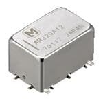
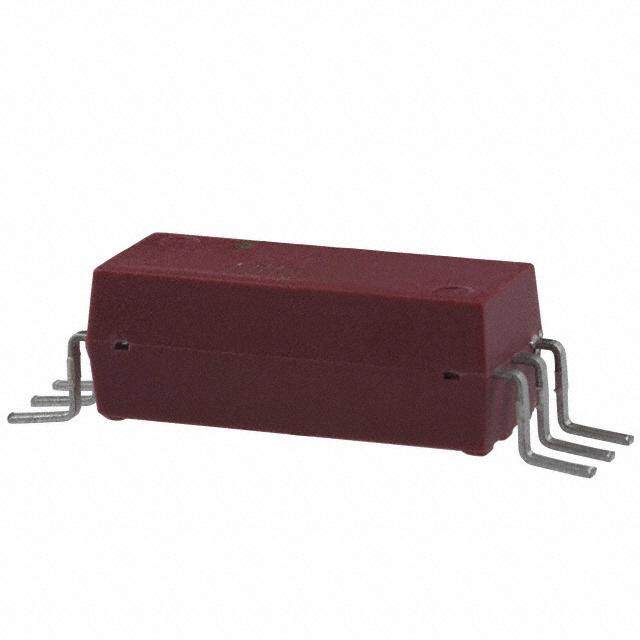
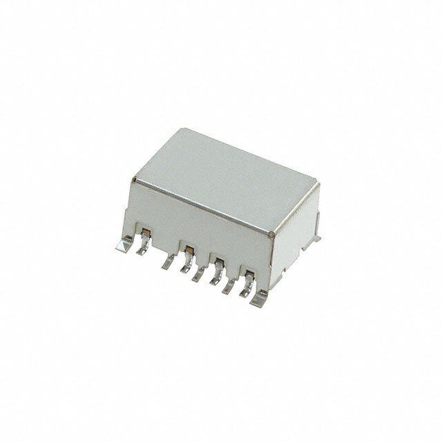
| 描述 | RELAY RF DPDT 300MA 4.5V高频/射频继电器 5GHZ DPDT 4.5VDC 300MA SMD |
| 产品分类 | |
| 品牌 | Panasonic Electric Works |
| 产品手册 | |
| 产品图片 |
|
| rohs | RoHS 合规性豁免无铅 / 符合限制有害物质指令(RoHS)规范要求 |
| 产品系列 | 高频/射频继电器,Panasonic Industrial Devices ARJ20A4HARJ |
| mouser_ship_limit | 该产品可能需要其他文件才能进口到中国。 |
| 数据手册 | |
| 产品型号 | ARJ20A4H |
| VSWR | 1.25 at 5 GHz |
| 产品目录绘图 |
|
| 产品目录页面 | |
| 产品种类 | 高频/射频继电器 |
| 介入损耗 | 0.5 dB at 5 GHz |
| 关闭电压(最小值) | 0.45 VDC |
| 其它名称 | 255-1461 |
| 其它有关文件 | |
| 功耗 | 200 mW |
| 包装 | 管件 |
| 商标 | Panasonic Industrial Devices |
| 安装类型 | 表面贴装 |
| 导通电压(最大值) | 3.38 VDC |
| 封装 | Tube |
| 工作时间 | 5ms |
| 工作温度 | -30°C ~ 70°C |
| 工厂包装数量 | 50 |
| 开关电压 | 30VDC - 最小值 |
| 最大开关电流 | 300 mA |
| 标准包装 | 50 |
| 特性 | - |
| 端子类型 | 鸥翼型 |
| 端接类型 | Solder Terminal |
| 线圈功率 | 200 mW |
| 线圈电压 | 4.5VDC |
| 线圈电流 | 44.4mA |
| 线圈电阻 | 101 欧姆 |
| 线圈类型 | 无锁存 |
| 绝缘 | 35 dB at 5 GHz |
| 继电器类型 | RF |
| 触头外形 | DPDT(2 C 型) |
| 触头材料 | 镀金 |
| 触点形式 | 2 Form C (DPDT-BM) |
| 触点电流额定值 | 300 mA |
| 触点额定值 | 300 mA |
| 释放时间 | 5ms |
| 频率 | 5 GHz |
| 额定接触(电流) | 300mA |


- 商务部:美国ITC正式对集成电路等产品启动337调查
- 曝三星4nm工艺存在良率问题 高通将骁龙8 Gen1或转产台积电
- 太阳诱电将投资9.5亿元在常州建新厂生产MLCC 预计2023年完工
- 英特尔发布欧洲新工厂建设计划 深化IDM 2.0 战略
- 台积电先进制程称霸业界 有大客户加持明年业绩稳了
- 达到5530亿美元!SIA预计今年全球半导体销售额将创下新高
- 英特尔拟将自动驾驶子公司Mobileye上市 估值或超500亿美元
- 三星加码芯片和SET,合并消费电子和移动部门,撤换高东真等 CEO
- 三星电子宣布重大人事变动 还合并消费电子和移动部门
- 海关总署:前11个月进口集成电路产品价值2.52万亿元 增长14.8%
PDF Datasheet 数据手册内容提取
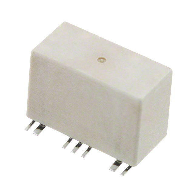
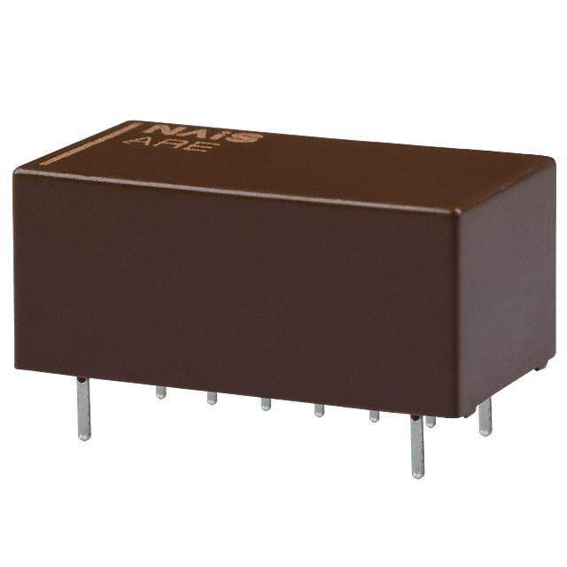
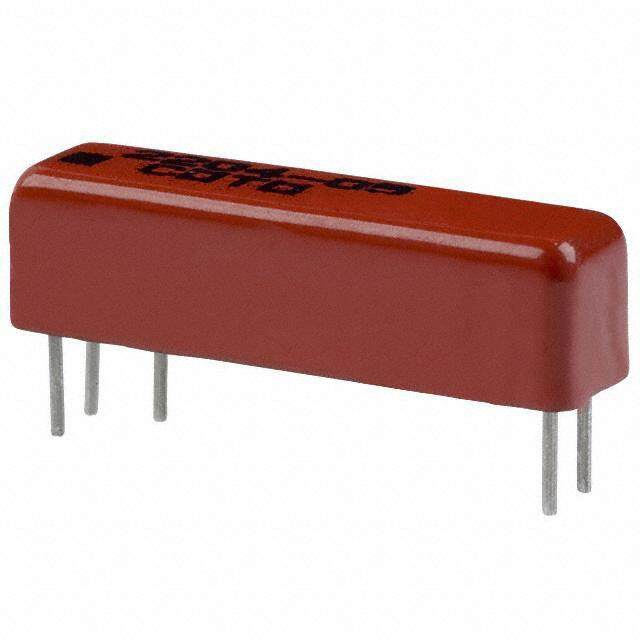
RJ (ARJ) UP TO 8GHz RJ RELAYS (ARJ) SMALL MICROWAVE RELAYS FEATURES TYPICAL APPLICATIONS • Excellent high frequency • Measuring equipment market characteristics (50Ω, at 5GHz) Attenuator circuits, spectrum analyzer, V.S.W.R.: Max. 1.25 oscilloscope, Telecommunication Insertion loss: Max. 0.5dB equipment and tester inspection. Isolation:Min. 35dB • Network communications market (Between open contacts) Microwave communication Min. 30dB • Medical instrument market (Between contact sets) • Surface mount terminal If you wish to use in applications with low Surface mount terminals are now level loads or with high frequency standard so there is much less work in switching, please consult us. designing PC boards. • Small size Size: 14.00 (L)×9.00 (W)×8.20 (H) mm RoHS compliant .551 (L)×.354 (W)×.323 (H) inch ORDERING INFORMATION ARJ 2 RJ relays Contact arrangement 2: 2 Form C Operating function 0: Single side stable 2: 2 coil latching Terminal shape Nil:Standard PC board terminal A: Surface-mount terminal Coil voltage (DC) 03: 3V, 4H: 4.5V, 12: 12V, 24: 24V (H=0.5) Packing style Nil:Carton packing X: Tape and reel packing (picked from 1/2/3-pin side) Z: Tape and reel packing (picked from 6/7/8-pin side) TYPES 1. Standard PC board terminal Contact Part No. Nominal coil voltage arrangement Single side stable 2 coil latching 3 V DC ARJ2003 ARJ2203 4.5V DC ARJ204H ARJ224H 2 Form C 12 V DC ARJ2012 ARJ2212 24 V DC ARJ2024 ARJ2224 Standard packing: 50 pcs. in an inner package; 500 pcs. in an outer package 2. Surface-mount terminal 1) Carton packing Contact Part No. Nominal coil voltage arrangement Single side stable 2 coil latching 3 V DC ARJ20A03 ARJ22A03 4.5V DC ARJ20A4H ARJ22A4H 2 Form C 12 V DC ARJ20A12 ARJ22A12 24 V DC ARJ20A24 ARJ22A24 Standard packing: 50 pcs. in an inner package; 500 pcs. in an outer package ASCTB105E 201202-T Panasonic Corporation Automation Controls Business Unit industrial.panasonic.com/ac/e/
RJ (ARJ) 2) Tape and reel packing Contact Part No. Nominal coil voltage arrangement Single side stable 2 coil latching 3 V DC ARJ20A03Z ARJ22A03Z 4.5V DC ARJ20A4HZ ARJ22A4HZ 2 Form C 12 V DC ARJ20A12Z ARJ22A12Z 24 V DC ARJ20A24Z ARJ22A24Z Standard packing: 500 pcs. in an inner package; 1,000 pcs. in an outer package Note:Tape and reel packing symbol “-Z” is not marked on the relay. “X” type tape and reel packing (picked from 1/2/3-pin side) is also available. Suffix “X” instead of “Z”. RATING 1. Coil data 1) Single side stable Nominal operating Nominal coil Pick-up voltage Drop-out voltage Coil resistance Nominal operating Max. applied voltage current voltage (at 20°C 68°F) (at 20°C 68°F) [±10%] (at 20°C 68°F) power (at 70°C 158°F) [±10%] (at 20°C 68°F) 3 V DC 66.6mA 45 Ω 4.5V DC 75%V or less of 10%V or more of 44.4mA 101.2Ω 110%V of nominal nominal voltage nominal voltage 200mW 12 V DC (Initial) (Initial) 16.6mA 720 Ω voltage 24 V DC 8.3mA 2,880 Ω 2) 2 coil latching Nominal operating Nominal coil Set voltage Reset voltage Coil resistance Nominal operating Max. applied voltage current voltage (at 20°C 68°F) (at 20°C 68°F) [±10%] (at 20°C 68°F) power (at 70°C 158°F) [±10%] (at 20°C 68°F) 3 V DC 50 mA 60 Ω 4.5V DC 75%V or less of 75%V or less of 33.3mA 135 Ω 110%V of nominal nominal voltage nominal voltage 150mW 12 V DC (Initial) (Initial) 12.5mA 960 Ω voltage 24 V DC 6.3mA 3,840 Ω 2. Specifications Characteristics Item Specifications Arrangement 2 Form C Contact Contact material Gold plating Initial contact resistance, max. Max. 150mΩ (By voltage drop 10V DC 10mA) Contact rating 1W (at 5GHz, Impedance 50Ω, V.S.W.R. 1.25) 10mA 10V DC (resistive load) Contact carrying power 1W (at 5GHz, Impedance 50Ω, V.S.W.R. 1.25) Rating Max. switching voltage 30V DC Max. switching current 0.3A DC Nominal operating power Single side stable: 200mW, 2 coil latching: 150mW V.S.W.R. Max. 1.25 High frequency Insertion loss (without D.U.T. board’s loss) Max. 0.5dB characteristics Between open contacts Min. 35dB (Initial) (~5GHz, Isolation Impedance 50Ω) Between contact sets Min. 30dB Input power 1W (at 5GHz, impedance 50Ω, V.S.W.R. 1.25, at 20°C) Min. 500MΩ (at 500V DC) Insulation resistance (Initial) Measurement at same location as “Initial breakdown voltage” section. Between open contacts 500 Vrms for 1min. (Detection current: 10mA) Breakdown Between contact sets 500 Vrms for 1min. (Detection current: 10mA) voltage Between contact and coil 500 Vrms for 1min. (Detection current: 10mA) Electrical (Initial) Between coil and earth terminal 500 Vrms for 1min. (Detection current: 10mA) characteristics Between contact and earth terminal 500 Vrms for 1min. (Detection current: 10mA) Max. 50°C (By resistive method, nominal voltage applied to the coil, 5GHz, Temperature rise (at 20°C) V.S.W.R. 1.25) Operate time [Set time] (at 20°C) Max. 5ms (Nominal operating voltage applied to the coil, excluding contact bounce time.) Max. 5ms (Nominal operating voltage applied to the coil, excluding contact bounce time.) Release time [Reset time] (at 20°C) (without diode) Shock Functional Min. 500 m/s2 (Half-wave pulse of sine wave: 6ms; detection time: 10µs.) Mechanical resistance Destructive Min. 1,000 m/s2 (Half-wave pulse of sine wave: 11ms.) characteristics Vibration Functional 10 to 55 Hz at double amplitude of 3mm (Detection time: 10µs.) resistance Destructive 10 to 55 Hz at double amplitude of 5mm Mechanical Min. 107 (at 180 cpm) Expected life Min. 106 (at 20 cpm) (1W, at 5GHz, V.S.W.R. 1.25) Electrical Min. 106 (at 20 cpm) (10mA 10V DC resistive load) Ambient temperature: –30°C to +70°C –22°F to +158°F Conditions Conditions for operation, transport and storage* Humidity: 5 to 85% R.H. (Not freezing and condensing at low temperature) Unit weight Approx. 3 g .11 oz Note:* The upper operation ambient temperature limit is the maximum temperature that can satisfy the coil temperature rise value. Refer to [6] AMBIENT ENVIRONMENT in GENERAL APPLICATION GUIDELINES. ASCTB105E 201202-T Panasonic Corporation Automation Controls Business Unit industrial.panasonic.com/ac/e/
RJ (ARJ) REFERENCE DATA 1. High frequency characteristics Sample: ARJ20A12 Measuring method: Measured with HP network analyzer (HP8510C). • V.S.W.R. characteristics • Insertion loss characteristics • Isolation characteristics (without D.U.T. board’s loss) 2.0 0 0 1.9 10 0.5 1.8 V.S.W.R.1111....4567 Insertion loss, dB11..05 Isolation, dB 23450000 Between contact sets 2.0 1.3 60 1.2 2.5 Between open contact 1.1 70 1.0 3.0 80 45MHz 5GHz 8GHz 45MHz 5GHz 8GHz 45MHz 5GHz 8GHz Frequency Frequency Frequency DIMENSIONS (mm inch) The CAD data of the products with a CAD Data mark can be downloaded from: http://industrial.panasonic.com/ac/e/ 1. Standard PC board terminal Schematic (Bottom view) CAD Data Expansion of A Single side stable 2 coil latching 10.6 .417 Direction indication Com Com 10.4 + 1 2 3 – + 1 2 3 – .409 10 4 10 4 0 to 0.2 NC NO NC NO 0 to .008 9 5 9 5 12.2 24 ribs should be soldered .480 with PC board ground. (Typical: 0.1) 8 7 6 + 8 7 6 – (Typical: .004) Com Com 14.0 9.00 .551 .354 3.50 A 3 Bmeattye br eH Fob cthaainreadc twerhisetnic sth is (Deenergized condition) (Reset condition) .138 8.20 portion is soldered with .323 PC board ground. 0.50 0.50 0.0.4160 .020 .020 8.89 3.81 .350 .150 12.70 7.62 .500 .300 11.40 0.20 .449 .008 0.50 .020 6.36 1All bottom surface of the base should be .250 touched closely or soldered with PC board ground. 0.20 0.15 .008 .006 General tolerance: ±0.3 ±.012 2. Surface mount terminal Schematic (Top view) CAD Data Expansion of A: Single side stable 2 coil latching 0.0.5200 1.401.67 Coplanarity of terminals Direction & ribs & base indication 8Co7m6 + 8Co7m6 – 10.4 3.81 .409 0.50 .150 NC9 5NO NC9 5NO .020 10 4 10 4 0.40 .016 81.3.285.920 2 4w ritihb sP sCh obuoladr db eg rsoouldnedr.ed 00 ttoo .00.028 + 1Co2m3 – + 1Co2m3 – .480 (Typical: 0.1) (Deenergized condition) (Reset condition) 14.0 9.00 (Typical: .004) .551 .354 A 3Better HF characteristics 0.0.2008 8.20 may be obtained when this .323 portion is soldered with PC board ground. 15.0 .591 10.0 .394 11.40 .449 0.50 .020 6.36 1All bottom surface of the base should be .250 touched closely or soldered with PC board ground. General tolerance: ±0.3 ±.012 Note:Please consult us regarding recommended PC board patterns. ASCTB105E 201202-T Panasonic Corporation Automation Controls Business Unit industrial.panasonic.com/ac/e/
RJ (ARJ) NOTES 1. Coil operating power 6. Conditions for operation, transport occur. Be sure to mount the relay under Pure DC current should be applied to the and storage conditions the required mounting conditions. coil. The wave form should be 1) Ambient temperature, humidity, and 7. Soldering rectangular. If it includes ripple, the ripple atmospheric pressure during usage, 1) Surface-mount terminal factor should be less than 5%. transport, and storage of the relay: In case of automatic soldering, the However, check it with the actual circuit (1) Temperature: following conditions should be observed since the characteristics may be slightly –30 to +70°C –22 to +158°F (1) Position of measuring temperature different. The nominal operating voltage (However, tolerance range is –30 to should be applied to the coil for more +60°C –22 to +140°F if package is Surface of PC board where relay is mounted. than 20 ms to set/reset the latching type carried as is.) relay. (2) Humidity: 5 to 85% RH 2. Coil connection (Avoid freezing and condensation.) (2) IR (infrared reflow) soldering method When connecting coils, refer to the wiring The humidity range varies with the diagram to prevent mis-operation or temperature. Use within the range T3 malfunction. indicated in the graph below. T2 3. External magnetic field (3) Atmospheric pressure: 86 to 106 kPa T1 Since RJ relays are highly sensitive Temperature and humidity range for polarized relays, their characteristics will usage, transport, and storage: be affected by a strong external magnetic t1 t2 Humidity, %R.H. field. Avoid using the relay under that T1 = 150 to 180°C302 to 356°F t1 = 60 to 120 sec. condition. 85 TT23 == 2W3i0th°iCn 245406°°CFa4n8d2 °hFigher t2 = Within 30 sec. 4. Cleaning Tolerance range Temperature rise of relay itself may vary For automatic cleaning, the boiling method is recommended. Avoid (Avoid freezing (Avoid according to the mounting level or the when used at condensation heating method of reflow equipment. ultrasonic cleaning which subjects the temperatures when used at lower than temperatures Therefore, please set the temperature of relays to high frequency vibrations, which 0°C32°F) higher than 0°C32°F) soldering portion of relay terminal and may cause the contacts to stick. 5 the top surface of the relay case not to It is recommended that alcoholic solvents –30 0 70 –22 +32 +158 exceed the above mentioned soldering be used. Temperature, °C°F condition. 5. Tape and reel packing 2) Condensation It is recommended to check the 1) Tape dimensions Condensation forms when there is a temperature rise of each portion under RJ relay.015.95++.0000 . 0 1 4 ddiaia...397.04 .1663.00 .20.4.701.90571.0.7659.001.46 8.3.846 shcuoigdnhdd etiteinom ncpshe.a rCnaogtunerd eine a ntnesdam thipoiegnrh aw thuilulr emc auidunistdyee r a2Pc)l etSuatasale nm dmoaeurden ttP itnhCge b cfoooalnlorddwit itionengrm bcioennfaodlrieti ounsse .if 11.5 X type 14.4.453 deterioration of the relay insulation. this relay is to be automatically soldered. .567 8.5 3) Freezing (1) Preheating: Max. 120°C 248°F Relay polarity bar 24.0±0.3 .335 .945±.012 Condensation or other moisture may (terminal solder surface) for max. 120 Z type Tape coming out direction freeze on the relay when the temperature seconds (General tolerance: ±0.1±.004) is lower than 0°C 32°F. This causes (2) Soldering: Max. 260±5°C 500±9°F for problems such as sticking of movable max. 6 seconds 2) Dimensions of plastic reel parts or operational time lags. The effect on the relay depends on the 21±0.8 dia. 4) Low temperature, low humidity actual substrate used. Please verify the .827±.031 dia. environments substrate to be used. 380±2 dia. The plastic becomes brittle if the relay is Moisture-proof packaging enables RJ .027.09±±0.0.520 14.961±.079 dia. exposed to a low temperature, low relay’s standard PCB type capable for 830.1±51 0d±ia.03.9 dia. humidity environment for long periods of reflow soldering. time. Please contact us in the case of reflow 5) Storage procedures for surface-mount soldering considerations. 1.531±20.2± .0d0i8a d.ia. terminal types 3) Hand soldering 2.946.41++20.00. 0 7 9 2.0.07±90±.2.008 Since the relay is very sensitive to Please meet the following conditions if humidity, it is packed in humidity-free, this relay is to be soldered by hand. hermetically sealed packaging. When (1) Wattage: 30 to 60 W storing the relay, be careful of the (2) Tip temperature/time: 280 to 300°C following points: 536 to 572°F for max. 5 seconds (1) Be sure to use the relay immediately The effect on the relay depends on the after removing it from its sealed package. actual substrate used. Please verify the (2) When storing the relay for long substrate to be used. periods of time after removing it from its 4) Avoid high frequency cleaning since sealed package, we recommend using a this may adversely affect relay humidity-free bag with silica gel to characteristics. Use alcohol-based prevent subjecting the relay to humidity. cleaning solutions when cleaning relays. Furthermore, if the relay is solder mounted when it has been subjected to excessive humidity, cracks and leaks can ASCTB105E 201202-T Panasonic Corporation Automation Controls Business Unit industrial.panasonic.com/ac/e/
RJ (ARJ) 8. Measuring method (Impedance 50Ω) <Standard PC board terminal> • When used for AC load-operating and the operating phase is synchronous. Naneatwlyozrekr BAR BARSte spta sraemteter PORT2 1 2 787-8.0-01.644 0d-. 04ida6-1i.3a. 6.d0ia d.ia. 8.3.3259 4-40.-.600 2d4i ad.ia1..00 Rt•o Ho ccigokhnin-tafgrc eatq nsudhe ifnfutcisnyign l.oga cda-no peearsaitlyin ogccur due 1 2 .039 When high-frequency opening and HP 8510C HP 8515A 7.62 closing of the relay is performed with a .300 RF RF load that causes arcs at the contacts, CNo1on.neOcUHTtPPor r8o5d1u3ct1 n-IN6a0m0e13 PO3ER3.xT.55t1 eC mmnomsmni ot tecennos ctatspaxobiarletl, 3.1.685-0610.-.700 2d8i ad.i0.0a..930566--1.0.876311..2756..06700900 0.0.00..64141-.0060666-71 .d7i0a .dia.45° cTl(ntih1saihte)tnrre o eI adncger coec hocrn ereoro rpanuedonen.erdrta eg mtoryemxe ayateangnalde sam nHur acirNne-tee Ostxrh 3iftaeo iinls rsag t.fiuhor ierissmsh efieun dasg.er eTd h bisy 2 HP 83059 adaptor circuit. (Step 1)Calibrate the test system with (2) Lower the operating frequency 20.00 6.62 6.72 HP calibration kit [HP85052B] .787 .261 .265 (3) Lower the ambient humidity (Step 2)After calibration, connect the 2) Use the relay within specifications D.U.T. board and measure. such as coil rating, contact rating and on/ Connect 50 Ω terminals on 0.0.5200 0.50 off service life. If used beyond limits, the connectors other than those for 8.89 .020 relay may overheat, generate smoke or measurement. 1.13.5700 catch fire. Notes: .461 3) Be careful not to drop the relay. If 30.00 1. All bottom surface of the base should be touched 1.181 accidentally dropped, carefully check its closely or soldered with PC board ground. 2. 4 ribs should be soldered with PC board ground. <Calibration board> appearance and characteristics before Measuring board use. 1) Dimensions 1.547.51 4) Be careful to wire the relay correctly. <Surface mount terminal> Otherwise, malfunction, overheat, fire or 10.0 other trouble may occur. .394 17.00 5) If a relay stays on in a circuit for many .669 66--1.0.7669 0.40 0.40 or 0.50 months or years at a time without being 0.0.8301 0.0.4106 .0161 .o7r6 . 0o2r 01.86 activated, circuit design should be .016 .069 or .073 reviewed so that the relay can remain 2) Material: Glass PTFE double-sided non-excited. A coil that receives current through hole PC board R-4737 all the time heats, which degrades 7.07 7.22 .278 .284 (Panasonic Corporation) insulation earlier than expected. A 3) Board thickness: t = 0.8 mm latching type relay is recommended for 2.81 .111 4) Copper plating: 18µm such circuits. 0.40 • Connector (SMA type receptacle) 6) The latching type relay is shipped in .016 8.89 0.0.4106 Product name: R125 510 (RADIALL) the reset position. But jolts during .350 Insertion loss compensation transport or impacts during installation 12.04 8..43.372549 Th8r86o6-u0-..g04h10 6hd oidlaie.a. Tbciyhr cesu uiintb stthreaerct iCtoinnog ml ot hsaesn dion fts hreeerl taNioyC nit sl(ooesrlf s Ni soO fg )si.v heonr t- ctwhahenirc echfho tarhene,g raeed ltavhyies carabenlse eb tteo p ibonusitiiiltadiol ianz .e cIditr ci(ssu,e itt iann d 1.00 (signal path and two connectors) reset) just after turning on the power. .039 20.00 9. Others 7) If silicone materials (e.g., silicone .787 1) The switching lifetime is defined under rubbers, silicone oils, silicone coating 45° the standard test condition specified in agents, silicone sealers) are used in the the JIS* C 5442-1996 standard vicinity of the relay, the gas emitted from 310.1.0801 (temperature 15 to 35°C 59 to 95°F, the silicone may adhere to the contacts of humidity 25 to 75%). Check this with the the relay during opening and closing and real device as it is affected by coil driving lead to improper contact. If this is the circuit, load type, activation frequency, case, use a material other than silicone. activation phase, ambient conditions and 8) We recommend latching type when other factors. using in applications which involve Also, be especially careful of loads such lengthy duty cycles. as those listed below. * Japanese Industrial Standards For general cautions for use, please refer to the “General Application Guidelines”. ASCTB105E 201202-T Panasonic Corporation Automation Controls Business Unit industrial.panasonic.com/ac/e/
Mouser Electronics Authorized Distributor Click to View Pricing, Inventory, Delivery & Lifecycle Information: P anasonic: ARJ20A4H ARJ22A12 ARJ2003 ARJ2012 ARJ2024 ARJ204H ARJ20A03 ARJ20A12X ARJ20A24 ARJ20A4HX ARJ20A4HZ ARJ2203 ARJ2212 ARJ2224 ARJ224H ARJ22A03 ARJ22A12X ARJ22A12Z ARJ22A24 ARJ22A4HZ ARJ20A12Z ARJ22A4H ARJ20A12 ARJ22A4HX