 Datasheet下载
- 型号: AQY212GS
- 制造商: Panasonic Corporation
- 库位|库存: xxxx|xxxx
- 要求:
| 数量阶梯 | 香港交货 | 国内含税 |
| +xxxx | $xxxx | ¥xxxx |
查看当月历史价格
查看今年历史价格
AQY212GS产品简介:
ICGOO电子元器件商城为您提供AQY212GS由Panasonic Corporation设计生产,在icgoo商城现货销售,并且可以通过原厂、代理商等渠道进行代购。 AQY212GS价格参考。Panasonic CorporationAQY212GS封装/规格:固态继电器, 固体继电器 继电器 SPST-NO(1 Form A) 4-SOP(0.173",4.40mm)。您可以下载AQY212GS参考资料、Datasheet数据手册功能说明书,资料中有AQY212GS 详细功能的应用电路图电压和使用方法及教程。
Panasonic Electric Works的固态继电器型号AQY212GS是一款高性能、低功耗的固态继电器,广泛应用于各种工业自动化和控制系统中。以下是该型号的一些主要应用场景:

1. 工业自动化设备:AQY212GS适用于各类工业自动化设备,如PLC(可编程逻辑控制器)、数控机床、机器人等。它能够实现对电机、加热器、照明系统等负载的精准控制,具有响应速度快、无机械磨损的优点。

2. 温度控制与加热系统:在温控系统中,AQY212GS可以用于控制电热元件的通断,确保温度稳定在设定范围内。其高可靠性和长寿命特性,使得它在恒温箱、烤炉、热水器等设备中有广泛应用。

3. 电力电子设备:该型号的固态继电器可用于电源开关、不间断电源(UPS)等电力电子设备中,提供稳定的电流和电压控制,确保设备正常运行。

4. 家用电器:在一些高端家用电器中,如空调、洗衣机、微波炉等,AQY212GS可以实现对风扇、压缩机等部件的智能控制,提升用户体验。

5. 医疗设备:在医疗设备中,如X光机、CT扫描仪等,AQY212GS可以用于控制高压发生器和其他关键组件,确保设备的安全性和稳定性。

6. 交通控制系统:在交通信号灯、铁路信号系统等交通控制设备中,AQY212GS可以实现对灯光、警示装置等的精确控制,提高系统的可靠性和安全性。

7. 通信设备:在基站、路由器等通信设备中,AQY212GS可以用于电源管理模块,确保设备在不同工作状态下的稳定供电。

8. 实验仪器:在实验室中,AQY212GS可以用于控制各种实验设备的电源和信号传输,如示波器、信号发生器等,保证实验数据的准确性。

总之,Panasonic AQY212GS固态继电器以其卓越的性能和可靠性,在众多领域中发挥着重要作用,为各种应用提供了高效、稳定的电气控制解决方案。
| 参数 | 数值 |
| 产品目录 | |
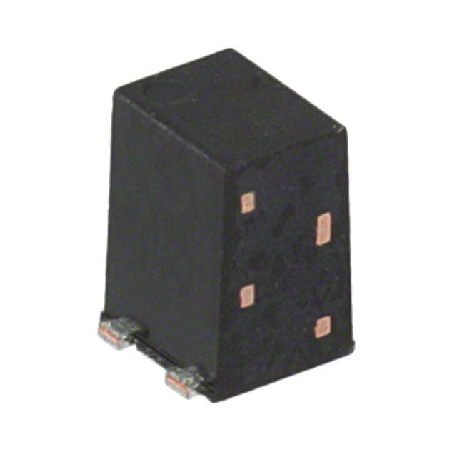
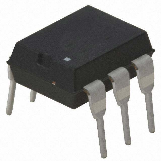
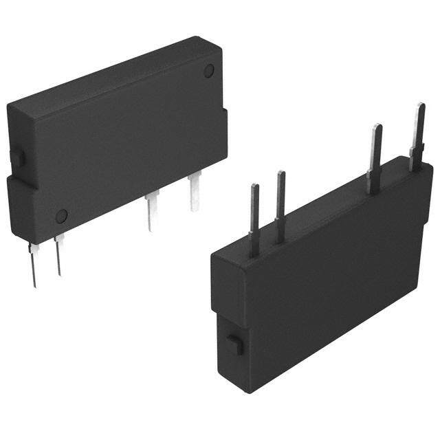
| 描述 | RELAY OPTO 60VAC/DC 1000MA 4-SOP固态继电器-PCB安装 500MA 60V 4PIN SPST 1A |
| 产品分类 | |
| 品牌 | Panasonic Electric Works |
| 产品手册 | |
| 产品图片 |
|
| rohs | RoHS 合规性豁免无铅 / 符合限制有害物质指令(RoHS)规范要求 |
| 产品系列 | 固态继电器,固态继电器-PCB安装,Panasonic Industrial Devices AQY212GSPhotoMOS™ AQY |
| 数据手册 | |
| 产品型号 | AQY212GS |
| 产品 | Telecommunication Relays |
| 产品培训模块 | http://www.digikey.cn/PTM/IndividualPTM.page?site=cn&lang=zhs&ptm=15800 |
| 产品目录绘图 |
|
| 产品目录页面 | |
| 产品种类 | 固态继电器-PCB安装 |
| 产品类型 | PCB Mount |
| 供应商器件封装 | 4-SOP |
| 其它名称 | 255-1792 |
| 其它有关文件 | |
| 包装 | 管件 |
| 商标 | Panasonic Industrial Devices |
| 安装类型 | 表面贴装 |
| 安装风格 | SMD/SMT |
| 导通电阻 | 700 毫欧 |
| 导通电阻—最大值 | 340 mOhms |
| 封装 | Tube |
| 封装/外壳 | 4-SOP(0.173",4.40mm) |
| 封装/箱体 | SOP-4 |
| 工厂包装数量 | 100 |
| 应用说明 | |
| 控制电压范围 | 1.5 V to 5 V |
| 最大工作温度 | + 85 C |
| 最小工作温度 | - 40 C |
| 标准包装 | 100 |
| 特色产品 | http://www.digikey.com/cn/zh/ph/Panasonic/PhotoMOS.html |
| 电压-负载 | 0 ~ 60 V |
| 电压-输入 | 1.14VDC |
| 电路 | SPST-NO(1 A 形) |
| 端子类型 | 鸥翼型 |
| 端接类型 | Gull Wing Lead |
| 继电器类型 | |
| 触点形式 | SPST (1 Form A) |
| 设计资源 | |
| 负载电压额定值 | 60 V |
| 负载电流 | 1A |
| 负载电流额定值 | 1 A |
| 输入电流 | 50 mA |
| 输入转输出绝缘方法 | Optocoupler |
| 输出类型 | AC,DC |
| 输出设备 | MOSFET |


- 商务部:美国ITC正式对集成电路等产品启动337调查
- 曝三星4nm工艺存在良率问题 高通将骁龙8 Gen1或转产台积电
- 太阳诱电将投资9.5亿元在常州建新厂生产MLCC 预计2023年完工
- 英特尔发布欧洲新工厂建设计划 深化IDM 2.0 战略
- 台积电先进制程称霸业界 有大客户加持明年业绩稳了
- 达到5530亿美元!SIA预计今年全球半导体销售额将创下新高
- 英特尔拟将自动驾驶子公司Mobileye上市 估值或超500亿美元
- 三星加码芯片和SET,合并消费电子和移动部门,撤换高东真等 CEO
- 三星电子宣布重大人事变动 还合并消费电子和移动部门
- 海关总署:前11个月进口集成电路产品价值2.52万亿元 增长14.8%


PDF Datasheet 数据手册内容提取
Miniature SOP4-pin type with high capacity GU SOP 1 Form A High Capacity up to 1.6A (AQY21❍GS) FEATURES TYPICAL APPLICATIONS 4.3 4.4 1. Continuous load current: Max. 1.6A • Measuring instruments .169 .173 2.1 high capacity (AQY211G2S) Tester, etc. .083 2. Low on resistance: Typ. 0.1 Ω • Security and disaster-preventing mm inch (AQY211G2S) system 3. Broad lineup of high capacity types Use in I/O for alarm and security devices, 1 4 etc. 2 3 RoHS compliant TYPES Output rating* Part No. Packing quantity Tape and reel packing style Load Load Package voltage current Tube packing style Picked from the Picked from the Tube Tape and reel 1/2-pin side 3/4-pin side 40V 1.6A AQY211G2S AQY211G2SX AQY211G2SZ 1 tube contains: AC/DC 100 pcs. 1.25A SOP4-pin AQY212G2S AQY212G2SX AQY212G2SZ 1,000 pcs. dual use 60V 1 batch contains: 1.0A AQY212GS AQY212GSX AQY212GSZ 2,000 pcs. * Indicate the peak AC and DC values. Note:For space reasons, the three initial letters of the part number “AQY”, the surface mount terminal shape indicator “S” and the packing style indicator “X” or “Z” are not marked on the device. (Ex. the label for product number AQY212G2SX is 212G2.) RATING 1. Absolute maximum ratings (Ambient temperature: 25°C 77°F) Item Symbol AQY211G2S AQY212G2S AQY212GS Remarks LED forward current IF 50 mA LED reverse voltage VR 5 V Input Peak forward current IFP 1 A f = 100 Hz, Duty factor = 0.1% Power dissipation Pin 75 mW Load voltage (peak AC) VL 40 V 60 V Continuous load current IL 1.6 A 1.25 A 1.0 A Peak AC, DC Output Peak load current Ipeak 4 A 3 A 100ms (1 shot), VL = DC Power dissipation Pout 400 mW Total power dissipation PT 450 mW I/O isolation voltage Viso 1,500 Vrms Ambient Operating Topr –40 to +85°C –40 to +185°F (Non-icing at low temperatures) temperature Storage Tstg –40 to +100°C –40 to +212°F –1– ASCTB133E 201703-T
GU SOP 1 Form A High Capacity (AQY21❍GS) 2. Electrical characteristics (Ambient temperature: 25°C 77°F) Item Symbol AQY211G2S AQY212G2S AQY212GS Condition Typical 0.9 mA 1.1 mA LED operate current IFon IL = 100mA Maximum 3 mA Minimum 0.2 mA 0.3 mA Input LED turn off current IFoff IL = 100mA Typical 0.8 mA 1.0 mA Typical 1.32 V (1.14 V at IF = 5 mA) LED dropout voltage VF IF = 50 mA Maximum 1.5 V Typical 0.1 Ω 0.2 Ω 0.34 Ω IF = 5 mA Output On resistance Maximum Ron 0.15 Ω 0.5 Ω 0.7 Ω IWL =ith Mina 1x .s Off state leakage current Maximum ILeak 1 μA IVF L= = 0 M maAx. Typical 1.0 ms 1.3 ms IF = 5 mA Turn on time* Ton IL = 100 mA Maximum 3.0 ms 5.0 ms VL = 10 V Typical 0.12 ms 0.1 ms IF = 5 mA Turn off time* Toff IL = 100 mA Maximum 0.5 ms VL = 10 V Transfer Typical 0.8 pF f = 1 MHz characteristics I/O capacitance Maximum Ciso 1.5 pF VB = 0 V Initial I/O isolation resistance Minimum Riso 1,000 MΩ 500 V DC IF = 5 mA duty = 50% Max. operating frequency Maximum — 10 cps 5 cps — VL = Max. IL = Max. *Turn on/Turn off time Input 90% Output 10% 3. Recommended operating conditions (Ambient temperature: 25°C 77°F) Ton Toff Please use under recommended operating conditions to obtain expected characteristics. Item Symbol Min. Max. Unit LED current IF 5 30 mA Load voltage (Peak AC) VL — 32 V AQY211G2S Continuous load current IL — 1.6 A Load voltage (Peak AC) VL — 48 V AQY212G2S Continuous load current IL — 1.25 A Load voltage (Peak AC) VL — 48 V AQY212GS Continuous load current IL — 1.0 A ■ These products are not designed for automotive use. If you are considering to use these products for automotive applications, please contact your local Panasonic Corporation technical representative. REFERENCE DATA 1. Load current vs. ambient temperature 2. On resistance vs. ambient temperature 3. Turn on time vs. ambient temperature characteristics characteristics characteristics Allowable ambient temperature:–40 to +85°C Measured portion: between terminals 3 and 4; LED current: 5 mA; Load voltage: 10 V (DC); –40 to +185°F LED current: 5 mA; Load voltage: Max. (DC) Continuous load current: 100 mA (DC) Continuous load current: Max.(DC) 2.0 1 5 AQY211G2S 0.8 4 Load current, A11..50 AAQQYY221122GGS2S ΩOn resistance, 00..64 AQY212GS Turn on time, ms 23 AQY212GS, AQY212G2S 0.5 AQY212G2S 0.2 1 AQY211G2S AQY211G2S 0 0 0 -40 -20 0 20 40 60 8085 100 -40 -20 0 20 40 60 8085 –40 –20 0 20 40 60 8085 Ambient temperature, °C Ambient temperature, °C Ambient temperature, °C –2– ASCTB133E 201703-T
GU SOP 1 Form A High Capacity (AQY21❍GS) 4. Turn off time vs. ambient temperature 5. LED operate current vs. ambient 6. LED turn off current vs. ambient temperature characteristics temperature characteristics characteristics LED current: 5 mA; Load voltage: 10 V (DC); Load voltage: 10 V (DC); Load voltage: 10 V (DC); Continuous load current: 100 mA (DC) Continuous load current: 100mA (DC) Continuous load current: 100mA (DC) 1 5 5 A A Turn off time, ms000...486 D operate current, m 234 D turn off current, m 234 LE AQY212GS, AQY212G2S LE AQY212GS, AQY212G2S 0.2 AQY212GS, AQY212G2S 1 1 AQY211G2S AQY211G2S AQY211G2S 0 0 0 –40 –20 0 20 40 60 8085 –40 –20 0 20 40 60 8085 –40 –20 0 20 40 60 8085 Ambient temperature, °C Ambient temperature, °C Ambient temperature, °C 7. LED dropout voltage vs. ambient 8. Current vs. voltage characteristics of output 9. Off state leakage current vs. load voltage temperature characteristics at MOS portion characteristics LED current: 5 to 50 mA Measured portion: between terminals 3 and 4; Measured portion: between terminals 3 and 4; Ambient temperature: 25°C 77°F Ambient temperature: 25°C 77°F 1.5 2 AQY211G2S A10-4 dropout voltage, V11..34 50mA -0.6 -0.4 -0.2Current, A 1 0 0.2AAQQYY2021.4122GG2SS0.6 e leakage current, 1100--86 LED 1.2 3200mmAA Voltage, V Off stat10-10 AQY212GS, AQY212G2S 1.1 10mA -1 AQY211G2S 5mA 10-12 1 -2 –40 –20 0 20 40 60 8085 0 10 20 30 40 50 60 Ambient temperature, °C Load voltage, V 10. Turn on time vs. LED forward current 11. Turn off time vs. LED forward current 12. Output capacitance vs. applied voltage characteristics characteristics characteristics Measured portion: between terminals 3 and 4; Measured portion: between terminals 3 and 4; Measured portion: between terminals 3 and 4; Load voltage: 10 V (DC); Load voltage: 10 V (DC); Frequency: 1 MHz; Continuous load current: 100 mA (DC); Continuous load current: 100 mA (DC); Ambient temperature: 25°C 77°F Ambient temperature: 25°C 77°F Ambient temperature: 25°C 77°F 5 0.5 500 F Turn on time, ms 234 AQY211G2S Turn off time, ms000...243 utput capacitance, p243000000 O AQY212GS, AQY212G2S AQY212GS 1 0.1 100 AQY212GS, AQY212G2S AQY211G2S AQY211G2S AQY212G2S 0 0 0 0 10 20 30 40 50 0 10 20 30 40 50 0 10 20 30 40 50 60 LED forward current, mA LED forward current, mA Applied voltage, V 13. Max. operating frequency vs. load voltage and load current LED current: 5 mA Ambient temperature: 25°C 77°F 50 duty=50% ps ncy, c 40 e u q e g fr 30 n ati per 20 o ax. AQY211G2S M 10 AQY212G2S 0 0 25 50 75 100 Load voltage, V × Load current, A –3– ASCTB133E 201703-T
None
Mouser Electronics Authorized Distributor Click to View Pricing, Inventory, Delivery & Lifecycle Information: P anasonic: AQY212GS AQY212G2SX AQY212G2SZ