ICGOO在线商城 > 射频/IF 和 RFID > RF 天线 > ANT-433-PW-QW
 Datasheet下载
- 型号: ANT-433-PW-QW
- 制造商: LINX TECHNOLOGIES
- 库位|库存: xxxx|xxxx
- 要求:
| 数量阶梯 | 香港交货 | 国内含税 |
| +xxxx | $xxxx | ¥xxxx |
查看当月历史价格
查看今年历史价格
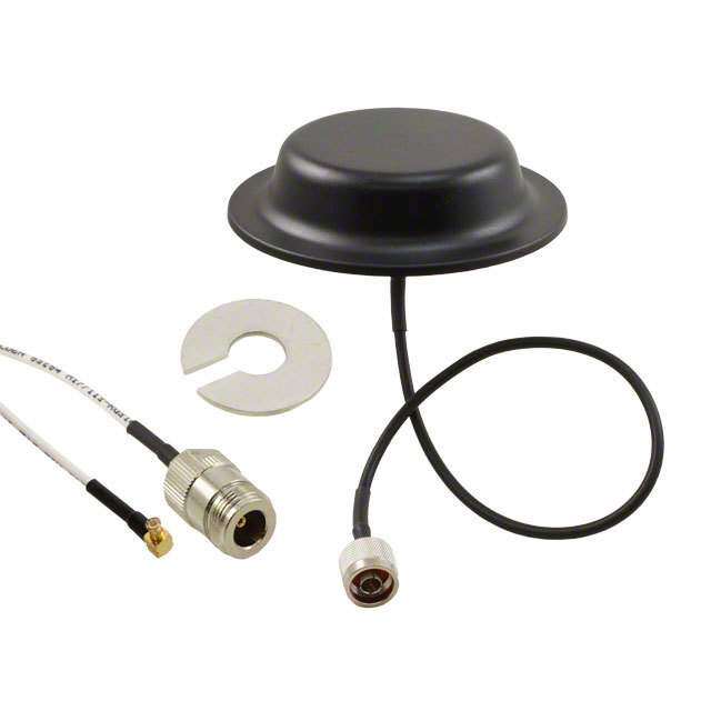
ANT-433-PW-QW产品简介:
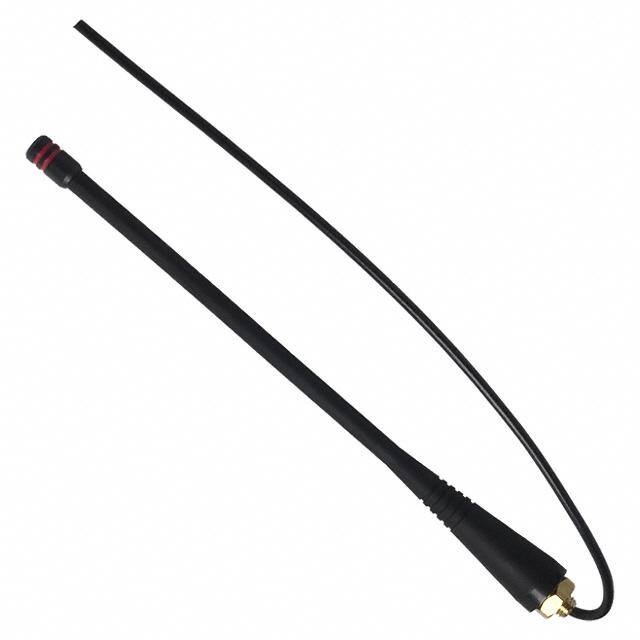
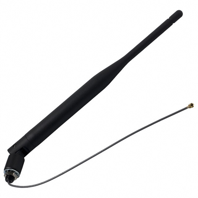
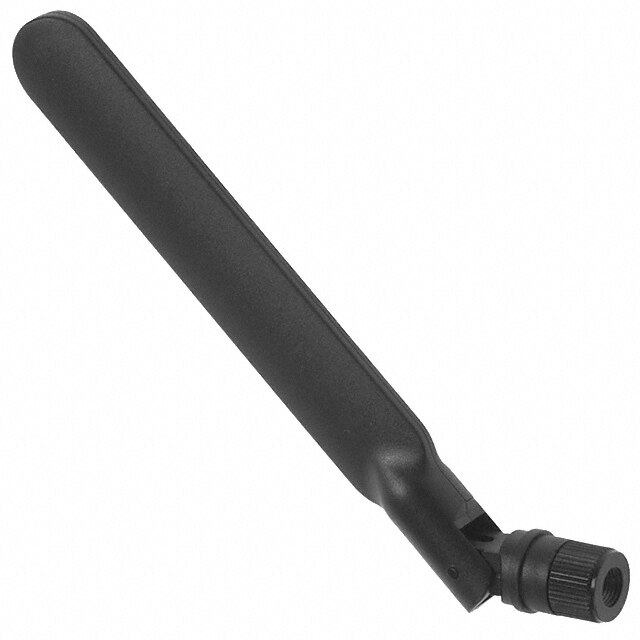
ICGOO电子元器件商城为您提供ANT-433-PW-QW由LINX TECHNOLOGIES设计生产,在icgoo商城现货销售,并且可以通过原厂、代理商等渠道进行代购。 ANT-433-PW-QW价格参考。LINX TECHNOLOGIESANT-433-PW-QW封装/规格:RF 天线, 433MHz Alarms, ISM, Remote Control, Security Systems Whip, Straight RF Antenna 400MHz ~ 470MHz 3.3dBi Solder Panel Mount。您可以下载ANT-433-PW-QW参考资料、Datasheet数据手册功能说明书,资料中有ANT-433-PW-QW 详细功能的应用电路图电压和使用方法及教程。
Linx Technologies Inc. 的 ANT-433-PW-QW 是一款专为 433 MHz 频段设计的射频(RF)天线,属于其小型化、高性能天线产品线。该天线通常用于短距离无线通信系统,适用于工业、住宅和商业环境中的低功耗无线应用。

主要应用场景包括:无线传感器网络、远程监控系统、家庭自动化设备(如无线门铃、智能照明控制)、安防系统(如门窗传感器、报警器)、遥测设备以及工业遥控装置。由于其工作频率为 433 MHz,该频段在许多国家允许免许可使用,适合无需高速数据传输但要求稳定、远距离通信的场合。

ANT-433-PW-QW 具有高效率、全向辐射模式和紧凑结构,便于集成到空间受限的设备中。它常与 Linx 的 UHF 发射模块(如 LC/LA 系列)配合使用,实现可靠的点对点或一对多无线连接。此外,该天线适用于电池供电设备,有助于延长设备续航时间。

总体而言,ANT-433-PW-QW 广泛应用于需要稳定、低功耗、中距离无线通信的物联网(IoT)终端设备和嵌入式系统中,尤其适合在复杂电磁环境中保持良好信号穿透能力的场景。
| 参数 | 数值 |
| 产品目录 | |
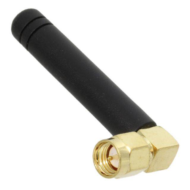
| 描述 | ANTEN 433MHZ PRMNT 1/4 WAVE WHIP天线 Permanent Mount 1/4 Wave Whip 433MHz |
| 产品分类 | |
| 品牌 | Linx Technologies Inc |
| 产品手册 | |
| 产品图片 |
|
| rohs | 符合RoHS无铅 / 符合限制有害物质指令(RoHS)规范要求 |
| 产品系列 | Linx Technologies ANT-433-PW-QWPW - Antenna Factor |
| 数据手册 | |
| 产品型号 | ANT-433-PW-QW |
| VSWR | 1.9 |
| 产品目录绘图 |
|
| 产品种类 | 天线 |
| 其它名称 | ANT-433-PW |
| 包装 | 散装 |
| 商标 | Linx Technologies |
| 增益 | - |
| 天线类型 | 鞭状 |
| 安装类型 | 底座安装 |
| 安装风格 | Through-Hole |
| 封装 | Tray |
| 尺寸 | 6.81 in H |
| 工厂包装数量 | 24 |
| 带宽 | 80 MHz |
| 技术类型 | 1/4 Wave Whip Antenna |
| 标准包装 | 24 |
| 电缆长度 | 8.5 in |
| 端接 | QSL |
| 系列 | QW |
| 阻抗 | 50 Ohms |
| 频带数 | 1 |
| 频率 | 433MHz(393MHz ~ 473MHz) |
| 高度 | 6.81 in |
| 高度(最大值) | 6.811" (173.00mm) |


PDF Datasheet 数据手册内容提取
ANT-433-PW-QW-xxx Data Sheet by Product Description 7.8 mm Designed for permanent attachment, PW Series (0.31") ¼-wave whips give outstanding performance in a rugged and cost-effective package. The antenna 13.0 mm is attached by placing its base through a ¼" (6.35 (0.51") mm) hole in the product and securing it with a nut or by threading it into a PEM-style insert. The antenna is fed through the base with 8.5" (216 6.0 mm mm) of coax cable. Straight-cut RG-174 allows the (0.24") addition of any 50-ohm RF connector or allows the 173.0 mm Straight Cut or U.FL cable to be soldered directly to the PCB, saving (6.81") the cost of the connector. It is also available with 1.32 mm coax cable terminated with a U.FL / I-PEX silhouette MHF compatible connector. This saves the labor shown in shadow of adding a connector while using one that is small enough to fit through the antenna’s mounting hole. Custom lengths and terminations are available by special order. Features • Low cost 52.0 mm • Outstanding performance (2.05") • Omni-directional pattern 4.5 mm (0.18") • Wide bandwidth • Flexible main shaft 1/4-28 • Rugged & weatherized UNF • Integral 8.5" (216 mm) RG-174 coax cable or 1.32 mm coax (U.FL) 216 mm • Use with plastic* or metal enclosures (8.5") * Requires proximity ground plane 7/16" HEX 14.5 mm Electrical Specifications (0.57") Center Frequency: 433MHz End View Bandwidth: 400–470MHz Wavelength: ¼-wave Ordering Information VSWR: ≤ 1.9 typical at center ANT-433-PW-QW (with straight cut RG-174 coax) Peak Gain: 3.3dBi ANT-433-PW-QW-UFL (U.FL/MHF compatible Impedance: 50-ohms connector) Connection: Straight-cut or U.FL/MHF Cable: 8.5” (216 mm) RG-174 coax cable or 1.32 mm coax (U.FL) Oper. Temp. Range: –40°C to +90°C Electrical specifications and plots measured on 10.16 cm x 10.16 cm (4.00" x 4.00") reference ground plane – 1 – Revised 1/26/15
Counterpoise Quarter-wave or monopole antennas require an associated ground plane counterpoise for proper operation. The size and location of the ground plane relative to the antenna will affect the overall performance of the antenna in the final design. When used in conjunction with a ground plane smaller than that used to tune the antenna, the center frequency typically will shift higher in frequency and the bandwidth will decrease. The proximity of other circuit elements and packaging near the antenna will also affect the final performance. For further discussion and guidance on the importance of the ground plane counterpoise, please refer to Linx Application Note AN-00501: Understanding Antenna Specifications and Operation. VSWR Graph VSWR 1.095 Reflected Power 3:1 25% 2:1 11% 1:1 0% 333.92MHz 433.92MHz 533.92MHz What is VSWR? The Voltage Standing Wave Ratio (VSWR) is a measurement of how well an antenna is matched to a source impedance, typically 50-ohms. It is calculated by measuring the voltage wave that is headed toward the load versus the voltage wave that is reflected back from the load. A perfect match will have a VSWR of 1:1. The higher the first number, the worse the match, and the more inefficient the system. Since a perfect match cannot ever be obtained, some benchmark for performance needs to be set. In the case of antenna VSWR, this is usually 2:1. At this point, 88.9% of the energy sent to the antenna by the transmitter is radiated into free space and 11.1% is either reflected back into the source or lost as heat on the structure of the antenna. In the other direction, 88.9% of the energy recovered by the antenna is transferred into the receiver. As a side note, since the “:1” is always implied, many data sheets will remove it and just display the first number. How to Read a VSWR Graph VSWR is usually displayed graphically versus frequency. The lowest point on the graph is the antenna’s operational center frequency. In most cases, this will be different than the designed center frequency due to fabrication tolerances. The VSWR at that point denotes how close to 50-ohms the antenna gets. Linx specifies the recommended bandwidth as the range where the typical antenna VSWR is less than 2:1. – 2 – Data Sheet ANT-433-PW-QW-xxx by