 Datasheet下载
- 型号: ALC10C152EG250
- 制造商: Kemet
- 库位|库存: xxxx|xxxx
- 要求:
| 数量阶梯 | 香港交货 | 国内含税 |
| +xxxx | $xxxx | ¥xxxx |
查看当月历史价格
查看今年历史价格
ALC10C152EG250产品简介:
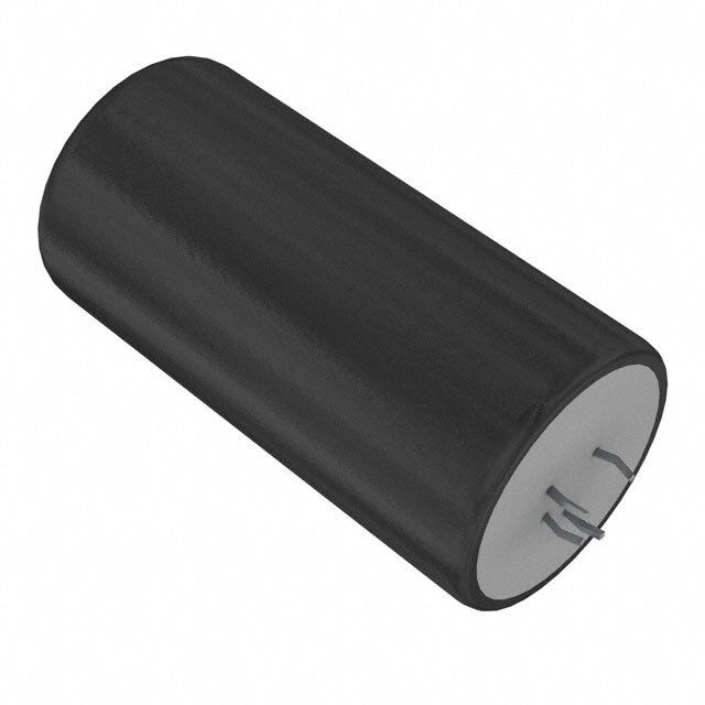
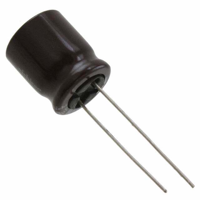
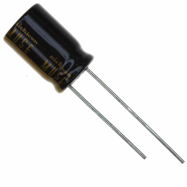
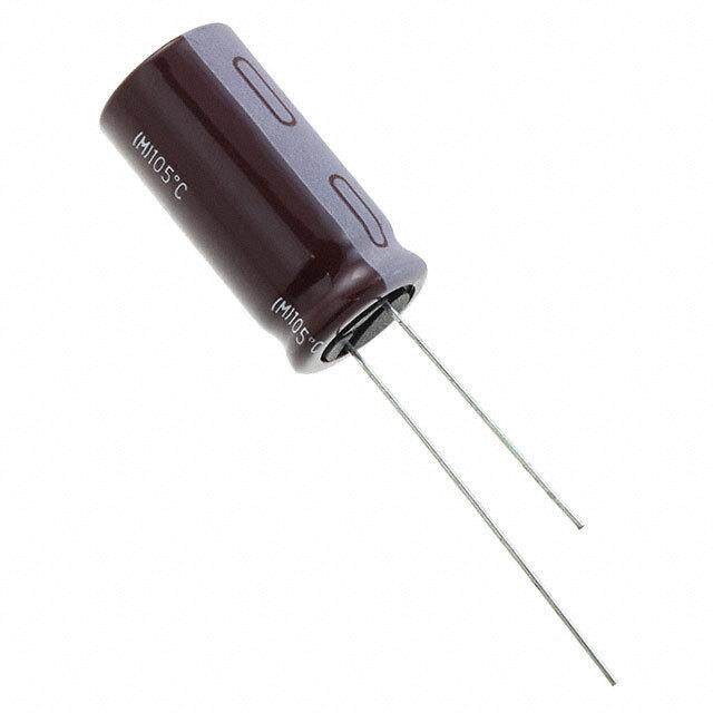
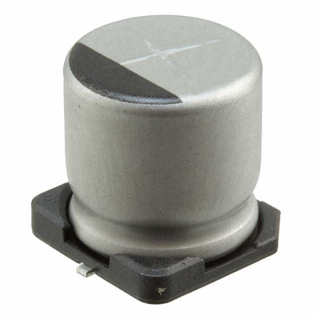
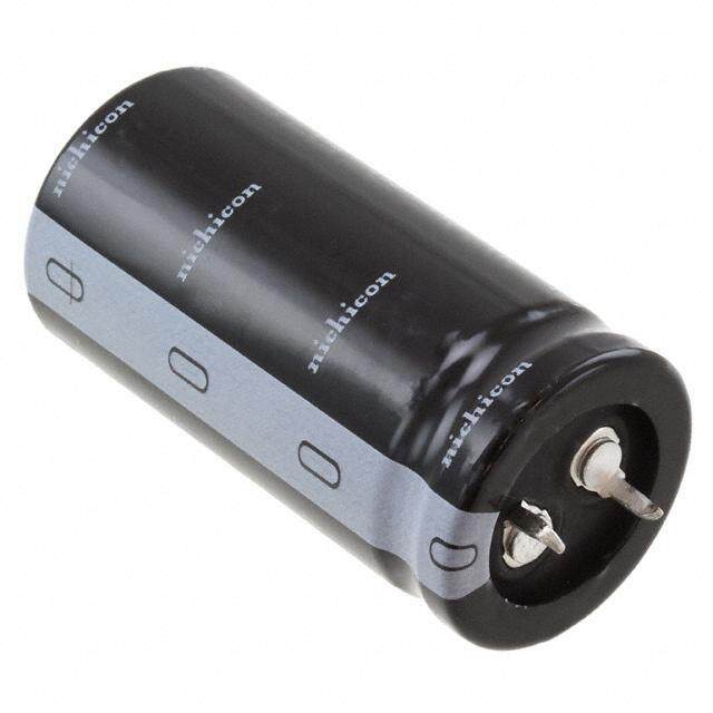
ICGOO电子元器件商城为您提供ALC10C152EG250由Kemet设计生产,在icgoo商城现货销售,并且可以通过原厂、代理商等渠道进行代购。 ALC10C152EG250价格参考¥91.86-¥91.86。KemetALC10C152EG250封装/规格:铝电解电容器, 1500µF 250V 铝电解电容器 径向,罐 - 卡入式 - 4 引线 89 毫欧 @ 100Hz 85°C 时为 2000 小时。您可以下载ALC10C152EG250参考资料、Datasheet数据手册功能说明书,资料中有ALC10C152EG250 详细功能的应用电路图电压和使用方法及教程。
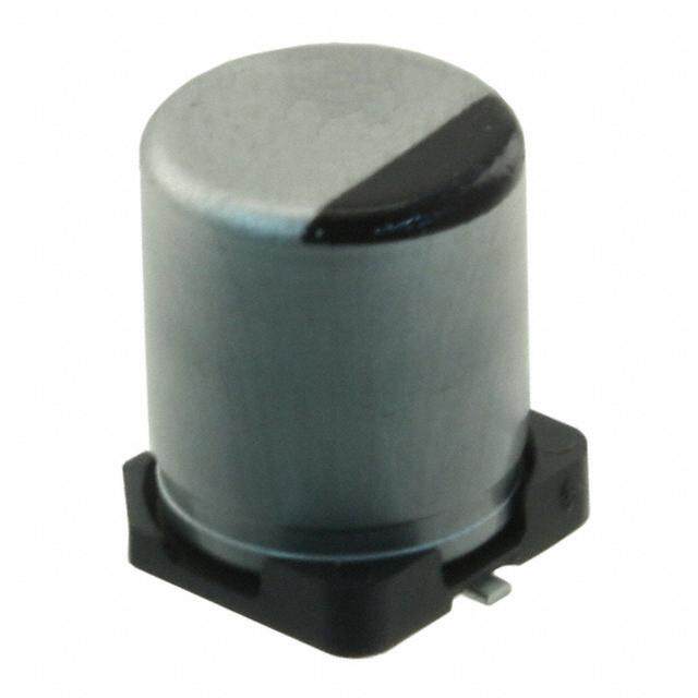
KEMET品牌的ALC10C152EG250是一款铝电解电容器,常见应用于需要稳定电源滤波和能量存储的电子设备中。该型号电容的额定电压为25V,电容值为1500μF(微法),适用于多种工业和消费类电子产品。

其主要应用场景包括:

1. 电源供应器:用于开关电源、DC-DC转换器等,作为输入/输出滤波电容,稳定电压,减少纹波。

2. 工业控制设备:如PLC(可编程逻辑控制器)、变频器、伺服驱动器等,用于电源平滑和噪声抑制。

3. 消费类电子产品:如音响设备、电视机、机顶盒等,用于电源部分的滤波,提升设备运行稳定性。

4. 照明系统:LED驱动电源中用于滤波和能量存储,确保光源稳定。

5. 汽车电子系统:在车载音响、导航系统或辅助驾驶模块中,提供稳定的电源支持。

该电容器具有较高的可靠性和较长的使用寿命,适合在中等温度环境下长期工作。其封装形式为径向引线式,便于安装于PCB电路板上,广泛应用于各类中高功率电子系统中。
| 参数 | 数值 |
| 产品目录 | |
| 描述 | CAP ALUM 1500UF 250V 20% SNAP铝质电解电容器-管理单元 250volts 1500uF 20% |
| ESR(等效串联电阻) | 89 毫欧 |
| 产品分类 | |
| 品牌 | Kemet |
| 产品手册 | http://www.kemet.com/docfinder?Partnumber=ALC10C152EG250 |
| 产品图片 |
|
| rohs | 符合RoHS无铅 / 符合限制有害物质指令(RoHS)规范要求 |
| 产品系列 | 铝电解电容器,铝质电解电容器-管理单元,Kemet ALC10C152EG250Evox Rifa ALC10 |
| 数据手册 | |
| 产品型号 | ALC10C152EG250 |
| 不同温度时的使用寿命 | 85°C 时为 18000 小时 |
| 产品 | Aluminum Electrolytic Capacitors |
| 产品培训模块 | http://www.digikey.cn/PTM/IndividualPTM.page?site=cn&lang=zhs&ptm=25569http://www.digikey.cn/PTM/IndividualPTM.page?site=cn&lang=zhs&ptm=26047 |
| 产品目录绘图 |
|
| 产品目录页面 | |
| 产品种类 | 铝质电解电容器-管理单元 |
| 其它名称 | 399-5661 |
| 加载寿命 | 18000 h |
| 包装 | 散装 |
| 商标 | Kemet |
| 大小/尺寸 | 1.575" 直径(40.00mm) |
| 安装类型 | 通孔 |
| 容差 | ±20% |
| 封装 | Bulk |
| 封装/外壳 | 径向,罐 - 卡入式 - 4 引线 |
| 工作温度 | -40°C ~ 85°C |
| 工厂包装数量 | 36 |
| 应用 | 通用 |
| 引线间距 | 0.886"(22.50mm) |
| 引线间隔 | 10 mm |
| 最大工作温度 | + 85 C |
| 最小工作温度 | - 40 C |
| 标准包装 | 36 |
| 测试频率 | 100 Hz |
| 漏泄电流 | 6 mA |
| 电压额定值DC | 250 V |
| 电容 | 1500µF |
| 直径 | 40 mm |
| 端接类型 | Snap In |
| 管脚数量 | 4 |
| 类型 | - |
| 系列 | ALC10 |
| 纹波电流 | 5.29A |
| 表面贴装焊盘尺寸 | - |
| 长度 | 55 mm |
| 阻抗 | 69 毫欧 |
| 零件号别名 | A521HJ152M250C |
| 额定电压 | 250V |
| 高度-安装(最大值) | 2.165"(55.00mm) |


- 商务部:美国ITC正式对集成电路等产品启动337调查
- 曝三星4nm工艺存在良率问题 高通将骁龙8 Gen1或转产台积电
- 太阳诱电将投资9.5亿元在常州建新厂生产MLCC 预计2023年完工
- 英特尔发布欧洲新工厂建设计划 深化IDM 2.0 战略
- 台积电先进制程称霸业界 有大客户加持明年业绩稳了
- 达到5530亿美元!SIA预计今年全球半导体销售额将创下新高
- 英特尔拟将自动驾驶子公司Mobileye上市 估值或超500亿美元
- 三星加码芯片和SET,合并消费电子和移动部门,撤换高东真等 CEO
- 三星电子宣布重大人事变动 还合并消费电子和移动部门
- 海关总署:前11个月进口集成电路产品价值2.52万亿元 增长14.8%

PDF Datasheet 数据手册内容提取
Snap-In Aluminum Electrolytic Capacitors ALC10, +85°C Overview Applications The KEMET ALC10 snap-in capacitors covers a wide range The KEMET ALC10 capacitors are ideally suited for of case sizes and voltage ratings. The ALC10 is designed industrial and commercial applications demanding high for high voltage, it is up to 600 VDC, has high ripple current reliability and long life expectancy. Typical applications applications and features surge voltage capability and very include frequency converters, uninterruptible power supply long-life performance. (UPS) systems and switch mode power supplies (SMPS). Benefits • Compact size • Long life, up to 18,000 hours at +85°C (V , I applied) R R • High ripple current • High voltage • Excellent surge voltage capability • Optimized designs available upon request Part Number System ALC10 A 392 BB 040 Series Termination Capacitance Code (µF) Size Code Rated Voltage (VDC) Snap-In See Termination Table First two digits See Dimension Table 035 = 35 350 = 350 Aluminum represent significant 040 = 40 400 = 400 Electrolytic figures. Third digit 063 = 63 450 = 450 specifies number of 100 = 100 500 = 500 zeros. 200 = 200 550 = 550 250 = 250 600 = 600 One world. One KEMET © KEMET Electronics Corporation • KEMET Tower • One East Broward Boulevard A4020_ALC10 • 2/13/2019 1 Fort Lauderdale, FL 33301 USA • 954-766-2800 • www.kemet.com
Snap-In Aluminum Electrolytic Capacitors – ALC10, +85ºC Performance Characteristics Item Performance Characteristics Capacitance Range 47 – 100,000 µF Rated Voltage 35 – 600 VDC Operating Temperature −40 to +85°C Capacitance Tolerance ±20% at 100 Hz/+20°C Rated Voltage and Ripple D (mm) Rated Voltage at +85°C (hours) Current at +85°C (hours) 25 10,000 16,000 Operational Lifetime 30 13,000 21,000 35 15,000 24,000 40 – 50 18,000 29,000 End of Life Requirement ∆ C/C < ±10%, ESR < 2 x initial ESR value, IL < initial specified limit Shelf Life 2,000 hours at +85°C or 30,000 hours at +40°C 0 VDC I = 0.006 CV or 6,000 (µA, whichever is smaller) Leakage Current C = rated capacitance (µF), V = rated voltage (VDC). Voltage applied for 5 minutes at +20°C. Procedure Requirements 0.75 mm displacement amplitude or 10 g maximum acceleration. D ≤ 40 mm Vibration applied for three 2-hour sessions at 10 – 500 Hz No leakage of electrolyte Vibration Test Specifications (capacitor clamped by body). or other visible damage. Deviations in capacitance from 0.35 mm displacement amplitude initial measurements must not or 5 g maximum acceleration. exceed: ∆ C/C < 5% D > 40 mm Vibration applied for three 0.5-hour sessions at 10 – 55 Hz (capacitor clamped by body). Standards IEC 60384–4 long life grade 40/85/56 Surge Voltage Voltage (VDC) Condition 35 40 63 100 200 250 350 400 450 500 550 600 ≤ 30s Surge followed by a no load 40.25 46 72.5 115 230 288 385 440 495 550 605 660 period of 330s, 1,000 cycles at +85°C ≤ 500 ms surge, 100 cycles at 20°C, occurring randomly throughout the 350 400 500 520 550 600 620 670 life of the capacitor © KEMET Electronics Corporation • KEMET Tower • One East Broward Boulevard A4020_ALC10 • 2/13/2019 2 Fort Lauderdale, FL 33301 USA • 954-766-2800 • www.kemet.com
Snap-In Aluminum Electrolytic Capacitors – ALC10, +85ºC Test Method & Performance Endurance Life Test Conditions Performance Temperature +85°C Test Duration 2,000 hours Ripple Current Rated ripple current in specified table Voltage The sum of DC voltage and the peak AC voltage must not exceed the rated voltage of the capacitor Performance The following specifications will be satisfied when the capacitor is tested at +20°C: ≤ 160 V Within 15% of the initial value Capacitance Change ≥ 160 V Within 10% of the initial value Equivalent Series Resistance Does not exceed 200% of the initial value Leakage Current Does not exceed leakage current limit Dimensions – Millimeters Dimensions in mm Approximate Dimensions in mm Approximate Size Code D L Weight Size Code D L Weight Grams Grams −0/+1 ±2 −0/+1 ±2 BB 25 30 28 EH 40 60 98 BC 25 35 30 EJ 40 70 113 BD 25 40 35 EL 40 80 131 CB 30 30 35 EP 40 105 170 CC 30 35 40 FB 45 30 62 CD 30 40 45 FC 45 35 72 CE 30 45 50 FD 45 40 82 CF 30 50 55 FE 45 45 92 DB 35 30 42 FF 45 50 103 DC 35 35 50 FG 45 55 113 DD 35 40 55 FH 45 60 123 DE 35 45 65 FL 45 80 164 DF 35 50 70 FP 45 105 215 DG 35 55 75 KB 50 30 75 DH 35 60 80 KC 50 35 88 DL 35 80 105 KD 50 40 100 EB 40 30 49 KE 50 45 113 EC 40 35 57 KF 50 50 126 ED 40 40 65 KG 50 55 138 EE 40 45 80 KH 50 60 151 EF 40 50 82 KL 50 80 201 EG 40 55 95 KP 50 105 264 Note: Dimensions include sleeving Note: Dimensions include sleeving © KEMET Electronics Corporation • KEMET Tower • One East Broward Boulevard A4020_ALC10 • 2/13/2019 3 Fort Lauderdale, FL 33301 USA • 954-766-2800 • www.kemet.com
Snap-In Aluminum Electrolytic Capacitors – ALC10, +85ºC Termination Tables Termination Code A D F C E G H Diameter (mm) 25 • • • 30 • • • 35 • • • • • 40 • • • • • • • 45 • • • • 50 • • • • Mounting: These capacitors are designed to be mounted by their terminations alone and may be used in any position. Dummy pins must be isolated on 4 and 5 pin styles. Termination Termination LL Code Style ±1 Standard Termination Option A 2 Pin 6.3 G (D ≥ 45) 5 Pin 6.3 Other Termination Options D 2 Pin 4 F 3 Pin 4 C 4 Pin 6.3 E 4 Pin 4 H 5 Pin 4 Dimensions in mm © KEMET Electronics Corporation • KEMET Tower • One East Broward Boulevard A4020_ALC10 • 2/13/2019 4 Fort Lauderdale, FL 33301 USA • 954-766-2800 • www.kemet.com
Snap-In Aluminum Electrolytic Capacitors – ALC10, +85ºC Termination Tables cont'd Style A/D SIDE VIEW TERMINAL PCB LAYOUT END VIEW L D 10 ±0.1 2 ±0.1 LL Style F SIDE VIEW TERMINAL PCB LAYOUT END VIEW Ø2.5 Minimum L + ve 3.3 ±0.1 Ø2 ±0.1 Typical D + - 4.75 ±0.1 10 ±0.1 LL Style C/E SIDE VIEW TERMINAL PCB LAYOUT END VIEW L 4 Holes Ø2 ±0.1 - ve on a Ø22.5 PCD - D 30° 30° + LL + ve Style G/H SIDE VIEW TERMINAL PCB LAYOUT END VIEW L 5 Holes Ø2 ±0.1 - ve on a Ø25.0 PCD - 30° D 30° 30° + LL + ve © KEMET Electronics Corporation • KEMET Tower • One East Broward Boulevard A4020_ALC10 • 2/13/2019 5 Fort Lauderdale, FL 33301 USA • 954-766-2800 • www.kemet.com
Snap-In Aluminum Electrolytic Capacitors – ALC10, +85ºC Shelf Life The capacitance, ESR and impedance of a capacitor will not change significantly after extended storage periods, however, the leakage current will very slowly increase. KEMET products are particularly stable and allow a shelf life in excess of three years at 40°C. See sectional specification under each product for specific data. Re-age (Reforming) Procedure Apply the rated voltage to the capacitor at room temperature for a period of one hour, or until the leakage current has fallen to a steady value below the specified limit. During re-aging, a maximum charging current of twice the specified leakage current or 5 mA (whichever is greater) is suggested. Reliability The reliability of a component can be defined as the probability that it will perform satisfactorily under a given set of conditions for a given length of time. In practice, it is impossible to predict with absolute certainty how any individual component will perform. Therefore, we must utilize probability theory. It is also necessary to clearly define the level of stress involved (e.g., operating voltage, ripple current, temperature and time.) Finally, the meaning of satisfactory performance must be defined by specifying a set of conditions which determine the end of life of the component. Reliability as a function of time, R(t), is normally expressed as: R(t) = e-λt, where R(t) is the probability that the component will perform satisfactorily for time t, and λ is the failure rate. Failure Rate The failure rate is the number of components failing per unit of time. The failure rate of most electronic components follows the characteristic pattern: • Early failures are removed during the manufacturing process. • The operational life is characterized by a constant failure rate. • The wear out period is characterized by a rapidly increasing failure rate. The failures in time (FIT) are given with a 60% confidence level for the various type codes. By convention, FIT is expressed as 1 x 10⁻⁹ failures per hour. Failure rate is also expressed as a percentage of failures per 1,000 hours, e.g., 100 FIT = 1 x 10⁻⁷ failures per hour = 0.01%/1,000 hours. End of Life Definition Catastrophic Failure: short circuit, open circuit or safety vent operation Parametric Failure: • Change in capacitance > ±10% • Leakage current > specified limit • ESR > 2 x initial ESR value © KEMET Electronics Corporation • KEMET Tower • One East Broward Boulevard A4020_ALC10 • 2/13/2019 6 Fort Lauderdale, FL 33301 USA • 954-766-2800 • www.kemet.com
Snap-In Aluminum Electrolytic Capacitors – ALC10, +85ºC MTBF The mean time between failures (MTBF) is simply the inverse of the failure rate. MTBF = 1/λ early failures wear out e at R e ur ail F operational life Time The failure rate is derived from our periodic test results. The failure rate (λ ) is, therefore, only given at test temperature for R life tests. An estimation is also given at 40°C. The expected failure rate for this capacitor range is based on our periodic test results for capacitors with structural similarity. Failure rate is frequently quoted in FIT (Failures In Time) where 1 FIT = 1 x 10⁻⁹ failures per hour. Failure rate per hour includes both catastrophic and parametric failures. T Failure Rate per Hour a 85°C 250 FIT 40°C 12 FIT Environmental Compliance As an environmentally conscious company, KEMET is working continuously with improvements concerning the environmental effects of both our capacitors and their production. In Europe (RoHS Directive) and in some other geographical areas like China, legislation has been put in place to prevent the use of some hazardous materials, such as lead (Pb), in electronic equipment. All products in this catalog are produced to help our customers’ obligations to guarantee their products and fulfill these legislative requirements. The only material of concern in our products has been lead (Pb), which has been removed from all designs to fulfill the requirement of containing less than 0.1% of lead in any homogeneous material. KEMET will closely follow any changes in legislation world wide and make any necessary changes in its products, whenever needed. Some customer segments such as medical, military and automotive electronics may still require the use of lead in electrode coatings. To clarify the situation and distinguish products from each other, a special symbol is used on the packaging labels for RoHS compatible capacitors. Because of customer requirements, there may appear additional markings such as lead-free (LF) or lead-free wires (LFW) on the label. © KEMET Electronics Corporation • KEMET Tower • One East Broward Boulevard A4020_ALC10 • 2/13/2019 7 Fort Lauderdale, FL 33301 USA • 954-766-2800 • www.kemet.com
Snap-In Aluminum Electrolytic Capacitors – ALC10, +85ºC Table 1 – Ratings & Part Number Reference Rated ESR Impedance Case Size Ripple Current VDC Capacitance Size Code Maximum Maximum Part Number 100 Hz 100 Hz 10 kHz 100 Hz 10 kHz D x L (mm) 20°C (µF) 85°C (A) 85°C (A) 20°C (mΩ) 20°C (mΩ) 35 33000 EF 40 x 50 7.16 10.03 42 38 ALC10(1)333EF035 35 56000 EL 40 x 80 11.68 12.92 23 21 ALC10(1)563EL035 35 100000 EP 40 x 105 14.18 15.39 17 16 ALC10(1)104EP035 40 3900 BB 25 x 30 2.33 2.53 125 103 ALC10(1)392BB040 40 4700 BC 25 x 35 2.77 3.01 99 81 ALC10(1)472BC040 40 5600 CB 30 x 30 2.74 2.98 115 94 ALC10(1)562CB040 40 5600 BD 25 x 40 3.14 3.42 85 70 ALC10(1)562BD040 40 6800 CC 30 x 35 3.26 3.55 90 74 ALC10(1)682CC040 40 8200 CD 30 x 40 3.70 4.03 77 63 ALC10(1)822CD040 40 10000 DC 35 x 35 3.69 4.01 86 71 ALC10(1)103DC040 40 12000 CF 30 x 50 4.59 4.99 59 48 ALC10(1)123CF040 40 12000 DD 35 x 40 4.14 4.50 75 62 ALC10(1)123DD040 40 15000 EB 40 x 30 4.42 4.51 89 79 ALC10(1)153EB040 40 18000 DF 35 x 50 5.23 5.69 55 45 ALC10(1)183DF040 40 18000 EC 40 x 35 4.88 4.97 78 70 ALC10(1)183EC040 40 22000 ED 40 x 40 5.81 5.92 62 56 ALC10(1)223ED040 40 27000 EF 40 x 50 7.23 7.36 43 38 ALC10(1)273EF040 40 33000 EH 40 x 60 8.74 8.91 33 30 ALC10(1)333EH040 40 47000 EL 40 x 80 10.96 11.17 23 21 ALC10(1)473EL040 40 82000 EP 40 x 105 12.63 13.44 18 17 ALC10(1)823EP040 63 2200 BB 25 x 30 2.13 2.37 149 118 ALC10(1)222BB063 63 2700 BC 25 x 35 2.43 2.70 128 101 ALC10(1)272BC063 63 3300 CB 30 x 30 2.77 3.08 112 88 ALC10(1)332CB063 63 3300 BD 25 x 40 2.73 3.04 112 88 ALC10(1)332BD063 63 4700 CC 30 x 35 3.24 3.61 91 72 ALC10(1)472CC063 63 5600 CD 30 x 40 3.56 3.96 83 66 ALC10(1)562CD063 63 6800 DC 35 x 35 3.95 4.40 75 59 ALC10(1)682DC063 63 6800 CF 30 x 50 4.07 4.53 75 59 ALC10(1)682CF063 63 8200 DD 35 x 40 4.31 4.80 69 55 ALC10(1)822DD063 63 8200 EB 40 x 30 3.95 4.03 82 72 ALC10(1)822EB063 63 10000 DF 35 x 50 4.85 5.40 64 51 ALC10(1)103DF063 63 10000 EC 40 x 35 4.58 4.67 80 72 ALC10(1)103EC063 63 12000 ED 40 x 40 5.42 5.55 64 57 ALC10(1)123ED063 63 15000 EF 40 x 50 7.02 7.18 44 39 ALC10(1)153EF063 63 18000 EH 40 x 60 8.54 8.75 35 31 ALC10(1)183EH063 63 27000 EL 40 x 80 10.53 10.78 24 21 ALC10(1)273EL063 63 39000 EP 40 x 105 12.23 13.51 19 17 ALC10(1)393EP063 100 1000 BB 25 x 30 1.67 2.04 243 182 ALC10(1)102BB100 100 1200 BC 25 x 35 1.93 2.36 203 152 ALC10(1)122BC100 100 1500 CB 30 x 30 2.30 2.81 163 122 ALC10(1)152CB100 100 1500 BD 25 x 40 2.27 2.78 163 122 ALC10(1)152BD100 100 1800 CC 30 x 35 2.64 3.23 137 103 ALC10(1)182CC100 100 2200 CD 30 x 40 3.05 3.73 113 85 ALC10(1)222CD100 100 2700 DC 35 x 35 3.57 4.37 92 69 ALC10(1)272DC100 100 2700 EB 40 x 30 3.72 3.88 121 104 ALC10(1)272EB100 100 3300 CF 30 x 50 4.05 4.95 76 57 ALC10(1)332CF100 100 3300 DD 35 x 40 4.11 5.03 76 57 ALC10(1)332DD100 100 3300 EC 40 x 35 4.09 4.24 106 92 ALC10(1)332EC100 100 3900 ED 40 x 40 4.88 5.08 85 74 ALC10(1)392ED100 100 4700 DF 35 x 50 5.23 6.40 55 41 ALC10(1)472DF100 100 4700 EE 40 x 45 5.60 5.83 70 61 ALC10(1)472EE100 100 5600 EF 40 x 50 6.41 6.68 59 51 ALC10(1)562EF100 100 6800 EG 40 x 55 6.61 6.84 53 46 ALC10(1)682EG100 100 8200 EH 40 x 60 7.36 7.61 44 39 ALC10(1)822EH100 100 12000 EL 40 x 80 9.14 9.45 31 27 ALC10(1)123EL100 100 18000 EP 40 x 105 11.34 12.61 19 17 ALC10(1)183EP100 200 330 BB 25 x 30 1.18 1.63 486 340 ALC10(1)331BB200 200 390 BC 25 x 35 1.36 1.87 412 288 ALC10(1)391BC200 200 470 CB 30 x 30 1.58 2.18 343 240 ALC10(1)471CB200 200 470 BD 25 x 40 1.56 2.15 343 240 ALC10(1)471BD200 VDC Rated Capacitance Size Code Case Size Ripple Current ESR Impedance Part Number (1) Termination code: See Termination Tables for available options. © KEMET Electronics Corporation • KEMET Tower • One East Broward Boulevard A4020_ALC10 • 2/13/2019 8 Fort Lauderdale, FL 33301 USA • 954-766-2800 • www.kemet.com
Snap-In Aluminum Electrolytic Capacitors – ALC10, +85ºC Table 1 – Ratings & Part Number Reference cont'd Rated ESR Impedance Case Size Ripple Current VDC Capacitance Size Code Maximum Maximum Part Number 100 Hz 100 Hz 10 kHz 100 Hz 10 kHz D x L (mm) 20°C (µF) 85°C (A) 85°C (A) 20°C (mΩ) 20°C (mΩ) 200 560 CC 30 x 35 1.82 2.51 288 202 ALC10(1)561CC200 200 680 CD 30 x 40 2.10 2.89 238 167 ALC10(1)681CD200 200 820 DC 35 x 35 2.43 3.35 198 139 ALC10(1)821DC200 200 820 EB 40 x 30 3.06 3.63 178 142 ALC10(1)821EB200 200 1000 CF 30 x 50 2.76 3.80 163 114 ALC10(1)102CF200 200 1000 DD 35 x 40 2.81 3.87 163 114 ALC10(1)102DD200 200 1000 EC 40 x 35 3.43 3.99 153 124 ALC10(1)102EC200 200 1200 DF 35 x 50 3.06 4.01 135 82 ALC10(1)122DF200 200 1200 ED 40 x 40 4.02 4.69 124 99 ALC10(1)122ED200 200 1500 DF 35 x 50 3.70 5.10 110 77 ALC10(1)152DF200 200 1500 EE 40 x 45 4.61 5.38 101 81 ALC10(1)152EE200 200 1800 EF 40 x 50 5.27 6.15 84 68 ALC10(1)182EF200 200 2200 EH 40 x 60 6.29 7.43 67 53 ALC10(1)222EH200 200 3300 EL 40 x 80 7.83 9.17 46 37 ALC10(1)332EL200 200 4700 EP 40 x 105 8.08 11.73 45 32 ALC10(1)472EP200 200 5600 FP 45 x 105 8.51 12.16 42 29 ALC10(1)562FP200 200 8200 KP 50 x 105 9.17 11.76 33 25 ALC10(1)822KP200 250 220 BB 25 x 30 0.97 1.41 727 473 ALC10(1)221BB250 250 270 BC 25 x 35 1.13 1.65 593 385 ALC10(1)271BC250 250 330 CB 30 x 30 1.33 1.94 486 316 ALC10(1)331CB250 250 330 BC 25 x 35 1.34 1.95 490 320 ALC10(1)331BC250 250 330 BD 25 x 40 1.31 1.91 486 316 ALC10(1)331BD250 250 470 CC 30 x 35 1.67 2.43 343 223 ALC10(1)471CC250 250 560 CD 30 x 40 1.91 2.78 288 187 ALC10(1)561CD250 250 680 DC 35 x 35 2.22 3.23 238 155 ALC10(1)681DC250 250 680 CF 30 x 50 2.29 3.34 238 155 ALC10(1)681CF250 250 680 EB 40 x 30 2.79 3.56 187 144 ALC10(1)681EB250 250 820 DD 35 x 40 2.55 3.72 198 129 ALC10(1)821DD250 250 820 ED 40 x 40 3.80 4.91 153 116 ALC10(1)821ED250 250 1000 DF 35 x 50 3.26 4.75 163 106 ALC10(1)102DF250 250 1000 EE 40 x 45 4.33 5.58 126 96 ALC10(1)102EE250 250 1200 DH 35 x 60 3.76 5.48 140 100 ALC10(1)122DH250 250 1200 EF 40 x 50 4.94 6.37 104 80 ALC10(1)122EF250 250 1500 EG 40 x 55 5.29 6.58 89 69 ALC10(1)152EG250 250 1800 DL 35 x 80 4.60 6.69 100 82 ALC10(1)182DL250 250 1800 EH 40 x 60 5.92 7.34 74 58 ALC10(1)182EH250 250 2200 EL 40 x 80 7.33 9.49 57 43 ALC10(1)222EL250 250 3900 EP 40 x 105 7.78 11.71 46 32 ALC10(1)392EP250 250 4700 FP 45 x 105 8.22 12.11 42 29 ALC10(1)472FP250 250 5600 KP 50 x 105 8.63 12.03 38 27 ALC10(1)562KP250 350 120 BB 25 x 30 0.83 1.75 1139 736 ALC10(1)121BB350 350 150 BC 25 x 35 0.99 2.07 912 589 ALC10(1)151BC350 350 180 BD 25 x 40 1.13 2.37 761 492 ALC10(1)181BD350 350 180 CB 30 x 30 1.11 2.19 776 506 ALC10(1)181CB350 350 270 CC 30 x 35 1.41 2.65 527 346 ALC10(1)271CC350 350 330 CD 30 x 40 1.65 3.07 432 284 ALC10(1)331CD350 350 330 EB 40 x 30 2.02 3.97 424 277 ALC10(1)331EB350 350 390 CF 30 x 50 1.92 3.65 364 238 ALC10(1)391CF350 350 390 DC 35 x 35 1.82 3.07 386 259 ALC10(1)391DC350 350 390 EC 40 x 35 2.33 4.50 361 236 ALC10(1)391EC350 350 470 DD 35 x 40 2.07 3.47 321 216 ALC10(1)471DD350 350 470 ED 40 x 40 2.69 5.22 299 195 ALC10(1)471ED350 350 560 DF 35 x 50 2.80 4.80 268 180 ALC10(1)561DF350 350 560 EE 40 x 45 3.04 5.88 251 164 ALC10(1)561EE350 350 680 EF 40 x 50 3.46 6.65 207 136 ALC10(1)681EF350 350 820 DH 35 x 60 3.40 5.50 190 130 ALC10(1)821DH350 350 820 EG 40 x 55 3.84 7.16 174 114 ALC10(1)821EG350 350 820 EH 40 x 60 3.99 7.67 172 112 ALC10(1)821EH350 350 1000 DL 35 x 80 3.90 6.40 154 104 ALC10(1)102DL350 350 1200 EL 40 x 80 4.95 9.20 119 78 ALC10(1)122EL350 VDC Rated Capacitance Size Code Case Size Ripple Current ESR Impedance Part Number (1) Termination code: See Termination Tables for available options. © KEMET Electronics Corporation • KEMET Tower • One East Broward Boulevard A4020_ALC10 • 2/13/2019 9 Fort Lauderdale, FL 33301 USA • 954-766-2800 • www.kemet.com
Snap-In Aluminum Electrolytic Capacitors – ALC10, +85ºC Table 1 – Ratings & Part Number Reference cont'd Rated ESR Impedance Case Size Ripple Current VDC Capacitance Size Code Maximum Maximum Part Number 100 Hz 100 Hz 10 kHz 100 Hz 10 kHz D x L (mm) 20°C (µF) 85°C (A) 85°C (A) 20°C (mΩ) 20°C (mΩ) 350 1800 EP 40 x 105 6.14 10.73 81 54 ALC10(1)182EP350 350 2700 FP 45 x 105 7.00 11.44 63 42 ALC10(1)272FP350 350 3300 KP 50 x 105 7.54 11.57 54 36 ALC10(1)332KP350 400 100 BB 25 x 30 0.77 1.60 1400 943 ALC10(1)101BB400 400 120 BC 25 x 35 0.90 1.87 1166 785 ALC10(1)121BC400 400 150 CB 30 x 30 1.04 2.03 950 645 ALC10(1)151CB400 400 150 BD 25 x 40 1.06 2.18 935 630 ALC10(1)151BD400 400 180 CC 30 x 35 1.20 2.36 791 536 ALC10(1)181CC400 400 220 CC 30 x 35 1.31 2.47 650 400 ALC10(1)221CC400 400 220 CD 30 x 40 1.41 2.74 648 440 ALC10(1)221CD400 400 270 DC 35 x 35 1.61 2.88 547 376 ALC10(1)271DC400 400 270 EB 40 x 30 1.85 3.67 441 284 ALC10(1)271EB400 400 330 DC 35 x 35 1.73 2.92 461 320 ALC10(1)331DC400 400 330 CF 30 x 50 1.82 3.42 438 299 ALC10(1)331CF400 400 330 DD 35 x 40 1.84 3.27 449 309 ALC10(1)331DD400 400 330 EC 40 x 35 2.29 4.21 378 252 ALC10(1)331EC400 400 390 DF 35 x 50 2.19 3.96 377 226 ALC10(1)391DF400 400 390 ED 40 x 40 2.62 4.86 312 203 ALC10(1)391ED400 400 470 DE 35 x 45 2.40 4.10 360 246 ALC10(1)471DE400 400 470 DF 35 x 50 2.62 4.41 321 223 ALC10(1)471DF400 400 470 ED 40 x 40 2.74 5.21 230 156 ALC10(1)471ED400 400 470 EE 40 x 45 3.00 5.49 258 168 ALC10(1)471EE400 400 560 DF 35 x 50 2.57 4.04 278 180 ALC10(1)561DF400 400 560 DH 35 x 60 3.01 5.11 264 184 ALC10(1)561DH400 400 560 EF 40 x 50 3.41 6.19 216 141 ALC10(1)561EF400 400 680 DH 35 x 60 2.90 4.73 232 142 ALC10(1)681DH400 400 680 EH 40 x 60 3.99 7.14 177 114 ALC10(1)681EH400 400 820 DL 35 x 80 3.70 6.09 181 127 ALC10(1)821DL400 400 1000 DL 35 x 80 3.98 6.32 112 77 ALC10(1)102DL400 400 1000 EL 40 x 80 5.00 8.82 120 78 ALC10(1)102EL400 400 1500 EP 40 x 105 5.79 10.16 99 68 ALC10(1)152EP400 400 2200 FP 45 x 105 6.56 10.90 77 53 ALC10(1)222FP400 400 2700 KP 50 x 105 7.11 11.13 66 45 ALC10(1)272KP400 450 68 BB 25 x 30 0.69 1.50 1708 1135 ALC10(1)680BB450 450 100 BC 25 x 35 0.88 1.90 1167 777 ALC10(1)101BC450 450 120 CB 30 x 30 1.00 2.03 989 663 ALC10(1)121CB450 450 120 BD 25 x 40 1.01 2.18 973 648 ALC10(1)121BD450 450 150 BD 25 x 40 1.12 2.35 785 524 ALC10(1)151BD450 450 150 CB 30 x 30 1.10 2.12 805 543 ALC10(1)151CB450 450 150 CC 30 x 35 1.17 2.38 792 531 ALC10(1)151CC450 450 180 CD 30 x 40 1.36 2.76 661 443 ALC10(1)181CD450 450 220 DC 35 x 35 1.56 2.89 559 379 ALC10(1)221DC450 450 220 CF 30 x 50 1.61 3.27 540 362 ALC10(1)221CF450 450 220 EB 40 x 30 1.77 3.68 517 311 ALC10(1)221EB450 450 270 CF 30 x 50 1.76 3.43 446 301 ALC10(1)271CF450 450 270 DC 35 x 35 1.68 2.91 470 322 ALC10(1)271DC450 450 270 DD 35 x 40 1.78 3.27 458 311 ALC10(1)271DD450 450 270 EC 40 x 35 2.07 4.22 427 259 ALC10(1)271EC450 450 330 CF 30 x 50 1.91 3.54 373 253 ALC10(1)331CF450 450 330 DD 35 x 40 2.20 3.68 364 242 ALC10(1)331DD450 450 330 DF 35 x 50 2.41 4.38 373 253 ALC10(1)331DF450 450 330 ED 40 x 40 2.47 4.91 348 210 ALC10(1)331ED450 450 390 DF 35 x 50 2.60 4.41 240 166 ALC10(1)391DF450 450 390 EE 40 x 45 2.70 5.53 293 177 ALC10(1)391EE450 450 470 DF 35 x 50 2.43 4.03 252 155 ALC10(1)471DF450 450 470 DH 35 x 60 2.95 5.12 270 185 ALC10(1)471DH450 450 470 EF 40 x 50 3.08 6.25 243 147 ALC10(1)471EF450 450 560 DF 35 x 50 2.70 4.74 266 172 ALC10(1)561DF450 450 560 EH 40 x 60 3.56 7.04 202 121 ALC10(1)561EH450 450 680 DL 35 x 80 3.61 6.09 190 131 ALC10(1)681DL450 VDC Rated Capacitance Size Code Case Size Ripple Current ESR Impedance Part Number (1) Termination code: See Termination Tables for available options. © KEMET Electronics Corporation • KEMET Tower • One East Broward Boulevard A4020_ALC10 • 2/13/2019 10 Fort Lauderdale, FL 33301 USA • 954-766-2800 • www.kemet.com
Snap-In Aluminum Electrolytic Capacitors – ALC10, +85ºC Table 1 – Ratings & Part Number Reference cont'd Rated ESR Impedance Case Size Ripple Current VDC Capacitance Size Code Maximum Maximum Part Number 100 Hz 100 Hz 10 kHz 100 Hz 10 kHz D x L (mm) 20°C (µF) 85°C (A) 85°C (A) 20°C (mΩ) 20°C (mΩ) 450 820 EL 40 x 80 4.47 8.78 138 83 ALC10(1)821EL450 450 1000 EL 40 x 80 4.95 9.32 114 75 ALC10(1)102EL450 450 1000 EJ 40 X 70 4.42 8.42 142 93 ALC10(1)102EJ450 450 1200 EP 40 x 105 5.57 10.15 103 70 ALC10(1)122EP450 450 1500 EP 40 x 105 5.77 10.50 96 62 ALC10(1)152EP450 450 1800 FP 45 x 105 6.27 10.87 82 55 ALC10(1)182FP450 450 2200 KP 50 x 105 6.81 11.12 70 47 ALC10(1)222KP450 500 56 BB 25 x 30 0.74 1.44 2365 1642 ALC10(1)560BB500 500 68 BC 25 x 35 0.87 1.70 1816 1351 ALC10(1)680BC500 500 82 BD 25 x 40 1.00 1.95 1507 1120 ALC10(1)820BD500 500 82 CB 30 x 30 0.99 1.84 1527 1140 ALC10(1)820CB500 500 100 CB 30 x 30 1.08 1.94 1000 765 ALC10(1)101CB500 500 100 CC 30 x 35 1.15 2.16 1220 840 ALC10(1)101CC500 500 120 CC 30 x 35 1.25 2.28 1052 786 ALC10(1)121CC500 500 150 CD 30 x 40 1.48 2.67 895 631 ALC10(1)151CD500 500 180 CF 30 x 50 1.78 3.27 699 522 ALC10(1)181CF500 500 180 DC 35 x 35 1.70 2.84 728 549 ALC10(1)181DC500 500 180 EB 40 x 30 1.76 3.22 699 522 ALC10(1)181EB500 500 220 DD 35 x 40 1.96 3.26 622 450 ALC10(1)221DD500 500 220 EC 40 x 35 2.07 3.82 571 426 ALC10(1)221EC500 500 270 DF 35 x 50 2.34 3.97 505 362 ALC10(1)271DF500 500 270 ED 40 x 40 2.41 4.42 466 348 ALC10(1)271ED500 500 330 DF 35 x 50 2.14 3.75 492 366 ALC10(1)331DF500 500 330 EE 40 x 45 2.74 5.00 405 286 ALC10(1)331EE500 500 390 DH 35 x 60 2.87 4.67 355 258 ALC10(1)391DH500 500 390 EF 40 x 50 3.09 5.59 345 242 ALC10(1)391EF500 500 470 EH 40 x 60 3.56 6.43 285 201 ALC10(1)471EH500 500 560 DL 35 x 80 3.50 5.57 250 182 ALC10(1)561DL500 500 680 DL 35 x 80 3.65 6.45 244 178 ALC10(1)681DL500 500 680 EL 40 x 80 4.40 7.77 200 140 ALC10(1)681EL500 500 1000 EP 40 x 105 5.43 9.18 140 98 ALC10(1)102EP500 500 1500 FP 45 x 105 5.97 9.76 110 82 ALC10(1)152FP500 500 1800 KP 50 x 105 6.45 10.09 94 70 ALC10(1)182KP500 550 56 BB 25 X 30 0.68 1.13 6118 5330 ALC10(1)560BB550 550 68 BC 25 X 35 0.77 1.29 5038 4388 ALC10(1)680BC550 550 82 BD 25 X 40 0.87 1.46 4178 3640 ALC10(1)820BD550 550 82 CB 30 X 30 0.91 1.49 4196 3656 ALC10(1)820CB550 550 120 CC 30 X 35 1.14 1.86 2874 2506 ALC10(1)121CC550 550 150 CD 30 X 40 1.32 2.14 2302 2008 ALC10(1)151CD550 550 180 CF 30 X 50 1.52 2.47 1914 1670 ALC10(1)181CF550 550 180 DC 35 X 35 1.50 2.34 1940 1694 ALC10(1)181DC550 550 220 DD 35 X 40 1.72 2.67 1588 1388 ALC10(1)221DD550 550 270 DF 35 X 50 2.01 3.15 1290 1126 ALC10(1)271DF550 550 330 DH 35 X 60 2.30 3.60 1058 924 ALC10(1)331DH550 550 470 DL 35 X 80 2.87 4.43 746 650 ALC10(1)471DL550 550 180 EB 40 X 30 1.60 2.62 1936 1688 ALC10(1)181EB550 550 220 EC 40 X 35 1.84 3.01 1584 1380 ALC10(1)221EC550 550 270 ED 40 X 40 2.11 3.44 1290 1124 ALC10(1)271ED550 550 330 EE 40 X 45 2.40 3.90 1056 920 ALC10(1)331EE550 550 390 EF 40 X 50 2.67 4.33 894 780 ALC10(1)391EF550 550 470 EH 40 X 60 3.05 4.93 742 648 ALC10(1)471EH550 550 680 EL 40 X 80 3.87 6.18 514 450 ALC10(1)681EL550 550 1000 EP 40 X 105 4.86 7.59 352 308 ALC10(1)102EP550 550 1200 FP 45 X 105 5.60 8.59 296 258 ALC10(1)122FP550 550 1500 KP 50 X 105 6.50 9.63 242 212 ALC10(1)152KP550 600 47 BB 25 X 30 0.69 1.44 2707 1867 ALC10(1)470BB600 600 56 BC 25 X 35 0.81 1.93 2270 1565 ALC10(1)560BC600 600 82 BD 25 X 40 1.01 2.36 1556 1074 ALC10(1)820BD600 600 82 CB 30 X 30 1.03 2.27 1577 1094 ALC10(1)820CB600 600 100 CC 30 X 35 1.19 2.63 1291 895 ALC10(1)101CC600 VDC Rated Capacitance Size Code Case Size Ripple Current ESR Impedance Part Number (1) Termination code: See Termination Tables for available options. © KEMET Electronics Corporation • KEMET Tower • One East Broward Boulevard A4020_ALC10 • 2/13/2019 11 Fort Lauderdale, FL 33301 USA • 954-766-2800 • www.kemet.com
Snap-In Aluminum Electrolytic Capacitors – ALC10, +85ºC Table 1 – Ratings & Part Number Reference cont'd Rated ESR Impedance Case Size Ripple Current VDC Capacitance Size Code Maximum Maximum Part Number 100 Hz 100 Hz 10 kHz 100 Hz 10 kHz D x L (mm) 20°C (µF) 85°C (A) 85°C (A) 20°C (mΩ) 20°C (mΩ) 600 120 CD 30 X 40 1.35 2.99 1076 746 ALC10(1)121CD600 600 150 CF 30 X 50 1.60 3.57 859 595 ALC10(1)151CF600 600 150 DC 35 X 35 1.56 3.11 884 618 ALC10(1)151DC600 600 180 DD 35 X 40 1.77 3.54 736 515 ALC10(1)181DD600 600 220 DF 35 X 50 2.09 4.27 599 418 ALC10(1)221DF600 600 270 DH 35 X 60 2.41 4.87 490 342 ALC10(1)271DH600 600 390 DL 35 X 80 3.01 5.90 342 120 ALC10(1)391DL600 600 150 EB 40 X 30 1.67 3.74 869 600 ALC10(1)151EB600 600 180 EC 40 X 35 1.91 4.30 723 499 ALC10(1)181EC600 600 220 ED 40 X 40 2.18 4.90 592 409 ALC10(1)221ED600 600 270 EE 40 X 45 2.48 5.51 483 334 ALC10(1)271EE600 600 330 EF 40 X 50 2.81 6.15 397 274 ALC10(1)331EF600 600 390 EH 40 X 60 3.19 6.95 336 232 ALC10(1)391EH600 600 560 EL 40 X 80 4.04 8.57 236 163 ALC10(1)561EL600 600 820 EP 40 X 105 5.00 10.10 163 113 ALC10(1)821EP600 600 1000 FP 45 X 105 5.74 10.99 136 95 ALC10(1)102FP600 600 1000 KL 50 X 80 5.69 10.33 140 98 ALC10(1)102KL600 600 1200 KP 50 X 105 6.57 11.96 117 82 ALC10(1)122KP600 VDC Rated Capacitance Size Code Case Size Ripple Current ESR Impedance Part Number (1) Termination code: See Termination Tables for available options. © KEMET Electronics Corporation • KEMET Tower • One East Broward Boulevard A4020_ALC10 • 2/13/2019 12 Fort Lauderdale, FL 33301 USA • 954-766-2800 • www.kemet.com
Snap-In Aluminum Electrolytic Capacitors – ALC10, +85ºC Mechanical Data Polarity and Reversed Voltage Aluminium Electrolytic capacitors manufactured for use in DC applications contain an anode foil and a cathode foil. As such, they are polarized devices and must be connected with the +ve to the anode foil and the -ve to the cathode foil. If this were to be reversed, then the electrolytic process that took place in forming the oxide layer on the anode would be recreated in trying to form an oxide layer on the cathode. In forming the cathode foil in this way, heat would be generated and gas given off within the capacitor, usually leading to catastrophic failure. The cathode foil already possesses a thin stabilized oxide layer. This thin oxide layer is equivalent to a forming voltage of approximately 2 V. As a result, the capacitor can withstand a voltage reversal of up to 2 V for short periods. Above this voltage, the formation process will commence. Aluminium Electrolytic capacitors can also be manufactured for use in intermittent AC applications by using two anode foils in place of one anode and one cathode. Mounting Position The capacitor can be mounted upright or inclined to a horizontal position. Insulating Resistance ≥ 100 MΩ at 100 VDC across insulating sleeve. UL recognized sleeving is available for custom parts in this range, upon request (UL No. E358957). Voltage Proof ≥ 2,500 VDC across insulating sleeve. Safety Vent A safety vent for overpressure is featured on either the base (opposing end to the terminals) or the side of the can. This appears in the form of a grooved section on the surface of the can, which is a weakened area and designed to relieve build- up of internal pressure due to overstress or catastrophic failure. © KEMET Electronics Corporation • KEMET Tower • One East Broward Boulevard A4020_ALC10 • 2/13/2019 13 Fort Lauderdale, FL 33301 USA • 954-766-2800 • www.kemet.com
Snap-In Aluminum Electrolytic Capacitors – ALC10, +85ºC Marking KEMET Logo Rated Capacitance, Capacitance Tolerance Rated Voltage (VDC) Series, Capacitance Code, Voltage Code Climatic Category Date of Manufacture, Batch Number Made in the European Union Polarity Stripe (−) Construction Detailed Cross Section Insulating End Disc Termination Pin Rubber Seal Aluminum Can Laser Welded Polarity Stripe (−) with Safety Vent Terminal Tab Laser Welded Margin Terminal Tabs Aluminum Can Insulating Sleeve Insulating Sleeve Rubber Seal Paper Spacer Impregnated with Electrolyte Termination Pin (−) (First Layer) Cathode Aluminum Foil, Etched (Second Layer) Termination Pin (+) Paper Spacer Impregnated Anode Aluminum Foil, Etched, with Electrolyte Covered with Aluminum Oxide (Third Layer) (Fourth Layer) © KEMET Electronics Corporation • KEMET Tower • One East Broward Boulevard A4020_ALC10 • 2/13/2019 14 Fort Lauderdale, FL 33301 USA • 954-766-2800 • www.kemet.com
Snap-In Aluminum Electrolytic Capacitors – ALC10, +85ºC Construction Data The manufacturing process begins with the anode foil being electrochemically etched to increase the surface area and then “formed” to produce the aluminum oxide layer. Both the anode and Extended cathode cathode foils are then interleaved with absorbent paper and wound into a cylinder. During the winding process, aluminum tabs are Anode foil attached to each foil to provide the electrical contact. The deck, complete with terminals, is attached to the tabs and then Foil tabs folded down to rest on top of the winding. The complete winding is impregnated with electrolyte before being housed in a suitable container, usually an aluminum can, and sealed. Throughout the Tissues process, all materials inside the housing must be maintained at the highest purity and be compatible with the electrolyte. Cathode foil Each capacitor is aged and tested before being sleeved and packed. The purpose of aging is to repair any damage in the oxide layer Etching and thus reduce the leakage current to a very low level. Aging is normally carried out at the rated temperature of the capacitor and Forming is accomplished by applying voltage to the device while carefully controlling the supply current. The process may take several hours to complete. Winding Damage to the oxide layer can occur due to variety of reasons: Decking • Slitting of the anode foil after forming • Attaching the tabs to the anode foil • Minor mechanical damage caused during winding Impregnation A sample from each batch is taken by the quality department after completion of the production process. This sample size is controlled Assembly by the use of recognized sampling tables defi ned in BS 6001. Aging The following tests are applied and may be varied at the request of the customer. In this case the batch, or special procedure, will determine the course of action. Testing Electrical: Mechanical/Visual: • Leakage current • Overall dimensions Sleeving • Capacitance • Torque test of mounting stud • ESR • Print detail Packing • Impedance • Box labels • Tan Delta • Packaging, including packed quantity © KEMET Electronics Corporation • KEMET Tower • One East Broward Boulevard A4020_ALC10 • 2/13/2019 15 Fort Lauderdale, FL 33301 USA • 954-766-2800 • www.kemet.com
Snap-In Aluminum Electrolytic Capacitors – ALC10, +85ºC KEMET Electronics Corporation Sales Offi ces For a complete list of our global sales offi ces, please visit www.kemet.com/sales. Disclaimer All product specifi cations, statements, information and data (collectively, the “Information”) in this datasheet are subject to change. The customer is responsible for checking and verifying the extent to which the Information contained in this publication is applicable to an order at the time the order is placed. All Information given herein is believed to be accurate and reliable, but it is presented without guarantee, warranty, or responsibility of any kind, expressed or implied. Statements of suitability for certain applications are based on KEMET Electronics Corporation’s (“KEMET”) knowledge of typical operating conditions for such applications, but are not intended to constitute – and KEMET specifi cally disclaims – any warranty concerning suitability for a specifi c customer application or use. The Information is intended for use only by customers who have the requisite experience and capability to determine the correct products for their application. Any technical advice inferred from this Information or otherwise provided by KEMET with reference to the use of KEMET’s products is given gratis, and KEMET assumes no obligation or liability for the advice given or results obtained. Although KEMET designs and manufactures its products to the most stringent quality and safety standards, given the current state of the art, isolated component failures may still occur. Accordingly, customer applications which require a high degree of reliability or safety should employ suitable designs or other safeguards (such as installation of protective circuitry or redundancies) in order to ensure that the failure of an electrical component does not result in a risk of personal injury or property damage. Although all product–related warnings, cautions and notes must be observed, the customer should not assume that all safety measures are indicted or that other measures may not be required. KEMET is a registered trademark of KEMET Electronics Corporation. © KEMET Electronics Corporation • KEMET Tower • One East Broward Boulevard A4020_ALC10 • 2/13/2019 16 Fort Lauderdale, FL 33301 USA • 954-766-2800 • www.kemet.com