ICGOO在线商城 > 集成电路(IC) > PMIC - 电机驱动器,控制器 > AH5794-FDC-7
 Datasheet下载
- 型号: AH5794-FDC-7
- 制造商: Diodes Inc.
- 库位|库存: xxxx|xxxx
- 要求:
| 数量阶梯 | 香港交货 | 国内含税 |
| +xxxx | $xxxx | ¥xxxx |
查看当月历史价格
查看今年历史价格
AH5794-FDC-7产品简介:
ICGOO电子元器件商城为您提供AH5794-FDC-7由Diodes Inc.设计生产,在icgoo商城现货销售,并且可以通过原厂、代理商等渠道进行代购。 AH5794-FDC-7价格参考。Diodes Inc.AH5794-FDC-7封装/规格:PMIC - 电机驱动器,控制器, 电机驱动器 功率 MOSFET 开/关 6-DFN2020C(2x2)。您可以下载AH5794-FDC-7参考资料、Datasheet数据手册功能说明书,资料中有AH5794-FDC-7 详细功能的应用电路图电压和使用方法及教程。
AH5794-FDC-7是由Diodes Incorporated生产的一款PMIC(电源管理集成电路),主要用于电机驱动和控制应用。该器件集成了多种功能,旨在简化设计并提高效率,特别适用于需要高效、紧凑解决方案的应用场景。

 主要应用场景

1. 消费电子设备:
   - 智能家电:如洗衣机、冰箱、空调等家用电器中,AH5794-FDC-7可以用于驱动和控制内部电机,确保电机运行的稳定性和高效性。它能够提供精确的速度控制和位置反馈,提升家电的整体性能。
   - 电动工具:在电动工具如电钻、电锯等设备中,AH5794-FDC-7可以提供高效的电机驱动,确保工具在不同负载条件下都能保持稳定的输出功率。

2. 工业自动化:
   - 伺服控制系统:在工业自动化领域,AH5794-FDC-7可用于伺服电机的驱动和控制,帮助实现高精度的位置控制和速度调节,广泛应用于机器人、数控机床等精密设备中。
   - 传送带系统:在工厂自动化生产线中,AH5794-FDC-7可以驱动传送带电机,确保物料运输的平稳性和准确性,减少机械磨损和能源消耗。

3. 汽车电子:
   - 电动车窗和座椅调节:AH5794-FDC-7可以用于驱动电动车窗、座椅调节等小型电机,确保这些功能的顺畅运行,并且具备过流保护和温度监控等功能,提升系统的安全性和可靠性。
   - 电动助力转向系统(EPS):在电动汽车和混合动力汽车中,AH5794-FDC-7可以为电动助力转向系统提供高效的电机驱动,确保驾驶过程中的转向灵敏度和稳定性。

4. 医疗设备:
   - 呼吸机和输液泵:在医疗设备中,AH5794-FDC-7可以用于驱动呼吸机和输液泵中的电机,确保设备的稳定运行和精确控制,保障患者的安全和治疗效果。

 特点与优势

- 集成度高:AH5794-FDC-7集成了多种功能模块,减少了外部元件的数量,简化了电路设计。
- 高效节能:具备高效的电源管理和低功耗特性,适合对能效要求较高的应用。
- 保护功能完善:内置过流保护、过温保护等多种保护机制,提升了系统的可靠性和安全性。

总之,AH5794-FDC-7凭借其高效、可靠的特点,在多个领域都有广泛的应用前景,尤其适合需要高性能电机驱动和控制的应用场景。
| 参数 | 数值 |
| 产品目录 | 集成电路 (IC) |
| 描述 | IC MOTOR DRIVER ON/OFF 6UDFN |
| 产品分类 | PMIC - 电机, 电桥式驱动器 |
| 品牌 | Diodes Incorporated |
| 数据手册 | 点击此处下载产品Datasheethttp://diodes.com/download/2206 |
| 产品图片 | |
| 产品型号 | AH5794-FDC-7 |
| rohs | 无铅 / 符合限制有害物质指令(RoHS)规范要求 |
| RoHS指令信息 | http://diodes.com/download/4349 |
| 产品系列 | - |
| 供应商器件封装 | * |
| 其它名称 | AH5794-FDC-7DIDKR |
| 功能 | 驱动器 - 全集成,控制和功率级 |
| 包装 | Digi-Reel® |
| 安装类型 | 表面贴装 |
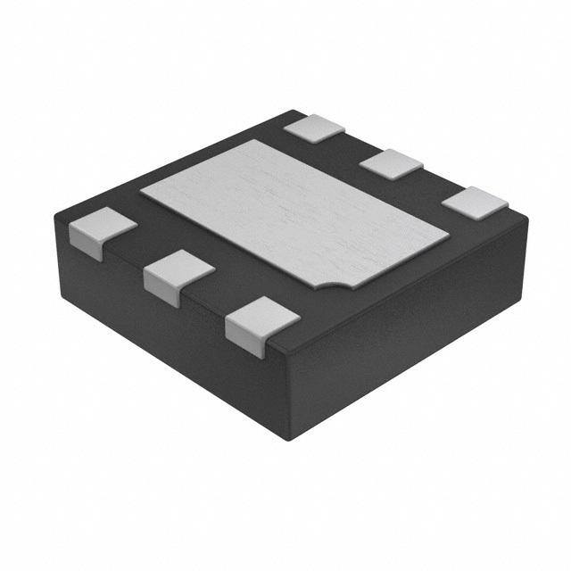
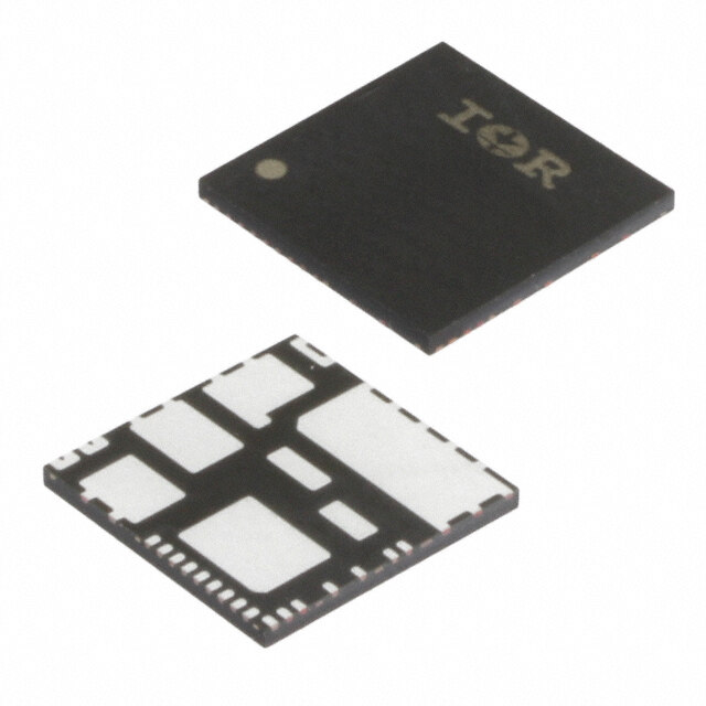
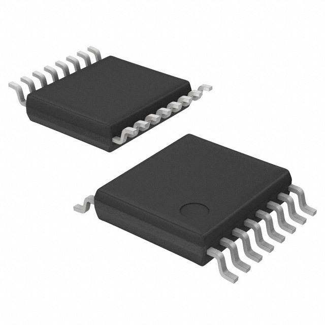
| 封装/外壳 | 6-VDFN 裸露焊盘 |
| 工作温度 | -40°C ~ 105°C |
| 应用 | 通用 |
| 接口 | 开/关 |
| 标准包装 | 1 |
| 电压-电源 | 1.8 V ~ 6 V |
| 电压-负载 | 1.8 V ~ 6 V |
| 电机类型-AC,DC | 无刷 DC(BLDC) |
| 电机类型-步进 | - |
| 电流-输出 | 500mA |
| 输出配置 | 全 H 桥,(1) 单 |


PDF Datasheet 数据手册内容提取
AH5794 SINGLE PHASE HALL EFFECT LATCH FAN MOTOR DRIVER Description Pin Assignments The AH5794 is a single chip solution for driving single-coil (Top View) brushless direct current (BLDC) fans and motors. The integrated full-bridge driver output stage uses soft switching to FG 1 6 NC minimize audible switching noise and electromagnetic interference (EMI) providing a low noise solution. V 2 5 V SS DD Low operating voltage down to 1.8V allows motor speed to be O2 3 4 O1 controlled by varying the supply voltage. T TSOT26 C To help protect the motor coil, the AH5794 provides Rotor U Lock Protection which shuts down the output drive if rotor lock D (Top View) O is detected. The device automatically re-starts when the rotor R lock is removed. Over temperature shutdown provides NC 1 6 FG P thermal protection for the device. W V 2 5 O2 DD E A Tachometer output is provided by open-drain Frequency O1 3 4 V N SS Generator (FG) Pin which allows external interface to monitor motor rotation or speed. The FG output is the magnetic U-DFN2020C-6 change frequency. The AH5794 is available in space saving and low profile TSOT26 and U-DFN2020C-6 packages. Features Applications • Supports single-coil full-wave BLDC fan drivers • 3V/ 3.3V/ 5V BLDC Cooling Fans • Built-in Hall sensor and input amplifier • Netbook/ Notebook BLDC fans • Operating voltage: 1.8V to 6V • Instruments cooling fans • VDD voltage speed control • Low Voltage/ Low Power BLDC Motors • Soft switching for low noise DC fan motor applications • Rotor Lock Protection (Lock detection, output shutdown and automatic re-start) • Thermal protection • Tachometer (FG) output • No external timing capacitor - Reduces the numbers of external components required • Low profile package: TSOT26 and U-DFN2020C-6 • Halogen and Antimony free “Green” packages. • Lead Free Finish/ RoHS Compliant AH5794 1 of 13 March 2012 Document number: DS35809 Rev. 1 - 2 www.diodes.com © Diodes Incorporated
AH5794 SINGLE PHASE HALL EFFECT LATCH FAN MOTOR DRIVER Typical Application Circuit T C U D O R P W E N Pin Descriptions Pin Name Description VDD Power supply pin V Ground pin SS O1 Output driving & sinking pin O2 Output driving & sinking pin NC No connection FG Frequency generator (Note 1) Notes: 1. The FG output is the same as the magnetic change frequency. AH5794 2 of 13 March 2012 Document number: DS35809 Rev. 1 - 2 www.diodes.com © Diodes Incorporated
AH5794 SINGLE PHASE HALL EFFECT LATCH FAN MOTOR DRIVER Functional Block Diagram (Note 2) T C U D O R P W E N Notes: 2.The AH5794 has an open-drain tachometer FG output that follows the magnetic change frequency. Typically a pull-up resistor of 10kΩ is recommended from FG pin to the supply voltage. AH5794 3 of 13 March 2012 Document number: DS35809 Rev. 1 - 2 www.diodes.com © Diodes Incorporated
AH5794 SINGLE PHASE HALL EFFECT LATCH FAN MOTOR DRIVER Absolute Maximum Ratings (T = 25°C, unless otherwise noted, Note 3) A Symbol Characteristics Values Unit VDD Supply Voltage 7 V IO(PEAK) Maximum Output Current (Peak) 1000 mA TSOT26 650 PD Power Dissipation mW U-DFN2020C-6 750 (Note 4) T TST Storage Temperature Range -65 ~ +150 oC C U ESD HBM Human Body Model ESD Protection 4 kV D Notes: 3. Stresses greater than the 'Absolute Maximum Ratings' specified above, may cause permanent damage to the device. These are stress ratings only; O functional operation of the device at these or any other conditions exceeding those indicated in this specification is not implied. Device reliability R may be affected by exposure to absolute maximum rating conditions for extended periods of time 4. U-DFN2020C-6 exposed pad soldered to minimum recommended landing pads (see Package Outline Dimension section) on a two-layer 2oz. P copper FR4 PCB (1.6mm thickness) with no thermal vias in exposed PADs or any copper flood connecting to the landing pattern of the exposed pad. W E N Recommended Operating Conditions (TA = 25°C) Symbol Parameter Conditions Min Max Unit VDD Supply Voltage at VDD pin DC supply speed control mode 1.8 6.0 V TA Operating Ambient Temperature Range Operating -40 +105 oC Electrical Characteristics (T = 25°C, V = 5V) A DD Symbol Characteristics Conditions Min Typ. Max Unit IDD Supply Current No Load - 2.2 - mA IOUT = 300mA 4.70 4.88 - V VOH Output Voltage High IOUT = 500mA 4.5 4.8 - V IOUT = 300mA - 0.12 0.3 V VOL Output Voltage Low IOUT = 500mA - 0.2 0.5 V Output voltage of N- and PMOS IOUT = 300mA 0.3 0.5 V V +V OH OL combined IOUT = 500mA 0.5 V TSW Output Switching Slope Duration 17Ω load on O1/O2 - 200 - μs ILEAK FG Output Leakage Current - - 5 μA VFGOL FG Output Voltage Low IFG = 5mA - - 0.4 V TON On Time 350 500 650 ms RDR Duty Ratio TOFF / TON - 10 - IC junction temperature thermal T _ 175 oC J SDN_TH shutdown threshold IC junction temperature thermal TJ_SDN_HYST 25 oC shutdown hysteresis AH5794 4 of 13 March 2012 Document number: DS35809 Rev. 1 - 2 www.diodes.com © Diodes Incorporated
AH5794 SINGLE PHASE HALL EFFECT LATCH FAN MOTOR DRIVER Magnetic Characteristics (T = 25°C, V = 1.8V to 6V, Note 5) A DD (1mT = 10 G) Symbol Parameter Min Typ. Max Unit BOP Operate Point 10 25 50 BRP Release Point -50 -25 -10 Gauss Bhy Hysteresis - 50 - Notes: 5. Magnetic characteristics may vary with supply voltage, operating temperature and after soldering. T C U D O Operating Characteristics R P O1 O2 W VOH VOH E s s N olt RP OFF olt OFF OP V V n n e i e i g g a a olt olt V V ut ut p p Out ON OP Out RP ON V V OL OL Brp 0 Bop Brp 0 Bop Magnetic Flux Density in Gauss Magnetic Flux Density in Gauss S N Marking side Marking side N S (U-DFN2020C-6) (TSOT26) AH5794 5 of 13 March 2012 Document number: DS35809 Rev. 1 - 2 www.diodes.com © Diodes Incorporated
AH5794 SINGLE PHASE HALL EFFECT LATCH FAN MOTOR DRIVER Operating Characteristics (Note 6, 7, 8 and 9) S Magentic N O2 T O1 C U D O Ton Toff R FG P Normal spinning Mechanical lock “Re-start spinning” W E N motor locked detected motor locked cleared Truth Table O1 O2 FG L H L H L H X L L (Note 9) Notes: 6. In “Normal spinning, the FG changes its state at each edge of O1. 7. When the motor locks with South pole at the Hall element, O2 is kept on “L” and O1 is a clock with Ton/Toff ratio. When motor locks with North pole at the Hall element, O1 is kept on “L”, O2 is a clock with Ton/Toff ratio. 8. When “Re-start spinning” occurs, the motor speed ramps up to the “Normal Spinning” speed from zero. Speed ramp-up profile depends on motor characteristics. 9. X: H or L depends on magnetic pole North or South AH5794 6 of 13 March 2012 Document number: DS35809 Rev. 1 - 2 www.diodes.com © Diodes Incorporated
AH5794 SINGLE PHASE HALL EFFECT LATCH FAN MOTOR DRIVER Application Note Motor Speed Control DC Supply Voltage (V ) Speed Control DD Motor speed can be controlled by varying the V supply voltage between 1.8V to 6V. DD With 5V nominal motor, changing V voltage between 5V to 1.8V, speed can be controlled from 100% to 36% typically. DD T Soft Switching C AH5794 uses soft switching of the motor coil current during commutation for to minimize audible switching noise and U electromagnetic interference (EMI) to provide a low noise solution. D O R P Vdd W E Vout 1 N Vout 2 Vss 200µs typ. AH5794 7 of 13 March 2012 Document number: DS35809 Rev. 1 - 2 www.diodes.com © Diodes Incorporated
AH5794 SINGLE PHASE HALL EFFECT LATCH FAN MOTOR DRIVER Thermal Performance Characteristics (1) Package type: TSOT26 TA (°C) 25 50 60 70 75 80 85 90 95 100 PD (mW) 651 521 469 417 391 365 339 313 286 260 TA (°C) 105 110 115 120 125 130 135 140 145 150 T PD (mW) 234 208 182 156 130 104 78 52 26 0 C U 700 D O 650 R 600 P W) m W N ( 500 O NE ATI 400 P SI S DI 300 R E W 200 O P 100 0 105 -40 25 50 75 100 125 150 TEMPERATURE (°C) Power Dissipation Curve AH5794 8 of 13 March 2012 Document number: DS35809 Rev. 1 - 2 www.diodes.com © Diodes Incorporated
AH5794 SINGLE PHASE HALL EFFECT LATCH FAN MOTOR DRIVER Thermal Performance Characteristics (cont.) (2) Package type: U-DFN2020C-6 (Note 10) T (°C) 25 50 60 70 75 80 85 90 95 100 A P (mW) 781 625 563 500 469 438 406 375 344 313 D T (°C) 105 110 115 120 125 130 135 140 145 150 A P (mW) 281 250 219 188 156 125 94 63 31 0 D T C U 900 D O 800 R W) 700 P m W ON ( 600 E PATI 500 N SI S 400 DI R E 300 W O P 200 100 0 105 -40 25 50 75 100 125 150 TEMPERATURE (°C) Power Dissipation Curve Notes: 10. U-DFN2020C-6 exposed pad soldered to minimum recommended landing pads (see Package Outline Dimension section) on a two-layer 2oz. copper FR4 PCB (1.6mm thickness) with no thermal vias in exposed PADs or any copper flood connecting to the landing pattern of the exposed pad. AH5794 9 of 13 March 2012 Document number: DS35809 Rev. 1 - 2 www.diodes.com © Diodes Incorporated
AH5794 SINGLE PHASE HALL EFFECT LATCH FAN MOTOR DRIVER Ordering Information AH5794 - XXX - 7 Package Packing WU : TSOT26 7 : Tape & Reel FDC : U-DFN2020C-6 T C U Package Packaging 7” Tape and Reel D Device Code (Note 11 & 12) Quantity Part Number Suffix O R AH5794-WU-7 WU TSOT26 3000/Tape & Reel -7 P AH5794-FDC-7 FDC U-DFN2020C-6 3000/Tape & Reel -7 W Notes: 11. Pad layout as shown on Diodes Inc. suggested pad layout document AP02001, which can be found on our website at E http://www.diodes.com/datasheets/ap02001.pdf N 12. EU Directive 2002/95/EC (RoHS) & 2011/65/EU (RoHS 2) compliant. No purposely added lead. Halogen and Antimony free. Please visit our website at http://www.diodes.com/products/lead_free.html Marking Information (1) Package type: TSOT26 Part Number Package Identification Code AH5794-WU-7 TSOT26 J4 (2) Package type: U-DFN2020C-6 ( Top View ) XX : Identification Code XX Y : Year : 0~9 W : Week : A~Z : 1~26 week; Y W X a~z : 27~52 week; z represents 52 and 53 week X : A~Z : Internal code Part Number Package Identification Code AH5794-FDC-7 U-DFN2020C-6 J4 AH5794 10 of 13 March 2012 Document number: DS35809 Rev. 1 - 2 www.diodes.com © Diodes Incorporated
AH5794 SINGLE PHASE HALL EFFECT LATCH FAN MOTOR DRIVER Package Outline Dimensions (All Dimensions in mm) (1) Package type: TSOT26 T C U D O R P W E N (2) Package Type: U-DFN2020C-6 Hall Sensor 1 0. ± 0.57/0.63 1.0 0.55±0.1 Top Mark 0.43mon. 0.05 C (Active area depth) x. a 0.08 C 5m Seating plane 5 C 0.1 C 6x-0.37 Pin#1 ID 0/0.02x0.15 1.95/2.075 A 0.57/0.63 B 1.55/1.75 0.30±0.1 5 R0.15 6x-0.4 0.9 1.95/2.075 0.86/1.06R 0.1 0.30/0.40 Die 0.651.59 2x- 0.15 C Land Pattern Recommendation (Unit:mm) 0.65nom. 0.2/0.3 0.05M C A B Top View Bottom View AH5794 11 of 13 March 2012 Document number: DS35809 Rev. 1 - 2 www.diodes.com © Diodes Incorporated
AH5794 SINGLE PHASE HALL EFFECT LATCH FAN MOTOR DRIVER Taping Orientation (1) Package Type: U-DFN2020C-6 T C U D O R P W E N Notes: 11. The taping orientation of the other package type can be found on our website at http://www.diodes.com/datasheets/ap02007.pdf. AH5794 12 of 13 March 2012 Document number: DS35809 Rev. 1 - 2 www.diodes.com © Diodes Incorporated
AH5794 SINGLE PHASE HALL EFFECT LATCH FAN MOTOR DRIVER IMPORTANT NOTICE DIODES INCORPORATED MAKES NO WARRANTY OF ANY KIND, EXPRESS OR IMPLIED, WITH REGARDS TO THIS DOCUMENT, INCLUDING, BUT NOT LIMITED TO, THE IMPLIED WARRANTIES OF MERCHANTABILITY AND FITNESS FOR A PARTICULAR PURPOSE (AND THEIR EQUIVALENTS UNDER THE LAWS OF ANY JURISDICTION). Diodes Incorporated and its subsidiaries reserve the right to make modifications, enhancements, improvements, corrections or other changes without further notice to this document and any product described herein. Diodes Incorporated does not assume any liability arising out of the application or use of this document or any product described herein; neither does Diodes Incorporated convey any license under its patent or trademark rights, nor the rights of others. Any Customer or user of this document or products described herein in such applications shall assume all risks of such use and will agree to hold Diodes Incorporated and all the companies whose products are represented on Diodes Incorporated website, harmless against all damages. T C Diodes Incorporated does not warrant or accept any liability whatsoever in respect of any products purchased through unauthorized U sales channel. Should Customers purchase or use Diodes Incorporated products for any unintended or unauthorized application, Customers shall D indemnify and hold Diodes Incorporated and its representatives harmless against all claims, damages, expenses, and attorney fees O arising out of, directly or indirectly, any claim of personal injury or death associated with such unintended or unauthorized application. R P Products described herein may be covered by one or more United States, international or foreign patents pending. Product names and markings noted herein may also be covered by one or more United States, international or foreign trademarks. W E LIFE SUPPORT N Diodes Incorporated products are specifically not authorized for use as critical components in life support devices or systems without the express written approval of the Chief Executive Officer of Diodes Incorporated. As used herein: A. Life support devices or systems are devices or systems which: 1. are intended to implant into the body, or 2. support or sustain life and whose failure to perform when properly used in accordance with instructions for use provided in the labeling can be reasonably expected to result in significant injury to the user. B. A critical component is any component in a life support device or system whose failure to perform can be reasonably expected to cause the failure of the life support device or to affect its safety or effectiveness. Customers represent that they have all necessary expertise in the safety and regulatory ramifications of their life support devices or systems, and acknowledge and agree that they are solely responsible for all legal, regulatory and safety-related requirements concerning their products and any use of Diodes Incorporated products in such safety-critical, life support devices or systems, notwithstanding any devices- or systems-related information or support that may be provided by Diodes Incorporated. Further, Customers must fully indemnify Diodes Incorporated and its representatives against any damages arising out of the use of Diodes Incorporated products in such safety-critical, life support devices or systems. Copyright © 2012, Diodes Incorporated www.diodes.com AH5794 13 of 13 March 2012 Document number: DS35809 Rev. 1 - 2 www.diodes.com © Diodes Incorporated
Mouser Electronics Authorized Distributor Click to View Pricing, Inventory, Delivery & Lifecycle Information: D iodes Incorporated: AH5794-WU-7 AH5794-FDC-7