ICGOO在线商城 > 集成电路(IC) > 嵌入式 - 微控制器 > ADUC843BSZ62-5
 Datasheet下载
- 型号: ADUC843BSZ62-5
- 制造商: Analog
- 库位|库存: xxxx|xxxx
- 要求:
| 数量阶梯 | 香港交货 | 国内含税 |
| +xxxx | $xxxx | ¥xxxx |
查看当月历史价格
查看今年历史价格
ADUC843BSZ62-5产品简介:
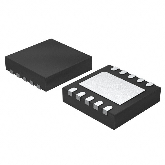
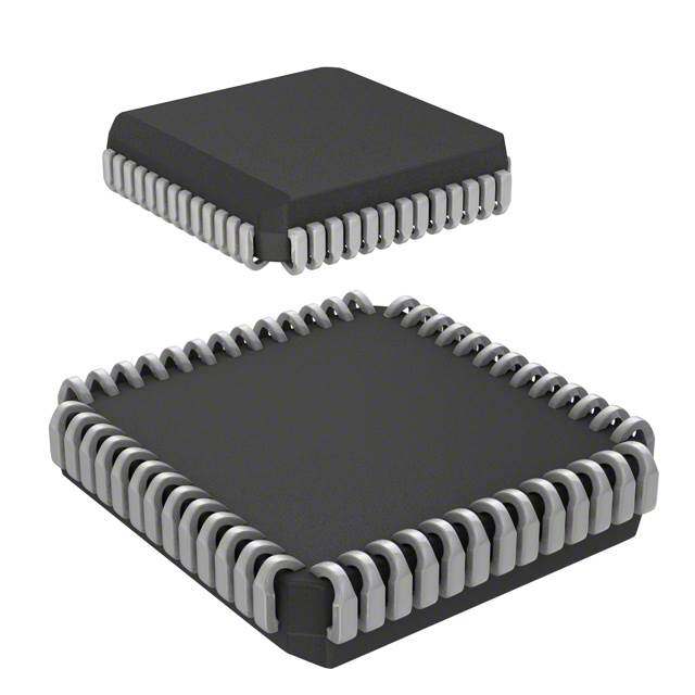
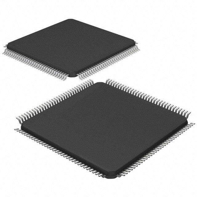
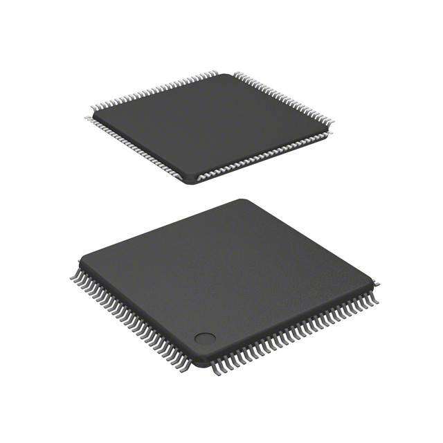
ICGOO电子元器件商城为您提供ADUC843BSZ62-5由Analog设计生产,在icgoo商城现货销售,并且可以通过原厂、代理商等渠道进行代购。 ADUC843BSZ62-5价格参考。AnalogADUC843BSZ62-5封装/规格:嵌入式 - 微控制器, 8052 微控制器 IC MicroConverter® ADuC8xx 8-位 16.78MHz 62KB(62K x 8) 闪存 52-MQFP(10x10)。您可以下载ADUC843BSZ62-5参考资料、Datasheet数据手册功能说明书,资料中有ADUC843BSZ62-5 详细功能的应用电路图电压和使用方法及教程。
ADUC843BSZ62-5 是 Analog Devices Inc. 生产的一款嵌入式微控制器,属于 ADuC843 系列。该系列微控制器集成了高性能的模拟和数字外设,适用于多种工业、医疗及消费类应用场景。

 主要应用场景:

1. 工业自动化:
   - 传感器数据采集:ADUC843BSZ62-5 集成了多个高精度 ADC(模数转换器),能够实时采集来自温度、压力、湿度等传感器的数据。其多通道输入能力使其适合用于复杂的工业监控系统。
   - 电机控制:内置 PWM(脉宽调制)功能,可以精确控制电机的速度和位置,广泛应用于工厂自动化设备中的伺服电机控制系统。

2. 医疗设备:
   - 便携式医疗仪器:如血糖仪、心率监测仪等。ADUC843BSZ62-5 的低功耗设计和集成的模拟前端使其非常适合电池供电的便携式医疗设备。
   - 患者监护系统:通过集成的 ADC 和 DAC(数模转换器),它可以处理来自各种生理信号传感器的数据,并进行实时分析和显示。

3. 消费电子:
   - 智能家居设备:如智能温控器、烟雾报警器等。ADUC843BSZ62-5 可以通过集成的通信接口(如 SPI、I2C、UART)与外部设备或网络模块连接,实现远程监控和控制。
   - 便携式电子产品:例如手持式测量工具、运动追踪器等。其紧凑的设计和丰富的外设接口使得它成为这些产品的理想选择。

4. 环境监测:
   - 空气质量监测:可用于检测 PM2.5、CO2 等污染物浓度,通过集成的 ADC 读取传感器数据并进行处理。
   - 水质量监测:用于检测水质参数如 pH 值、溶解氧等,提供准确的环境数据反馈。

总之,ADUC843BSZ62-5 凭借其强大的模拟和数字处理能力、低功耗特性以及灵活的外设配置,适用于需要高精度数据采集和处理的多种应用场景。
| 参数 | 数值 |
| A/D位大小 | 12 bit |
| 产品目录 | 集成电路 (IC)半导体 |
| 描述 | IC MCU 8BIT 62KB FLASH 52MQFP8位微控制器 -MCU 16MIPS 8-CH 12B ADC Microconverter |
| EEPROM容量 | - |
| 产品分类 | |
| I/O数 | 32 |
| 品牌 | Analog Devices Inc |
| 产品手册 | |
| 产品图片 |
|
| rohs | 符合RoHS无铅 / 符合限制有害物质指令(RoHS)规范要求 |
| 产品系列 | 嵌入式处理器和控制器,微控制器 - MCU,8位微控制器 -MCU,Analog Devices ADUC843BSZ62-5MicroConverter® ADuC8xx |
| 数据手册 | |
| 产品型号 | ADUC843BSZ62-5 |
| RAM容量 | 2.25K x 8 |
| 产品目录页面 | |
| 产品种类 | 8位微控制器 -MCU |
| 供应商器件封装 | 52-MQFP(10x10) |
| 其它名称 | ADUC843BSZ625 |
| 包装 | 托盘 |
| 可用A/D通道 | 8 |
| 可编程输入/输出端数量 | 34 |
| 商标 | Analog Devices |
| 处理器系列 | ADUC843 |
| 外设 | DMA,PSM,PWM,温度传感器,WDT |
| 安装风格 | SMD/SMT |
| 定时器数量 | 3 Timer |
| 封装 | Tray |
| 封装/外壳 | 52-QFP |
| 封装/箱体 | QFP-52 |
| 工作温度 | -40°C ~ 85°C |
| 工厂包装数量 | 96 |
| 振荡器类型 | 内部 |
| 接口类型 | I2C/SPI/UART |
| 数据RAM大小 | 2304 B |
| 数据总线宽度 | 8 bit |
| 数据转换器 | A/D 8x12b |
| 最大工作温度 | + 85 C |
| 最大时钟频率 | 16 MHz |
| 最小工作温度 | - 40 C |
| 标准包装 | 1 |
| 核心 | 8052 |
| 核心处理器 | 8052 |
| 核心尺寸 | 8-位 |
| 片上ADC | Yes |
| 片上DAC | With DAC |
| 电压-电源(Vcc/Vdd) | 4.75 V ~ 5.25 V |
| 电源电压-最大 | 5.25 V |
| 电源电压-最小 | 4.75 V |
| 程序存储器大小 | 62 kB |
| 程序存储器类型 | 闪存 |
| 程序存储容量 | 62KB(62K x 8) |
| 系列 | ADUC843 |
| 输入/输出端数量 | 34 I/O |
| 连接性 | I²C, SPI, UART/USART |
| 速度 | 16.78MHz |


PDF Datasheet 数据手册内容提取
MicroConverter® Multichannel 12-Bit ADC with Embedded 62 kB Flash and Single-Cycle MCU Anomaly Sheet for Silicon Rev. E ADuC841/ADuC842/ADuC843 This anomaly list represents the known bugs, anomalies, and workarounds for the ADuC841, ADuC842, and ADuC843 MicroConverter products. The anomalies listed apply to all ADuC841/ADuC842/ADuC843 packaged material branded as follows: First(CSP) /Second (PQFP) Line ADuC841 or ADuC842 or ADuC843 Third (CSP) / Fourth Line (PQFP) E20 Analog Devices, Inc. is committed, through future silicon revisions, to continuously improving silicon functionality. Analog Devices tries to ensure that these future silicon revisions remain compatible with your present software/systems implementing the recommended workarounds outlined here. ADuC841/ADuC842/ADuC843 SILICON REVISION HISTORY Silicon Kernel Revision Revision Identifier Identifier Chip Marking Silicon Status Anomaly Sheet No. of Reported Anomalies E 0 All silicon branded Release Rev. 0 8 ADUC841BS or ADuC841BCP ADuC842BS or ADuC842BCP ADuC843BS or ADuC843BCP Third/Fourth Line: E20 E 0 All silicon branded Release Rev. A 11 ADUC841BS or ADuC841BCP ADuC842BS or ADuC842BCP ADuC843BS or ADuC843BCP Third/Fourth Line: E20 Rev. A Information furnished by Analog Devices is believed to be accurate and reliable. However, no responsibility is assumed by Analog Devices for its use, nor for any infringements of patents or other rights of third parties that may result from its use. One Technology Way, P.O. Box 9106, Norwood, MA 02062-9106, U.S.A. Specifications subject to change without notice. No license is granted by implication or otherwise under any patent or patent rights of Analog Devices. Trademarks and Tel: 781.329.4700 www.analog.com registered trademarks are the property of their respective owners. Fax: 781.326.8703 © 2004 Analog Devices, Inc. All rights reserved.
ADuC841/ADuC842/ADuC843 ANOMALIES 1. Mode 0 UART Operation [er001] Background: UART Mode 0 allows the UART to function in an 8-bit shift register mode. Issue: UART Mode 0 is nonfunctional on the ADuC841/ADuC842/ADuC843. Workaround: None. Related Issues: None. 2. Use of the Extended Stack Pointer [er002] Background: The extended stack pointer allows the stack to overflow into internal XRAM. Issue: A PUSH onto the extended stack when it is the first instruction within a subroutine results in the return address being overwritten. Workaround: For Assembly code, insert a NOP as the first instruction in any subroutine. For C code, there is currently no workaround. Related Issues: None. 3. Use of I2C in Slave Mode with Stop Interrupt Enabled [er003] Background: In slave mode, the I2C interface can be configured to generate an interrupt due to a start, repeated start, data, or stop condition. The I2C interrupt decode bits (I2CID0 and I2CID1) in I2CCON indicate the source of the interrupt. If the stop interrupt is enabled via the I2CSI bit, an interrupt is generated when the slave receives a stop condition. Issue A: In the I2C interrupt service routine, if the I2CI bit or I2CDAT register is accessed during a stop interrupt, the I2C bus will fail to respond to further I2C communication. Workaround A: When a stop interrupt is detected, the user should reset the I2C bus by using the I2CRS bit. Issue B: When the stop interrupt is enabled, on occasion the I2C interrupt decode bits indicate that a start, repeated start, or DATA interrupt occurred when the source was in fact a stop interrupt. If this happens the user may try to clear I2CI or read I2CDAT, resulting in the bus failing to respond to further I2C communication. Workaround B: Tie the SCLOCK pin to an I/O pin; This allows the state of SCLOCK to be read. SCLOCK is high only during an interrupt if the source is a stop interrupt. Related Issues: er004: Use of I2C in slave mode with stop interrupt disabled. 4. Use Of I2C in Slave Mode with Stop Interrupt Disabled [er004] Background: In slave mode, the I2C interface can be configured to generate an interrupt due to a start, repeated start, data, or stop condition. The I2C interrupt decode bits (I2CID0 and I2CID1) in I2CCON indicate the source of the interrupt. Issue: Once one repeated start is detected by the I2C interface, all subsequent start conditions are detected as a repeated start even if a stop bit has been received between data transfers. Workaround: None. Related Issues: None. 5. I2C Data Transfer [er005] Background: The I2CDAT register is used to read or write data to the I2C bus. The I2CDAT register has an SFR address of 0x9A. Issue A: During an I2C transfer if a user accesses the RAM address 0x9A the contents of the I2CDAT SFR can be modified. Workaround A: For Assembly code: Do not use memory location 0x9A For C code: Assign a dummy variable to location 0x9A using the following code: idata unsigned int ui32Dummy[2] _at_ 0x9A; Issue B: During an I2C transfer, if a user executes either of the following instructions, the contents of the I2CDAT SFR can be modified. MOV dest,#9AH SUBB A,R2 Workaround B: To prevent code from changing the contents of the I2CDAT SFR make sure that neither of these instructions are executed during an I2C transfer. Issue C: A small percentage (<3%) of I2C stop conditions received by a slave cause the I2C bus to enter a state where the subsequent START+matching address is not acknowledged. Workaround C: If a second START+matching address is issued following a NACK, this is detected correctly. Related Issues: None. Rev. A | Page 2 of 4
ADuC841/ADuC842/ADuC843 6. SPI Interface [er006] Background: The SPI can either be used on the standard pins or can be moved to P3.3, P3.4, and P3.5 by setting the MSPI bit in CFG841/CFG842. When the MSPI bit is set, P3.3 should be MISO, P3.4 MOSI, and P3.5 SCLOCK. Issue A: By setting the MSPI bit, the P3.3, P3.4, and P3.5 have the following configuration: P3.3 = MISO, P3.4 = SCLOCK, P3.5 = MOSI Workaround A: None. Issue B: When the ADuC841/ADuC842/ADuC843 is set up as an SPI slave, the device may receive or transmit bytes incorrectly. Workaround B: Incorporate checksums into all communication with the ADuC841/ADuC842/ADuC843 slave. This allows the master devices to retransmit if an error occurs. Related Issues: None. 7. Interrupts During Reading/Writing to Data FLASH/EE [er007] Background: There are 4 kB of DATAFLASH/EE that can be used for nonvolatile data storage. Issue: If an interrupt occurs during a DATAFLASH/EE read or write operation, code execution following the ISR may resume at a random program memory address. Workaround: Disable all interrupts prior to a read or write operation. This can be done by setting the EA bit to 0. Related Issues: None. 8. PWM Operation [er008] Background: The PWM output rate is determined by the PWMxH and PWMxL registers for the PWM0 and PWM1 outputs. Issue: Modifying RAM Address 0x2E causes the PWM timer to be reset. Workaround: For Assembly code: Do not use memory location 0x2E. For C code: Assign a dummy variable to location 0x2E using the following code: idata unsigned int ui32Dummy[2] _at_ 0x2E; Related Issues: None. 9. Watchdog Timer [er009] Background: The ADuC841, ADuC842, and ADuC843 incorporate a Watchdog Timer. The purpose of the WDT is to ensure the part is never stuck in an endless loop by generating either a hardware reset or an interrupt event that vectors to the WDT ISR. Issue: If the WDT generates an interrupt as opposed to a hardware reset, and if the ISR subsequently sets up the WDT to time out to a hardware reset, the reset is ignored. Workaround: Ensure that a double write to the WDCON is executed inside the ISR with the first write being a reset of the WDT. For example: void isr_wdt( void ) interrupt 11 { WDWR = 1; // This first WDT write is required to get the WDT to work inside the ISR. WDCON = 0x60;// Reset WDT. WDWR = 1; // Now set the WDT to the required 1s timeout WDCON = 0x62;// select reset after 1000mS while(1); } void main(void) { EA = 0; WDWR = 1; // Allow write to WDCON WDCON = 0x6A; // timeout=1000mS, WDT enable, WDT ISR Interrupt while (1); } Related Issues: None. Rev. A | Page 3 of 4
ADuC841/ADuC842/ADuC843 10. Level Triggered Interrupt Operation [er010] Background: The ADuC841/ADuC842/ADuC843 incorporate two external interrupt sources (INT0 and INT1) that can be configured to respond to either an edge event or a level event. Issue: If an interrupt occurs on the INT0 or INT1 pins and is then removed within one core instruction cycle, the interrupt vector address that is generated may be incorrect resulting in a vector to 0x0000. This effectively restarts code execution. Workaround: To ensure that this does not occur the level triggered interrupt source must be kept low for a minimum of 9 core clock cycles. Related Issues: None. 11. Stack Pointer in ULOAD Mode [er011] Background: When starting user code, the stack pointer should, by default, be initialized to Address 0x07. Issue: In ULOAD mode, the stack pointer defaults to 0x03 causing conflict between RAM locations R4 to R7 and the stack. Workaround: Manually change, in code, the stack pointer address to 0x07 or to the address that is required upon entry to ULOAD mode, that is, MOV SP, #07H or SP = 0x07; Related Issues: None. ADuC841/ADuC842/ADuC843 SILICON ANOMALIES Anomaly No. Description Status er001 Mode 0 UART Operation Pending er002 Use of the Extended Stack Pointer Pending er003 Use of I2C in Slave Mode with Stop Interrupt Enabled Pending er004 Use Of I2C in Slave Mode with Stop Interrupt Disabled Pending er005 I2C Data Transfer Pending er006 SPI Interface Pending er007 Interrupts During Reading/Writing to Data FLASH/EE Pending er008 PWM Operation Pending er009 Watchdog Timer Pending er010 Level Triggered Interrupt Operation Pending er011 Stack Pointer in ULOAD Mode Pending Purchase of licensed I2C components of Analog Devices or one of its sublicensed Associated Companies conveys a license for the purchaser under the Philips I2C Patent Rights to use these components in an I2C system, provided that the system conforms to the I2C Standard Specification as defined by Philips. © 2004 Analog Devices, Inc. All rights reserved. Trademarks and registered trademarks are the property of their respective owners. S03260–0–7/04(A) Rev. A | Page 4 of 4
Mouser Electronics Authorized Distributor Click to View Pricing, Inventory, Delivery & Lifecycle Information: A nalog Devices Inc.: EVAL-ADUC841QSPZ EVAL-ADUC841QSZ EVAL-ADUC842QSPZ EVAL-ADUC842QSZ ADUC843BSZ62-3 ADUC843BCPZ62-3 ADUC842BCPZ32-5 ADUC842BSZ62-5 ADUC841BCPZ62-3 ADUC842BCPZ8-5 ADUC842BSZ62-3 ADUC842BCPZ62-3 ADUC843BCPZ32-3 ADUC842BCPZ32-3 ADUC843BCPZ8-5 ADUC841BCPZ8-5 ADUC842BCPZ8-3 ADUC843BSZ62-5 USB-EA-CONVZ ADUC843BCPZ8-3 ADUC842BCPZ62- 5 ADUC841BCPZ62-5 ADUC841BSZ62-3 ADUC843BCP32Z-5 ADUC843BCP62Z-5 ADUC841BCPZ8-3 ADUC841BSZ62-5