ICGOO在线商城 > 集成电路(IC) > 数据采集 - 模数转换器 > ADS7800JU
 Datasheet下载
- 型号: ADS7800JU
- 制造商: Texas Instruments
- 库位|库存: xxxx|xxxx
- 要求:
| 数量阶梯 | 香港交货 | 国内含税 |
| +xxxx | $xxxx | ¥xxxx |
查看当月历史价格
查看今年历史价格
ADS7800JU产品简介:
ICGOO电子元器件商城为您提供ADS7800JU由Texas Instruments设计生产,在icgoo商城现货销售,并且可以通过原厂、代理商等渠道进行代购。 ADS7800JU价格参考。Texas InstrumentsADS7800JU封装/规格:数据采集 - 模数转换器, 12 Bit Analog to Digital Converter 1 Input 1 SAR 24-SOIC。您可以下载ADS7800JU参考资料、Datasheet数据手册功能说明书,资料中有ADS7800JU 详细功能的应用电路图电压和使用方法及教程。
Texas Instruments(德州仪器)的ADS7800JU是一款8位、逐次逼近寄存器(SAR)型模数转换器(ADC),广泛应用于各种数据采集系统中。以下是其主要应用场景:

 1. 工业自动化与控制
ADS7800JU在工业自动化领域有广泛应用,特别是在需要高精度数据采集的场合。例如,在温度、压力、流量等传感器信号的采集和处理中,该器件能够将模拟信号精确转换为数字信号,供微控制器或处理器进一步处理。它适用于工厂自动化、过程控制系统以及各类工业监测设备。

 2. 医疗设备
在医疗设备中,ADS7800JU可以用于心电图(ECG)、血压计、血糖仪等设备中的信号采集。由于这些设备对精度和响应速度有较高要求,ADS7800JU的快速转换时间和低功耗特性使其成为理想选择。此外,它的单电源供电设计简化了电路设计,降低了系统的复杂性。

 3. 汽车电子
在汽车电子系统中,ADS7800JU可用于发动机管理、车身控制、安全系统等模块的数据采集。例如,它可以用于采集传感器信号,如油门位置、车速、温度等,并将其转换为数字信号供车载计算机处理。其宽工作温度范围(-40°C至+85°C)使其能够在严苛的汽车环境中稳定工作。

 4. 便携式设备
对于便携式设备,如手持式测量仪器、无线传感器节点等,ADS7800JU的低功耗特性尤为重要。它可以在电池供电的情况下长时间工作,同时保持较高的转换精度。此外,其小型封装(SOIC-8)使得它适合用于空间受限的应用场景。

 5. 通信与网络设备
在通信和网络设备中,ADS7800JU可以用于信号调理和监控模块。例如,在基站、路由器等设备中,它可以用于采集环境温度、电源电压等关键参数,确保设备的正常运行。其高集成度和易用性减少了外部元件的需求,简化了设计流程。

综上所述,ADS7800JU凭借其高精度、低功耗、宽温度范围和易于集成的特点,广泛应用于工业、医疗、汽车、便携式设备及通信等领域,满足了多种数据采集需求。
| 参数 | 数值 |
| 产品目录 | 集成电路 (IC)半导体 |
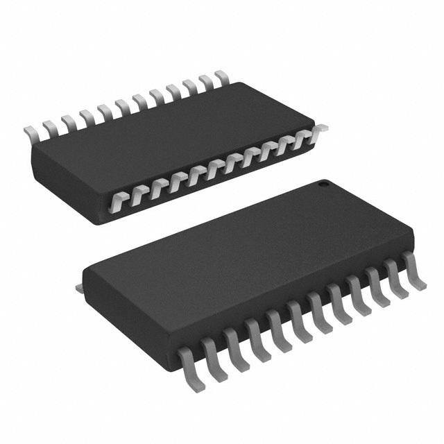
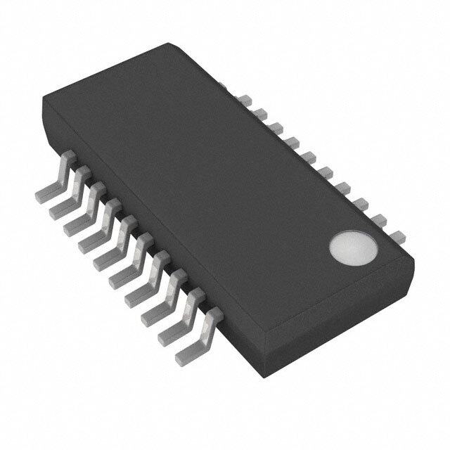
| 描述 | IC 12 BIT A/D CONV 24 SOIC模数转换器 - ADC 12-Bit 3us Sampling |
| 产品分类 | |
| 品牌 | Texas Instruments |
| 产品手册 | |
| 产品图片 |
|
| rohs | 符合RoHS无铅 / 符合限制有害物质指令(RoHS)规范要求 |
| 产品系列 | 数据转换器IC,模数转换器 - ADC,Texas Instruments ADS7800JU- |
| 数据手册 | |
| 产品型号 | ADS7800JU |
| 产品培训模块 | http://www.digikey.cn/PTM/IndividualPTM.page?site=cn&lang=zhs&ptm=13240 |
| 产品目录页面 | |
| 产品种类 | 模数转换器 - ADC |
| 位数 | 12 |
| 供应商器件封装 | 24-SOIC |
| 信噪比 | 73 dB |
| 分辨率 | 12 bit |
| 制造商产品页 | http://www.ti.com/general/docs/suppproductinfo.tsp?distId=10&orderablePartNumber=ADS7800JU |
| 包装 | 管件 |
| 单位重量 | 624.400 mg |
| 商标 | Texas Instruments |
| 安装类型 | 表面贴装 |
| 安装风格 | SMD/SMT |
| 封装 | Tube |
| 封装/外壳 | 24-SOIC(0.295",7.50mm 宽) |
| 封装/箱体 | SOIC-24 |
| 工作温度 | -40°C ~ 85°C |
| 工作电源电压 | 4.75 V to 5.25 V |
| 工厂包装数量 | 25 |
| 接口类型 | Parallel |
| 数据接口 | 并联 |
| 最大功率耗散 | 215 mW |
| 最大工作温度 | + 70 C |
| 最小工作温度 | 0 C |
| 标准包装 | 25 |
| 电压参考 | 2 V |
| 电压源 | 模拟和数字,双 ± |
| 系列 | ADS7800 |
| 结构 | SAR |
| 转换器数 | 1 |
| 转换器数量 | 1 |
| 转换速率 | 333 kS/s |
| 输入数和类型 | 2 个单端,双极 |
| 输入类型 | Single-Ended |
| 通道数量 | 1 Channel |
| 采样率(每秒) | 333k |


- 商务部:美国ITC正式对集成电路等产品启动337调查
- 曝三星4nm工艺存在良率问题 高通将骁龙8 Gen1或转产台积电
- 太阳诱电将投资9.5亿元在常州建新厂生产MLCC 预计2023年完工
- 英特尔发布欧洲新工厂建设计划 深化IDM 2.0 战略
- 台积电先进制程称霸业界 有大客户加持明年业绩稳了
- 达到5530亿美元!SIA预计今年全球半导体销售额将创下新高
- 英特尔拟将自动驾驶子公司Mobileye上市 估值或超500亿美元
- 三星加码芯片和SET,合并消费电子和移动部门,撤换高东真等 CEO
- 三星电子宣布重大人事变动 还合并消费电子和移动部门
- 海关总署:前11个月进口集成电路产品价值2.52万亿元 增长14.8%


PDF Datasheet 数据手册内容提取
ADS7800 SBAS001A – OCTOBER 1989 – REVISED FEBRUARY 2004 µ 12-Bit 3 s Sampling ANALOG-TO-DIGITAL CONVERTER FEATURES DESCRIPTION (cid:1) 333k SAMPLES PER SECOND The ADS7800 is a complete 12-bit sampling analog-to- (cid:1) STANDARD ±10V AND ±5V INPUT RANGES digital (A/D) converter using state-of-the-art CMOS structures. It contains a complete 12-bit successive (cid:1) DC PERFORMANCE OVER TEMP: approximation A/D converter with internal sample/hold, No Missing Codes reference, clock, digital interface for microprocessor 1/2LSB Integral Linearity Error control, and three-state output drivers. 3/4LSB Differential Linearity Error The ADS7800 is specified at a 333kHz sampling rate. (cid:1) AC PERFORMANCE OVER TEMP: Conversion time is factory set for 2.70µs max over 72dB Signal-to-Noise Ratio temperature, and the high-speed sampling input stage 80dB Spurious-Free Dynamic Range insures a total acquisition and conversion time of 3µs –80dB Total Harmonic Distortion max over temperature. Precision, laser-trimmed scaling (cid:1) INTERNAL SAMPLE/HOLD, REFERENCE, resistors provide industry-standard input ranges of ±5V or ±10V. CLOCK, AND THREE-STATE OUTPUTS (cid:1) POWER DISSIPATION: 215mW max AC and DC performance are completely specified. Two grades based on linearity and dynamic performance are (cid:1) PACKAGE: 24-Pin Single-Wide DIP available to provide the optimum price/performance fit in 24-Lead SOIC a wide range of applications. The 24-pin ADS7800 is available in plastic and side- braze hermetic 0.3" wide DIPs, and in an SOIC package. It operates from a +5V supply and either a –12V or –15V supply. The ADS7800 is available in grades specified over 0°C to +70°C and –40°C to +85°C temperature ranges. Control Clock SAR BUSY Logic Output Latches ±10V IN CDAC And Three Three State ±5V IN State Parallel Drivers Output Internal Comparator Data 2V Ref Bus Reference Out Please be aware that an important notice concerning availability, standard warranty, and use in critical applications of Texas Instruments semiconductor products and disclaimers thereto appears at the end of this data sheet. All trademarks are the property of their respective owners. PRODUCTION DATA information is current as of publication date. Copyright © 1989-2004, Texas Instruments Incorporated Products conform to specifications per the terms of Texas Instruments standard warranty. Production processing does not necessarily include testing of all parameters. www.ti.com
SPECIFICATIONS ELECTRICAL At T = T to T , Sampling Frequency, f , = 333kHz, –V = –15V, V = +5V, unless otherwise specified. A MIN MAX S S S ADS7800JP/JU/AH ADS7800KP/KU/BH PARAMETER CONDITIONS MIN TYP MAX MIN TYP MAX UNITS RESOLUTION 12 * Bits ANALOG INPUT Voltage Ranges ±10V/±5V * V Impedance ±10V Range 4.4 6.3 8.1 * * * kΩ ±5V Range 2.9 4.2 5.4 * * * kΩ THROUGHPUT SPEED Conversion Time Conversion Alone 2.5 2.7 * * µs Complete Cycle Acquisition+Conversion 2.6 3.0 * * µs Throughput Rate 333 380 * * kHz DC ACCURACY Full Scale Error(1) ±0.50 ±0.35 % Full Scale Error Drift 6 * ppm/°C Integral Linearity Error ±1 ±1/2 LSB(2) Differential Linearity Error ±1 ±3/4 LSB No Missing Codes Ensured Ensured Bipolar Zero(1) ±4 ±2 LSB Bipolar Zero Drift 1 * ppm/°C Power Supply Sensitivity –16.5V < –V < –13.5V ±1/2 * LSB S –12.6V < –V < –11.4V ±1/2 * LSB S +4.75V < V < +5.25V ±1 ±1/2 LSB S Transition Noise(3) 0.1 * LSB AC ACCURACY Spurious-Free Dynamic Range f = 47kHz 74 77 77 80 dB(4) IN Total Harmonic Distortion f = 47kHz –77 –74 –80 –77 dB IN Two-tone Intermodulation Distortion f = 24.4kHz (–6dB) –77 –74 –80 –77 dB IN1 f = 28.5kHz (–6dB) IN2 Signal-to-(Noise + Distortion) Ratio f = 47kHz 67 70 69 72 dB IN Signal-to-Noise Ratio (SNR) f = 47kHz 68 71 70 73 dB IN SAMPLING DYNAMICS Aperture Delay 13 * ns Aperture Jitter 150 * ps, rms Transient Response(5) 130 * ns Overvoltage Recovery(6) 150 * ns INTERNAL REFERENCE VOLTAGE Voltage 1.9 2.0 2.1 * * * V Source Current Available 10 * µA for External Loads DIGITAL INPUTS Logic Levels V –0.3 +0.8 * * V IL V +2.4 +5.3 * * V IH I –5 * µA IL I +5 * µA IH DIGITAL OUTPUTS Data Format Parallel, 12-bit or 8-bit/4-bit Data Coding Binary Offset Binary V I = 1.6mA 0.0 +0.4 * * V OL SINK V I = 500µA +2.4 +5.0 * * V OH SOURCE I (High-Z State) ±0.1 ±5 * * µA LEAKAGE POWER SUPPLIES Rated Voltage –V –11.4 –15 –16.5 * * * V S V (V and V ) +4.75 +5.0 +5.25 * * * V S SA SD Current –I 3.5 6 * * mA S I 18 25 * * mA S Power Consumption 135 215 * * mW ADS7800 2 www.ti.com SBAS001A
SPECIFICATIONS (CONT) ELECTRICAL At T = T to T , Sampling Frequency, f , = 333kHz, –V = –15V, V = +5V, unless otherwise specified. A MIN MAX S S S ADS7800JP/JU/AH ADS7800KP/KU/BH PARAMETER CONDITIONS MIN TYP MAX MIN TYP MAX UNITS TEMPERATURE RANGE Specification JP/JU/KP/KU 0 +70 * * °C AH/BH –40 +85 * * °C Operating JP/KP/JU/KU –40 +85 * * °C Storage –65 +150 * * °C * Same as specification for ADS7800JP/JU/AH. NOTES:(1) Adjustable to zero with external potentiometer. (2)LSB means Least Significant Bit. For ADS7800, 1LSB = 2.44mV for the ±5V range, 1LSB = 4.88mV for the ±10V range. (3)Noise was characterized over temperature near full scale, 0V, and negative full scale. 0.1LSB represents a typical rms level of noise at the worst case, which was near full scale input at +125°C. (4)All specifications in dB are referred to a full-scale input, either ±10V or ±5V. (5)For full scale step input, 12-bit accuracy attained in specified time. (6)Recovers to specified performance in specified time after 2 x F input overvoltage. S ABSOLUTE MAXIMUM RATINGS ELECTROSTATIC DISCHARGE SENSITIVITY –V to ANALOG COMMON............................................................–16.5V S V to DIGITAL COMMON....................................................................+7V S Pin 23 (VSD) to Pin 24 (VSA)........................................................... ±0.3V The ADS7800 is an ESD (electrostatic discharge) sensitive ANALOG COMMON to DIGITAL COMMON.......................................±1V device. The digital control inputs have a special FET struc- Control Inputs to DIGITAL COMMON.............................–0.3 to V + 0.3V S Analog Input Voltage..........................................................................±20V ture, which turns on when the input exceeds the supply by Maximum Junction Temperature.....................................................160°C 18V, to minimize ESD damage. However, permanent damage Internal Power Dissipation.............................................................750mW may occur on unconnected devices subject to high energy Lead Temperature (soldering, 10s)...............................................+300°C Thermal Resistance, θ : electrostatic fields. When not in use, devices must be stored in JA Plastic DIP................................................................................100°C/W conductive foam or shunts. The protective foam should be SOIC.........................................................................................100°C/W discharged to the destination socket before devices are re- Ceramic......................................................................................50°C/W moved. PACKAGE/ORDERING INFORMATION For the most current package and ordering information, see the Package Option Addendum located at the end of this data sheet. ADS7800 3 SBAS001A www.ti.com
PIN ASSIGNMENTS PIN CONFIGURATION PIN # NAME DESCRIPTION Top View DIP/SOIC 1 IN1 ±10V Analog Input. Connected to GND for ±5V range. 2 IN2 ±5V Analog Input. Connected to GND for ±10V range. 3 REF +2V Reference Output. Bypass to GND with 22µF to 47µF Tantalum. Buffer for external loads. IN1 1 24 VSA 4 AGND Analog Ground. Connect to pin 13. IN2 2 23 V SD 5 D11 Data Bit 11. Most Significant Bit (MSB). REF 3 22 –V 6 D10 Data Bit 10. S 7 D9 Data Bit 9. AGND 4 21 BUSY 8 D8 Data Bit 8. D11 5 20 CS 9 D7 Data Bit 7 if HBE is LOW; LOW if HBE is HIGH. 10 D6 Data Bit 6 if HBE is LOW; LOW if HBE is HIGH. D10 6 19 R/C 11 D5 Data Bit 5 if HBE is LOW; LOW if HBE is HIGH. D9 7 18 HBE 12 D4 Data Bit 4 if HBE is LOW; LOW if HBE is HIGH. D8 8 17 D0 13 DGND Digital Ground. Connect to pin 4. 14 D3 Data Bit 3 if HBE is LOW; Data Bit 11 if HBE is HIGH. D7 9 16 D1 15 D2 Data Bit 2 if HBE is LOW; Data Bit 10 if HBE is HIGH. D6 10 15 D2 16 D1 Data Bit 1 if HBE is LOW; Data Bit 9 if HBE is HIGH. 17 D0 Data Bit 0 if HBE is LOW. Least Significant Bit (LSB); D5 11 14 D3 Data Bit 8 if HBE is HIGH. D4 12 13 DGND 18 HBE High Byte Enable. When held LOW, data output as 12 bits in parallel. When held HIGH, four MSBs presented on pins 14-17, pins 9-12 output LOWs. Must be LOW to initiate conversion. 19 R/C Read/Convert. Falling edge initiates conversion when CS is LOW, HBE is LOW, and BUSY is HIGH. 20 CS Chip Select. Outputs in Hi-Z state when HIGH. Must be LOW to initiate conversion or read data. 21 BUSY Busy. Output LOW during conversion. Data valid on rising edge in Convert Mode. 22 –V Negative Power Supply. –12V or –15V. Bypass to GND. S 23 V Positive Digital Power Supply. +5V. Connect to pin 24, SD and bypass to GND. 24 V Positive Analog Power Supply. +5V. Connect to pin 23, SA and bypass to GND. ADS7800 4 www.ti.com SBAS001A
TYPICAL PERFORMANCE CURVES At +V = +5V, –V = –15V, and T = +25°C, unless otherwise noted. All plots use 1024 point FFTs. S S A FREQUENCY SPECTRUM (10kHz f ) FREQUENCY SPECTRUM (50kHz f ) IN IN 0 0 f = 10kHz f = 50kHz –20 fIN = 330kHz –20 fIN = 330kHz TSA M=P L2IN5G°C TSA M=P L2IN5G°C A A B) –40 B) –40 d d e ( e ( ud –60 ud –60 nit nit g g a a M –80 M –80 –100 –100 –120 –120 0 50 100 150 165 0 50 100 150 165 Frequency (kHz) Frequency (kHz) SIGNAL/(NOISE + DISTORTION) vs SPURIOUS FREE DYNAMIC RANGE vs INPUT FREQUENCY AND AMBIENT TEMPERATURE INPUT FREQUENCY AND AMBIENT TEMPERATURE 75 95 B) ortion) (dB) –55°C c Range (d 9805 st mi Signal/(Noise + Di 70 +12+52°C5°C urious Free Dyna 877050 +–+1522555°°°CCC p S 65 65 1 10 50 150 1 10 50 150 Input Frequency (kHz) Input Frequency (kHz) SIGNAL/(NOISE + DISTORTION) vs SPURIOUS FREE DYNAMIC RANGE vs FREQUENCY AND AMPLITUDE INPUT FREQUENCY AND NEGATIVE SUPPLY VOLTAGE 80 95 B) n) (dB) 60 0dB ange (d 90 –VS = –12V –VS = –15V o R 85 Distorti 40 –20dB namic 80 Noise + –40dB Free Dy 75 Signal/( 20 –60dB purious 70 S 0 65 1 10 50 150 1 10 50 150 Input Frequency (kHz) Input Frequency (kHz) ADS7800 5 SBAS001A www.ti.com
THEORY OF OPERATION +5V The ADS7800 combines the advantages of advanced CMOS 1 IN 1 +5V 24 + 6.8µF 0.1µF technology (logic density, stable capacitors, and good Input 2 IN 2 +5V 23 analog switches) with Burr-Brown’s proven skills in laser- trimmed thin-film resistors to provide a complete sampling 3 REF –15V 22 + 1µF A/D converter. 47µF + –15V 4 AGND BUSY 21 A basic charge-redistribution successive approximation Busy architecture converts analog input voltages into digital 5 D11 (MSB) CS 20 words. Figure 1 shows the operation of a simplified 3-bit 6 D10 R/C 19 charge redistribution A/D. Precision laser-trimmed scaling Convert resistors at the input divide standard input ranges (±10V or 7 D9 HBE 18 Command ±5V for the ADS7800) into levels compatible with the 8 D8 D0 (LSB) 17 CMOS characteristics of the internal capacitor array. While in the sampling mode, the capacitor array switch for 9 D7 D1 16 the MSB capacitor (S ) is in position “S”, so that the charge 1 10 D6 D2 15 on the MSB capacitor is proportional to the voltage level of the analog input signal, and the remaining array switches (S 11 D5 D3 14 2 and S ) are set to position “R” to provide an accurate bipolar 3 12 D4 DGND 13 offset from the reference source REF. At the same time, switch S is also in the closed position to auto-zero any C D11 D0 offset errors in the CMOS comparator. (MSB) (LSB) Data Out When a convert command is received, switch S is opened 1 to trap a charge on the MSB capacitor proportional to the FIGURE 2. Basic ±10V Operation. input level at the time of the sampling command, switches S and S are opened to trap an offset charge, and switch 2 3 S is opened to float the comparator input. The charge C OPERATION trapped on the capacitor array can now be moved between the three capacitors in the array by connecting switches S , 1 BASIC OPERATION S and S to positions “R” (to connect to REF) or “G” (to 2 3 Figure 2 shows the simple hookup circuit required to operate connect to GND) successively, changing the voltage gener- the ADS7800 in a ±10V range in the Convert Mode. A ated at the comparator input node. convert command arriving on pin 19, R/C, (a pulse taking The first approximation connects the MSB capacitor via pin 19 LOW for a minimum of 40ns) puts the ADS7800 in switch S to REF, while switches S and S are connected 1 2 3 the hold mode, and a conversion is started. Pin 21, BUSY, to GND. Depending on whether the comparator output is will be held LOW during the conversion, and rises only after HIGH or LOW, the logic will then latch S in position “R” 1 the conversion is completed and the data has been trans- or “G”, and moves on to make the next approximation by ferred to the output latches. Thus, the rising edge of the connecting S to REF and S to GND. When the three 2 3 signal on pin 21 can be used to read the data from the successive approximation steps are made for this simple conversion. Also, during conversion, the BUSY signal puts converter, the voltage level at the comparator will be within the output data lines in Hi-Z states and inhibits input lines. 1/2LSB of GND, and the data output word will be based on This means that pulses on pin 19 are ignored, so that new reading the positions of S , S and S . 1 2 3 conversions cannot be initiated during a conversion, either as a result of spurious signals or to short-cycle the ADS7800. In the Read Mode, the input to pin 19 is kept normally LOW, Input SC Comparator L and a HIGH pulse is used to read data and initiate a o conversion. In this mode, the rising edge of R/C on pin 19 4C 2C C g Out Signal i will enable the output data pins, and the data from the S S1 S2 S3 c previous conversion becomes valid. The falling edge then To Switches puts the ADS7800 in a hold mode, and initiates a new R G R G R G conversion. The ADS7800 will begin acquiring a new sample as soon + as the conversion is completed, even before the BUSY Ref – output rises on pin 21, and will track the input signal until the next conversion is started, whether in the Convert Mode or the Read Mode. FIGURE 1. 3-Bit Charge Redistribution A/D. ADS7800 6 www.ti.com SBAS001A
CS R/C HBE BUSY OPERATION R/C 1 X X 1 None - Outputs in Hi-Z State. 0 1↓0 0 1 Holds Signal and Initiates Conversion. t 0 1 0 1 Output Three-State Buffers Enabled once B Conversion has Finished. BUSY 0 1 1 1 Enable Hi-Byte in 8-bit Bus Mode. tDBC 0 1↓0 1 1 Inhibit Start of Conversion. tC 0 0 1 1 None - Outputs in Hi-Z State. Converter X X X 0 Conversion in Progress. Outputs Hi-Z Acquisition Conversion Acquisition Conversion Mode State. New Conversion Inhibited until t Present Conversion has Finished. AP Hold Time TABLE II. Control Line Functions. FIGURE 3. Acquisition and Conversion Timing. For stand-alone operation, control of the ADS7800 is accomplished by a single control line connected to R/C. In SYMBOL PARAMETER MIN TYP MAX UNITS this mode, CS and HBE are connected to GND. The output t BUSY delay from R/C 80 150 ns data are presented as 12-bit words. The stand-alone mode DBC tB BUSY Low 2.5 2.7 µs is used in systems containing dedicated input ports which t Aperture Delay 13 ns ∆AtP Aperture Jitter 150 ps, rms do not require full bus interface capability. AP t Conversion Time 2.47 2.70 µs C Conversion is initiated by a HIGH-to-LOW transition on TABLE I. Acquisition and Conversion Timing. R/C. The three-state data output buffers are enabled when R/C is HIGH and BUSY is HIGH. Thus, there are two possible modes of operation: conversion can be initiated For use with an 8-bit bus, the data can be read out in two with either positive or negative pulses. In either case, the bytes under the control of pin 18, HBE. With a LOW input R/C pulse must remain LOW a minimum of 40ns. on pin 18, at the end of a conversion, the 8 LSBs of data are loaded into the latches on pins 9 through 12 and 14 Figure 6 illustrates timing when conversion is initiated by through 17. Taking pin 18 HIGH then loads the 4 MSBs on an R/C pulse which goes LOW and returns HIGH during the pins 14 through 17, with pins 9 through 12 being forced conversion. In this case (Convert Mode), the three-state LOW. outputs go into the Hi-Z state in response to the falling edge of R/C, and are enabled for external access of the data after completion of the conversion. ANALOG INPUT RANGES Figure 7 illustrates the timing when conversion is initiated The ADS7800 offers two standard bipolar input ranges: by a positive R/C pulse. In this mode (Read Mode), the ±10V and ±5V. If a ±10V range is required, the analog input output data from the previous conversion is enabled during signal should be connected to pin 1. A signal requiring a the HIGH portion of R/C. A new conversion starts on the ±5V range should be connected to pin 2. In either case, the falling edge of R/C, and the three-state outputs return to the other pin of the two must be grounded or connected to the Hi-Z state until the next occurrence of a HIGH on R/C. adjustment circuits described in the section on calibration. (See Figures 4 and 5, or 10 and 11.) CONVERSION START CONTROLLING THE ADS7800 A conversion is initiated on the ADS7800 only by a negative transition occurring on R/C, as shown in Table I. No other The ADS7800 can be easily interfaced to most micropro- combination of states or transitions will initiate a conver- cessor-based and other digital systems. The microprocessor sion. Conversion is inhibited if either CS or HBE are HIGH, may take full control of each conversion, or the ADS7800 or if BUSY is LOW. CS and HBE should be stable a may operate in a stand-alone mode, controlled only by the minimum of 25ns prior to the transition on R/C. Timing R/C input. Full control consists of initiating the conversion relationships for start of conversion are illustrated in Figure and reading the output data at user command, transmitting 8. data either all 12-bits in one parallel word, or in two 8-bit bytes. The three control inputs (CS, R/C and HBE) are all The BUSY output indicates the current state of the converter TTL/CMOS compatible. The functions of the control lines by being LOW only during conversion. During this time the are shown in Table II. three-state output buffers remain in a Hi-Z state, and therefore data cannot be read during conversion. During this period, additional transitions on the three digital inputs (CS, R/C and HBE) will be ignored, so that conversion cannot be prematurely terminated or restarted. ADS7800 7 SBAS001A www.ti.com
INTERNAL CLOCK The ADS7800 has an internal clock that is factory trimmed to achieve a typical conversion time of 2.47µs, and a 1 ADS7800 maximum conversion time over the full operating tempera- ture range of 2.7µs. No external adjustments are required, ±5V 2 and with the guaranteed maximum acquisition time of Input 300ns, throughput performance is assured with convert pulses as close as 3µs. FIGURE 5. ±5V Range Without Trims. READING DATA CALIBRATION PROCEDURE After conversion is initiated, the output buffers remain in a First, trim offset, by applying at the input (pin 1 or 2) the Hi-Z state until the following three logic conditions are mid-point transition voltage (–2.44mV for the ±10V range, simultaneously met: R/C is HIGH, BUSY is HIGH and CS –1.22mV for the ±5V range.) With the ADS7800 converting is LOW. Upon satisfaction of these conditions, the data lines continually, adjust potentiometer R until the MSB (D11 on are enabled according to the state of HBE. See Figure 9 and 1 pin 5) is toggling alternately HIGH and LOW. Table III for timing relationships and specifications. Next adjust full scale, by applying at the input a DC input signal that is 3/2LSB below the nominal full scale voltage CALIBRATION (+9.9927V for the ±10V range, +4.9963V for the ±5V range.) With the ADS7800 converting continually, adjust OPTIONAL EXTERNAL GAIN AND OFFSET TRIM R until the LSB (D0 on pin 17) is toggling HIGH and LOW 2 Offset and full-scale errors may be trimmed to zero using with all of the other bits HIGH. external offset and full-scale trim potentiometers connected to the ADS7800 as shown in Figures 10 and 11. LAYOUT CONSIDERATIONS If adjustment of offset and full scale is not required, connections as shown in Figures 4 and 5 should be used. Because of the high resolution and linearity of the ADS7800, system design problems such as ground path resistance and contact resistance become very important. ANALOG SIGNAL SOURCE IMPEDANCE The input resistance of the ADS7800 is 6.3kΩ or 4.2kΩ (for ±10V 1 the ±10V and ±5V ranges respectively.) To avoid introduc- Input ADS7800 ing distortion, the source resistance must be very low, or 2 constant with signal level. The output impedance provided by most op amps is ideal. Pins 23 (V ) and 24 (V ) are not connected internally SD SA on the ADS7800, to maximize accuracy on the chip. They should be connected together as close as possible to the unit. FIGURE 4. ±10V Range Without Trims. t W R/C t B BUSY t DBC tAP tDBE Converter Acquire Convert Acquire Convert Mode t t C A tHDR and tHL tDB Data Data Valid Hi-Z State Data Valid Hi-Z State BUS FIGURE 6. Convert Mode: R/C Pulse LOW — Outputs Enabled After Conversion. ADS7800 8 www.ti.com SBAS001A
R/C t W t B BUSY t DBC t t t AP DBE AP Converter Acquire Convert Acquire Convert Mode tC tA t DD t and t HDR HL Data Data Data Hi-Z State Hi-Z State Hi-Z State BUS Valid Valid FIGURE 7. Read Mode: R/C Pulse HIGH— Outputs Enabled Only When R/C is High. SYMBOL PARAMETER MIN TYP MAX UNITS t R/C Pulse Width 40 10 ns W t BUSY delay from R/C 80 150 ns DBC t BUSY LOW 2.5 2.7 µs B t Aperture Delay 13 ns AP ∆t Aperture Jitter 150 ps, rms AP t Conversion Time 2.47 2.70 µs C t BUSY from End of Conversion 100 ns DBE t BUSY Delay after Data Valid 25 75 200 ns DB t Acquisition Time 130 300 ns A t +t Throughput Time 2.6 3.0 µs A C t Valid Data Held After R/C LOW 20 50 ns HDR t CS or HBE LOW before R/C Falls 25 5 ns S t CS or HBE LOW after R/C Falls 25 0 ns H t Data Valid from CS LOW, R/C HIGH, and HBE in Desired State (Load = 100pF) 65 150 ns DD t Valid Data Held After R/C Low 20 50 ns HDR t Delay to Hi-Z State after R/C Falls or CS Rises (3kΩ Pullup or Pulldown) 50 150 ns HL TABLE III. Timing Specifications (T to T ). MIN MAX Pin 24 may be slightly more sensitive than pin 23 to supply variations, but to maintain maximum system accuracy, both should be well isolated from digital supplies with wide load CS or tS tH variations. HBE To limit the effects of digital switching elsewhere in a R/C tW system on the analog performance of the system, it often makes sense to run a separate +5V supply conductor from the supply regulator to any analog components requiring BUSY t +5V, including the ADS7800. DBC The V pins (23 and 24) should be connected together and S bypassed with a parallel combination of a 6.8µF tantalum Data Bus Data Valid Hi-Z State capacitor and a 0.1µF ceramic capacitor located close to the t and t converter to obtain noise-free operation. (See Figure 2.) The HDR HL –V pin 22 should be bypassed with a 1µF tantalum S capacitor, again as close as possible to the ADS7800. FIGURE 8. Conversion Start Timing. Noise on the power supply lines can degrade converter performance, especially noise and spikes from a switching power supply. Appropriate supplies or filters must be used. The GND pins (4 and 13) are also separated internally, and should be directly connected to a ground plane under the ADS7800 9 SBAS001A www.ti.com
converter if at all possible. A ground plane is usually the best solution for preserving dynamic performance and reducing ±10V noise coupling into sensitive converter circuits. Where any GEaixnt eArdnjaulst Input R2 1 ADS7800 compromises must be made, the common return of the 100Ω 2 analog input signal should be referenced to pin 4, AGND, on the ADS7800, which prevents any voltage drops that +5V 3 might occur in the power supply common returns from R1 4 appearing in series with the input signal. BZipeorloar 10kΩ 10k 5 Coupling between analog input and digital lines should be Adjust 6.65kΩ 49.9Ω 6 minimized by careful layout. For instance, if the lines must –15V 7 cross, they should do so at right angles. Parallel analog and digital lines should be separated from each other by a pattern connected to common. FIGURE 10.±10V Range With External Trims. If external full scale and offset potentiometers are used, the potentiometers and related resistors should be located as MINIMIZING “GLITCHES” close to the ADS7800 as possible. Coupling of external transients into an A/D converter can cause errors which are difficult to debug. In addition to the discussions earlier on layout considerations for supplies, CS bypassing and grounding, there are several other useful steps that can be taken to get the best analog performance out of a system using the ADS7800. These potential system R/C problem sources are particularly important to consider when developing a new system, and looking for the causes of errors in breadboards. HBE First, care should be taken to avoid glitches during critical times in the sampling and conversion process. Since the ADS7800 has an internal sample/hold function, the signal BUSY that puts it into the hold state (R/C going LOW) is critical, as t it would be on any sample/hold amplifier. The R/C falling DB edge should be sharp and have minimal ringing, especially DB11-DB0 Data Valid during the 20ns after it falls. t DD tHL&tHDR Although not normally required, it is also good practice to avoid glitching the ADS7800 while bit decisions are being FIGURE 9. Read Cycle Timing. made. Since the above discussion calls for a fast, clean rise and fall on R/C, it makes sense to keep the rising edge of the REFERENCE BYPASS convert pulse outside the time when bit decisions are being Pin 3 (REF) should be bypassed with a 22µF to 47µF made. In other words, the convert pulse should either be tantalum capacitor. A rated working voltage of 2V or more short (under 100ns so that it transitions before the MSB is acceptable here. This pin is used to enhance the system decision), or relatively long (over 2.75µs to transition after accuracy of the internal reference circuit, and is not the LSB decision). recommended for driving external signals. If there are important system reasons for using the ADS7800 reference externally, the output of pin 3 must be appropriately buffered. ±5V 1 ADS7800 “HOT SOCKET” PRECAUTION External Input R2 2 Gain Adjust 100Ω 3 Two separate +5V V pins, 23 and 24, are used to minimize S noise caused by digital transients. If one pin is powered and +5V 4 the other is not, the ADS7800 may “Latch Up” and draw Bipolar R1 5 ebxecceasussiev eb couthrr epnitn. sIn wnoilrlm bael ospoelrdaetrioedn , tthoigse itsh nero.t aH porwobevleemr, AZdejurost 1100kkΩΩ 30.1kΩ 301Ω 6 7 during evaluation, incoming inspection, repair, etc., where –15V the potential of a “Hot Socket” exists, care should be taken to power the ADS7800 only after it has been socketed. FIGURE 11. ±5V Range With External Trims. ADS7800 10 www.ti.com SBAS001A
Next, although the data outputs are forced into a Hi-Z state Finally, in multiplexed systems, the timing on when the during conversion, fast bus transients can still be capaci- multiplexer is switched may affect the analog performance tively coupled into the ADS7800. If the data bus experiences of the system. In most applications, the multiplexer can be fast transients during conversion, these transients can be switched as soon as R/C goes LOW (with appropriate attenuated by adding a logic buffer to the data outputs. The delays), but this may affect the conversion if the switched BUSY output can be used to enable the buffer. signal shows glitches or significant ringing at the ADS7800 Naturally, transients on the analog input signal are to be input. Whenever possible, it is safer to wait until the avoided, especially at times within ±20ns of R/C going conversion is completed before switching the multiplexer. LOW, when they may be trapped as part of the charge on the The extremely fast acquisition time and conversion time of capacitor array. This requires careful layout of the circuit in the ADS7800 make this practical in many applications. front of the ADS7800. INPUT VOLTAGE RANGE AND LSB VALUES Input Voltage Range Defined As: ±10V ±5V Analog Input Connected to Pin 1 2 Pin Connected to GND 2 1 One Least Significant Bit (LSB) FSR/212 20V/212 10V/212 4.88mV 2.44mV OUTPUT TRANSITION VALUES FFE to FFF +Full Scale +10V–3/2LSB +5V–3/2LSB H H +9.9927V +4.9963V 7FF to 800 Mid Scale 0V–1/2LSB 0V–1/2LSB H H (Bipolar Zero) –2.44mV –1.22mV 000 to 001 –Full Scale –10V+1/2LSB –5V+1/2LSB H H –9.9976V –4.9988V TABLE IV. Input Voltages, Transition Values, and LSB Values. ADS7800 11 SBAS001A www.ti.com
PACKAGE OPTION ADDENDUM www.ti.com 6-Feb-2020 PACKAGING INFORMATION Orderable Device Status Package Type Package Pins Package Eco Plan Lead/Ball Finish MSL Peak Temp Op Temp (°C) Device Marking Samples (1) Drawing Qty (2) (6) (3) (4/5) ADS7800AH NRND CDIP SB JDN 24 1 Green (RoHS AU N / A for Pkg Type ADS7800AH & no Sb/Br) ADS7800BH NRND CDIP SB JDN 24 1 Green (RoHS AU N / A for Pkg Type ADS7800BH & no Sb/Br) ADS7800JU ACTIVE SOIC DW 24 25 Green (RoHS NIPDAU Level-3-260C-168 HR -40 to 85 ADS7800JU & no Sb/Br) ADS7800JU/1K ACTIVE SOIC DW 24 1000 Green (RoHS NIPDAU Level-3-260C-168 HR -40 to 85 ADS7800JU & no Sb/Br) ADS7800JU/1KE4 ACTIVE SOIC DW 24 1000 Green (RoHS NIPDAU Level-3-260C-168 HR -40 to 85 ADS7800JU & no Sb/Br) ADS7800KU ACTIVE SOIC DW 24 25 Green (RoHS NIPDAU Level-3-260C-168 HR -40 to 85 ADS7800KU & no Sb/Br) ADS7800KUE4 ACTIVE SOIC DW 24 25 Green (RoHS NIPDAU Level-3-260C-168 HR -40 to 85 ADS7800KU & no Sb/Br) (1) The marketing status values are defined as follows: ACTIVE: Product device recommended for new designs. LIFEBUY: TI has announced that the device will be discontinued, and a lifetime-buy period is in effect. NRND: Not recommended for new designs. Device is in production to support existing customers, but TI does not recommend using this part in a new design. PREVIEW: Device has been announced but is not in production. Samples may or may not be available. OBSOLETE: TI has discontinued the production of the device. (2) RoHS: TI defines "RoHS" to mean semiconductor products that are compliant with the current EU RoHS requirements for all 10 RoHS substances, including the requirement that RoHS substance do not exceed 0.1% by weight in homogeneous materials. Where designed to be soldered at high temperatures, "RoHS" products are suitable for use in specified lead-free processes. TI may reference these types of products as "Pb-Free". RoHS Exempt: TI defines "RoHS Exempt" to mean products that contain lead but are compliant with EU RoHS pursuant to a specific EU RoHS exemption. Green: TI defines "Green" to mean the content of Chlorine (Cl) and Bromine (Br) based flame retardants meet JS709B low halogen requirements of <=1000ppm threshold. Antimony trioxide based flame retardants must also meet the <=1000ppm threshold requirement. (3) MSL, Peak Temp. - The Moisture Sensitivity Level rating according to the JEDEC industry standard classifications, and peak solder temperature. (4) There may be additional marking, which relates to the logo, the lot trace code information, or the environmental category on the device. (5) Multiple Device Markings will be inside parentheses. Only one Device Marking contained in parentheses and separated by a "~" will appear on a device. If a line is indented then it is a continuation of the previous line and the two combined represent the entire Device Marking for that device. Addendum-Page 1
PACKAGE OPTION ADDENDUM www.ti.com 6-Feb-2020 (6) Lead/Ball Finish - Orderable Devices may have multiple material finish options. Finish options are separated by a vertical ruled line. Lead/Ball Finish values may wrap to two lines if the finish value exceeds the maximum column width. Important Information and Disclaimer:The information provided on this page represents TI's knowledge and belief as of the date that it is provided. TI bases its knowledge and belief on information provided by third parties, and makes no representation or warranty as to the accuracy of such information. Efforts are underway to better integrate information from third parties. TI has taken and continues to take reasonable steps to provide representative and accurate information but may not have conducted destructive testing or chemical analysis on incoming materials and chemicals. TI and TI suppliers consider certain information to be proprietary, and thus CAS numbers and other limited information may not be available for release. In no event shall TI's liability arising out of such information exceed the total purchase price of the TI part(s) at issue in this document sold by TI to Customer on an annual basis. Addendum-Page 2
PACKAGE MATERIALS INFORMATION www.ti.com 29-Sep-2017 TAPE AND REEL INFORMATION *Alldimensionsarenominal Device Package Package Pins SPQ Reel Reel A0 B0 K0 P1 W Pin1 Type Drawing Diameter Width (mm) (mm) (mm) (mm) (mm) Quadrant (mm) W1(mm) ADS7800JU/1K SOIC DW 24 1000 330.0 24.4 10.75 15.7 2.7 12.0 24.0 Q1 PackMaterials-Page1
PACKAGE MATERIALS INFORMATION www.ti.com 29-Sep-2017 *Alldimensionsarenominal Device PackageType PackageDrawing Pins SPQ Length(mm) Width(mm) Height(mm) ADS7800JU/1K SOIC DW 24 1000 367.0 367.0 45.0 PackMaterials-Page2
None
None
MECHANICAL DATA MCDI046 – JANUARY 2002 JDN (R–CDIP–T24) CERAMIC SIDE-BRAZE DUAL-IN-LINE 1.212 (30,78) 1.188 (30,18) 24 13 0.310 (7,87) 0.280 (7,11) Index 1 12 Area 0.010 (0,25) 0.060 (1,52) E MIN 0.038 (0,97) 0.175 (4,45) 0.325 (8,26) 0.105 (2,67) 0.290 (7,37) Base Plane Seating Plane D 0.065 (1,65) 0.021 (0,53) 0.055 (1,40) 0°– 15° 0.030 (0,76) 0.015 (0,38) E E 0.025 (0,64) 0.175 (4,45) 0.012 (0,30) 0.100 (2,54) 0.125 (3,18) 0.008 (0,20) TYP 0.300 (7,62) TYP 4204038/A 12/01 NOTES: A. All linear dimensions are in millimeters. B. This drawing is subject to change without notice. C. Leads within 0.005 (0.13) radius of true position (TP) at gage plane with maximum material condition and unit installed. D. The Package thermal performance may be enhanced by bonding the thermal die pad to an external thermal plane. This pad is electrically and thermally connected to the backside of the die and possibly selected ground leads. E. Outlines on which the seating plane is coincident with the plane (standoff = 0), terminal lead standoffs are not required, and lead shoulder may equal lead width along any part of the lead above the seating/base plane. F. A visual index feature must be located within the cross-hatched area. POST OFFICE BOX 655303 • DALLAS, TEXAS 75265 1
IMPORTANTNOTICEANDDISCLAIMER TI PROVIDES TECHNICAL AND RELIABILITY DATA (INCLUDING DATASHEETS), DESIGN RESOURCES (INCLUDING REFERENCE DESIGNS), APPLICATION OR OTHER DESIGN ADVICE, WEB TOOLS, SAFETY INFORMATION, AND OTHER RESOURCES “AS IS” AND WITH ALL FAULTS, AND DISCLAIMS ALL WARRANTIES, EXPRESS AND IMPLIED, INCLUDING WITHOUT LIMITATION ANY IMPLIED WARRANTIES OF MERCHANTABILITY, FITNESS FOR A PARTICULAR PURPOSE OR NON-INFRINGEMENT OF THIRD PARTY INTELLECTUAL PROPERTY RIGHTS. These resources are intended for skilled developers designing with TI products. You are solely responsible for (1) selecting the appropriate TI products for your application, (2) designing, validating and testing your application, and (3) ensuring your application meets applicable standards, and any other safety, security, or other requirements. These resources are subject to change without notice. TI grants you permission to use these resources only for development of an application that uses the TI products described in the resource. Other reproduction and display of these resources is prohibited. No license is granted to any other TI intellectual property right or to any third party intellectual property right. TI disclaims responsibility for, and you will fully indemnify TI and its representatives against, any claims, damages, costs, losses, and liabilities arising out of your use of these resources. TI’s products are provided subject to TI’s Terms of Sale (www.ti.com/legal/termsofsale.html) or other applicable terms available either on ti.com or provided in conjunction with such TI products. TI’s provision of these resources does not expand or otherwise alter TI’s applicable warranties or warranty disclaimers for TI products. Mailing Address: Texas Instruments, Post Office Box 655303, Dallas, Texas 75265 Copyright © 2020, Texas Instruments Incorporated