ICGOO在线商城 > 集成电路(IC) > 数据采集 - 模数转换器 > ADS5271IPFP
 Datasheet下载
- 型号: ADS5271IPFP
- 制造商: Texas Instruments
- 库位|库存: xxxx|xxxx
- 要求:
| 数量阶梯 | 香港交货 | 国内含税 |
| +xxxx | $xxxx | ¥xxxx |
查看当月历史价格
查看今年历史价格
ADS5271IPFP产品简介:
ICGOO电子元器件商城为您提供ADS5271IPFP由Texas Instruments设计生产,在icgoo商城现货销售,并且可以通过原厂、代理商等渠道进行代购。 ADS5271IPFP价格参考¥628.01-¥839.15。Texas InstrumentsADS5271IPFP封装/规格:数据采集 - 模数转换器, 12 Bit Analog to Digital Converter 8 Input 8 Pipelined 80-HTQFP (12x12)。您可以下载ADS5271IPFP参考资料、Datasheet数据手册功能说明书,资料中有ADS5271IPFP 详细功能的应用电路图电压和使用方法及教程。
Texas Instruments(德州仪器)的ADS5271IPFP是一款高性能模数转换器(ADC),广泛应用于数据采集系统中。它具有14位分辨率和高达210 MSPS(每秒百万样本)的采样速率,适用于多种高速数据采集应用场景。

 1. 通信系统
ADS5271IPFP在通信领域有着广泛应用,特别是在无线基站、软件定义无线电(SDR)和雷达系统中。它能够处理高频信号,确保信号的准确性和完整性,支持多载波处理和复杂的调制方案。其高动态范围和低功耗特性使得它非常适合用于现代通信设备中的接收链路。

 2. 医疗成像
在医疗设备如超声成像仪和CT扫描仪中,ADS5271IPFP可以实现高质量的图像采集。其高分辨率和快速采样能力有助于捕捉微弱的生物电信号,提高图像清晰度和诊断准确性。此外,其低噪声特性减少了图像伪影,提升了整体性能。

 3. 工业自动化
工业自动化系统中,ADS5271IPFP可用于实时监控和控制。例如,在电机控制、传感器数据采集和过程控制中,它能够快速准确地将模拟信号转换为数字信号,以便进行进一步处理和分析。其稳定性和可靠性确保了工业系统的高效运行。

 4. 测试与测量
测试与测量设备如示波器、频谱分析仪和数据记录仪也受益于ADS5271IPFP的高性能。它能够精确捕获瞬态信号,提供高精度的数据采集能力,满足实验室和现场测试的需求。其宽动态范围和线性度使得它成为精密测量的理想选择。

 5. 音频处理
在专业音频设备中,ADS5271IPFP可用于高保真音频信号的数字化。其高分辨率和低失真特性保证了音频信号的高质量还原,适用于录音棚、广播设备和高端音响系统。

总之,ADS5271IPFP凭借其出色的性能和广泛的适用性,成为多个领域中不可或缺的关键组件。
| 参数 | 数值 |
| 产品目录 | 集成电路 (IC)半导体 |
| 描述 | IC ADC 12BIT 8CH 50MSPS 80-HTQFP模数转换器 - ADC 8Ch 12Bit 40/50MSPS w/Ser LVDS Interface |
| 产品分类 | |
| 品牌 | Texas Instruments |
| 产品手册 | http://www.ti.com/litv/sbas313c |
| 产品图片 |
|
| rohs | 符合RoHS无铅 / 符合限制有害物质指令(RoHS)规范要求 |
| 产品系列 | 数据转换器IC,模数转换器 - ADC,Texas Instruments ADS5271IPFP- |
| 数据手册 | |
| 产品型号 | ADS5271IPFP |
| 产品培训模块 | http://www.digikey.cn/PTM/IndividualPTM.page?site=cn&lang=zhs&ptm=13240 |
| 产品目录页面 | |
| 产品种类 | 模数转换器 - ADC |
| 位数 | 12 |
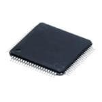
| 供应商器件封装 | 80-HTQFP(12x12) |
| 信噪比 | 70.5 dB |
| 其它名称 | 296-17153 |
| 分辨率 | 12 bit |
| 制造商产品页 | http://www.ti.com/general/docs/suppproductinfo.tsp?distId=10&orderablePartNumber=ADS5271IPFP |
| 包装 | 托盘 |
| 单位重量 | 368.100 mg |
| 商标 | Texas Instruments |
| 安装类型 | 表面贴装 |
| 安装风格 | SMD/SMT |
| 封装 | Tray |
| 封装/外壳 | 80-TQFP 裸露焊盘 |
| 封装/箱体 | HTQFP-80 |
| 工作温度 | -40°C ~ 85°C |
| 工作电源电压 | 3 V to 3.6 V |
| 工厂包装数量 | 96 |
| 接口类型 | Serial LVDS |
| 数据接口 | 串行 |
| 最大功率耗散 | 1000 mW |
| 最大工作温度 | + 85 C |
| 最小工作温度 | - 40 C |
| 标准包装 | 96 |
| 特性 | 同步采样 |
| 电压参考 | 1.95 V, 0.95 V |
| 电压源 | 模拟和数字 |
| 系列 | ADS5271 |
| 结构 | Pipeline |
| 转换器数 | 8 |
| 转换器数量 | 8 |
| 转换速率 | 50 MS/s |
| 输入数和类型 | 8 个差分,单极 |
| 输入类型 | Differential |
| 通道数量 | 8 Channel |
| 配用 | /product-detail/zh/ADSDESERADPT/296-30717-ND/1895963/product-detail/zh/ADSDESER-50EVM/ADSDESER-50EVM-ND/1689871/product-detail/zh/ADS5271EVM/296-17409-ND/696615 |
| 采样率(每秒) | 50M |


- 商务部:美国ITC正式对集成电路等产品启动337调查
- 曝三星4nm工艺存在良率问题 高通将骁龙8 Gen1或转产台积电
- 太阳诱电将投资9.5亿元在常州建新厂生产MLCC 预计2023年完工
- 英特尔发布欧洲新工厂建设计划 深化IDM 2.0 战略
- 台积电先进制程称霸业界 有大客户加持明年业绩稳了
- 达到5530亿美元!SIA预计今年全球半导体销售额将创下新高
- 英特尔拟将自动驾驶子公司Mobileye上市 估值或超500亿美元
- 三星加码芯片和SET,合并消费电子和移动部门,撤换高东真等 CEO
- 三星电子宣布重大人事变动 还合并消费电子和移动部门
- 海关总署:前11个月进口集成电路产品价值2.52万亿元 增长14.8%


PDF Datasheet 数据手册内容提取
ADS5271 ADS5271 www.ti.com...................................................................................................................................................... SBAS313C–JUNE2004–REVISEDJANUARY2009 8-Channel, 12-Bit, 50MSPS Analog-to-Digital Converter with Serial LVDS Interface FEATURES An integrated phase lock loop (PLL) multiplies the 1 • MaximumSampleRate:50MSPS incoming ADC sampling clock by a factor of 12. This 23 high-frequency LVDS clock is used in the data • 12-BitResolution serialization and transmission process. The word • NoMissingCodes output of each internal ADC is serialized and • TotalPowerDissipation: transmitted either MSB or LSB first. In addition to the eight data outputs, a bit clock and a word clock are InternalReference:927mW also transmitted. The bit clock is at 6x the speed of ExternalReference:861mW the sampling clock, whereas the word clock is at the • CMOSTechnology samespeedofthesamplingclock. • SimultaneousSample-and-Hold The ADS5271 provides internal references, or can • 70.5dBSNRat10MHzIF optionally be driven with external references. Best • 3.3VDigital/AnalogSupply performance is achieved through the internal referencemode. • SerializedLVDSOutputs • IntegratedFrameandBitPatterns The device is available in a TQFP-80 PowerPAD package and is specified over a –40°C to +85°C • OptiontoDoubleLVDSClockOutputCurrents operatingrange. • FourCurrentModesforLVDS • Pin-andFormat-CompatibleFamily 6xADCLK LCLKP • TQFP-80PowerPAD™Package 12xADCLK LCLKN PLL 1xADCLK ADCLKP APPLICATIONS ADCLK ADCLKN •• PTaoprteabDlreivUelstrasoundSystems IINN11NP S/H 1A2−DBCit Serializer OOUUTT11PN • TestEquipment IINN22NP S/H 1A2−DBCit Serializer OOUUTT22PN • OpticalNetworking IINN33NP S/H 1A2−DBCit Serializer OOUUTT33PN DESCRIPTION The ADS5271 is a high-performance, 50MSPS, IINN44NP S/H 1A2−DBCit Serializer OOUUTT44PN 8-channel analog-to-digital converter (ADC). Internal references are provided, simplifying system design IINN55NP S/H 1A2−DBCit Serializer OOUUTT55PN requirements. Low power consumption allows for the highest of system integration densities. Serial LVDS IINN66NP S/H 1A2−DBCit Serializer OOUUTT66PN (low-voltage differential signaling) outputs reduce the numberofinterfacelinesandpackagesize. IINN77NP S/H 1A2−DBCit Serializer OOUUTT77PN RELATEDPRODUCTS IINN88NP S/H 1A2−DBCit Serializer OOUUTT88PN RESOLUTION SAMPLE MODEL (BITS) RATE(MSPS) CHANNELS Reference Registers Control ADS5270 12 40 8 ADS5272 12 65 8 INT/EXT REFTVCMREFB CS SCLK SDATA RESET PD ADS5273 12 70 8 ADS5277 10 65 8 1 Pleasebeawarethatanimportantnoticeconcerningavailability,standardwarranty,anduseincriticalapplicationsofTexas Instrumentssemiconductorproductsanddisclaimerstheretoappearsattheendofthisdatasheet. PowerPADisatrademarkofTexasInstruments. 2 Allothertrademarksarethepropertyoftheirrespectiveowners. 3 PRODUCTIONDATAinformationiscurrentasofpublicationdate. Copyright©2004–2009,TexasInstrumentsIncorporated Products conform to specifications per the terms of the Texas Instruments standard warranty. Production processing does not necessarilyincludetestingofallparameters.
ADS5271 SBAS313C–JUNE2004–REVISEDJANUARY2009...................................................................................................................................................... www.ti.com This integrated circuit can be damaged by ESD. Texas Instruments recommends that all integrated circuits be handled with appropriateprecautions.Failuretoobserveproperhandlingandinstallationprocedurescancausedamage. ESDdamagecanrangefromsubtleperformancedegradationtocompletedevicefailure.Precisionintegratedcircuitsmaybemore susceptibletodamagebecauseverysmallparametricchangescouldcausethedevicenottomeetitspublishedspecifications. ORDERINGINFORMATION(1) SPECIFIED PACKAGE TEMPERATURE PACKAGE ORDERING TRANSPORT PRODUCT PACKAGE-LEAD(2) DESIGNATOR RANGE MARKING NUMBER MEDIA,QUANTITY ADS5271IPFP Tray,96 ADS5271 HTQFP-80 PFP –40°Cto+85°C ADS5271IPFP ADS5271IPFPT TapeandReel,250 (1) Forthemostcurrentpackageandorderinginformation,seethePackageOptionAddendumattheendofthisdocument,orseetheTI websiteatwww.ti.com. (2) Thermalpadsize:4.69mm×4.69mm(min),6.20mm×6.20mm(max). ABSOLUTE MAXIMUM RATINGS(1) SupplyVoltageRange,AVDD –0.3Vto+3.8V SupplyVoltageRange,LVDD –0.3Vto+3.8V VoltageBetweenAVSSandLVSS –0.3Vto+0.3V VoltageBetweenAVDDandLVDD –0.3Vto+0.3V VoltageAppliedtoExternalREFPins –0.3Vto+2.4V AllLVDSDataandClockOutputs –0.3Vto+2.4V AnalogInputPins(2) –0.3Vtomin.[3.3V,(AVDD+0.3V)] DigitalInputPins,Set1(pin69,76-78) –0.3Vtomin.[3.9V,(AVDD+0.3V)](3) DigitalInputPins,Set2(pins16,45) –0.3Vtomin.[3.9V,(LVDD+0.3V)](3) OperatingFree-AirTemperatureRange,T –40°Cto+85°C A LeadTemperature,1.6mm(1/16"fromcasefor10s) +260°C JunctionTemperature +105°C StorageTemperatureRange –65°Cto+150°C (1) Stressesabovetheseratingsmaycausepermanentdamage.Exposuretoabsolutemaximumconditionsforextendedperiodsmay degradedevicereliability.Thesearestressratingsonly,andfunctionaloperationofthedeviceattheseoranyotherconditionsbeyond thosespecifiedisnotsupported. (2) Thedcvoltageappliedontheinputpinsshouldnotgobelow–0.3V.Also,thedcvoltageshouldbelimitedtothelowerofeither3.3Vor (AVDD+0.3V).Iftheinputcangohigherthan+3.3V,thenaresistorgreaterthanorequalto25Ωshouldbeaddedinserieswitheach oftheinputpins.Also,thedutycycleoftheovershootbeyond+3.3Vshouldbelimited.Theovershootdutycyclecanbedefinedeither asapercentageofthetimeofovershootoveraclockperiod,orovertheentiredevicelifetime.Forapeakvoltagebetween+3.3Vand +3.5V,adutycycleupto10%isacceptable.Forapeakvoltagebetween+3.5Vand+3.7V,theovershootdutycycleshouldnotexceed 1%.Anyovershootbeyond+3.7Vshouldberestrictedtolessthan0.1%dutycycle,andneverexceed+3.9V. (3) Itisrecommendedtouseaseriesresistorof1kΩorgreaterifthedigitalinputpinsaretiedtoAVDDorLVDD. 2 SubmitDocumentationFeedback Copyright©2004–2009,TexasInstrumentsIncorporated ProductFolderLink(s):ADS5271
ADS5271 www.ti.com...................................................................................................................................................... SBAS313C–JUNE2004–REVISEDJANUARY2009 RECOMMENDED OPERATING CONDITIONS ADS5271 MIN TYP MAX UNITS SUPPLIESANDREFERENCES AnalogSupplyVoltage,AVDD 3.0 3.3 3.6 V OutputDriverSupplyVoltage,LVDD 3.0 3.3 3.6 V REF —ExternalReferenceMode 1.825 1.95 2.0 V T REF —ExternalReferenceMode 0.9 0.95 1.075 V B REFCM=(REF +REF )/2—ExternalReferenceMode(1) V ±50mV V T B CM Reference=(REF –REF )—ExternalReferenceMode 0.75 1.0 1.1 V T B AnalogInputCommon-ModeRange(1) V ±50mV V CM CLOCKINPUTANDOUTPUTS ADCLKInputSampleRate(low-voltageTTL) 20 50 MSPS ADCLKDutyCycle 45 55 % Low-LevelVoltageClockInput 0.6 V High-LevelVoltageClockInput 2.2 V ADCLK andADCLK Outputs(LVDS) 20 50 MHz P N LCLK andLCLK Outputs(LVDS)(2) 120 300 MHz P N OperatingFree-AirTemperature,T –40 +85 °C A ThermalCharacteristics: q 19.4 °C/W JA q 4.2 °C/W JC (1) Thesevoltagesneedtobesetto1.45V±50mViftheyarederivedindependentofV . CM (2) 6×ADCLK. Copyright©2004–2009,TexasInstrumentsIncorporated SubmitDocumentationFeedback 3 ProductFolderLink(s):ADS5271
ADS5271 SBAS313C–JUNE2004–REVISEDJANUARY2009...................................................................................................................................................... www.ti.com ELECTRICAL CHARACTERISTICS T =–40°CandT =+85°C.TypicalvaluesareatT =+25°C,clockfrequency=maximumspecified,50%clockduty MIN MAX A cycle,AVDD=3.3V,LVDD=3.3V,–1dBFS,I =56.2kΩ,internalvoltagereference,andLVDSbuffercurrentat3.5mAper SET channel,unlessotherwisenoted. ADS5271 PARAMETER TESTCONDITIONS MIN TYP MAX UNITS DCACCURACY NoMissingCodes Tested DNL DifferentialNonlinearity f =5MHz –0.9 ±0.5 +0.9 LSB IN INL IntegralNonlinearity f =5MHz –2.0 ±0.6 +2.0 LSB IN OffsetError(1) –0.75 +0.75 %FS OffsetTemperatureCoefficient ±6 ppm/°C FixedAttenuationinChannel(2) 1.5 %FS FixedAttenuationMatchingAcrossChannels 0.01 0.2 dB GainError/ReferenceError(3) VREF –VREF –2.5 ±1.0 +2.5 %FS T B GainErrorTemperatureCoefficient ±20 ppm/°C POWERREQUIREMENTS(4) InternalReference PowerDissipation AnalogOnly(AVDD) 743 792 mW OutputDriver(LVDD) 184 208 mW TotalPowerDissipation 927 1000 mW ExternalReference PowerDissipation AnalogOnly(AVDD) 677 mW OutputDriver(LVDD) 184 mW TotalPowerDissipation 861 mW Power-Down ClockRunning 92 149 mW REFERENCEVOLTAGES VREF ReferenceTop(internal) 1.9 1.95 2.0 V T VREF ReferenceBottom(internal) 0.9 0.95 1.0 V B V Common-ModeVoltage 1.4 1.45 1.5 V CM V OutputCurrent(5) ±50mVChangeinVoltage ±2.0 mA CM VREF ReferenceTop(external) 1.825 1.95 2.0 V T VREF ReferenceBottom(external) 0.9 0.95 1.075 V B ExternalReferenceCommon-Mode V ±50mV mV CM ExternalReferenceInputCurrent(6) 1.0 mA (1) Offseterroristhedeviationoftheaveragecodefrommid-codewith–1dBFSsinusoidfromidealmid-code(2048).Offseterroris expressedintermsof%offull-scale. (2) Fixedattenuationinthechannelarisesduetoafixedattenuationinthesample-and-holdamplifier.Whenthedifferentialvoltageatthe analoginputpinsarechangedfrom–V to+V ,theswingoftheoutputcodeisexpectedtodeviatefromthefull-scalecode REF REF (4096LSB)bytheextentofthisfixedattenuation.NOTE:V isdefinedas(REF –REF ). REF T B (3) Thereferencevoltagesaretrimmedatproductionsothat(VREF –VREF )iswithin±25mVoftheidealvalueof1V.Thisspecification T B doesnotincludefixedattenuation. (4) Supplycurrentcanbecalculatedfromdividingthepowerdissipationbythesupplyvoltageof3.3V. (5) V providesthecommon-modecurrentfortheinputsofalleightchannelswhentheinputsareac-coupled.TheV outputcurrent CM CM specifiedistheadditionaldriveoftheV bufferifloadedexternally. CM (6) Averagecurrentdrawnfromthereferencepinsintheexternalreferencemode. 4 SubmitDocumentationFeedback Copyright©2004–2009,TexasInstrumentsIncorporated ProductFolderLink(s):ADS5271
ADS5271 www.ti.com...................................................................................................................................................... SBAS313C–JUNE2004–REVISEDJANUARY2009 ELECTRICAL CHARACTERISTICS (continued) T =–40°CandT =+85°C.TypicalvaluesareatT =+25°C,clockfrequency=maximumspecified,50%clockduty MIN MAX A cycle,AVDD=3.3V,LVDD=3.3V,–1dBFS,I =56.2kΩ,internalvoltagereference,andLVDSbuffercurrentat3.5mAper SET channel,unlessotherwisenoted. ADS5271 PARAMETER TESTCONDITIONS MIN TYP MAX UNITS ANALOGINPUT DifferentialInputCapacitance 4.0 pF AnalogInputCommon-ModeRange V ±50mV mV CM DifferentialFull-ScaleInputVoltageRange InternalReference 2.03 V PP ExternalReference 2.03×(VREF –VREF ) V T B PP VoltageOverheadRecoveryTime(7) 3.0 CLKCycles –3dBFS,25ΩSeries InputBandwidth 300 MHz Resistances DIGITALDATAINPUTS V High-LevelInputVoltage 2.2 V IH V Low-LevelInputVoltage 0.6 V IL C InputCapacitance 3.0 pF IN DIGITALDATAOUTPUTS DataFormat StraightOffsetBinary DataBitRate 240 600 Mbps SERIALINTERFACE SCLK SerialClockInputFrequency 20 MHz (7) AdifferentialON/OFFpulseisappliedtotheADCinput.ThedifferentialamplitudeofthepulseinitsON(high)stateistwicethe full-scalerangeoftheADC,whilethedifferentialamplitudeofthepulseinitsOFF(low)stateiszero.Theoverloadrecoverytimeofthe ADCismeasuredasthetimerequiredbytheADCoutputcodetosettlewithin1%offull-scale,asmeasuredfromitsmid-codevalue whenthepulseisswitchedfromON(high)toOFF(low). REFERENCESELECTION MODE INT/EXT DESCRIPTION InternalReference;FSR=2.03V 1 Defaultwithinternalpull-up. PP Internalreferenceispowereddown.Thecommon-modevoltage ExternalReference;FSR=2.03x(REF –REF ) 0 oftheexternalreferenceshouldbewithin50mVofV .V is T B CM CM derivedfromtheinternalbandgapvoltage. Copyright©2004–2009,TexasInstrumentsIncorporated SubmitDocumentationFeedback 5 ProductFolderLink(s):ADS5271
ADS5271 SBAS313C–JUNE2004–REVISEDJANUARY2009...................................................................................................................................................... www.ti.com AC CHARACTERISTICS T =–40°CandT =+85°C.TypicalvaluesareatT =+25°C,clockfrequency=maximumspecified,50%clockduty MIN MAX A cycle,AVDD=3.3V,LVDD=3.3V,–1dBFS,I =56.2kΩ,internalvoltagereference,andLVDSbuffercurrentat3.5mAper SET channel,unlessotherwisenoted. ADS5271 PARAMETER CONDITIONS MIN TYP MAX UNITS DYNAMICCHARACTERISTICS fIN=1MHz 87 dBc fIN=5MHz 78 85 dBc SFDR Spurious-FreeDynamicRange fIN=10MHz 84 dBc fIN=20MHz 82 dBc fIN=1MHz 90 dBc fIN=5MHz 85 90 dBc HD2 2nd-OrderHarmonicDistortion fIN=10MHz 87 dBc fIN=20MHz 85 dBc fIN=1MHz 87 dBc fIN=5MHz 78 85 dBc HD3 3rd-OrderHarmonicDistortion fIN=10MHz 84 dBc fIN=20MHz 82 dBc fIN=1MHz 70.5 dBFS fIN=5MHz 69.5 70.5 dBFS SNR Signal-to-NoiseRatio fIN=10MHz 70.5 dBFS fIN=20MHz 70.5 dBFS fIN=1MHz 70 dBFS fIN=5MHz 69 70 dBFS SINAD Signal-to-NoiseandDistortion fIN=10MHz 70 dBFS fIN=20MHz 70 dBFS ENOB EffectiveNumberofBits fIN=5MHz 11.3 Bits 5MHzFull-ScaleSignalAppliedto7Channels; –90 dBc Crosstalk MeasurementTakenontheChannelwithNoInputSignal IMD3 Two-Tone,Third-Order f1=9.5MHzat–7dBFS –85 dBFS IntermodulationDistortion f2=10.2MHzat–7dBFS 6 SubmitDocumentationFeedback Copyright©2004–2009,TexasInstrumentsIncorporated ProductFolderLink(s):ADS5271
ADS5271 www.ti.com...................................................................................................................................................... SBAS313C–JUNE2004–REVISEDJANUARY2009 LVDS DIGITAL DATA AND CLOCK OUTPUTS TestconditionsatI =3.5mA,R =100Ω,C =6pF,and50%dutycycle.I referstothecurrentsettingfortheLVDSbuffer.R is O LOAD LOAD O LOAD thedifferentialloadresistancebetweenthedifferentialLVDSpair.C istheeffectivesingle-endedloadcapacitancebetweeneachofthe LOAD LVDSpinsandground.C includesthereceiverinputparasiticsaswellastheroutingparasitics.Measurementsaredonewitha1-inch LOAD transmissionlineof100Ωcharacteristicimpedancebetweenthedeviceandtheload.AllLVDSspecificationsarecharacterized,butnot parametricallytestedatproduction.LCLKOUTrefersto(LCLK –LCLK );ADCLKOUTrefersto(ADCLK –ADCLK );DATAOUTrefersto P N P N (OUT –OUT );andADCLKreferstotheinputsamplingclock. P N PARAMETER CONDITIONS MIN TYP MAX UNITS DCSPECIFICATIONS(1) VOH OutputVoltageHigh,OUTPorOUTN RLOAD=100Ω ±1%;SeeLVDSTimingDiagram,Page8 1265 1365 1465 mV VOL OutputVoltageLow,OUTPorOUTN RLOAD=100Ω ±1% 940 1040 1140 mV |VOD| OutputDifferentialVoltage RLOAD=100Ω ±1% 275 325 375 mV VOS OutputOffsetVoltage(2) RLOAD=100Ω ±1%;SeeLVDSTimingDiagram,Page8 1.1 1.2 1.3 V RO OutputImpedance,Differential NormalOperation 13 kΩ RO OutputImpedance,Differential Power-Down 20 kΩ CO OutputCapacitance(3) 4 pF |ΔVOD| Changein|VOD|Between0and1 RLOAD=100Ω ±1% 10 mV ΔVOS ChangeBetween0and1 RLOAD=100Ω ±1% 25 mV ISOUT OutputShort-CircuitCurrent DriversShortedtoGround 40 mA ISOUTNP OutputCurrent DriversShortedTogether 12 mA DRIVERACSPECIFICATIONS ADCLKOUTClockDutyCycle(4) 45 50 55 % LCLKOUTDutyCycle(4) 45 50 55 % DataSetupTime(5)(6) 0.6 ns DataHoldTime(6)(7) 0.42 ns LVDSOutputsRise/FallTime(8) IO=2.5mA 400 ps IO=3.5mA 180 300 500 ps IO=4.5mA 230 ps IO=6.0mA 180 ps LCLKOUTRisingEdgetoADCLKOUTRisingEdge(9) 0.60 0.83 1.05 ns ADCLKOUTRisingEdgetoLCLKOUTFallingEdge(9) 0.60 0.83 1.05 ns ADCLKOUTRisingEdgetoDATAOUTTransition(9) –0.35 0 +0.35 ns (1) ThedcspecificationsrefertotheconditionwheretheLVDSoutputsarenotswitching,butarepermanentlyatavalidlogiclevel0or1. (2) V referstothecommon-modeofOUT andOUT . OS P N (3) Outputcapacitanceinsidethedevice,fromeitherOUT orOUT toground. P N (4) Measuredbetweenzerocrossings. (5) DATAOUT(OUT –OUT )crossingzerotoLCLKOUT(LCLK –LCLK )crossingzero. P N P N (6) Datasetupandholdtimeaccountsfordata-dependentskews,channel-to-channelmismatches,aswellaseffectsofclockjitterwithin thedevice. (7) LCLKOUTcrossingzerotoDATAOUTcrossingzero. (8) Measuredfrom–100mVto+100mVonthedifferentialoutputforrisetime,and+100mVto–100mVforfalltime. (9) Measuredbetweenzerocrossings. SWITCHING CHARACTERISTICS T =–40°CandT =+85°C.TypicalvaluesareatT =+25°C,clockfrequency=maximumspecified,50%clockduty MIN MAX A cycle,AVDD=3.3V,LVDD=3.3V,–1dBFS,internalvoltagereference,andLVDSbuffercurrentat3.5mAperchannel, unlessotherwisenoted. PARAMETER CONDITIONS MIN TYP MAX UNITS SWITCHINGSPECIFICATIONS t 20 50 ns SAMPLE t (A) ApertureDelay 2 4 6.5 ns D ApertureJitter(uncertainty) 1 psrms t (pipeline) Latency 6.5 Cycles D t PropagationDelay 3 4.8 6.5 ns PROP Copyright©2004–2009,TexasInstrumentsIncorporated SubmitDocumentationFeedback 7 ProductFolderLink(s):ADS5271
ADS5271 SBAS313C–JUNE2004–REVISEDJANUARY2009...................................................................................................................................................... www.ti.com LVDSTIMINGDIAGRAM(PERADCCHANNEL) Samplen Samplen+6 Input 1 t SAMPLE ADCLK t S 2 LCLK P 6XADCLK LCLK N OUT P SERIALDATA D0 D1 D2 D3 D4 D5 D6 D7 D8 D9 D10 D11 D0 D1 D2 D3 D4 D5 D6 D7 D8 D9 D10D11 D0 D1 OUT N Samplendata ADCLK P 1XADCLK ADCLK N t (A) t D PROP 6.5ClockCycles NOTE:SerialdatabitformatshowninLSBfirstmode. RECOMMENDEDPOWER-UPSEQUENCINGANDRESETTIMING AVDD(3Vto3.6V) t 1 AVDD t LVDD(3Vto3.6V) 2 LVDD DeviceReady t3 t4 t7 ForADCOperation t t 5 6 RESET DeviceReady ForSerialRegisterWrite CS DeviceReady StartofClock ForADCOperation ADCLK t 8 NOTE:10m s<t <50ms;10m s<t <50ms;- 10ms<t <10ms;t >10ms;t >100ns;t >100ns;t >10ms;andt >100m s. 1 2 3 4 5 6 7 8 8 SubmitDocumentationFeedback Copyright©2004–2009,TexasInstrumentsIncorporated ProductFolderLink(s):ADS5271
ADS5271 www.ti.com...................................................................................................................................................... SBAS313C–JUNE2004–REVISEDJANUARY2009 POWER-DOWNTIMING 1m s 500m s PD DeviceFully PowersDown DeviceFully PowersUp NOTE:Theshownpower−uptimeisbasedon1m Fbypasscapacitorsonthereferencepins. SeetheTheoryofOperationsectionfordetails. SERIAL INTERFACE TIMING Outputschangeon nextrisingclockedge afterCSgoeshigh. ADCLK CS StartSequence t t 6 1 t Datalatchedon 7 t 2 eachrisingedgeofSCLK. SCLK t 3 D7 SDATA D6 D5 D4 D3 D2 D1 D0 (MSB) t 4 t 5 NOTE:DataisshiftedinMSBfirst. PARAMETER DESCRIPTION MIN TYP MAX UNIT t SerialCLKPeriod 50 ns 1 t SerialSLKHighTime 20 ns 2 t SerialCLKLowTime 20 ns 3 t DataSetupTime 5 ns 4 t DataHoldTime 5 ns 5 t CSFalltoSCLKRise 8 ns 6 t SCLKRisetoCSRise 8 ns 7 Copyright©2004–2009,TexasInstrumentsIncorporated SubmitDocumentationFeedback 9 ProductFolderLink(s):ADS5271
ADS5271 SBAS313C–JUNE2004–REVISEDJANUARY2009...................................................................................................................................................... www.ti.com SERIALINTERFACEREGISTERS ADDRESS DATA DESCRIPTION REMARKS D7 D6 D5 D4 D3 D2 D1 D0 0 0 0 0 LVDSBUFFERS(Register0) AllDataOutputs 0 0 NormalADCOutput (defaultafterreset) 0 1 DeskewPattern 1 0 SyncPattern SeeTestPatterns 1 1 CustomPattern 0 0 OutputCurrentinLVDS=3.5mA (defaultafterreset) 0 1 OutputCurrentinLVDS=2.5mA 1 0 OutputCurrentinLVDS=4.5mA 1 1 OutputCurrentinLVDS=6.0mA 0 0 0 1 CLOCKCURRENT(Register1) 0 X X 0 DefaultLVDSClockOutputCurrent I =3.5mA(default) OUT 0 X X 1 2xLVDSClockOutputCurrent(1) I =7.0mA OUT 0 0 0 1 LSB/MSBMODE(Register1) 0 0 X X LSBFirstMode (defaultafterreset) 0 1 X X MSBFirstMode 0 0 1 0 POWER-DOWNADCCHANNELS (Register2) X X X X Example:1010PowersDown Power-DownChannels1to4;D3is Channels4and2and forChannel4andD0forChannel1 KeepsChannels1and3Active 0 0 1 1 POWER-DOWNADCCHANNELS (Register3) X X X X Power-DownChannels5to8;D3is forChannel8andD0forChannel5 CUSTOMPATTERN(Registers4–6) D3 D2 D1 D0 BitsforCustomPattern SeeTestPatterns 0 1 0 0 X X X X 0 1 0 1 X X X X 0 1 1 0 X X X X (1) OutputcurrentdriveforthetwoclockLVDSbuffers(LCLK andLCLK andADCLK andADCLK )isdoubletheoutputcurrentsetting P N P N programmedinregister0.Thecurrentdriveofthedatabuffersremainsthesameasthesettinginregister0. TEST PATTERNS SerialOutput(1) LSB MSB ADCOutput(2) D0 D1 D2 D3 D4 D5 D6 D7 D8 D9 D10 D11 DeskewPattern 1 0 1 0 1 0 1 0 1 0 1 0 SyncPattern 0 0 0 0 0 0 1 1 1 1 1 1 CustomPattern(3) D0(4) D1(4) D2(4) D3(4) D0(5) D1(5) D2(5) D3(5) D0(6) D1(6) D2(6) D3(6) (1) TheserialoutputstreamcomesoutLSBfirstbydefault. (2) D11...D0representthe12outputbitsfromtheADC. (3) D0(4)representsthecontentofbitD0ofregister4,D3(6)representsthecontentofbitD3ofregister6,etc. 10 SubmitDocumentationFeedback Copyright©2004–2009,TexasInstrumentsIncorporated ProductFolderLink(s):ADS5271
ADS5271 www.ti.com...................................................................................................................................................... SBAS313C–JUNE2004–REVISEDJANUARY2009 PIN CONFIGURATION Top View HTQFP T AVSS AVSS SCLK SDATA CS AVDD AVSS AVSS AVSS ADCLK AVDD INT/EX AVSS REFT REFB VCM ISET AVDD AVSS AVSS 80 79 78 77 76 75 74 73 72 71 70 69 68 67 66 65 64 63 62 61 AVDD 1 60 AVDD IN1 2 59 IN8 P N IN1 3 58 IN8 N P AVSS 4 57 AVSS IN2 5 56 IN7 P N IN2 6 55 IN7 N P AVDD 7 54 AVDD AVSS 8 53 AVSS IN3 9 52 IN6 P N IN3 10 51 IN6 N P ADS5271 AVSS 11 50 AVSS IN4 12 49 IN5 P N IN4 13 48 IN5 N P AVDD 14 47 AVDD LVSS 15 46 LVSS PD 16 45 RESET LVSS 17 44 LVSS LVSS 18 43 LVSS LCLK 19 42 ADCLK P N LCLK 20 41 ADCLK N P 21 22 23 24 25 26 27 28 29 30 31 32 33 34 35 36 37 38 39 40 P N P N D S P N P N P N P N D S P N P N OUT1 OUT1 OUT2 OUT2 LVD LVS OUT3 OUT3 OUT4 OUT4 OUT5 OUT5 OUT6 OUT6 LVD LVS OUT7 OUT7 OUT8 OUT8 Copyright©2004–2009,TexasInstrumentsIncorporated SubmitDocumentationFeedback 11 ProductFolderLink(s):ADS5271
ADS5271 SBAS313C–JUNE2004–REVISEDJANUARY2009...................................................................................................................................................... www.ti.com PINDESCRIPTIONS NAME PIN# I/O DESCRIPTION ADCLK 71 I DataConverterClockInput ADCLKN 42 O NegativeLVDSADCClockOutput ADCLKP 41 O PositiveLVDSADCClockOutput AVDD 1,7,14,47,54,60,63,70,75 I AnalogPowerSupply AVSS 4,8,11,50,53,57,61,62,68,72–74,79,80 I AnalogGround CS 76 I ChipSelect;0=Select,1=NoSelect IN1N 3 I Channel1DifferentialAnalogInputLow IN1P 2 I Channel1DifferentialAnalogInputHigh IN2N 6 I Channel2DifferentialAnalogInputLow IN2P 5 I Channel2DifferentialAnalogInputHigh IN3N 10 I Channel3DifferentialAnalogInputLow IN3P 9 I Channel3DifferentialAnalogInputHigh IN4N 13 I Channel4DifferentialAnalogInputLow IN4P 12 I Channel4DifferentialAnalogInputHigh IN5N 49 I Channel5DifferentialAnalogInputLow IN5P 48 I Channel5DifferentialAnalogInputHigh IN6N 52 I Channel6DifferentialAnalogInputLow IN6P 51 I Channel6DifferentialAnalogInputHigh IN7N 56 I Channel7DifferentialAnalogInputLow IN7P 55 I Channel7DifferentialAnalogInputHigh IN8N 59 I Channel8DifferentialAnalogInputLow IN8P 58 I Channel8DifferentialAnalogInputHigh INT/EXT 69 I Internal/ExternalReferenceSelect;0=External,1=Internal.Weakpull-uptosupply. ISET 64 I/O BiasCurrentSettingResistorof56.2kΩtoGround LCLKN 20 O NegativeLVDSClock LCLKP 19 O PositiveLVDSClock LVDD 25,35 I LVDSPowerSupply LVSS 15,17,18,26,36,43,44,46 I LVDSGround OUT1N 22 O Channel1NegativeLVDSDataOutput OUT1P 21 O Channel1PositiveLVDSDataOutput OUT2N 24 O Channel2NegativeLVDSDataOutput OUT2P 23 O Channel2PositiveLVDSDataOutput OUT3N 28 O Channel3NegativeLVDSDataOutput OUT3P 27 O Channel3PositiveLVDSDataOutput OUT4N 30 O Channel4NegativeLVDSDataOutput OUT4P 29 O Channel4PositiveLVDSDataOutput OUT5N 32 O Channel5NegativeLVDSDataOutput OUT5P 31 O Channel5PositiveLVDSDataOutput OUT6N 34 O Channel6NegativeLVDSDataOutput OUT6P 33 O Channel6PositiveLVDSDataOutput OUT7N 38 O Channel7NegativeLVDSDataOutput OUT7P 37 O Channel7PositiveLVDSDataOutput OUT8N 40 O Channel8NegativeLVDSDataOutput OUT8P 39 O Channel8PositiveLVDSDataOutput PD 16 I Power-Down;0=Normal,1=Power-Down REFB 66 I/O ReferenceBottomVoltage(2Ωresistorinserieswitha0.1Fcapacitortoground) REFT 67 I/O ReferenceTopVoltage(2Ωresistorinserieswitha0.1Fcapacitortoground) RESET 45 I ResettoDefault;0=Reset,1=Normal.Weakpull-downtoground. SCLK 78 I SerialDataClock SDATA 77 I SerialDataInput VCM 65 O Common-ModeOutputVoltage 12 SubmitDocumentationFeedback Copyright©2004–2009,TexasInstrumentsIncorporated ProductFolderLink(s):ADS5271
ADS5271 www.ti.com...................................................................................................................................................... SBAS313C–JUNE2004–REVISEDJANUARY2009 DEFINITION OF SPECIFICATIONS Analog Bandwidth Minimum Conversion Rate The analog input frequency at which the spectral This is the minimum sampling rate where the ADC power of the fundamental frequency (as determined stillworks. byFFTanalysis)isreducedby3dB. Signal-to-Noise and Distortion (SINAD) Aperture Delay SINAD is the ratio of the power of the fundamental Thedelayintimebetweentherising edge of the input (P ) to the power of all the other spectral components S sampling clock and the actual time at which the including noise (P ) and distortion (P ), but not N D samplingoccurs. includingdc. P Aperture Uncertainty (Jitter) SINAD(cid:2)10Log10P (cid:1)SP N D Thesample-to-samplevariationinaperturedelay. SINAD is either given in units of dBc (dB to carrier) when the absolute power of the fundamental is used Clock Duty Cycle as the reference, or dBFS (dB to full-scale) when the Pulse width high is the minimum amount of time that power of the fundamental is extrapolated to the the ADCLK pulse should be left in logic ‘1’ state to full-scalerangeoftheconverter. achieve rated performance. Pulse width low is the minimum time that the ADCLK pulse should be left in Signal-to-Noise Ratio (SNR) a low state (logic ‘0’). At a given clock rate, these SNR is the ratio of the power of the fundamental (P ) specificationsdefineanacceptableclockdutycycle. S to the noise floor power (P ), excluding the power at N dcandthefirsteightharmonics. Differential Nonlinearity (DNL) P An ideal ADC exhibits code transitions that are SNR(cid:1)10Log S 10P exactly 1 LSB apart. DNL is the deviation of any N single LSB transition at the digital output from an SNR is either given in units of dBc (dB to carrier) ideal 1 LSB step at the analog input. If a device when the absolute power of the fundamental is used claims to have no missing codes, it means that all as the reference, or dBFS (dB to full-scale) when the possible codes (for a 12-bit converter, 4096 codes) power of the fundamental is extrapolated to the arepresentoverthefulloperatingrange. full-scalerangeoftheconverter. Effective Number of Bits (ENOB) Spurious-Free Dynamic Range The ENOB is a measure of converter performance as The ratio of the power of the fundamental to the compared to the theoretical limit based on highest other spectral component (either spur or quantizationnoise. harmonic). SFDR is typically given in units of dBc (dB ENOB(cid:2)SINAD(cid:1)1.76 tocarrier). 6.02 Two-Tone, Third-Order Intermodulation Integral Nonlinearity (INL) Distortion INL is the deviation of the transfer function from a Two-tone IMD3 is the ratio of power of the reference line measured in fractions of 1 LSB using a fundamental (at frequencies f and f ) to the power of 1 2 best straight line or best fit determined by a least the worst spectral component of third-order square curve fit. INL is independent from effects of intermodulation distortion at either frequency 2f – f 1 2 offset,gainorquantizationerrors. or 2f – f . IMD3 is either given in units of dBc (dB to 2 1 carrier) when the absolute power of the fundamental Maximum Conversion Rate is used as the reference, or dBFS (dB to full-scale) when the power of the fundamental is extrapolated to The encode rate at which parametric testing is thefull-scalerangeoftheconverter. performed. This is the maximum sampling rate where certifiedoperationisgiven. Copyright©2004–2009,TexasInstrumentsIncorporated SubmitDocumentationFeedback 13 ProductFolderLink(s):ADS5271
ADS5271 SBAS313C–JUNE2004–REVISEDJANUARY2009...................................................................................................................................................... www.ti.com TYPICAL CHARACTERISTICS TypicalvaluesareatT =+25C,clockfrequency=maximumspecified,50%clockdutycycle,AVDD=3.3V,LVDD=3.3V, A –1dBFS,I =56.2kΩ,internalvoltagereference,andLVDSbuffercurrentat3.5mAperchannel,unlessotherwisenoted. SET SPECTRALPERFORMANCE SPECTRALPERFORMANCE 0 0 f =1MHz(- 1dBFS) f =5MHz(- 1dBFS) IN IN SNR=71.1dBFS SNR=70.9dBFS - 20 SINAD=70.9dBFS - 20 SINAD=70.8dBFS SFDR=87.7dBc SFDR=89dBc B) - 40 B) - 40 d d ( ( e e ud - 60 ud - 60 plit plit m m A - 80 A - 80 - 100 - 100 - 120 - 120 0 5 10 15 20 25 0 5 10 15 20 25 InputFrequency(MHz) InputFrequency(MHz) Figure1. Figure2. SPECTRALPERFORMANCE SPECTRALPERFORMANCE 0 0 f =10MHz(- 1dBFS) f =20MHz(- 1dBFS) IN IN SNR=70.9dBFS SNR=70.5dBFS - 20 SINAD=70.7dBFS - 20 SINAD=70.4dBFS SFDR=85.4dBc SFDR=85.6dBc B) - 40 B) - 40 d d ( ( e e ud - 60 ud - 60 plit plit m m A - 80 A - 80 - 100 - 100 - 120 - 120 0 5 10 15 20 25 0 5 10 15 20 25 InputFrequency(MHz) InputFrequency(MHz) Figure3. Figure4. INTERMODULATIONDISTORTION DIFFERENTIALNONLINEARITY 0 0.5 f =5MHz f1=9.5MHz(- 7dBFS) 0.4 IN - 20 f =10.2MHz(- 7dBFS) 2 IMD=- 85dBFS 0.3 B) - 40 0.2 ude(d - 60 (LSB) 0.10 mplit DNL - 0.1 A - 80 - 0.2 - 100 - 0.3 - 0.4 - 120 - 0.5 0 5 10 15 20 25 0 512 1024 1536 2048 2560 3072 3584 4096 InputFrequency(MHz) Code Figure5. Figure6. 14 SubmitDocumentationFeedback Copyright©2004–2009,TexasInstrumentsIncorporated ProductFolderLink(s):ADS5271
ADS5271 www.ti.com...................................................................................................................................................... SBAS313C–JUNE2004–REVISEDJANUARY2009 TYPICAL CHARACTERISTICS (continued) TypicalvaluesareatT =+25C,clockfrequency=maximumspecified,50%clockdutycycle,AVDD=3.3V,LVDD=3.3V, A –1dBFS,I =56.2kΩ,internalvoltagereference,andLVDSbuffercurrentat3.5mAperchannel,unlessotherwisenoted. SET INTEGRALNONLINEARITY SWEPTINPUTPOWER 1.0 90 f =5MHz f =5MHz IN IN 0.8 80 SNR(dBFS) 0.6 S) 70 F 0.4 B d 60 SB) 0.2 dBc, 50 SFDR(dBc) (L 0 R( INL - 0.2 SN 40 SNR(dBc) - 0.4 DR, 30 F - 0.6 S 20 - 0.8 10 - 1.0 0 0 512 1024 1536 2048 2560 3072 3584 4096 - 70 - 60 - 50 - 40 - 30 - 20 - 10 0 Code InputAmplitude(dBFS) Figure7. Figure8. SWEPTINPUTPOWER DYNAMICPERFORMANCEvsDUTYCYCLE 90 95 f =10MHz f =5MHz IN IN 80 90 S) 70 SNR(dBFS) FS) SFDR BF dB 85 d 60 ( NR(dBc, 5400 SFDR(dBc) R,SINAD 8705 DR,S 30 SNR(dBc) R,SN 70 SNR F D S 20 F SINAD S 65 10 0 60 - 70 - 60 - 50 - 40 - 30 - 20 - 10 0 20 30 40 50 60 70 80 InputAmplitude(dBFS) DutyCycle(%) Figure9. Figure10. DYNAMICPERFORMANCEvsINPUTFREQUENCY DYNAMICPERFORMANCEvsSAMPLERATE 95 95 f =5MHz IN 90 90 SFDR FS) 85 SFDR S) 85 dB F ( 80 B D d A NR( 80 SIN 75 SNR S 75 R, 70 SFDR, 70 SNR DR,SN 65 SINAD F 60 S 65 55 60 50 0 5 10 15 20 25 30 35 40 45 50 15 20 25 30 35 40 45 50 55 60 InputFrequency(MHz) SampleRate(MSPS) Figure11. Figure12. Copyright©2004–2009,TexasInstrumentsIncorporated SubmitDocumentationFeedback 15 ProductFolderLink(s):ADS5271
ADS5271 SBAS313C–JUNE2004–REVISEDJANUARY2009...................................................................................................................................................... www.ti.com TYPICAL CHARACTERISTICS (continued) TypicalvaluesareatT =+25C,clockfrequency=maximumspecified,50%clockdutycycle,AVDD=3.3V,LVDD=3.3V, A –1dBFS,I =56.2kΩ,internalvoltagereference,andLVDSbuffercurrentat3.5mAperchannel,unlessotherwisenoted. SET DYNAMICPERFORMANCEvsSAMPLERATE SUPPLYCURRENTvsSAMPLERATE 95 300 f =10MHz IN 90 S) SFDR 250 F 85 IAVDD B d ( 80 200 AD A) N 75 m R,SI 70 SNR ent( 150 R,SN 65 SINAD Curr 100 FD 60 ILVDD S 50 55 50 0 15 20 25 30 35 40 45 50 55 60 10 15 20 25 30 35 40 45 50 SampleRate(MSPS) SampleRate(MSPS) Figure13. Figure14. 16 SubmitDocumentationFeedback Copyright©2004–2009,TexasInstrumentsIncorporated ProductFolderLink(s):ADS5271
ADS5271 www.ti.com...................................................................................................................................................... SBAS313C–JUNE2004–REVISEDJANUARY2009 THEORY OF OPERATION data externally has multiple advantages, such as a OVERVIEW reduced number of output pins (saving routing space on the board), reduced power consumption, and The ADS5271 is an 8-channel, high-speed, CMOS reduced effects of digital noise coupling to the analog ADC. It consists of a high-performance circuitinsidetheADS5271. sample-and-hold circuit at the input, followed by a 12-bit ADC. The 12 bits given out by each channel The ADS5271 operates from two sets of supplies and are serialized and sent out on a single pair of pins in grounds. The analog supply/ground set is denoted as LVDS format. All eight channels of the ADS5271 AVDD/AVSS, while the digital set is denoted by operate from a single clock referred to as ADCLK. LVDD/LVSS. The sampling clocks for each of the eight channels are generated from the input clock using a carefully DRIVING THE ANALOG INPUTS matched clock buffer tree. The 12x clock required for The analog input biasing is shown in Figure 15. The the serializer is generated internally from ADCLK inputs are biased internally using two 600Ω resistors using a phase lock loop (PLL). A 6x and a 1x clock to enable ac-coupling. A resistor greater than 20Ω is are also output in LVDS format along with the data to recommendedinserieswitheachinputpin. enable easy data capture. The ADS5271 operates from internally generated reference voltages that are A 4pF sampling capacitor is used to sample the trimmed to ensure matching across multiple devices inputs. The choice of the external ac-coupling on a board. This feature eliminates the need for capacitor is dictated by the attenuation at the lowest external routing of reference lines and also improves desired input frequency of operation. The attenuation matching of the gain across devices. The nominal resulting from using a 10nF ac-coupling capacitor is values of REF and REF are 1.95V and 0.95V, 0.04%. T B respectively. These values imply that a differential input of –1V corresponds to the zero code of the ADC, and a differential input of +1V corresponds to ADS5271 the full-scale code (4095 LSB). V (common-mode IN+ CM voltage of REFT and REFB) is also made available 600W externallythroughapin,andisnominally1.45V. Input Circuitry The ADC employs a pipelined converter architecture 600W consisting of a combination of multi-bit and single-bit IN- internal stages. Each stage feeds its data into the digital error correction logic, ensuring excellent Internal differential linearity and no missing codes at the VCM Voltage 12-bit level. The pipeline architecture results in a data CMBuffer Reference latencyof6.5clockcycles. The output of the ADC goes to a serializer that NOTE:Dashedareadenotesoneofeightchannels. operates from a 12x clock generated by the PLL. The 12 data bits from each channel are serialized and Figure15.AnalogInputBiasCircuitry sent LSB first. In addition to serializing the data, the serializer also generates a 1x clock and a 6x clock. If the input is dc-coupled, then the output These clocks are generated in the same way the common-mode voltage of the circuit driving the serialized data is generated, so these clocks maintain ADS5271shouldmatchtheV (whichisprovidedas perfect synchronization with the data. The data and CM an output pin) to within ±50mV. It is recommended clock outputs of the serializer are buffered externally that the output common-mode of the driving circuit be using LVDS buffers. Using LVDS buffers to transmit derivedfromV providedbythedevice. CM Copyright©2004–2009,TexasInstrumentsIncorporated SubmitDocumentationFeedback 17 ProductFolderLink(s):ADS5271
ADS5271 SBAS313C–JUNE2004–REVISEDJANUARY2009...................................................................................................................................................... www.ti.com Figure 16 shows a detailed RLC model of the over-voltage pulse input of twice the amplitude of a sample-and-hold circuit. The circuit operates in two full-scale pulse is expected to be within three clock phases. In the sample phase, the input is sampled on cycles when the input switches from overload to zero two capacitors that are nominally 4pF. The sampling signal. All of the amplifiers in the SHA and ADC are circuit consists of a low-pass RC filter at the input to specially designed for excellent recovery from an filter out noise components that might be differentially overloadsignal. coupled on the input pins. The next phase is the hold In most applications, the ADC inputs are driven with phase wherein the voltage sampled on the capacitors differential sinusoidal inputs. While the pulse-type is transferred (using the amplifier) to a subsequent signal remains at peak overload conditions pipelineADCstage. throughout its HIGH state, the sinusoid signal only attains peak overload intermittently, at its minima and INPUT OVER-VOLTAGE RECOVERY maxima. This condition is much less severe for the The differential full-scale range supported by the ADC input and the recovery of the ADC output (to 1% ADS5271 is nominally 2.03V. The ADS5271 is of full-scale around the expected code). This typically specially designed to handle an over-voltage happens within the second clock when the input is condition where the differential peak-to-peak voltage driven with a sinusoid of amplitude equal to twice that can exceed up to twice the ADC full-scale range. If oftheADCdifferentialfull-scalerange. the input common-mode is not considerably off from V during overload (less than 300mV around the CM nominal value of 1.45V), recovery from an IN OUT 5nH to9nH IN P 1.5pFto 2.5pF 15W 15W 3.2pF 60W to25W to25W to4.8pF to120W 1W IN OUT IN OUT 500W to720W OUT OUT P 1.5pF to1.9pF IN OUT 500W N to720W 15W to35W 15W 15W 3.2pF 60W to25W to25W to4.8pF to120W IN OUT IN OUT 5nH to9nH IN N 1.5pFto SwitchesthatareON 2.5pF inSAMPLEphase. 1W SwitchesthatareON inHOLDphase. IN OUT Figure16.OverallStructureoftheSample-and-HoldCircuit 18 SubmitDocumentationFeedback Copyright©2004–2009,TexasInstrumentsIncorporated ProductFolderLink(s):ADS5271
ADS5271 www.ti.com...................................................................................................................................................... SBAS313C–JUNE2004–REVISEDJANUARY2009 REFERENCE CIRCUIT DESIGN The device also supports the use of external reference voltages. This mode involves forcing REF The digital beam-forming algorithm relies heavily on T and REF externally. In this mode, the internal gain matching across all receiver channels. A typical B reference buffer is tri-stated. Since the switching system would have about 12 octal ADCs on the current for the eight ADCs come from the externally board. In such a case, it is critical to ensure that the forced references, it is possible for the performance gain is matched, essentially requiring the reference to be slightly less than when the internal references voltages seen by all the ADCs to be the same. are used. It should be noted that in this mode, V Matching references within the eight channels of a CM and I continue to be generated from the internal chip is done by using a single internal reference SET bandgap voltage, as in the internal reference mode. It voltage buffer. Trimming the reference voltages on is therefore important to ensure that the each chip during production ensures the reference common-mode voltage of the externally forced voltagesarewellmatchedacrossdifferentchips. reference voltages matches to within 50mV of V . CM All bias currents required for the internal operation of The state of the reference voltages during various the device are set using an external resistor to combinations of PD and INT/EXT is shown in ground at pin I . Using a 56.2kΩ resistor on I Table1. SET SET generates an internal reference current of 20m A. This current is mirrored internally to generate the bias Table1.StateofReferenceVoltagesforVarious current for the internal blocks. Using a larger external CombinationsofPDandINT/EXT resistoratI reduces the reference bias current and SET PD 0 0 1 1 thereby scales down the device operating power. INT/EXT 0 1 0 1 However, it is recommended that the external resistor be within 10% of the specified value of 56.2kΩ so REFT Tri-State 1.95V Tri-State Tri-State that the internal bias margins for the various blocks REFB Tri-State 0.95V Tri-State Tri-State areproper. V 1.45V 1.45V Tri-State(1) Tri-State(1) CM Buffering the internal bandgap voltage also generates (1)Weakpull-down(approximately5kΩ)toground. a voltage called V , which is set to the midlevel of CM REF and REF , and is accessible on a pin. It is T B CLOCKING meant as a reference voltage to derive the input common-mode in case the input is directly coupled. It The eight channels on the chip operate from a single can also be used to derive the reference ADCLK input. To ensure that the aperture delay and common-mode voltage in the external reference jitter are same for all the channels, a clock tree mode. network is used to generate individual sampling clocks to each channel. The clock paths for all the When using the internal reference mode, a 2Ω channels are matched from the source point all the resistor should be added between the reference pins way to the sample-and-hold amplifier. This ensures (REF and REF ) and the decoupling capacitor, as T B that the performance and timing for all the channels shown in Figure 17. If the device is used in the are identical. The use of the clock tree for matching external reference mode, this 2Ω resistor is not introduces an aperture delay, which is defined as the required. delay between the rising edge of ADCLK and the actual instant of sampling. The aperture delays for all the channels are matched to the best possible extent. However, a mismatch of ±20ps (±3s ) could exist ADS5271 between the aperture instants of the eight ADCs ISET withinthesamechip.However,the aperture delays of REFT REFB 56.2kW ADCs across two different chips can be several hundred picoseconds apart. Another critical specification is the aperture jitter that is defined as 2W 2W the uncertainty of the sampling instant. The gates in the clock path are designed to provide an rms jitter of approximately1ps. 0.1m F 2.2m F 2.2m F 0.1m F Ideally, the input ADCLK should have a 50% duty cycle. However, while routing ADCLK to different components onboard, the duty cycle of the ADCLK reaching the ADS5271 could deviate from 50%. A smaller (or larger) duty cycle reduces the time available for sample or hold phases of each circuit, Figure17.InternalReferenceMode and is therefore not optimal. For this reason, the Copyright©2004–2009,TexasInstrumentsIncorporated SubmitDocumentationFeedback 19 ProductFolderLink(s):ADS5271
ADS5271 SBAS313C–JUNE2004–REVISEDJANUARY2009...................................................................................................................................................... www.ti.com internal PLL is used to generate an internal clock that The LVDS buffer receives data from a serializer that has 50% duty cycle. The input sampling instant, takes the output data from each channel and however, is determined by the rising edge of the serializes it into a single data stream. For a clock external clock and is not affected by jitter in the PLL. frequency of 50MHz, the data rate output of the In addition to generating a 50% duty cycle clock for serializer is 600MBPS. The data comes out LSB first, the ADC, the PLL also generates a 12x clock that is with a register programmability that allows it to revert usedbytheserializertoconverttheparalleldata from to MSB first. The serializer also transmits a 1x clock theADCtoaserialstreamofbits. and a 6x clock. The 6x clock (denoted as LCLK /LCLK ) is meant to synchronize the capture of The use of the PLL automatically dictates the P N theLVDSdata. minimum sample rate to be about 20MSPS. The PLL also requires the input clock to be free-running. If the Deskew mode can be enabled as well, using a input clock is momentarily stopped (for a duration of register setting. This mode gives out a data stream of less than 300ns) then the PLL would require alternate 0s and 1s and can be used determine the approximately 10m s to lock back to the input clock relative delay between the 6x clock and the output frequency. data for optimum capture. A 1x clock is also generated by the serializer and transmitted through LVDS BUFFERS the LVDS buffer. The 1x clock (referred to as ADCLK /ADCLK ) is used to determine the start of The LVDS buffer has two current sources, as shown P N the 12-bit data frame. Sync mode (enabled through a in Figure 18. OUT and OUT are loaded externally P N register setting) gives out a data of six 0s followed by by a resistive load that is ideally about 100Ω. six 1s. Using this mode, the 1x clock can be used to Depending on whether the data is 0 or 1, the currents determine the start of the data frame. In addition to are directed in one direction or the other through the the deskew mode pattern and the sync mode pattern, resistor. The LVDS buffer has four current settings. a custom pattern can be defined by the user and The default current setting is 3.5mA, and provides a output from the LVDS buffer. The LVDS buffers are differential drop of about ±350mV across the 100Ω tri-statedinthepower-downmode.TheLVDSoutputs resistor. are weakly forced to 1.2V through 10kΩ resistors (fromeachoutputpinto1.2V). NOISE COUPLING ISSUES High-speed mixed signals are sensitive to various types of noise coupling. One of the main sources of noise is the switching noise from the serializer and the output buffers. Maximum care is taken to isolate External High Low these noise sources from the sensitive analog blocks. Termination Resistor As a starting point, the analog and digital domains of OUT OUT the chip are clearly demarcated. AVDD and AVSS P N are used to denote the supplies for the analog sections, while LVDD and LVSS are used to denote Low High the digital supplies. Care is taken to ensure that there is minimal interaction between the supply sets within the device. The extent of noise coupled and transmitted from the digital to the analog sections dependsonthefollowing: 1. The effective inductances of each of the supply/groundsets. 2. The isolation between the digital and analog Figure18.LVDSBuffer supply/groundsets. Smaller effective inductance of the supply/ground The single-ended output impedance of the LVDS pins leads to better suppression of the noise. For this drivers is very high because they are current-source reason, multiple pins are used to drive each driven. If there are excessive reflections from the supply/ground. It is also critical to ensure that the receiver, it might be necessary to place a 100Ω impedances of the supply and ground lines on board termination resistor across the outputs of the LVDS drivers to minimize the effect of reflections. In such a situation, the output current of the LVDS drivers can beincreasedtoregaintheoutputswing. 20 SubmitDocumentationFeedback Copyright©2004–2009,TexasInstrumentsIncorporated ProductFolderLink(s):ADS5271
ADS5271 www.ti.com...................................................................................................................................................... SBAS313C–JUNE2004–REVISEDJANUARY2009 are kept to the minimum possible values. Use of RESET ground planes in the board as well as large After the supplies have stabilized, it is necessary to decoupling capacitors between the supply and give the device an active RESET pulse. This results ground lines are necessary to get the best possible in all internal registers resetting to their default value SNRfromthedevice. of 0 (inactive). Without a reset, it is possible that It is recommended that the isolation be maintained on some registers may be in their non-default state on board by using separate supplies to drive AVDD and power-up. This may cause the device to malfunction. LVDD, as well as separate ground planes for AVSS When a reset is active, the device outputs ‘0’ code on andLVSS. all channels. However, the LVDS output clocks are unaffectedbyreset. The use of LVDS buffers reduces the injected noise considerably, compared to CMOS buffers. The LAYOUT OF PCB WITH PowerPAD current in the LVDS buffer is independent of the THERMALLY-ENHANCED PACKAGES direction of switching. Also, the low output swing as well as the differential nature of the LVDS buffer The ADS5271 is housed in an 80-lead PowerPAD resultsinlow-noisecoupling. thermally-enhanced package. To make optimum use of the thermal efficiencies designed into the POWER-DOWN MODE PowerPAD package, the printed circuit board (PCB) must be designed with this technology in mind. The ADS5271 has a power-down pin, referred to as Please refer to SLMA004 PowerPAD brief PowerPAD PD. Pulling PD high causes the device to enter the Made Easy (refer to our web site at www.ti.com), power-down mode. In this mode, the reference and which addresses the specific considerations required clock circuitry, as well as all the channels, are when integrating a PowerPAD package into a PCB powered down. Device power consumption drops to design. For more detailed information, including less than 100mW in this mode. In power-down mode, thermal modeling and repair procedures, please see the internal buffers driving REF and REF are T B the technical brief SLMA002, PowerPAD tri-stated and their outputs are forced to a voltage Thermally-EnhancedPackage(www.ti.com). roughly equal to half of the voltage on AVDD. Speed of recovery from power-down mode depends on the Interfacing High-Speed LVDS Outputs (SBOA104), value of the external capacitance on the REF and an application report discussing the design of a T REF pins. For capacitances on REF and REF less simple deserializer that can deserialize LVDS outputs B T B than 1m F, the reference voltages settle to within 1% up to 840Mbps, can also be found on the TI web site of their steady-state values in less than 500m s. (www.ti.com). Individual channels can also be selectively powered downbyprogrammingregisters. CONNECTING HIGH-SPEED, MULTI-CHANNEL ADCs TO XILINX FPGAs The ADS5271 also has an internal circuit that monitors the state of stopped clocks. If ADCLK is A separate application note (XAPP774) describing stopped for longer than 300ns (or if it runs at a speed how to connect TI's high-speed, multi-channel ADCs less than 3MHz), this monitoring circuit generates a with serial LVDS outputs to Xilinx FPGAs can be logic signal that puts the device in a partial downloaded directly from the Xilinx web site power-down state. As a result, the power (http://www.xilinx.com). consumptionofthedeviceisreduced when ADCLK is stopped. The recovery from such a partial power-down takes ap- proximately 100m s; this is describedinTable2. Table2.TimeConstraintsAssociatedwithDeviceRecoveryfromPower-DownandClockStoppage DESCRIPTION TYP REMARKS Recoveryfrompower-downmode(PD=1toPD=0). 500m s CapacitorsonREF andREF lessthan1m F. T B Recoveryfrommomentaryclockstoppage(<300ns). 10m s Recoveryfromextendedclockstoppage(>300ns). 100m s Copyright©2004–2009,TexasInstrumentsIncorporated SubmitDocumentationFeedback 21 ProductFolderLink(s):ADS5271
ADS5271 SBAS313C–JUNE2004–REVISEDJANUARY2009...................................................................................................................................................... www.ti.com Revision History ChangesfromRevisionB(September2005)toRevisionC .......................................................................................... Page • UpdatedAbsoluteMaximumRatingstable:addedentriesforDigitalInputPins,Set1andSet2andaddedfootnote3.... 2 ChangesfromRevisionA(August2005)toRevisionB ................................................................................................ Page • ChangedcomponentimagetohavingTIlogo....................................................................................................................... 1 • ChangedXtox(forinstance,12X,6X,1X,etc)globally...................................................................................................... 1 • ChangedISETtoI globally............................................................................................................................................... 1 SET • Changed56kΩto56.2kΩglobally......................................................................................................................................... 1 • ChangedfourthbulletofFeaturessection............................................................................................................................. 1 • Deletedeighthand12thbulletsofFeaturessection............................................................................................................. 1 • ChangedSynchtoBitin11thbulletofFeaturessection....................................................................................................... 1 • AddedFourCurrentModesforLVDSas14thbulletinFeaturessection. ........................................................................... 1 • ChangedDescriptionsectionandblockdiagram.................................................................................................................. 1 • ChangedOrderingInformationtableandfootnotes............................................................................................................... 2 • ChangedAbsoluteMaximumRatingstableandfootnotes.................................................................................................... 2 • ChangedRecommendedOperatingConditionstableandfootnotes.................................................................................... 3 • ChangedElectricalCharacteristicstable,conditions,andfootnotes..................................................................................... 4 • ChangedElectricalCharacteristicstable,conditions,andfootnotes..................................................................................... 5 • ChangedReferenceSelectiontable...................................................................................................................................... 5 • ChangedACCharacteristicstableconditionstoincludeI =56.2kΩ................................................................................ 6 SET • Changed68to69.5insecondrowofSNRsectioninACCharacteristicstable................................................................... 6 • Changed67.5to69insecondrowofSINADsectioninACCharacteristicstable................................................................ 6 • ChangedCrosstalkrowofACCharacteristicstable.............................................................................................................. 6 • AddedIMD3rowofACCharacteristicstable........................................................................................................................ 6 • ChangedentireLVDStable,conditions,andfootnotes......................................................................................................... 7 • DeletedconditionvaluefromC rowinLVDStable.............................................................................................................. 7 O • ChangedminimumunitvaluesforDataSetupTimeandDataHoldTimerowsinLVDStable............................................ 7 • ChangedSwitchingCharacteristicstable.............................................................................................................................. 7 • ChangedLVDStimingdiagram............................................................................................................................................. 8 • ChangedResettimingdiagram............................................................................................................................................. 8 • ChangedPower-Downtimingdiagram.................................................................................................................................. 9 • ChangedSerialInterfaceTimingfigureandtable................................................................................................................. 9 • ChangedSerialInterfaceRegisterstable............................................................................................................................ 10 • ChangedTestPatternstable............................................................................................................................................... 10 • ChangedPinConfigurationfigure........................................................................................................................................ 11 • ChangedPinDescriptionstable.......................................................................................................................................... 12 • AddedDefinitionofSpecificationssection........................................................................................................................... 13 • ChangedTypicalCharacteristicsconditions........................................................................................................................ 14 • ChangedFigure1................................................................................................................................................................ 14 • ChangedFigure2................................................................................................................................................................ 14 • ChangedFigure3................................................................................................................................................................ 14 • ChangedFigure4................................................................................................................................................................ 14 • ChangedFigure5................................................................................................................................................................ 14 • ChangedTypicalCharacteristicsconditions........................................................................................................................ 15 • ChangedFigure12.............................................................................................................................................................. 15 • ChangedTypicalCharacteristicsconditions........................................................................................................................ 16 • ChangedFigure13.............................................................................................................................................................. 16 22 SubmitDocumentationFeedback Copyright©2004–2009,TexasInstrumentsIncorporated ProductFolderLink(s):ADS5271
ADS5271 www.ti.com...................................................................................................................................................... SBAS313C–JUNE2004–REVISEDJANUARY2009 • ChangedFigure14.............................................................................................................................................................. 16 • DeletedFigure15(PowerDissipationvsTemperature)...................................................................................................... 16 • ChangedfigurenumbersinTheoryofOperationtoreflectadditionofTypicalCharacteristicssection.............................. 17 • ChangedoperatestooperateinfirstparagraphofOverviewsectioninTheoryofOperation............................................ 17 • Changed2Vto1.95V,1Vto0.95V,and1.5Vto1.45VinfirstparagraphofOverviewsectioninTheoryofOperation.... 17 • AddedsecondparagraphofDrivingtheAnalogInputssectioninTheoryofOperation..................................................... 17 • ChangedFigure16.............................................................................................................................................................. 17 • DeletedsecondparagraphofDrivingtheAnalogInputssectioninTheoryofOperation................................................... 17 • AddedfourthparagraphofDrivingtheAnalogInputssectioninTheoryofOperation........................................................ 18 • DeletedfourthparagraphofDrivingtheAnalogInputssectioninTheoryofOperationandFigure2(InputCircuitry)....... 18 • ChangedInputOver-VoltageRecoverysection.................................................................................................................. 18 • AddedFigure17.................................................................................................................................................................. 18 • ChangedthirdparagraphofReferenceCircuitDesignsectioninTheoryofOperation...................................................... 19 • ChangedfourthparagraphofReferenceCircuitDesignsectioninTheoryofOperation.................................................... 19 • ChangedFigure18.............................................................................................................................................................. 19 • ChangedClockingsectioninTheoryofOperation.............................................................................................................. 19 • Changed2.0psto20psandadded(±3s )toseventhsentenceoffirstparagraphofClockingsectioninTheoryof Operation............................................................................................................................................................................. 19 • ChangedLVDSBufferssectioninTheoryofoperation....................................................................................................... 20 • ChangedPower-DownModesectioninTheoryofOperation............................................................................................. 21 • AddedTable2...................................................................................................................................................................... 21 • DeletedSupplySequencesection....................................................................................................................................... 21 • AddedResetsection............................................................................................................................................................ 21 • ChangedLayoutofPCBwithPowerPADThermally-EnhancedPackagessectioninTheoryofOperation....................... 21 • AddedConnectingHigh-Speed,Multi-ChannelADCstoXILINXFPGAssectioninTheoryofOperation.......................... 21 Copyright©2004–2009,TexasInstrumentsIncorporated SubmitDocumentationFeedback 23 ProductFolderLink(s):ADS5271
PACKAGE OPTION ADDENDUM www.ti.com 26-Oct-2016 PACKAGING INFORMATION Orderable Device Status Package Type Package Pins Package Eco Plan Lead/Ball Finish MSL Peak Temp Op Temp (°C) Device Marking Samples (1) Drawing Qty (2) (6) (3) (4/5) ADS5271IPFP ACTIVE HTQFP PFP 80 96 Green (RoHS CU NIPDAU Level-3-260C-168 HR -40 to 85 ADS5271IPFP & no Sb/Br) ADS5271IPFPT ACTIVE HTQFP PFP 80 250 Green (RoHS CU NIPDAU Level-3-260C-168 HR -40 to 85 ADS5271IPFP & no Sb/Br) (1) The marketing status values are defined as follows: ACTIVE: Product device recommended for new designs. LIFEBUY: TI has announced that the device will be discontinued, and a lifetime-buy period is in effect. NRND: Not recommended for new designs. Device is in production to support existing customers, but TI does not recommend using this part in a new design. PREVIEW: Device has been announced but is not in production. Samples may or may not be available. OBSOLETE: TI has discontinued the production of the device. (2) Eco Plan - The planned eco-friendly classification: Pb-Free (RoHS), Pb-Free (RoHS Exempt), or Green (RoHS & no Sb/Br) - please check http://www.ti.com/productcontent for the latest availability information and additional product content details. TBD: The Pb-Free/Green conversion plan has not been defined. Pb-Free (RoHS): TI's terms "Lead-Free" or "Pb-Free" mean semiconductor products that are compatible with the current RoHS requirements for all 6 substances, including the requirement that lead not exceed 0.1% by weight in homogeneous materials. Where designed to be soldered at high temperatures, TI Pb-Free products are suitable for use in specified lead-free processes. Pb-Free (RoHS Exempt): This component has a RoHS exemption for either 1) lead-based flip-chip solder bumps used between the die and package, or 2) lead-based die adhesive used between the die and leadframe. The component is otherwise considered Pb-Free (RoHS compatible) as defined above. Green (RoHS & no Sb/Br): TI defines "Green" to mean Pb-Free (RoHS compatible), and free of Bromine (Br) and Antimony (Sb) based flame retardants (Br or Sb do not exceed 0.1% by weight in homogeneous material) (3) MSL, Peak Temp. - The Moisture Sensitivity Level rating according to the JEDEC industry standard classifications, and peak solder temperature. (4) There may be additional marking, which relates to the logo, the lot trace code information, or the environmental category on the device. (5) Multiple Device Markings will be inside parentheses. Only one Device Marking contained in parentheses and separated by a "~" will appear on a device. If a line is indented then it is a continuation of the previous line and the two combined represent the entire Device Marking for that device. (6) Lead/Ball Finish - Orderable Devices may have multiple material finish options. Finish options are separated by a vertical ruled line. Lead/Ball Finish values may wrap to two lines if the finish value exceeds the maximum column width. Important Information and Disclaimer:The information provided on this page represents TI's knowledge and belief as of the date that it is provided. TI bases its knowledge and belief on information provided by third parties, and makes no representation or warranty as to the accuracy of such information. Efforts are underway to better integrate information from third parties. TI has taken and continues to take reasonable steps to provide representative and accurate information but may not have conducted destructive testing or chemical analysis on incoming materials and chemicals. TI and TI suppliers consider certain information to be proprietary, and thus CAS numbers and other limited information may not be available for release. Addendum-Page 1
PACKAGE OPTION ADDENDUM www.ti.com 26-Oct-2016 In no event shall TI's liability arising out of such information exceed the total purchase price of the TI part(s) at issue in this document sold by TI to Customer on an annual basis. Addendum-Page 2
PACKAGE MATERIALS INFORMATION www.ti.com 5-Feb-2013 TAPE AND REEL INFORMATION *Alldimensionsarenominal Device Package Package Pins SPQ Reel Reel A0 B0 K0 P1 W Pin1 Type Drawing Diameter Width (mm) (mm) (mm) (mm) (mm) Quadrant (mm) W1(mm) ADS5271IPFPT HTQFP PFP 80 250 330.0 24.4 15.0 15.0 1.5 20.0 24.0 Q2 PackMaterials-Page1
PACKAGE MATERIALS INFORMATION www.ti.com 5-Feb-2013 *Alldimensionsarenominal Device PackageType PackageDrawing Pins SPQ Length(mm) Width(mm) Height(mm) ADS5271IPFPT HTQFP PFP 80 250 367.0 367.0 45.0 PackMaterials-Page2
None
None
www.ti.com
IMPORTANTNOTICE TexasInstrumentsIncorporatedanditssubsidiaries(TI)reservetherighttomakecorrections,enhancements,improvementsandother changestoitssemiconductorproductsandservicesperJESD46,latestissue,andtodiscontinueanyproductorserviceperJESD48,latest issue.Buyersshouldobtainthelatestrelevantinformationbeforeplacingordersandshouldverifythatsuchinformationiscurrentand complete.Allsemiconductorproducts(alsoreferredtohereinas“components”)aresoldsubjecttoTI’stermsandconditionsofsale suppliedatthetimeoforderacknowledgment. TIwarrantsperformanceofitscomponentstothespecificationsapplicableatthetimeofsale,inaccordancewiththewarrantyinTI’sterms andconditionsofsaleofsemiconductorproducts.TestingandotherqualitycontroltechniquesareusedtotheextentTIdeemsnecessary tosupportthiswarranty.Exceptwheremandatedbyapplicablelaw,testingofallparametersofeachcomponentisnotnecessarily performed. TIassumesnoliabilityforapplicationsassistanceorthedesignofBuyers’products.Buyersareresponsiblefortheirproductsand applicationsusingTIcomponents.TominimizetherisksassociatedwithBuyers’productsandapplications,Buyersshouldprovide adequatedesignandoperatingsafeguards. TIdoesnotwarrantorrepresentthatanylicense,eitherexpressorimplied,isgrantedunderanypatentright,copyright,maskworkright,or otherintellectualpropertyrightrelatingtoanycombination,machine,orprocessinwhichTIcomponentsorservicesareused.Information publishedbyTIregardingthird-partyproductsorservicesdoesnotconstitutealicensetousesuchproductsorservicesorawarrantyor endorsementthereof.Useofsuchinformationmayrequirealicensefromathirdpartyunderthepatentsorotherintellectualpropertyofthe thirdparty,oralicensefromTIunderthepatentsorotherintellectualpropertyofTI. ReproductionofsignificantportionsofTIinformationinTIdatabooksordatasheetsispermissibleonlyifreproductioniswithoutalteration andisaccompaniedbyallassociatedwarranties,conditions,limitations,andnotices.TIisnotresponsibleorliableforsuchaltered documentation.Informationofthirdpartiesmaybesubjecttoadditionalrestrictions. ResaleofTIcomponentsorserviceswithstatementsdifferentfromorbeyondtheparametersstatedbyTIforthatcomponentorservice voidsallexpressandanyimpliedwarrantiesfortheassociatedTIcomponentorserviceandisanunfairanddeceptivebusinesspractice. TIisnotresponsibleorliableforanysuchstatements. Buyeracknowledgesandagreesthatitissolelyresponsibleforcompliancewithalllegal,regulatoryandsafety-relatedrequirements concerningitsproducts,andanyuseofTIcomponentsinitsapplications,notwithstandinganyapplications-relatedinformationorsupport thatmaybeprovidedbyTI.Buyerrepresentsandagreesthatithasallthenecessaryexpertisetocreateandimplementsafeguardswhich anticipatedangerousconsequencesoffailures,monitorfailuresandtheirconsequences,lessenthelikelihoodoffailuresthatmightcause harmandtakeappropriateremedialactions.BuyerwillfullyindemnifyTIanditsrepresentativesagainstanydamagesarisingoutoftheuse ofanyTIcomponentsinsafety-criticalapplications. Insomecases,TIcomponentsmaybepromotedspecificallytofacilitatesafety-relatedapplications.Withsuchcomponents,TI’sgoalisto helpenablecustomerstodesignandcreatetheirownend-productsolutionsthatmeetapplicablefunctionalsafetystandardsand requirements.Nonetheless,suchcomponentsaresubjecttotheseterms. NoTIcomponentsareauthorizedforuseinFDAClassIII(orsimilarlife-criticalmedicalequipment)unlessauthorizedofficersoftheparties haveexecutedaspecialagreementspecificallygoverningsuchuse. OnlythoseTIcomponentswhichTIhasspecificallydesignatedasmilitarygradeor“enhancedplastic”aredesignedandintendedforusein military/aerospaceapplicationsorenvironments.BuyeracknowledgesandagreesthatanymilitaryoraerospaceuseofTIcomponents whichhavenotbeensodesignatedissolelyattheBuyer'srisk,andthatBuyerissolelyresponsibleforcompliancewithalllegaland regulatoryrequirementsinconnectionwithsuchuse. TIhasspecificallydesignatedcertaincomponentsasmeetingISO/TS16949requirements,mainlyforautomotiveuse.Inanycaseofuseof non-designatedproducts,TIwillnotberesponsibleforanyfailuretomeetISO/TS16949. Products Applications Audio www.ti.com/audio AutomotiveandTransportation www.ti.com/automotive Amplifiers amplifier.ti.com CommunicationsandTelecom www.ti.com/communications DataConverters dataconverter.ti.com ComputersandPeripherals www.ti.com/computers DLP®Products www.dlp.com ConsumerElectronics www.ti.com/consumer-apps DSP dsp.ti.com EnergyandLighting www.ti.com/energy ClocksandTimers www.ti.com/clocks Industrial www.ti.com/industrial Interface interface.ti.com Medical www.ti.com/medical Logic logic.ti.com Security www.ti.com/security PowerMgmt power.ti.com Space,AvionicsandDefense www.ti.com/space-avionics-defense Microcontrollers microcontroller.ti.com VideoandImaging www.ti.com/video RFID www.ti-rfid.com OMAPApplicationsProcessors www.ti.com/omap TIE2ECommunity e2e.ti.com WirelessConnectivity www.ti.com/wirelessconnectivity MailingAddress:TexasInstruments,PostOfficeBox655303,Dallas,Texas75265 Copyright©2016,TexasInstrumentsIncorporated