ICGOO在线商城 > 开发板,套件,编程器 > 评估板 - 模数转换器(ADC) > ADS1148EVM
 Datasheet下载
- 型号: ADS1148EVM
- 制造商: Texas Instruments
- 库位|库存: xxxx|xxxx
- 要求:
| 数量阶梯 | 香港交货 | 国内含税 |
| +xxxx | $xxxx | ¥xxxx |
查看当月历史价格
查看今年历史价格
ADS1148EVM产品简介:
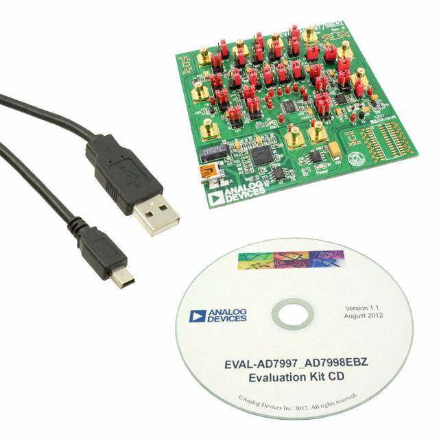
ICGOO电子元器件商城为您提供ADS1148EVM由Texas Instruments设计生产,在icgoo商城现货销售,并且可以通过原厂、代理商等渠道进行代购。 ADS1148EVM价格参考。Texas InstrumentsADS1148EVM封装/规格:评估板 - 模数转换器(ADC), ADS1148 - 16 Bit 5 ~ 2k Samples per Second Analog to Digital Converter (ADC) Evaluation Board。您可以下载ADS1148EVM参考资料、Datasheet数据手册功能说明书,资料中有ADS1148EVM 详细功能的应用电路图电压和使用方法及教程。
Texas Instruments 的 ADS1148EVM 是一款用于评估 24 位 ADC(模数转换器)ADS1148 的评估板。该芯片具有高精度、低功耗特性,主要面向需要精密模拟信号采集的应用场景。

ADS1148EVM 常用于以下应用场景:

1. 工业自动化与过程控制:如温度、压力、流量等传感器信号的高精度采集,适用于PLC(可编程逻辑控制器)和智能变送器设计评估。

2. 测试与测量设备:用于开发高精度万用表、数据采集系统(DAQ)、传感器接口模块等,提供稳定可靠的模数转换性能验证平台。

3. 医疗仪器:如便携式监护设备、诊断仪器中的生物电信号采集,支持对微弱信号的精确处理和分析。

4. 能源监测系统:适用于智能电表、电力质量分析仪等设备中,用于电流、电压等参数的高分辨率采集。

5. 科研与教学实验:作为教学工具或研究平台,帮助工程师和学生理解高精度ADC的工作原理及应用方法。

ADS1148EVM 提供完整的硬件评估环境,便于用户快速评估芯片性能,缩短产品开发周期。
| 参数 | 数值 |
| ADC数 | 1 |
| 产品目录 | 编程器,开发系统嵌入式解决方案 |
| 描述 | EVAL MODULE FOR ADS1148数据转换 IC 开发工具 ADS1148 Eval Mod |
| 产品分类 | 评估板 - 模数转换器 (ADC)工程工具 |
| 品牌 | Texas Instruments |
| 产品手册 | http://www.ti.com/lit/pdf/sbau142 |
| 产品图片 |
|
| rohs | 否含铅 / 不符合限制有害物质指令(RoHS)规范要求 |
| 产品系列 | 模拟与数字IC开发工具,数据转换 IC 开发工具,Texas Instruments ADS1148EVM- |
| 数据手册 | http://www.ti.com/lit/pdf/sbau142点击此处下载产品Datasheet |
| 产品型号 | ADS1148EVM |
| 不同条件下的功率(典型值) | 2.3mW @ 20sps |
| 产品 | Evaluation Boards |
| 产品种类 | 数据转换 IC 开发工具 |
| 位数 | 16 |
| 使用的IC/零件 | ADS1148 |
| 其它名称 | 296-27324 |
| 制造商产品页 | http://www.ti.com/general/docs/suppproductinfo.tsp?distId=10&orderablePartNumber=ADS1148EVM |
| 商标 | Texas Instruments |
| 工作温度 | -40°C ~ 125°C |
| 工作电源电压 | 5.5 V |
| 工具用于评估 | ADS1148 |
| 工厂包装数量 | 1 |
| 所含物品 | 板 |
| 接口类型 | USB |
| 数据接口 | SPI |
| 标准包装 | 1 |
| 类型 | ADC |
| 输入范围 | ±VREF/增益 |
| 采样率(每秒) | 5 ~ 2k |


- 商务部:美国ITC正式对集成电路等产品启动337调查
- 曝三星4nm工艺存在良率问题 高通将骁龙8 Gen1或转产台积电
- 太阳诱电将投资9.5亿元在常州建新厂生产MLCC 预计2023年完工
- 英特尔发布欧洲新工厂建设计划 深化IDM 2.0 战略
- 台积电先进制程称霸业界 有大客户加持明年业绩稳了
- 达到5530亿美元!SIA预计今年全球半导体销售额将创下新高
- 英特尔拟将自动驾驶子公司Mobileye上市 估值或超500亿美元
- 三星加码芯片和SET,合并消费电子和移动部门,撤换高东真等 CEO
- 三星电子宣布重大人事变动 还合并消费电子和移动部门
- 海关总署:前11个月进口集成电路产品价值2.52万亿元 增长14.8%
PDF Datasheet 数据手册内容提取
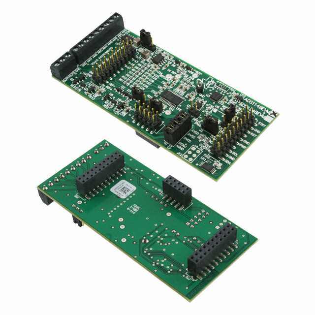
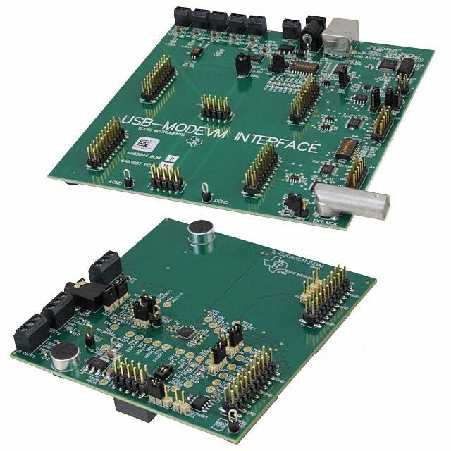
User's Guide SBAU142B–April2009–RevisedMay2011 ADS1148EVM, ADS1248EVM, ADS1148EVM-PDK, and ADS1248EVM-PDK ADS1248EVM(Left)andADS1248EVM-PDK(Right) This user's guide describes the characteristics, operation, and use of the ADS1148EVM and ADS1248EVM, both by themselves and as part of the ADS1148EVM-PDK or ADS1248EVM-PDK. These evaluation modules (EVMs) are evaluation boards for the ADS1248, a 24-bit, multi-channel, delta-sigma analog-to-digital converter (ADC), and the ADS1148, a 16-bit version of the ADS1248. This EVM allows evaluation of all aspects of the ADS1148 or ADS1248 devices. Complete circuit descriptions, schematic diagrams,andbillsofmaterialareincludedinthisdocument. The following related documents are available for download through the Texas Instruments web site at http://www.ti.com. EVM-CompatibleDeviceDataSheets Device LiteratureNumber ADS1148 SBAS453 ADS1248 SBAS426A REF5020 SBOS410D OPA227 SBOS110A TPS3836L30 SLVS292D TPS79225 SLVS337B TPS72325 SLVS346B SN74LVC2G157 SCES207K PCA9535 SCPS129I ADCProisatrademarkofTexasInstruments. Microsoft,WindowsareregisteredtrademarksofMicrosoftCorporation. I2CisatrademarkofNXPSemiconductors. Allothertrademarksarethepropertyoftheirrespectiveowners. SBAU142B–April2009–RevisedMay2011 ADS1148EVM,ADS1248EVM,ADS1148EVM-PDK,andADS1248EVM-PDK 1 SubmitDocumentationFeedback Copyright©2009–2011,TexasInstrumentsIncorporated
www.ti.com Contents 1 EVMOverview............................................................................................................... 3 2 AnalogInterface ............................................................................................................. 3 3 DigitalInterface .............................................................................................................. 4 4 PowerSupplies .............................................................................................................. 5 5 VoltageReference .......................................................................................................... 6 6 ClockSource ................................................................................................................ 6 7 EVMOperation .............................................................................................................. 7 8 ADS1248EVM-PDKKitOperation ........................................................................................ 8 9 EvaluatingPerformancewiththeADCProSoftware .................................................................. 17 10 SchematicsandLayout ................................................................................................... 29 ListofFigures 1 ReferenceSelectSwitchS1............................................................................................... 6 2 JumperJ2.................................................................................................................... 7 3 ADS1248EVMDefaultJumperLocations................................................................................ 8 4 VirtualCOMPortInstaller.................................................................................................. 9 5 VirtualCOMPortSetup.................................................................................................... 9 6 MMB3SwitchLocations.................................................................................................. 10 7 ConnectingADS1248EVMtoMMB3 ................................................................................... 11 8 MMB3BlockDiagram..................................................................................................... 12 9 ADCProSoftwareStart-upDisplayWindow........................................................................... 13 10 ADS1248EVM-PDKPlug-InDisplayWindow.......................................................................... 14 11 ConnectionTimeout....................................................................................................... 15 12 FirmwareDownloadMessageBox...................................................................................... 15 13 FirmwareDownloadProgressIndicator................................................................................ 16 14 FirmwareDownloadCompleteMessageBox......................................................................... 17 15 ADS1248Multiplexer...................................................................................................... 18 16 I/OConfigTab............................................................................................................. 19 17 EnablingVBIASonaChannel........................................................................................... 20 18 GPIOTab................................................................................................................... 21 19 GPIOSettoOutputMode................................................................................................ 22 20 GPIOOutputSettoHigh................................................................................................. 23 21 Power&RefTab.......................................................................................................... 24 22 CalTab ..................................................................................................................... 26 23 AboutTab .................................................................................................................. 27 24 ProgressBarWhileCollectingData .................................................................................... 28 ListofTables 1 J8/J4:AnalogInterfacePinout............................................................................................ 4 2 J7:SerialInterfacePins.................................................................................................... 4 3 J11Configuration:Power-SupplyInput.................................................................................. 5 4 J10Configuration:PowerOptions........................................................................................ 5 5 REF1ReferenceVoltageOptions........................................................................................ 6 6 ListofSwitches.............................................................................................................. 8 7 ADS1148EVM/ADS1248EVMBillofMaterials ....................................................................... 29 2 ADS1148EVM,ADS1248EVM,ADS1148EVM-PDK,andADS1248EVM-PDK SBAU142B–April2009–RevisedMay2011 SubmitDocumentationFeedback Copyright©2009–2011,TexasInstrumentsIncorporated
www.ti.com EVMOverview 1 EVM Overview 1.1 Features ADS1148EVM/ADS1248EVMFeatures: • ContainsallsupportcircuitryneededfortheADS1148/ADS1248 • ±2.5Vand+5Vpower-supplyoptionsforADC • Voltagereferenceoptions:externaloronboard • GPIOaccess • CompatiblewiththeTIModularEVMSystem ADS1148EVM-PDK/ADS1248EVM-PDKFeatures: • Easy-to-useevaluationsoftwareforMicrosoft®Windows® XP • Datacollectiontotextfiles • Built-inanalysistoolsincludingscope,FFT,andhistogramdisplays • Completecontrolofboardsettings • Easilyexpandablewithnewanalysisplug-intoolsfromTexasInstruments Forusewithacomputer,theADS1148EVM-PDKorADS1248EVM-PDKisavailable.Thiskitcombines theADS1148/ADS1248EVMboardwiththeMSP430-basedMMB3motherboard,andincludesADCPro™ softwareforevaluation. TheMMB3motherboardallowstheADS1148/ADS1248EVMtobeconnectedtothecomputerviaan availableUSBport.ThismanualshowshowtousetheMMB3aspartofthe ADS1148EVM-PDK/ADS1248EVM-PDK,butdoesnotprovidetechnicaldetailsabouttheMMB3itself. ADCProisaprogramforcollecting,recording,andanalyzingdatafromADCevaluationboards.Itisbased onanumberofplug-inprograms,soitcanbeexpandedeasilywithnewtestanddatacollectionplug-ins. TheADS1148EVM-PDK/ADS1248EVM-PDKiscontrolledbyaplug-inthatrunsinADCPro.Formore informationaboutADCPro,seetheADCPro™Analog-to-DigitalConverterEvaluationSoftwareUser's Guide(literaturenumberSBAU128),availablefordownloadfromtheTIwebsite. ThismanualcoverstheoperationofboththeADS1148/ADS1248EVMandthe ADS1148EVM-PDK/ADS1248EVM-PDK.Throughoutthisdocument,theabbreviationEVMandtheterm evaluationmodulearesynonymouswiththeADS1148/ADS1248EVM.Forclarityofreading,theremainder ofthismanualwillreferonlytotheADS1248EVMorADS1248EVM-PDK,butoperationoftheEVMandkit fortheADS1148isidentical,unlessotherwisenoted. 1.2 Introduction TheADS1248EVMisanevaluationmodulebuilttotheTIModularEVMSystemspecification.Itcanbe connectedtoanymodularEVMsysteminterfacecard. TheADS1248EVMisavailableasastand-aloneprintedcircuitboard(PCB)oraspartofthe ADS1248EVM-PDK,whichincludesanMMB3motherboardandsoftware.Asastand-alonePCB,the ADS1248EVMisusefulforprototypingdesignsandfirmware. NotethattheADS1248EVMhasnomicroprocessorandcannotrunsoftware.Toconnectittoacomputer, sometypeofinterfaceisrequired. 2 Analog Interface Formaximumflexibility,theADS1248EVMisdesignedforeasyinterfacingtomultipleanalogsources. SamtecpartnumbersSSW-110-22-F-D-VS-KandTSM-110-01-T-DV-Pprovideaconvenient10-pin, dual-row,header/socketcombinationatJ8.Thisheader/socketprovidesaccesstotheanaloginputpinsof theADS1248.ConsultSamtecathttp://www.samtec.comorcall1-800-SAMTEC-9foravarietyofmating connectoroptions.ThesesignalscanalsobeconnectedtotheterminalblockJ4. SBAU142B–April2009–RevisedMay2011 ADS1148EVM,ADS1248EVM,ADS1148EVM-PDK,andADS1248EVM-PDK 3 SubmitDocumentationFeedback Copyright©2009–2011,TexasInstrumentsIncorporated
DigitalInterface www.ti.com AllofthepinsonJ4andJ8areconnectedwithminimalfilteringorprotection.Useappropriatecaution whenhandlingthesepins.Table1summarizesthepinoutsforanaloginterfacesJ4andJ8. Table1.J8/J4:AnalogInterfacePinout PinNumber Signal Description,ADS1148/ADS1248 J8.1,J4-1 A0(–) AIN0 J8.2,J4-2 A0(+) AIN1 J8.3,J4-3 A1(–) AIN2 J8.4,J4-4 A1(+) AIN3 J8.5,J4-5 A2(–) AIN4 J8.6,J4-6 A2(+) AIN5 J8.7,J4-7 A3(–) AIN6 J8.8,J4-8 A3(+) AIN7 J8.18 REF– Externalreferencesourceinput(– sideofdifferentialinput) J8.20 REF+ Externalreferencesourceinput(+ sideofdifferentialinput) J8.10-16(even) Unused J8.15 Unused J8.9-19(odd),J4-9 AGND Analoggroundconnections (exceptJ8.15) 3 Digital Interface 3.1 Serial Data Interface TheADS1248EVMisdesignedtoeasilyinterfacewithmultiplecontrolplatforms.Samtecpartnumbers SSW-110-22-F-D-VS-KandTSM-110-01-T-DV-Pprovideaconvenient10-pin,dual-row,header/socket combinationatJ7.Thisheader/socketprovidesaccesstothedigitalcontrolandserialdatapinsofthe ADC.ConsultSamtecathttp://www.samtec.comorcall1-800-SAMTEC-9foravarietyofmating connectoroptions. AlllogiclevelsonJ7are3.3VCMOS,exceptfortheI2C™pins.Thesepinsconformto3.3VI2Crules. Table2describestheJ7serialinterfacepins. Table2.J7:SerialInterfacePins PinNo. PinName SignalName I/OType Pullup Function J7.1 CNTL CS In High J7.2 GPIO0 START In High J7.3 CLKX SCLK In None ADS1248SPIclock J7.4 DGND DGND In/Out None Digitalground J7.5 CLKR Unused – – J7.6 GPIO1 MR In High Masterreset J7.7 FSX Unused – – J7.8 GPIO2 Unused – – J7.9 FSR DRDY Out None J7.10 DGND DGND In/Out None Digitalground J7.11 DX DIN In None ADS1248SPIdatain J7.12 GPIO3 PWRSEL In High Selects±2.5Vor+5V supply J7.13 DR DOUT/DRDY Out None ADS1248dataout J7.14 GPIO4 Unused – – J7.15 INT DRDY Out None 4 ADS1148EVM,ADS1248EVM,ADS1148EVM-PDK,andADS1248EVM-PDK SBAU142B–April2009–RevisedMay2011 SubmitDocumentationFeedback Copyright©2009–2011,TexasInstrumentsIncorporated
www.ti.com PowerSupplies Table2.J7:SerialInterfacePins (continued) PinNo. PinName SignalName I/OType Pullup Function J7.16 SCL SCL I2C High I2Cclock J7.17 TOUT CLK In None Canbeusedtoprovide aclockfroma processor J7.18 DGND DGND In/Out None Digitalground J7.19 GPIO5 CLKSelect – None J7.20 SDA SDA I2C High I2Cdata ManypinsonJ7haveweakpull-upresistors.Theseresistorsprovidedefaultsettingsformanyofthe controlpins.ManypinsonJ7corresponddirectlytoADS1248pins.SeetheADS1248productdatasheet forcompletedetailsonthesepins. 4 Power Supplies J11isthepower-supplyinputconnector.Table3liststheconfigurationdetailsforJ11. Table3.J11Configuration:Power-SupplyInput PinNo. PinName Function Required J11.1 +VA Unused No J11.2 –VA Unused No J11.3 +5VA +5Vanalogsupply Always J11.4 –5VA –5Vanalogsupply Onlyinbipolarmode J11.5 DGND Digitalgroundinput Yes J11.6 AGND Analoggroundinput Yes J11.7 +1.8VD 1.8Vdigitalsupply No J11.8 VD1 Unused No J11.9 +3.3VD 3.3Vdigitalsupply Always J11.10 +5VD +5Vdigitalsupply No Allofthepowersupplies(AVDD,AVSS,andDVDD)havecorrespondingjumpersonJ10thatcanbe replacedwithacurrentmetertomeasuretherespectivesupplycurrents. 4.1 Power Options J10isarrangedasfiverows,eachofwhichcanbeshorted.Table4liststhepoweroptiondetailsforJ10. Fornormaloperation,J10.1-2,J10.3-4,andJ10.5-6mustbeconnected(directorthroughanammeter), andeither(orboth)ofJ10.7-8andJ10.9-10mustbeconnected;otherwise,theboarddoesnotfunction. Table4.J10Configuration:PowerOptions Row Name Function 1-2 ADCAVDD AVDDsupplycurrentmeasurementpointfortheADC.Mustbe connectedforoperation. 3-4 ADCAVSS AVSSsupplycurrentmeasurementpointfortheADC.Mustbe connectedforoperation. 5-6 ADCDVDD DVDDsupplycurrentmeasurementpointfortheADC.Mustbe connectedforoperation. 7-8 DGND ConnectsDGNDtoboardground. 9-10 AGND ConnectsAGNDtoboardground. SBAU142B–April2009–RevisedMay2011 ADS1148EVM,ADS1248EVM,ADS1148EVM-PDK,andADS1248EVM-PDK 5 SubmitDocumentationFeedback Copyright©2009–2011,TexasInstrumentsIncorporated
VoltageReference www.ti.com 5 Voltage Reference TheADS1248devicehastheoptionofselectingbetweenthreedifferentreferences:REF0,REF1,andthe internalreference,throughregistersintheADS1248chip.TheEVMprovidesa2.048Vreferencefor REF1fromU1,filteredandbufferedthroughU2.This2.048VmaybeusedtodrivetheREF1Pinput. REF1PshouldnotbeconnectedtoAVDDthroughswitchS1becausethisconnectionwillviolatethe specificationforthemaximumreferenceinput.Figure1showsswitchS1asitappearsontheEVM.The lowsideofthereference(REF1N)istiedtoAVSS.Thedifferentreferenceoptionsunderdifferentsupply conditionsareoutlinedinTable5. Figure1.ReferenceSelectSwitchS1 Table5.REF1ReferenceVoltageOptions REF1 S1Position Reference AVDD AVSS J1Setting (1) REF1P REF1N Voltage 5V 0V 1-2 BUFF 2.048V 0V 2.048V 5V 0V 2-3 BUFF 0V 0V Invalid selection 2.5V –2.5V 1-2 BUFF –0.452V –2.5V 2.048V 2.5V –2.5V 2-3 BUFF 0V –2.5V 2.5V (1) SwitchS1shouldnotbesettoAVDD. TheREF0NandREF0PpinsareconnecteddirectlytotheexternalreferencepinsonJ8.18andJ8.20, respectively.Thesepinsarediode-clampedtoAVDDandAVSS,andprotectedwithD3,a5.1Vzener.If theexternalreferencepinsarenotsuppliedwithaexternalsource,REF0NwillbeatapproximatelyAVSS +0.6V,andREF0PwillbeatapproximatelyAVDD–0.6V. TheinternalreferencevoltagecanbemeasuredbetweentestpointsTP3(IntREF)andTP5(REFCOM). 6 Clock Source TheADS1248hasaninternalclockorcanbeprovidedanexternalclock.TheEVMusestheinternalclock modeonly.ProvisionismadeontheEVMcircuitboard,however,foranexternalclocksource.Afootprint isprovidedatU8foracrystaloscillatortobemountedontheboard.Anexternalclockmayalsobe providedbyaprocessorontheTOUTpin(J7.17),oranexternalclocksourceconnectedtoJ14.1(ground) andJ14.2(signal). J2controlshowtheclocksourceisselected.WithpinsJ2.1andJ2.2shorted,GPIO5fromJ7.19can controlwhethertheAorBsideofU7isselected.IftheAsideisselected,theclockshouldcomefroman externalsourceprovidedasdescribedabove.IftheBsideisselected,theclockshouldcomefromthe crystaloscillator.Ifaselectionismadeandnoclockisprovidedonthatinput,theADS1248detectsthat noexternalclockispresentandenablesitsinternaloscillator. 6.1 Usage in PDK IfusingtheADS1248EVMaspartoftheADS1248EVM-PDK,J14shouldhaveajumperinstalled. RemoveanyshortingblocksonjumperJ13,andmakesureJ2hasajumperbetweenpins1and2(theIO position).ThisconfigurationgroundstheCLKinputtotheADS1248andensuresthattheinternaloscillator startsup. 6 ADS1148EVM,ADS1248EVM,ADS1148EVM-PDK,andADS1248EVM-PDK SBAU142B–April2009–RevisedMay2011 SubmitDocumentationFeedback Copyright©2009–2011,TexasInstrumentsIncorporated
www.ti.com EVMOperation 6.2 Usage as a Stand-Alone EVM IfusingtheEVMinyourownsystemandnotwiththePDKhardwareandsoftware,observethefollowing recommendations: • J13shouldberemovediftheexternalclocksourceisusedandtheTOUTpinisstilldrivenbya processorinordertoavoidconflicts. • JumperJ2canbeusedtoalwaysselecttheU8oscillator(DVDDposition)orallowthe onboard/externalclockselectiontobecontrolledbyGPIO5(J7.19)asshowninFigure2. Figure2.JumperJ2 7 EVM Operation Thissectionprovidesinformationontheanaloginput,digitalcontrol,andgeneraloperatingconditionsof theADS1248EVM. 7.1 Analog Input EachoftheanaloginputsourcescanbeapplieddirectlytoJ8(toporbottomside)orthrough signal-conditioningmodulesavailableforthethemodularEVMsystem.TerminalblockJ4isconnectedin parallelwiththeanalogsignalconnectionstoJ8.Eachinputhasa47Ω/47pFRCfilterinserieswithit,and adifferential0.1μFcapacitorisplacedacrosseachinputpairforusewithdifferentialsignals. 7.2 Digital Control ThedigitalcontrolsignalscanbeapplieddirectlytoJ7(toporbottomside).ThemodularADS1248EVM canalsobeconnecteddirectlytoaDSPormicrocontrollerinterfaceboard,suchasthe5-6KInterfaceor HPA-MCUInterfaceboardsavailablefromTexasInstruments,ortheMMB3ifpurchasedaspartofthe ADS1248EVM-PDK.Foralistofcompatibleinterfaceand/oraccessoryboardsfortheEVMorthe ADS1248,seetherelevantproductfolderontheTIwebsite. SBAU142B–April2009–RevisedMay2011 ADS1148EVM,ADS1248EVM,ADS1148EVM-PDK,andADS1248EVM-PDK 7 SubmitDocumentationFeedback Copyright©2009–2011,TexasInstrumentsIncorporated
ADS1248EVM-PDKKitOperation www.ti.com 7.3 Default Jumper Settings and Switch Positions Figure3showsthejumpersfoundontheEVMandtherespectivefactorydefaultconditionsforeach. Figure3.ADS1248EVMDefaultJumperLocations Table6liststheswitchesfoundontheEVMandtherespectivefactorydefaultconditionsforeach. Table6.ListofSwitches Switch DefaultPosition SwitchDescription S1 Left Onboardreference 8 ADS1248EVM-PDK Kit Operation ThissectionprovidesinformationonusingtheADS1248EVM-PDK,includingsetup,programinstallation, andprogramusage. TopreparetoevaluatetheADS1248withtheADS1248EVM-PDK,completethefollowingsteps: Step1. InstalltheADCProsoftware(ifnotalreadyinstalled)onaPC. Step2. InstalltheADS1248EVM-PDKEVMplug-insoftware. Step3. CompletetheUSBdriverinstallationprocess. Step4. SetuptheADS1248EVM-PDK. Step5. ConnecttheADS1248EVM-PDKtothecomputerwithaUSBcable. Step6. RuntheADCProsoftware. Eachtaskisdescribedinthesubsequentsectionsofthisdocument. 8 ADS1148EVM,ADS1248EVM,ADS1148EVM-PDK,andADS1248EVM-PDK SBAU142B–April2009–RevisedMay2011 SubmitDocumentationFeedback Copyright©2009–2011,TexasInstrumentsIncorporated
www.ti.com ADS1248EVM-PDKKitOperation 8.1 Installing the ADCPro Software CAUTION Do not connect the ADS1248EVM-PDK before installing the software on a suitable PC. Failure to observe this caution may cause Microsoft Windows to notrecognizetheADS1248EVM-PDKasaconnecteddevice. TheCD-ROMshippedwiththeADS1248EVMcontainsaninstallerforADCProaswellasaninstallerfor theADS1248EVMplug-in.ThelatestsoftwareisavailablefromtheTIwebsiteathttp://www.ti.com/.Refer totheADCProUserGuideforinstructionsoninstallingandusingADCPro. ToinstalltheADS1248EVM-PDKplug-in,runthefile:ads1248evm-pdk-plug-in-1.0.0.exe(1.0.0isthe versionnumber,andincrementswithsoftwareversionreleases;youmayhaveadifferentversiononyour CD).Double-clickthefiletorunit;thenfollowtheinstructionsshown.YoucanalsoutilizetheADCPro UpdateCheckfeaturetocheckfornewerversionsoftheADS1248EVM-PDKplug-in,onceyouhave installedaversionofit. Followtheon-screenprompts.OncetheADCProplug-ininstalls,youwillbepromptedtoinstalltheVirtual COMportdriverasshowninFigure4. Figure4.VirtualCOMPortInstaller PressOK,andthescreenshowninFigure5isdisplayed. Figure5.VirtualCOMPortSetup IfyoualreadyhaveaTUSB3410VirtualCOMportdriverinstalledonyoursystem,selectCancel; otherwise,pressSetupandfollowtheon-screenprompts.Youmaybenotifiedthatthedriverisnot digitallysigned.Ifthismessageappears,selectContinueAnywayandproceed. SBAU142B–April2009–RevisedMay2011 ADS1148EVM,ADS1248EVM,ADS1148EVM-PDK,andADS1248EVM-PDK 9 SubmitDocumentationFeedback Copyright©2009–2011,TexasInstrumentsIncorporated
ADS1248EVM-PDKKitOperation www.ti.com 8.2 Setting Up the ADS1248EVM-PDK TheADS1248EVM-PDKcontainsboththeADS1248EVMandtheMMB3motherboard;however,the devicesareshippedunconnected.FollowthesestepstosetuptheADS1248EVM-PDK. Step1. UnpacktheADS1248EVM-PDKkit. Step2. SettheswitchesontheMMB3asdescribedbelow,asshowninFigure6. • SetswitchSW4totheright. • SettheDACswitch(SW5)totheOUTposition(totheright). Figure6.MMB3SwitchLocations Step3. PlugtheADS1248EVMintotheMMB3asFigure7illustrates. 10 ADS1148EVM,ADS1248EVM,ADS1148EVM-PDK,andADS1248EVM-PDK SBAU142B–April2009–RevisedMay2011 SubmitDocumentationFeedback Copyright©2009–2011,TexasInstrumentsIncorporated
www.ti.com ADS1248EVM-PDKKitOperation Figure7.ConnectingADS1248EVMtoMMB3 CAUTION Do not misalign the pins when plugging the ADS1248EVM into the MMB3. CheckthepinalignmentcarefullybeforeapplyingpowertothePDK. Step4. SetthejumpersandswitchesontheADS1248EVMasshowninFigure3(notethatthese settingsarethefactory-configuredsettingsfortheEVM). 8.2.1 AbouttheMMB3 TheMMB3isaModularEVMSystemmotherboard.ItisdesignedaroundtheMSP430F449,alow-power microcontrollerfromTexasInstruments.Figure8showsablockdiagramoftheMMB3. SBAU142B–April2009–RevisedMay2011 ADS1148EVM,ADS1248EVM,ADS1148EVM-PDK,andADS1248EVM-PDK 11 SubmitDocumentationFeedback Copyright©2009–2011,TexasInstrumentsIncorporated
ADS1248EVM-PDKKitOperation www.ti.com USB USB RESET +5VA -5VA +5VD +3.3V PWR & VREF +1.8V +10V -10V TUSB3410 Supplied to LCD DISPLAY Daughtercard Power Connector 2.5V OPER BSL +1 DAC1220 MSP430F449 RESET -1 DAC IN OUT Daughtercard Analog Modular Serial Connectors Power Joystick Power from PWR & VREF Block Figure8.MMB3BlockDiagram TheMMB3wasdesignedtobeusedasastand-alonedemonstrationplatformforlow-speeddata converters.Itfeaturesanonboard,20-bitdigital-to-analogconverter(DAC)thatcanbeusedasasignal sourceforanADCundertest,andhasajoystickforcontroloffunctionsontheboardwhenitisnot controlledbyaPC.ThesefeaturesareexperimentalandnotsupportedintheADS1248EVM-PDKat thistime. TheMMB3derivespowerfromtheUSBinterface,andgenerates+5VD,3.3V,and1.8V,aswellas+5VA and–5VAand ±10V.The±10Vissuppliedtothedaughtercardpowerconnectoras+VAand–VA. TheMMB3isnotsoldasamicrocontrollerdevelopmentboard,anditisnotavailableseparately.TIcannot offersupportfortheMMB3exceptaspartofanEVMkit.Forschematicsorotherinformationaboutthe MMB3,contactTexasInstruments. 8.3 EVM Power Supply TheADS1248EVM-PDKispoweredcompletelyfromtheUSBconnectionontheMMB3.TheMMB3 provides3.3Vand±5VtotheADS1248EVM. 8.4 Running the Software and Download of Firmware to MMB3 NOTE: Thesoftwareiscontinuallyunderdevelopment.Theseinstructionsandscreenimagesare currentatthetimeofthiswriting,butmaynotexactlymatchfuturereleases. TheprogramforevaluatingtheADS1248EVM-PDKiscalledADCPro.Thisprogramusesplug-insto communicatewiththeEVM.TheADS1248EVM-PDKplug-inisincludedintheADS1248EVM-PDK package. 12 ADS1148EVM,ADS1248EVM,ADS1148EVM-PDK,andADS1248EVM-PDK SBAU142B–April2009–RevisedMay2011 SubmitDocumentationFeedback Copyright©2009–2011,TexasInstrumentsIncorporated
www.ti.com ADS1248EVM-PDKKitOperation TheprogramcurrentlyrunsonlyonMicrosoftWindowsplatformsofWindowsXP;WindowsVistaisNOT supported. IfthisisthefirsttimeinstallingADCProandplug-ins,followtheseprocedurestorunADCProandperform anynecessaryfirmwareinstallations.MakesuretheADCProsoftwareanddeviceplug-insoftwareare installedfromtheCD-ROMasdescribedinSection8.1,InstallingtheADCProSoftware. Step1. StartthesoftwarebyselectingADCProfromtheWindowsStartmenu.ThescreeninFigure9 appears. Figure9.ADCProSoftwareStart-upDisplayWindow SBAU142B–April2009–RevisedMay2011 ADS1148EVM,ADS1248EVM,ADS1148EVM-PDK,andADS1248EVM-PDK 13 SubmitDocumentationFeedback Copyright©2009–2011,TexasInstrumentsIncorporated
ADS1248EVM-PDKKitOperation www.ti.com break Step2. SelectADS1248EVMfromtheEVMdrop-downmenu.TheADS1248EVM-PDKplug-in appearsintheleftpane,asshowninFigure10. Figure10.ADS1248EVM-PDKPlug-InDisplayWindow Step3. TheADS1248EVM-PDKplug-inwindowhasastatusareaatthetopofthescreen.Whenthe plug-inisfirstloaded,theplug-insearchesfortheboard.Youwillseeaseriesofmessages inthestatusareaindicatingthisaction. 14 ADS1148EVM,ADS1248EVM,ADS1148EVM-PDK,andADS1248EVM-PDK SBAU142B–April2009–RevisedMay2011 SubmitDocumentationFeedback Copyright©2009–2011,TexasInstrumentsIncorporated
www.ti.com ADS1248EVM-PDKKitOperation break Step4. Iftheplug-incannotconnecttotheEVM,youwillseeawindowasshowninFigure11.This messagemayindicatethatthefirmwareisnotloadedontheMMB3.YoumayselectRetry AutoConnect;ifthatactionfails,selectRetryManualConnectandspecifytheCOMportto beused. Figure11.ConnectionTimeout Step5. Theplug-indetectswhetherornottheboardhasthecorrectfirmwareloaded.Thefirsttime youusetheADS1248EVM-PDK,thefirmwarefortheMMB3mayneedtobedownloadedto theMMB3.Ifthefirmwareneedstobeloaded,youwillseeascreenasshowninFigure12. Figure12.FirmwareDownloadMessageBox SBAU142B–April2009–RevisedMay2011 ADS1148EVM,ADS1248EVM,ADS1148EVM-PDK,andADS1248EVM-PDK 15 SubmitDocumentationFeedback Copyright©2009–2011,TexasInstrumentsIncorporated
ADS1248EVM-PDKKitOperation www.ti.com SwitchtheBSLswitch(SW4)ontheMMB3totheBSLposition(totheleft)asinstructed,thenpress OK.Theplug-inwilldownloadthefirmwaretotheMMB3.Thisoperationmaytakeacoupleofminutes, sotheprogressisupdatedinthemessageatthetopoftheADS1248plug-inwindow(asFigure13 shows).ThefirmwareissavedinflashmemoryontheMMB3,sothisoperationshouldonlyneedtobe performedonce. Figure13.FirmwareDownloadProgressIndicator 16 ADS1148EVM,ADS1248EVM,ADS1148EVM-PDK,andADS1248EVM-PDK SBAU142B–April2009–RevisedMay2011 SubmitDocumentationFeedback Copyright©2009–2011,TexasInstrumentsIncorporated
www.ti.com EvaluatingPerformancewiththeADCProSoftware Whenthefirmwaredownloadcompletes,themessageboxshowninFigure14appears.Followthe on-screeninstructionsandtheplug-inshouldnowconnecttotheEVM. Figure14.FirmwareDownloadCompleteMessageBox 9 Evaluating Performance with the ADCPro Software TheevaluationsoftwareisbasedonADCPro,aprogramthatoperatesusingavarietyofplug-ins.Touse ADCPro,loadanEVMplug-inandatestplug-in.ToloadanEVMplug-in,selectitfromtheEVMmenu. Toloadatestplug-in,selectitfromtheTestmenu.Tounloadaplug-in,selecttheUnloadoptionfromthe correspondingmenu. Onlyoneofeachkindofplug-incanbeloadedatatime.Ifyouselectadifferentplug-in,theprevious plug-inisunloaded. 9.1 Using the ADS1248EVM-PDK Plug-in TheADS1248EVM-PDKplug-inforADCProprovidescompletecontroloverallsettingsoftheADS1248.It consistsofatabbedinterface(seeFigure16),withdifferentfunctionsavailableondifferenttabs.These controlsaredescribedinthissection. YoucanadjusttheADS1248EVMsettingswhenyouarenotacquiringdata.Duringacquisition,all controlsaredisabledandsettingsmaynotbechanged. WhenyouchangeasettingontheADS1248EVMplug-in,thesettingimmediatelyupdatesontheboard. SettingsontheADS1248EVMcorrespondtosettingsdescribedintheADS1248datasheet(availablefor downloadatwww.ti.com)fordetails. TheADS1248EVM-PDKplug-inhasatabbedinterface,withfivedifferenttabstocontrolthefunctionsof theADS1248.Thesetabsaredescribedbelow. SBAU142B–April2009–RevisedMay2011 ADS1148EVM,ADS1248EVM,ADS1148EVM-PDK,andADS1248EVM-PDK 17 SubmitDocumentationFeedback Copyright©2009–2011,TexasInstrumentsIncorporated
EvaluatingPerformancewiththeADCProSoftware www.ti.com 9.1.1 I/OConfigTab ThistabistheprimarytabthatcontrolsthefunctionofthemultiplexerintheADS1248.Recallthatthe ADS1248multiplexerisconfiguredasshowninFigure15.Bydefault,allchannelsaresetasanalog inputs;theIDACsarenotroutedtoanychannelandtheIDACcontrolsaredisabled.Thesecontrolsare enabledwhenthecorrectIDACsettingsaremadeonthePower&Reftab(seeSection9.1.3). AVDD AVDD IDAC2 IDAC1 System Monitors AVSS AVDD VBIAS (MUXCAL = 001) AVDD AVDD AIN0 AVSS AVDD VBIAS Temperature VREFP Diode VREFN AIN1 ADS1247/48 Only VREFP1/4 AVSS AVDD VBIAS VREFN1/4 AIN2 VREFP0/4 VREFN0/4 AVSS AVDD VBIAS AVDD/4 AIN3 AVSS/4 DVDD/4 ADS1248 Only DVSS/4 AVSS AVDD VBIAS AIN4 AVDD AVSS AVDD VBIAS Burnout Current Source (0.5mA, 2mA, 10mA) AIN5 AIN P To PGA AVSS AVDD VBIAS AINN ADC AIN6 Burnout Current Source AVSS AVDD VBIAS (0.5mA, 2mA, 10mA) AIN7 AVSS Figure15.ADS1248Multiplexer Theradiobuttonsatthefarrightofthepanel(seeFigure16)selectwhichpairofinputsareconnectedto thePGA.Notethatyoumayselectthesameinputforboththepositive(AINP)andnegative(AINN)input; thisconfigurationisoftenselectedtoperformanoisetestontheADCitself. 18 ADS1148EVM,ADS1248EVM,ADS1148EVM-PDK,andADS1248EVM-PDK SBAU142B–April2009–RevisedMay2011 SubmitDocumentationFeedback Copyright©2009–2011,TexasInstrumentsIncorporated
www.ti.com EvaluatingPerformancewiththeADCProSoftware InputpinsAIN2-AIN7canbeselectedtobeananaloginputorGPIO.IfaninputistobeusedasaGPIO, checktheGPIOboxasshowninFigure16. Figure16.I/OConfigTab WhenaninputisselectedasaGPIO,itslabelturnsgreenandtheIDACcontrolsforthatchannelare disabled. SBAU142B–April2009–RevisedMay2011 ADS1148EVM,ADS1248EVM,ADS1148EVM-PDK,andADS1248EVM-PDK 19 SubmitDocumentationFeedback Copyright©2009–2011,TexasInstrumentsIncorporated
EvaluatingPerformancewiththeADCProSoftware www.ti.com EachinputchannelcanalsohaveaVBIASappliedtoit.CheckingtheVBIASboxonachannelapplies theVBIASvoltage,whichisapproximatelyhalfthevalueofthesupply.Youcantestthisoptionasshown inFigure17,usingonechanneltiedtoavalueclosetoground(makesureyouobservethe common-moderestrictionslistedintheADS1248productdatasheet)asareferenceforthissignal. Figure17.EnablingVBIASonaChannel TheSystemMonitorbuttonallowsyoutoaccesstheinternalsystemmonitorchannelsoftheADS1248. Whenpressed,thisbuttondisablestheotheranaloginputchannelcontrols,andthesystemmonitor channelselectionsareenabled.YoucanselectOffset,Gain,Temperature,VREF1,VREF0,AVDD,or DVDDasthechanneltoconvert.Notethatsomeofthesechannelsarescaledbyafactorwhenread; refertotheADS1248productdatasheettodeterminethesefactors. ThePGAGaincontrolsetsthePGAgain,andtheDataRatecontrolsetsthedatarateforthedevice. Notethatthedataratecangoquitelow;therefore,iftheblocksizeislarge,thetimeittakestocollecta blockofdatacanbequitelong.Itisadvisabletofirsttestcollectionatthehigherdatarates.Onceatestis knowntoworkproperly,droptoalowerdatarateandallowsufficienttimetocollectthedata. TheBCScontrolsetsthecurrentleveloftheburnoutcurrentsources;itmaybesettoOff,orto0.5μA, 2μA,or10μA. ThePowerDowncontrolpowersdowntheADS1248.NotethatnodatacanbecollectedifthePower Downbuttonisactivated. 20 ADS1148EVM,ADS1248EVM,ADS1148EVM-PDK,andADS1248EVM-PDK SBAU142B–April2009–RevisedMay2011 SubmitDocumentationFeedback Copyright©2009–2011,TexasInstrumentsIncorporated
www.ti.com EvaluatingPerformancewiththeADCProSoftware 9.1.2 GPIOTab WhenaninputisselectedtobeaGPIO,itscontrolsareenabledontheGPIOtab,showninFigure18.By default,theGPIOsareenabledasinputs.PressingtheInputbuttonreadsthestateoftheenabledinputs; iftheinputishigh,thecorrespondinglightturnsgreen. Figure18.GPIOTab SBAU142B–April2009–RevisedMay2011 ADS1148EVM,ADS1248EVM,ADS1148EVM-PDK,andADS1248EVM-PDK 21 SubmitDocumentationFeedback Copyright©2009–2011,TexasInstrumentsIncorporated
EvaluatingPerformancewiththeADCProSoftware www.ti.com TomaketheGPIOanoutput,thetoggleswitchcanbeswitchedtooutputmode,asshowninFigure19. Figure19.GPIOSettoOutputMode 22 ADS1148EVM,ADS1248EVM,ADS1148EVM-PDK,andADS1248EVM-PDK SBAU142B–April2009–RevisedMay2011 SubmitDocumentationFeedback Copyright©2009–2011,TexasInstrumentsIncorporated
www.ti.com EvaluatingPerformancewiththeADCProSoftware WiththeGPIOconfiguredasanoutput,thepushbuttonswitchcontrolsthestateoftheoutputpin.When pressed(asillustratedinFigure20),thebuttonlightsupandtheGPIOissettoahighstate;whenthe switchisdark(asFigure19shows),theGPIOisinalowstate. Figure20.GPIOOutputSettoHigh SBAU142B–April2009–RevisedMay2011 ADS1148EVM,ADS1248EVM,ADS1148EVM-PDK,andADS1248EVM-PDK 23 SubmitDocumentationFeedback Copyright©2009–2011,TexasInstrumentsIncorporated
EvaluatingPerformancewiththeADCProSoftware www.ti.com 9.1.3 Power& RefTab ThePower& ReftabisshowninFigure21.Thistabcontrolstheselectionofthepower-supplymode, referencesources,andIDACs. Figure21.Power& RefTab NotethatwiththeInternalReferenceoff,theIDACcontrolsaredisabled,becausetheIDACscannotbe usedunlesstheinternalreferenceisturnedon. 24 ADS1148EVM,ADS1248EVM,ADS1148EVM-PDK,andADS1248EVM-PDK SBAU142B–April2009–RevisedMay2011 SubmitDocumentationFeedback Copyright©2009–2011,TexasInstrumentsIncorporated
www.ti.com EvaluatingPerformancewiththeADCProSoftware ThePowerSupplycontrolselectsbetweensinglesupply(+5V)modeandbipolarsupply(±2.5V)mode. TheEVMdrawsitssupplyvoltagesfromtheMMB3motherboard,andhasonboardcircuitrytoselect betweenthe+5Vandbipolarsupplies. TheReferenceSelectcontrolselectsbetweenVREF0,VREF1,andtheInternalReference.When VREF1isselected,theVREFvalueissetto2.048V,withswitchS1settoBUFF.S1shouldnotbesetto theAVDDposition,inordertopreventthereferencefromexceedingthemaximumspecifiedinput. Therearetwocheckboxesthat,whenenabled,allowtheREF0PandREF0Npinstobeselectedas GPIOs.ThesecheckboxesareenabledonlyinmodesthatallowthesepinstobeusedasGPIOs. TheInternalReferencecontrolselectswhetherthereferenceisoff,on,orfollowstheSTARTsignal(refer totheADS1248datasheetformoredetailsonthesechoices).Whentheinternalreferenceisenabled,the IDACcontrolsareenabledaswell,becausetheIDACscannotfunctionunlesstheinternalreferenceis turnedon.NotethattheinternalreferencedoesnotnecessarilyhavetobeusedastheADCreferencein ordertousetheIDACs,butitdoesneedtobeturnedon. TheIDACMagnitudecontrolsetstheamountofcurrenteachofthetwoIDACsprovide. TheIDAC0andIDAC1RoutingcontrolsallowyoutospecifywheretheIDAC0orIDAC1currentgo:to eithertheIEXC1orIEXC2pins,ortotheAnaloginputs,oryoumayturntheIDACoff.IftheAINbuttonis selected,thisoptionenablesthecorrespondingIDACcontrolsontheI/OConfigtab. SBAU142B–April2009–RevisedMay2011 ADS1148EVM,ADS1248EVM,ADS1148EVM-PDK,andADS1248EVM-PDK 25 SubmitDocumentationFeedback Copyright©2009–2011,TexasInstrumentsIncorporated
EvaluatingPerformancewiththeADCProSoftware www.ti.com 9.1.4 CalTab TheCaltab(Figure22)controlsthecalibrationfunctionsoftheADS1248. Figure22.CalTab PressingtheSelfOffsetCalibratebuttoncausestheADS1248toperformaselfcalibration;theoffset andfull-scaleregistervaluesarethenupdatedontheplug-inscreen.Youmayalsowritetothese registersbytypinginhexvaluesintheNewfields,thenpresstheSetbutton.Youmayreadthevaluesat anytimebypressingtheReadbutton. 26 ADS1148EVM,ADS1248EVM,ADS1148EVM-PDK,andADS1248EVM-PDK SBAU142B–April2009–RevisedMay2011 SubmitDocumentationFeedback Copyright©2009–2011,TexasInstrumentsIncorporated
www.ti.com EvaluatingPerformancewiththeADCProSoftware 9.1.5 AboutTab TheAbouttabdisplaysinformationabouttheEVMandsoftware,asshowninFigure23. Figure23.AboutTab ThePluginVersionandFirmwareVersionindicatorsshowtheversionnumbersoftheplug-inand firmwarecode,respectively. TheIDindicatorshowsthevalueoftheID[3:0]bitsintheADS1248IDregister. TheNotesindicatormayshowrelevantnotesabouttheplug-inorfirmwarecode,ifthereareany. SBAU142B–April2009–RevisedMay2011 ADS1148EVM,ADS1248EVM,ADS1148EVM-PDK,andADS1248EVM-PDK 27 SubmitDocumentationFeedback Copyright©2009–2011,TexasInstrumentsIncorporated
EvaluatingPerformancewiththeADCProSoftware www.ti.com 9.1.6 CollectingData OnceyouhaveconfiguredtheADS1248foryourtestscenario,presstheADCProAcquirebuttontostart thecollectionofthenumberofdatapointsspecifiedintheTestplug-inBlockSizecontrol.The ADS1248EVM-PDKplug-indisablesallthefrontpanelcontrolswhileacquiring,anddisplaysaprogress barasshowninFigure24. Figure24.ProgressBarWhileCollectingData Formoreinformationontestinganalog-to-digitalconvertersingeneralandusingADCProandtest plug-ins,refertotheADCProUserGuide. 28 ADS1148EVM,ADS1248EVM,ADS1148EVM-PDK,andADS1248EVM-PDK SBAU142B–April2009–RevisedMay2011 SubmitDocumentationFeedback Copyright©2009–2011,TexasInstrumentsIncorporated
www.ti.com SchematicsandLayout 9.2 Troubleshooting IftheADS1248EVMplug-incannotfindtheADS1248EVM-PDK,presstheUSBRESETbuttononthe MMB3(refertoFigure6)andtryagain. IfADCProstopsrespondingwhiletheADS1248EVM-PDKisconnected,tryunpluggingtheUSBcable fromthePDK.Unloadandreloadtheplug-inbeforereapplyingpowertothePDK. 10 Schematics and Layout SchematicsfortheADS1148EVMandADS1248EVMareappendedtothisuser'sguide.Thebillof materialsisprovidedinTable7. 10.1 Bill of Materials NOTE: AllcomponentsshouldbecompliantwiththeEuropeanUnionRestrictiononUseof HazardousSubstances(RoHS)Directive.Somepartnumbersmaybeeitherleadedor RoHS.VerifythatpurchasedcomponentsareRoHS-compliant.(Formoreinformationabout TI'spositiononRoHScompliance,seetheQualityandEco-InfoinformationontheTIweb site.) Table7.ADS1148EVM/ADS1248EVMBillofMaterials ItemNo. Qty Value RefDes Description Vendor PartNumber 1 1 N/A ADS1248EVMPWB Texas 6496961 Instruments 2 4 1μF C1-C3,C33 Capacitor,X7RCeramic1μF±10%,16WV, TDK C1608X7R1C105KT Size=0603 3 2 22μF C4,C5 Capacitor,X5RCeramic22μF±20%, TDK C3225X5R1C226MT 16WV,Size=1210 4 12 0.1μF C6-C13,C15,C34, Capacitor,X7RCeramic0.1μF±10%, TDK C1608X7R1E104KT C35,C36 25WV,Size=0603 5 1 0.15μF C14 Capacitor,X7RCeramic0.15μF±10%, Murata GRM188R71C154KA 16WV,Size=0603 01D 6 8 10μF C16-C23 Capacitor,X5RCeramic10μF±20%, TDK C2012X5R0J106MT 6.3WV,Size=0805 7 8 47pF C24-C31 Capacitor,C0GCeramic47pF±5%,50WV, TDK C1608C0G1H470JT Size=0603 8 1 10nF C32 Capacitor,C0GCeramic10nF±5%,25WV, TDK C1608C0G1E103JT Size=0603 9 4 D1,D2,D5,D6 DIODESCHOTTKY30V200MASOT-23 Fairchild BAT54 10 2 D3,D4 5.1V,ZenerDiode On MMBZ5231BLT1G Semiconductor 11 2 J1,J2 HeaderStrip,3-pin() Samtec TSW-103-07-L-S 12 1 J4 TerminalBlock,9-position OnShore ED555/9DS Technology 13 4 J5,J6,J13,J14 HeaderStrip,2-pin() Samtec TSW-102-07-L-S 14 2 J7A,J8A 20-pinSMTPlug Samtec TSM-110-01-L-DV-P 15 2 J7B,J8B 20-pinSMTSocket Samtec SSW-110-22-F-D-VS- K 16 1 J9 TerminalBlock,3position OnShore ED555/3DS Technology 17 1 J10 HeaderStrip,10-pin() Samtec TSW-105-07-L-D 18 1 J11A 10-pinSMTPlug Samtec TSM-105-01-L-DV-P 19 1 J11B 10-pinSMTSocket Samtec SSW-105-22-F-D-VS- K 20 0 J12 HeaderStrip,6-pin() 21 2 Q1,Q2 MOSFET,P-Channel,2.5V Fairchild FDN302P 22 1 Q3 EnhancementModeFET,N-Channel Fairchild FDN337N 23 1 100kΩ RA1 Resistor,8ThickFilmChipArray100kΩ, CTS 745C101104JPTR 5%,63mW SBAU142B–April2009–RevisedMay2011 ADS1148EVM,ADS1248EVM,ADS1148EVM-PDK,andADS1248EVM-PDK 29 SubmitDocumentationFeedback Copyright©2009–2011,TexasInstrumentsIncorporated
RevisionHistory www.ti.com Table7.ADS1148EVM/ADS1248EVMBillofMaterials (continued) ItemNo. Qty Value RefDes Description Vendor PartNumber 24 0 RA2 Resistor,ChipArray4IndependentBus 100kΩ,5%,1/16W,SMD 25 1 10kΩ R1 Resistor,ThickFilmChip10kΩ,5%,1/10W, Panasonic ERJ-3GEYJ103V Size=0603 26 1 2kΩ R2 Resistor,ThickFilmChip2kΩ,1%,1/16W, Panasonic ERJ-3EKF2001V Size=0603 27 10 47Ω R3-R12 Resistor,ThickFilmChip47Ω,5%,1/10W, Panasonic ERJ-3GEYJ470V Size=0603 28 2 100kΩ R13,R23 Resistor,ThickFilmChip100kΩ,5%, Panasonic ERJ-3GEYJ104V 1/10W,Size=0603 29 4 0Ω R14,R15,R16,R17 Resistor,ThickFilmChip0Ω,5%,1/10W, Panasonic ERJ-3GEY0R00V Size=0603 30 1 47kΩ R18 Resistor,ThickFilmChip47kΩ,5%,1/10W, Panasonic ERJ-3GEYJ473V Size=0603 31 2 470kΩ R19,R20 Resistor,ThickFilmChip470kΩ,5%, Panasonic ERJ-3GEYJ474V 1/10W,Size=0603 32 2 100Ω R21,R22 Resistor,ThickFilmChip100Ω,5%,1/10W, Panasonic ERJ-3GEYJ101V Size=0603 33 2 2.7kΩ R24,R25 Resistor,ThickFilmChip2.7kΩ,5%, Panasonic ERJ-3GEYJ272V 1/10W,Size=0603 34 1 S1 Switch,MiniSlide,SPDT NKK SS12SDP2 35 0 TP1-TP5 PCBTestPoint,MiniLoop,Through-Hole 36 1 TP6 PCBTestPoint,LargeLoop,Through-Hole Keystone 5011 Electronics 37 1 U1 PrecisionVoltageReference,2.048V Texas REF5020ID Instruments 38 1 U2 PrecisionOperationalAmplifier Texas OPA227U Instruments 39 1 U3 16-BitI2CI/OExpander Texas PCA9535RGE Instruments 40 1 U4 Inverter,SingleGate Texas SN74AHCT1G04DBV Instruments R 41 1 U5 Buffer,OpenDrain,SingleGate Texas SN74LVC1G07DBVR Instruments G4 42 1 U6 LDOVoltageRegulator,2.5V,100mA Texas TPS79225DBVRG4 Instruments 43 1 U7 Single,2-Lineto1DataSelector/Multiplexer Texas SN74LVC2G157DCT Instruments 44 0 U8 3.3VOscillator 45 1 U9 LDOVoltageRegulator,2.5V,200mA Texas TPS72325DBVTG4 Instruments 46 1 U10 PrecisionDelta-SigmaADC,24-bit/16-bit Texas ADS1248IPW/ADS11 Instruments 48IPW 47 1 U11 EEPROM,1.8V,256k Microchip 24AA256-I/ST 48 1 U12 Supervisor,2.64VThreshold Texas TPS3836L30DBVT Instruments 49 10 N/A ShortingBlocks Samtec SNT-100-BK-T Revision History ChangesfromARevision(July,2009)toBRevision .................................................................................................... Page • UpdatedTable3 .......................................................................................................................... 5 NOTE:Pagenumbersforpreviousrevisionsmaydifferfrompagenumbersinthecurrentversion. 30 RevisionHistory SBAU142B–April2009–RevisedMay2011 SubmitDocumentationFeedback Copyright©2009–2011,TexasInstrumentsIncorporated
1 2 3 4 5 6 REVISION HISTORY R2 DVDD REV ENGINEERING CHANGE NUMBER APPROVED 2K C14 J1 RA1A JPR-1X3 +5V 150nF AVDD 100K C6 D5 TP2 123 718 0.1uF FRC_BAT54 REFP DVDD U2 D 2 6 R3 S1 C36 D +5V R101K 3 OPCA23247 47 D6 C101u6F 0.1uF FRC_BAT54 U12 C1 243 U1VGTEINNMDP VTORUIMT 65 C224uF C225uF 4-5V 0.1uF TAPV1SS C0.115uF R014 C20 R015 54 TPVRSDE3SD8E3T6DGBMVNCDRT 312 1uF REF5020ID 10uF TP3 Int REF C22 AVDD R4 10uF C17 DVDD C J4 123456 4R4R4R4R4R477777756789 C4C4C4C4C4C4777777222222pppppp654789FFFFFF C0C0C0...789111uuuFFF RReeff+-J9 1183R0R01111746711152AA11II16NNAA34II//NNIIAAee25xxII//NNccIIAAee//16GGxxII1//NNccIIR1PPeeC1//0702JJGGxxII0//2OO0P5c1cIIuPPee1/34RFGxxIIOO-cc2P/25XGI22O1PAVDD6IO275REF0P/GPIO0621REF0N/GPIO1AVSS 207IOUT1REF1P8REF1N19IOUT29VREFP10TRVREFCOMPE35FCLKC1O0uMD12FODVDDDGNDUTDRS/DDSEVTRRSDCADCDDERDLINKSTYYT AAC1DDU02uSS13F0112222224865743124488IIPPWW R4710 DVDD C1u3FU7JJP2R-1X3123DVDD TOUT12J1GPIO5311111JJ135791357977AB ((TBJSOOR47ECCCFFDDITG7PN1TROSSKXRNLLP8)TT IXRKKUIA=OTOXRLTLM 5SH)AD =MR _SR4TA71S0M9MK_-SGDGGDGGD1S1GGGPPPPPSS0WIIIIINNNDOOOOO-C0-DDDA01234L111-L120--D2V2EJ--X2468111112F1P024680T4-D C-VLSK INPUT 111789012 6PPGPPPP0500111N567012DP044P033P022P01SVSI1CNDCAAP00CAT12L U3R2.222122279012344K R2.275K C 78 R4R4771112 C4C733p01F C0.110uF TERMBLOCK-323 1R102JJ0P62R-2X1 2 +3.3V AVDD 3578SN74YYGVLCVCC2GGA1N5/ABBD7DCT 1246 OR4B720C0KLK 13 UC8REOYOU_HTC3391GV-4CN.0CD96 24DVDD C103n2F C0G 13P1314PP14C15AP1595163P16517RP17G18EA0 C0.112uF DVDD 9 DVDD B TERMBLOCK-9 47pF +5VC1u2F 13 UTP6IENSN79+222GOB5.N5DUYVDPBTV 254 C0.111uF C101u8F 13579J10 246810 AADDAJUGDDIGGMCCNNITP DDAAAEVVLRDS= SFD3U.3NVCTIONS DVDD R10A02K B TP4 JPR-2X5 AVDD Q1 J12 U11 DVDD 111111357913579 JD8AAAAAAAAVAAUCGGGGG0123((((GONNNNN----))))HMDDDDDTER-AAAAARRN0123EE((((AFAAAA++++FL+4567-))))OG 2468111112024680 RReeff-+ AVDDDFDOR13NCS__BMAMTB54Z5231BLT1 SNU7244AHC53+TC153GV304-D5VB4V -25VA 53+523VUSN5744UL9IEVNNC1-G2R10.02GO5B073NVUYKDDPTBOVNS_M154FMRBCZ_5F2D3N1B30LC25T1DP1.314V C101u9F JJ111357911AB ((TBJDOO1A++D++PT1U)GT135V G=O..VAN83AHM DVVSTDD)A E=MR _-SPAT+AOG-SV55M-MNWVVVD_DDAA-1ES1RS05W-0-110-24681L50--D2V2--FP-D-VS-K HEAD135ER246-3X2 1273 MAAWAC012PP_24AAt2GSVS5CNDC6CDA-LI/ST 4568 iC0.315uF 1uF TPS72325DBV 0.1uF D2 J8A (TOP) = SAM_TSM-110-01-L-DV-P FRC_BAT54 +5V A J8B (BOTTOM) = SAM_SSW-110-22-F-D-VS-K A Q2 R13 Q3 PRECISION ANALOG PRODUCTS 100K HIGH-PERFORMANCE ANALOG DIVISION TP6 SEMICONDUCTOR GROUP GND 5411 EAST WILLIAMS BOULEVARD, TUCSON, AZ 85711 USA FRC_FDN302P FRC_FDN337N ENGINEERRUSSELL ANDERSON TITLE ADS1148EVM GND ADS1248EVM DRAWN BYRUSSELL ANDERSON DOCUMENT CONTROL NO. 6496962 SIZEB DATE 11-Feb-2009 REV A SHEET 1 OF 1 FILE 1 2 3 4 5 6
1 2 3 4 5 6 REVISION HISTORY R2 DVDD REV ENGINEERING CHANGE NUMBER APPROVED 2K C14 JJP1R-1X3 +5V 150nF AVDD R10A01KA C6 123 718 0U.21uF DFR5C_BAT54 TRPE2FP DVDD D 2 6 R3 C36 D +5V R101K 3 OPCA23247 47 D6 0.1uF FRC_BAT54 U12 C1 243 U1VGTEINNMDP VTORUIMT 65 C224uF C225uF 4-5V 0.1uF TAPV1SS C0.115uF R14 C20 R15 54 TPVRSDE3SD8E3T6DGBMVNCDRT 312 1uF REF5020ID C16 0 10uF 0 10uF TP3 Int REF C22 AVDD R4 10uF C17 DVDD C J4 123456 4R4R4R4R4R477777756789 C4C4C4C4C4C4777777222222pppppp654789FFFFFF C0C0C0...789111uuuFFF RReeff+-J9 1183R0R01111746711152AA11II16NNAA34II//NNIIAAee25xxII//NNccIIAAee//16GGxxII1//NNccIIR1PPeeC1//0702JJGGxxII0//2OO0P5c1cIIuPPee1/34RFGxxIIOO-cc2P/25XGI22O1PAVDD6IO275REF0P/GPIO0621REF0N/GPIO1AVSS 207IOUT1REF1P8REF1N19IOUT29VREFP10TRVREFCOMPE35FCLKC1O0uMD12FODVDDDGNDUTDRS/DDSEVTRRSDCADCDDERDLINKSTYYT AAC1DDU02uSS13F0112222224865743124488IIPPWW R4710 DVDD C1u3FU7JJP2R-1X3123DVDD TOUT12J1GPIO5311111JJ135791357977AB ((TBJSOOR47ECCCFFDDITG7PN1TROSSKXRNLLP8)TT IXRKKUIA=OTOXRLTLM 5SH)AD =MR _SR4TA71S0M9MK_-SGDGGDGGD1S1GGGPPPPPSS0WIIIIINNNDOOOOO-C0-DDDA01234L111-L120--D2V2EJ--X2468111112F1P024680T4-D C-VLSK INPUT 111789012 6PPGPPPP0500111N567012DP044P033P022P01SVSI1CNDCAAP00CAT12L U3R2.222122279012344K R2.275K C 78 R4R4771112 C4C733p01F C0.110uF TERMBLOCK-323 1R102JJ0P62R-2X1 2 +3.3V AVDD 3578SN74YYGVLCVCC2GGA1N5/ABBD7DCT 1246 OR4B720C0KLK 13 UC8REOYOU_HTC3391GV-4CN.0CD96 24DVDD C103n2F C0G 13P1314PP14C15AP1595163P16517RP17G18EA0 C0.112uF DVDD 9 DVDD B TERMBLOCK-9 47pF +5VC1u2F 13 UTP6IENSN79+222GOB5.N5DUYVDPBTV 254 C0.111uF C101u8F 13579J10 246810 AADDAJUGDDIGGMCCNNITP DDAAAEVVLRDS= SFD3U.3NVCTIONS DVDD R10A02K B TP4 JPR-2X5 AVDD Q1 J12 U11 DVDD 111111357913579 JD8AAAAAAAAVAAUCGGGGG0123((((GONNNNN----))))HMDDDDDTER-AAAAARRN0123EE((((AFAAAA++++FL+4567-))))OG 2468111112024680 RReeff-+ AVDDDFDOR13NCS__BMAMTB54Z5231BLT1 SNU7244AHC53+TC153GV304-D5VB4V -25VA 53+523VUSN5744UL9IEVNNC1-G2R10.02GO5B073NVUYKDDPTBOVNS_M154FMRBCZ_5F2D3N1B30LC25T1DP1.314V C101u9F JJ111357911AB ((TBJDOO1A++D++PT1U)GT135V G=O..VAN83AHM DVVSTDD)A E=MR _-SPAT+AOG-SV55M-MNWVVVD_DDAA-1ES1RS05W-0-110-24681L50--D2V2--FP-D-VS-K 135HEADER-3X2_SP246ECIAL 1273 MAAWAC012PP_24AAt2GSVS5CNDC6CDA-LI/ST 4568 iC0.315uF 1uF TPS72325DBV 0.1uF D2 J8A (TOP) = SAM_TSM-110-01-L-DV-P FRC_BAT54 +5V A J8B (BOTTOM) = SAM_SSW-110-22-F-D-VS-K A Q2 R13 Q3 PRECISION ANALOG PRODUCTS 100K HIGH-PERFORMANCE ANALOG DIVISION TP6 SEMICONDUCTOR GROUP GND 5411 EAST WILLIAMS BOULEVARD, TUCSON, AZ 85711 USA FRC_FDN302P FRC_FDN337N ENGINEERRUSSELL ANDERSON TITLE ADS1148EVM GND ADS1248EVM DRAWN BYRUSSELL ANDERSON DOCUMENT CONTROL NO. 6496962 SIZEB DATE 31-Jul-2009 REV B SHEET 1 OF 1 FILE 1 2 3 4 5 6
EvaluationBoard/KitImportantNotice TexasInstruments(TI)providestheenclosedproduct(s)underthefollowingconditions: Thisevaluationboard/kitisintendedforuseforENGINEERINGDEVELOPMENT,DEMONSTRATION,OREVALUATION PURPOSESONLYandisnotconsideredbyTItobeafinishedend-productfitforgeneralconsumeruse.Personshandlingthe product(s)musthaveelectronicstrainingandobservegoodengineeringpracticestandards.Assuch,thegoodsbeingprovidedare notintendedtobecompleteintermsofrequireddesign-,marketing-,and/ormanufacturing-relatedprotectiveconsiderations, includingproductsafetyandenvironmentalmeasurestypicallyfoundinendproductsthatincorporatesuchsemiconductor componentsorcircuitboards.Thisevaluationboard/kitdoesnotfallwithinthescopeoftheEuropeanUniondirectivesregarding electromagneticcompatibility,restrictedsubstances(RoHS),recycling(WEEE),FCC,CEorUL,andthereforemaynotmeetthe technicalrequirementsofthesedirectivesorotherrelateddirectives. Shouldthisevaluationboard/kitnotmeetthespecificationsindicatedintheUser’sGuide,theboard/kitmaybereturnedwithin30 daysfromthedateofdeliveryforafullrefund.THEFOREGOINGWARRANTYISTHEEXCLUSIVEWARRANTYMADEBY SELLERTOBUYERANDISINLIEUOFALLOTHERWARRANTIES,EXPRESSED,IMPLIED,ORSTATUTORY,INCLUDING ANYWARRANTYOFMERCHANTABILITYORFITNESSFORANYPARTICULARPURPOSE. Theuserassumesallresponsibilityandliabilityforproperandsafehandlingofthegoods.Further,theuserindemnifiesTIfromall claimsarisingfromthehandlingoruseofthegoods.Duetotheopenconstructionoftheproduct,itistheuser’sresponsibilityto takeanyandallappropriateprecautionswithregardtoelectrostaticdischarge. EXCEPTTOTHEEXTENTOFTHEINDEMNITYSETFORTHABOVE,NEITHERPARTYSHALLBELIABLETOTHEOTHER FORANYINDIRECT,SPECIAL,INCIDENTAL,ORCONSEQUENTIALDAMAGES. TIcurrentlydealswithavarietyofcustomersforproducts,andthereforeourarrangementwiththeuserisnotexclusive. TIassumesnoliabilityforapplicationsassistance,customerproductdesign,softwareperformance,orinfringementof patentsorservicesdescribedherein. PleasereadtheUser’sGuideand,specifically,theWarningsandRestrictionsnoticeintheUser’sGuidepriortohandlingthe product.Thisnoticecontainsimportantsafetyinformationabouttemperaturesandvoltages.ForadditionalinformationonTI’s environmentaland/orsafetyprograms,pleasecontacttheTIapplicationengineerorvisitwww.ti.com/esh. NolicenseisgrantedunderanypatentrightorotherintellectualpropertyrightofTIcoveringorrelatingtoanymachine,process,or combinationinwhichsuchTIproductsorservicesmightbeorareused. FCCWarning Thisevaluationboard/kitisintendedforuseforENGINEERINGDEVELOPMENT,DEMONSTRATION,OREVALUATION PURPOSESONLYandisnotconsideredbyTItobeafinishedend-productfitforgeneralconsumeruse.Itgenerates,uses,and canradiateradiofrequencyenergyandhasnotbeentestedforcompliancewiththelimitsofcomputingdevicespursuanttopart15 ofFCCrules,whicharedesignedtoprovidereasonableprotectionagainstradiofrequencyinterference.Operationofthis equipmentinotherenvironmentsmaycauseinterferencewithradiocommunications,inwhichcasetheuserathisownexpense willberequiredtotakewhatevermeasuresmayberequiredtocorrectthisinterference. EVMWarningsandRestrictions ItisimportanttooperatethisEVMwithintheinputvoltagerangeof–5Vto+5Vandtheoutputvoltagerangeof0Vto+3.3V. Exceedingthespecifiedinputrangemaycauseunexpectedoperationand/orirreversibledamagetotheEVM.Ifthereare questionsconcerningtheinputrange,pleasecontactaTIfieldrepresentativepriortoconnectingtheinputpower. Applyingloadsoutsideofthespecifiedoutputrangemayresultinunintendedoperationand/orpossiblepermanentdamagetothe EVM.PleaseconsulttheEVMUser'sGuidepriortoconnectinganyloadtotheEVMoutput.Ifthereisuncertaintyastotheload specification,pleasecontactaTIfieldrepresentative. Duringnormaloperation,somecircuitcomponentsmayhavecasetemperaturesgreaterthan+30°C.TheEVMisdesignedto operateproperlywithcertaincomponentsabove+85°Caslongastheinputandoutputrangesaremaintained.Thesecomponents includebutarenotlimitedtolinearregulators,switchingtransistors,passtransistors,andcurrentsenseresistors.Thesetypesof devicescanbeidentifiedusingtheEVMschematiclocatedintheEVMUser'sGuide.Whenplacingmeasurementprobesnear thesedevicesduringoperation,pleasebeawarethatthesedevicesmaybeverywarmtothetouch. MailingAddress:TexasInstruments,PostOfficeBox655303,Dallas,Texas75265 Copyright©2011,TexasInstrumentsIncorporated
IMPORTANTNOTICE TexasInstrumentsIncorporatedanditssubsidiaries(TI)reservetherighttomakecorrections,modifications,enhancements,improvements, andotherchangestoitsproductsandservicesatanytimeandtodiscontinueanyproductorservicewithoutnotice.Customersshould obtainthelatestrelevantinformationbeforeplacingordersandshouldverifythatsuchinformationiscurrentandcomplete.Allproductsare soldsubjecttoTI’stermsandconditionsofsalesuppliedatthetimeoforderacknowledgment. TIwarrantsperformanceofitshardwareproductstothespecificationsapplicableatthetimeofsaleinaccordancewithTI’sstandard warranty.TestingandotherqualitycontroltechniquesareusedtotheextentTIdeemsnecessarytosupportthiswarranty.Exceptwhere mandatedbygovernmentrequirements,testingofallparametersofeachproductisnotnecessarilyperformed. TIassumesnoliabilityforapplicationsassistanceorcustomerproductdesign.Customersareresponsiblefortheirproductsand applicationsusingTIcomponents.Tominimizetherisksassociatedwithcustomerproductsandapplications,customersshouldprovide adequatedesignandoperatingsafeguards. TIdoesnotwarrantorrepresentthatanylicense,eitherexpressorimplied,isgrantedunderanyTIpatentright,copyright,maskworkright, orotherTIintellectualpropertyrightrelatingtoanycombination,machine,orprocessinwhichTIproductsorservicesareused.Information publishedbyTIregardingthird-partyproductsorservicesdoesnotconstitutealicensefromTItousesuchproductsorservicesora warrantyorendorsementthereof.Useofsuchinformationmayrequirealicensefromathirdpartyunderthepatentsorotherintellectual propertyofthethirdparty,oralicensefromTIunderthepatentsorotherintellectualpropertyofTI. ReproductionofTIinformationinTIdatabooksordatasheetsispermissibleonlyifreproductioniswithoutalterationandisaccompanied byallassociatedwarranties,conditions,limitations,andnotices.Reproductionofthisinformationwithalterationisanunfairanddeceptive businesspractice.TIisnotresponsibleorliableforsuchaltereddocumentation.Informationofthirdpartiesmaybesubjecttoadditional restrictions. ResaleofTIproductsorserviceswithstatementsdifferentfromorbeyondtheparametersstatedbyTIforthatproductorservicevoidsall expressandanyimpliedwarrantiesfortheassociatedTIproductorserviceandisanunfairanddeceptivebusinesspractice.TIisnot responsibleorliableforanysuchstatements. TIproductsarenotauthorizedforuseinsafety-criticalapplications(suchaslifesupport)whereafailureoftheTIproductwouldreasonably beexpectedtocauseseverepersonalinjuryordeath,unlessofficersofthepartieshaveexecutedanagreementspecificallygoverning suchuse.Buyersrepresentthattheyhaveallnecessaryexpertiseinthesafetyandregulatoryramificationsoftheirapplications,and acknowledgeandagreethattheyaresolelyresponsibleforalllegal,regulatoryandsafety-relatedrequirementsconcerningtheirproducts andanyuseofTIproductsinsuchsafety-criticalapplications,notwithstandinganyapplications-relatedinformationorsupportthatmaybe providedbyTI.Further,BuyersmustfullyindemnifyTIanditsrepresentativesagainstanydamagesarisingoutoftheuseofTIproductsin suchsafety-criticalapplications. TIproductsareneitherdesignednorintendedforuseinmilitary/aerospaceapplicationsorenvironmentsunlesstheTIproductsare specificallydesignatedbyTIasmilitary-gradeor"enhancedplastic."OnlyproductsdesignatedbyTIasmilitary-grademeetmilitary specifications.BuyersacknowledgeandagreethatanysuchuseofTIproductswhichTIhasnotdesignatedasmilitary-gradeissolelyat theBuyer'srisk,andthattheyaresolelyresponsibleforcompliancewithalllegalandregulatoryrequirementsinconnectionwithsuchuse. TIproductsareneitherdesignednorintendedforuseinautomotiveapplicationsorenvironmentsunlessthespecificTIproductsare designatedbyTIascompliantwithISO/TS16949requirements.Buyersacknowledgeandagreethat,iftheyuseanynon-designated productsinautomotiveapplications,TIwillnotberesponsibleforanyfailuretomeetsuchrequirements. FollowingareURLswhereyoucanobtaininformationonotherTexasInstrumentsproductsandapplicationsolutions: Products Applications Audio www.ti.com/audio CommunicationsandTelecom www.ti.com/communications Amplifiers amplifier.ti.com ComputersandPeripherals www.ti.com/computers DataConverters dataconverter.ti.com ConsumerElectronics www.ti.com/consumer-apps DLP®Products www.dlp.com EnergyandLighting www.ti.com/energy DSP dsp.ti.com Industrial www.ti.com/industrial ClocksandTimers www.ti.com/clocks Medical www.ti.com/medical Interface interface.ti.com Security www.ti.com/security Logic logic.ti.com Space,AvionicsandDefense www.ti.com/space-avionics-defense PowerMgmt power.ti.com Transportationand www.ti.com/automotive Automotive Microcontrollers microcontroller.ti.com VideoandImaging www.ti.com/video RFID www.ti-rfid.com Wireless www.ti.com/wireless-apps RF/IFandZigBee®Solutions www.ti.com/lprf TIE2ECommunityHomePage e2e.ti.com MailingAddress:TexasInstruments,PostOfficeBox655303,Dallas,Texas75265 Copyright©2011,TexasInstrumentsIncorporated