ICGOO在线商城 > 集成电路(IC) > PMIC - 电源控制器,监视器 > ADP1050ACPZ-R7
 Datasheet下载
- 型号: ADP1050ACPZ-R7
- 制造商: Analog
- 库位|库存: xxxx|xxxx
- 要求:
| 数量阶梯 | 香港交货 | 国内含税 |
| +xxxx | $xxxx | ¥xxxx |
查看当月历史价格
查看今年历史价格
ADP1050ACPZ-R7产品简介:
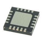
ICGOO电子元器件商城为您提供ADP1050ACPZ-R7由Analog设计生产,在icgoo商城现货销售,并且可以通过原厂、代理商等渠道进行代购。 ADP1050ACPZ-R7价格参考¥44.56-¥75.12。AnalogADP1050ACPZ-R7封装/规格:PMIC - 电源控制器,监视器, Power Supply Controller Power Supply Controller/Monitor 20-LFCSP-WQ (4x4)。您可以下载ADP1050ACPZ-R7参考资料、Datasheet数据手册功能说明书,资料中有ADP1050ACPZ-R7 详细功能的应用电路图电压和使用方法及教程。
ADP1050ACPZ-R7 是 Analog Devices Inc. 生产的一款 PMIC(电源管理集成电路),主要用作电源控制器和监视器。这款器件具有多种应用场景,尤其适用于需要高精度、高效能电源管理和监控的复杂系统。

 应用场景:

1. 通信基础设施:
   - ADP1050ACPZ-R7 可用于基站、路由器等通信设备中,提供稳定的电源管理和监控功能。它能够确保这些设备在各种工作条件下保持高性能和可靠性,特别是在高温、高压等恶劣环境下。

2. 工业自动化:
   - 在工业控制系统中,如PLC(可编程逻辑控制器)、伺服驱动器等,ADP1050ACPZ-R7 可以精确控制和监测电源,确保系统的稳定运行。它还支持多种通信协议,便于与上位机或其他设备进行数据交换。

3. 数据中心和服务器:
   - 数据中心和服务器对电源的要求非常高,ADP1050ACPZ-R7 可以提供高效的电源管理,减少能源浪费,同时通过实时监控电源状态,确保服务器的可靠性和稳定性。

4. 医疗设备:
   - 医疗设备如监护仪、超声波设备等需要高精度的电源管理,ADP1050ACPZ-R7 可以满足这些需求,确保设备在长时间运行中保持稳定性能,并且能够在异常情况下及时报警或采取保护措施。

5. 汽车电子:
   - 在现代汽车中,ADP1050ACPZ-R7 可用于车载信息娱乐系统、驾驶辅助系统等,提供可靠的电源管理和监控功能。它还能适应汽车环境中复杂的电气环境,确保系统的安全性和可靠性。

6. 消费电子:
   - 高端消费电子产品如笔记本电脑、平板电脑等也可以使用 ADP1050ACPZ-R7 来优化电源管理,延长电池寿命,提高用户体验。

总之,ADP1050ACPZ-R7 以其高效、精准的电源管理和监控能力,在多个领域中发挥着重要作用,广泛应用于通信、工业、医疗、汽车和消费电子等行业。
| 参数 | 数值 |
| 产品目录 | 集成电路 (IC)半导体 |
| 描述 | IC DGTL PWR MGMT 20LFCSP开关控制器 Controller ISO Power w/ PMBus Interface |
| 产品分类 | |
| 品牌 | Analog Devices |
| 产品手册 | |
| 产品图片 | |
| rohs | 符合RoHS无铅 / 符合限制有害物质指令(RoHS)规范要求 |
| 产品系列 | 电源管理 IC,开关控制器 ,Analog Devices ADP1050ACPZ-R7- |
| mouser_ship_limit | 该产品可能需要其他文件才能进口到中国。 |
| 数据手册 | |
| 产品型号 | ADP1050ACPZ-R7 |
| PCN组件/产地 | |
| 上升时间 | 3.5 ns |
| 下降时间 | 1.5 ns |
| 产品 | Digital Power Managers |
| 产品种类 | 开关控制器 |
| 供应商器件封装 | 20-LFCSP-WQ(4x4) |
| 关闭 | Yes |
| 其它名称 | ADP1050ACPZ-R7TR |
| 包装 | 带卷 (TR) |
| 同步管脚 | Yes |
| 商标 | Analog Devices |
| 安装类型 | 表面贴装 |
| 安装风格 | SMD/SMT |
| 封装 | Reel |
| 封装/外壳 | 20-WFQFN 裸露焊盘,CSP |
| 封装/箱体 | LFCSP-20 |
| 工作温度 | -40°C ~ 125°C |
| 工作电源电压 | 3.3 V |
| 工作电源电流 | 28.5 mA |
| 工厂包装数量 | 1500 |
| 应用 | 电源控制器/监控器 |
| 开关频率 | 200 MHz |
| 拓扑结构 | Full-Bridge |
| 最大工作温度 | + 125 C |
| 最小工作温度 | - 40 C |
| 标准包装 | 1,500 |
| 电压-电源 | 3 V ~ 3.6 V |
| 电压-输入 | 0 V ~ 1.6 V |
| 电流-电源 | 28.5mA |
| 类型 | Digital Controller |
| 绝缘 | Non-Isolated |
| 输入电压 | 1 V |
| 输出电压 | 0.4 V |
| 输出电流 | 10 mA |
| 输出端数量 | 4 Output |
| 输出类型 | Programmable |
| 配用 | /product-detail/zh/ADP1050DC1-EVALZ/ADP1050DC1-EVALZ-ND/4810884 |


- 商务部:美国ITC正式对集成电路等产品启动337调查
- 曝三星4nm工艺存在良率问题 高通将骁龙8 Gen1或转产台积电
- 太阳诱电将投资9.5亿元在常州建新厂生产MLCC 预计2023年完工
- 英特尔发布欧洲新工厂建设计划 深化IDM 2.0 战略
- 台积电先进制程称霸业界 有大客户加持明年业绩稳了
- 达到5530亿美元!SIA预计今年全球半导体销售额将创下新高
- 英特尔拟将自动驾驶子公司Mobileye上市 估值或超500亿美元
- 三星加码芯片和SET,合并消费电子和移动部门,撤换高东真等 CEO
- 三星电子宣布重大人事变动 还合并消费电子和移动部门
- 海关总署:前11个月进口集成电路产品价值2.52万亿元 增长14.8%


PDF Datasheet 数据手册内容提取
Digital Controller for Isolated Power Supply with PMBus Interface Data Sheet ADP1050 FEATURES GENERAL DESCRIPTION Versatile digital voltage mode controller The ADP1050 is an advanced digital controller with a PMBus™ High speed input voltage feedforward control interface targeting high density, high efficiency dc-to-dc power 4 pulse-width modulation (PWM) logic outputs with 625 ps conversion. This controller implements voltage mode control resolution with high speed, input voltage feedforward operation for Switching frequency: 49 kHz to 625 kHz enhanced transient and noise performance. The ADP1050 has Frequency synchronization as slave device four programmable pulse-width modulation (PWM) outputs Pulse skipping power saving mode capable of controlling most high efficiency power supply Prebias startup topologies, with the added control of synchronous rectification (SR). Conditional overvoltage protection The ADP1050 implements several features to enable a robust Extensive fault detection and protection system of parallel and redundant operation for customers who PMBus compliant require high availability. The device provides synchronization, Graphical user interface (GUI) for ease of programming prebias startup, and conditional overvoltage techniques to On-board EEPROM for programming and data storage identify and safely shut down an erroneous power supply in Available in a 20-lead, 4 mm × 4 mm LFCSP parallel operation mode. −40°C to +125°C operating temperature The ADP1050 is based on flexible state machine architecture APPLICATIONS and is programmed using an intuitive graphical user interface High density, isolated dc-to-dc power supplies (GUI). The easy to use GUI reduces design cycle time and Intermediate bus converters results in a robust, hardware coded system loaded into the built- High availability parallel power systems in EEPROM. The small size (4 mm × 4 mm) of the LFCSP Server, storage, industrial, networking, and communications package makes the ADP1050 ideal for ultracompact, isolated infrastructure dc-to-dc power module or embedded power designs. TYPICAL APPLICATIONS CIRCUIT DC INPUT LOAD ADP3624 or ADP3654 SR1 SR2 VF OVP VS+ VS– CS1 OUTA ADuM3221 OUTB ADP1050 SYNI/FLGI VDD RESADDRTDVCORE PG/ALT CTRL SDA SCL AGND PMBus 12039-006 Figure 1. Rev. A Document Feedback Information furnished by Analog Devices is believed to be accurate and reliable. However, no responsibility is assumed by Analog Devices for its use, nor for any infringements of patents or other One Technology Way, P.O. Box 9106, Norwood, MA 02062-9106, U.S.A. rights of third parties that may result from its use. Specifications subject to change without notice. No license is granted by implication or otherwise under any patent or patent rights of Analog Devices. Tel: 781.329.4700 ©2014 Analog Devices, Inc. All rights reserved. Trademarks and registered trademarks are the property of their respective owners. Technical Support www.analog.com
ADP1050 Data Sheet TABLE OF CONTENTS Features .............................................................................................. 1 PMBus Protection Commands ................................................. 30 Applications ....................................................................................... 1 Manufacturer Specific Protection Commands ....................... 32 General Description ......................................................................... 1 Manufacturer Specific Protection Responses ......................... 34 Typical Applications Circuit ............................................................ 1 Power Supply Calibration and Trim ............................................ 35 Revision History ............................................................................... 3 I Trim (CS1 Trim).................................................................... 35 IN Specifications ..................................................................................... 4 V Trim (VS Trim) ................................................................. 35 OUT Timing Diagram ........................................................................... 7 V Trim (VF Gain Trim) .......................................................... 35 IN Absolute Maximum Ratings ............................................................ 8 RTD and OTP Trim ................................................................... 36 Thermal Resistance ...................................................................... 8 Layout Guidelines ........................................................................... 37 Soldering ........................................................................................ 8 CS1 Pin ........................................................................................ 37 ESD Caution .................................................................................. 8 VS+ and VS− Pins ...................................................................... 37 Pin Configuration and Function Descriptions ............................. 9 VDD Pin ...................................................................................... 37 Typical Performance Characteristics ........................................... 11 VCORE Pin ................................................................................. 37 Theory of Operation ...................................................................... 12 RES Pin ........................................................................................ 37 PWM Outputs (OUTA, OUTB, SR1, and SR2) ...................... 13 SDA and SCL Pins ...................................................................... 37 Synchronous Rectification ........................................................ 13 Exposed Pad ................................................................................ 37 PWM Modulation Limit and 180° Phase Shift ....................... 14 RTD Pin ....................................................................................... 37 Frequency Synchronization ...................................................... 14 AGND Pin ................................................................................... 37 Output Voltage Sense and Adjustment .................................... 16 PMBus/I2C Communication ......................................................... 38 Digital Compensator .................................................................. 17 PMBus Features .......................................................................... 38 Closed-Loop Input Voltage Feedforward Control and Overview ..................................................................................... 38 VF Sense ...................................................................................... 18 PMBus/I2C Address ................................................................... 38 Open-Loop Input Voltage Feedforward Operation ............... 19 Data Transfer............................................................................... 38 Open-Loop Operation ............................................................... 19 General Call Support ................................................................. 40 CS1 Current Sense (CS1 Pin) .................................................... 20 10-Bit Addressing ....................................................................... 40 Soft Start and Shutdown ............................................................ 20 Fast Mode .................................................................................... 40 Volt-Second Balance Control .................................................... 22 Fault Conditions ......................................................................... 40 Pulse Skipping ............................................................................. 23 Timeout Conditions ................................................................... 40 Prebias Startup ............................................................................ 23 Data Transmission Faults .......................................................... 40 VDD and VCORE ...................................................................... 23 Data Content Faults ................................................................... 41 Chip Password ............................................................................ 24 EEPROM ......................................................................................... 42 Power Monitoring, Flags, and Fault Responses .......................... 25 EEPROM Features ...................................................................... 42 Flags .............................................................................................. 25 EEPROM Overview ................................................................... 42 Voltage Readings ........................................................................ 28 EEPROM Password .................................................................... 42 Current Readings ........................................................................ 28 Page Erase Operation ................................................................. 42 Power Readings ........................................................................... 28 Read Operation (Byte Read and Block Read) ........................ 43 Duty Cycle Reading .................................................................... 28 Write Operation (Byte Write and Block Write) ..................... 43 Switching Frequency Reading .................................................. 28 Downloading EEPROM Settings to Internal Registers ......... 44 Temperature Reading ................................................................. 29 Saving Register Settings to the EEPROM ............................... 44 Temperature Linearization Scheme ......................................... 30 EEPROM CRC Checksum ........................................................ 44 Rev. A | Page 2 of 92
Data Sheet ADP1050 GUI Software ................................................................................... 45 Temperature Sense and Protection Setting Registers ............. 79 PMBus Command Set .................................................................... 46 Digital Compensator and Modulation Setting Registers ....... 80 Manufacturer Specific Extended Command List ....................... 49 PWM Outputs Timing Registers .............................................. 83 PMBus Command Descriptions ................................................... 51 Volt-Second Balance Control Registers ................................... 85 Basic PMBus Commands ........................................................... 51 Duty Cycle Reading Setting Registers ...................................... 86 Manufacturer Specific Extended Commands Descriptions ...... 70 Other Register Settings............................................................... 86 Flag Configuration Registers ..................................................... 70 Manufacturer Specific Fault Flag Registers ............................. 89 Soft Start and Software Reset Registers .................................... 72 Manufacturer Specific Value Reading Registers ..................... 91 Blanking and PGOOD Setting Registers .................................. 73 Outline Dimensions ........................................................................ 92 Switching Frequency and Synchronization Registers ............ 75 Ordering Guide ........................................................................... 92 Current Sense and Limit Setting Registers .............................. 76 Voltage Sense and Limit Setting Registers ............................... 78 REVISION HISTORY 6/14—Rev. 0 to Rev. A Changes to Table 2 ............................................................................ 8 Changes to Pin 1, Table 4 ................................................................. 9 Changes to VOUT_COMMAND Section ................................... 53 Change to Bit 7, Table 164 .............................................................. 89 1/14—Revision 0: Initial Version Rev. A | Page 3 of 92
ADP1050 Data Sheet SPECIFICATIONS V = 3.0 V to 3.6 V, T = −40°C to +125°C, unless otherwise noted. FSR = full-scale range. DD J Table 1. Parameter Symbol Min Typ Max Unit Test Conditions/Comments SUPPLY Supply Voltage V 3.0 3.3 3.6 V 2.2 μF capacitor connected to AGND DD Supply Current I 28.5 33 mA Normal operation; PWM pins unloaded DD I + 6 mA During EEPROM programming DD 50 100 μA Shutdown; V below undervoltage DD lockout (UVLO) threshold POWER-ON RESET Power-On Reset 3.0 V V rising DD UVLO Threshold 2.75 2.85 2.97 V V falling DD UVLO Hysteresis 35 mV OVLO Threshold 3.7 3.9 4.1 V OVLO Debounce 2 μs VDD_OV flag debounce set to 2 μs 500 μs VDD_OV flag debounce set to 500 μs VCORE PIN Output Voltage V 2.45 2.6 2.75 V 330 nF capacitor connected to AGND CORE OSCILLATOR AND PLL PLL Frequency 190 200 210 MHz RES input = 10 kΩ (±0.1%) Digital PWM Resolution 625 ps OUTA, OUTB, SR1, SR2 PINS Output Low Voltage V 0.4 V I = 10 mA OL OH Output High Voltage V V − 0.4 V I = −10 mA OH DD OL Rise Time t 3.5 ns C = 50 pF R LOAD Fall Time t 1.5 ns C = 50 pF F LOAD Output Source Current I −10 mA OL Output Sink Current I 10 mA OH VS+, VS− VOLTAGE SENSE PINS Input Voltage Range V 0 1 1.6 V Differential voltage from VS+ to VS− IN Leakage Current 1.0 μA VS Accurate ADC Valid Input Voltage Range 0 1.6 V ADC Clock Frequency 1.56 MHz Register Update Rate 10 ms Measurement Resolution 12 Bits Measurement Accuracy Factory trimmed at 1.0 V −5 +5 % FSR 0% to 100% of input voltage range −80 +80 mV −2 +2 % FSR 10% to 90% of input voltage range −32 +32 mV −1.0 +1.0 % FSR 900 mV to 1.1 V −16 +16 mV Temperature Coefficient 70 ppm/°C Voltage Differential from VS− to AGND −200 +200 mV VS High Speed ADC Equivalent Sampling Frequency f f kHz SAMP SW Equivalent Resolution 6 Bits f = 390.5 kHz SW Dynamic Range ±25 mV Regulation voltage = 0 mV to 1.6 V VS UVP Digital Comparator Triggers VOUT_UV_FAULT flag Threshold Accuracy −2 +2 % FSR 10% to 90% of input voltage range Comparator Update Speed 82 µs Rev. A | Page 4 of 92
Data Sheet ADP1050 Parameter Symbol Min Typ Max Unit Test Conditions/Comments OVP PIN Triggers VOUT_OV_FAULT flag Leakage Current 1.0 µA OVP Comparator Voltage Range 0.75 1.5 V Differential voltage from OVP to VS− Threshold Accuracy −1.6 +1 +1.6 % 0.75 V to 1.5 V voltage range Propagation Delay (Latency) 61 85 ns Debounce time not included VF VOLTAGE SENSE PIN Input Voltage Range V 0 1 1.6 V Voltage from VF to AGND IN Leakage Current 1.0 µA General ADC Valid Input Voltage Range 0 1.6 V ADC Clock Frequency 1.56 MHz Register Update Rate 1.31 ms Measurement Resolution 11 Bits Measurement Accuracy −2 +2 % FSR 10% to 90% of input voltage range −32 +32 mV −5 +5 % FSR 0% to 100% of input voltage range −80 +80 mV VF UVP Digital Comparator Triggers VIN_LOW or VIN_UV_FAULT flag Threshold Accuracy Based on VF general ADC parameter values Comparator Update Speed 1.31 ms Feedforward ADC Input Voltage Range V 0.5 1 1.6 V IN Resolution 11 Bits Sampling Period 10 μs CS1 CURRENT SENSE PIN Input Voltage Range V 0 1 1.6 V Voltage from CS1 to AGND IN Source Current −1.2 −0.35 µA CS1 ADC Valid Input Voltage Range 0 1.6 V ADC Clock Frequency 1.56 MHz Register Update Rate 10 ms Measurement Resolution 12 Bits Measurement Accuracy −2 +2 % FSR 10% to 90% of input voltage range −32 +32 mV −5 +5 % FSR 0% to 100% of input voltage range −80 +80 mV CS1 OCP Comparator Triggers internal CS1_OCP flag Reference Accuracy 1.185 1.2 1.215 V When set to 1.2 V 0.235 0.25 0.265 V When set to 0.25 V Propagation Delay (Latency) 65 105 ns Debounce/blanking time not included CS31 Measurement and Digital Comparator Triggers CS3_OC_FAULT flag Register Update Rate 10 ms Comparator Speed 10 ms Rev. A | Page 5 of 92
ADP1050 Data Sheet Parameter Symbol Min Typ Max Unit Test Conditions/Comments RTD TEMPERATURE SENSE PIN Input Voltage Range V 0 1.6 V Voltage from RTD to AGND IN Source Current Factory default setting Register 0xFE2D = 0xE6 44.6 46 47.3 μA Register 0xFE2D = 0xB0 38.6 40 42 μA Register 0xFE2D = 0x80 28.6 30 31.8 μA Register 0xFE2D = 0x40 18.6 20 21.6 μA Register 0xFE2D = 0x00 9.1 10 11 μA RTD ADC Valid Input Voltage Range V 0 1.6 V IN ADC Clock Frequency 1.56 MHz Register Update Rate 10 ms Measurement Resolution 12 Bits Measurement Accuracy −0.3 +0.45 % FSR 2% to 20% of the input voltage range −4.8 +7.2 mV −2 +2 % FSR 0% to 100% of the input voltage range −80 +80 mV OTP Digital Comparator Triggers OT_FAULT flag Threshold Accuracy −0.9 +0.25 % FSR T = 85°C with 100 kΩ||16.5 kΩ −14.4 +4 mV −0.5 +1.1 % FSR T = 100°C with 100 kΩ||16.5 kΩ −8 +17.6 mV Comparator Update Speed 10 ms Temperature Readings According to Source current is set to 46 µA Internal Linearization Scheme (Register 0xFE2D = 0xE6); NTC R25 = 100 kΩ (1%); beta = 4250 (1%); R = 16.5 kΩ (1%) EXT 7 °C 25°C to 100°C 5 °C 100°C to 125°C PG/ALT (OPEN-DRAIN) PIN Output Low Level V 0.4 V Sink current = 10 mA OL CTRL PIN Input Low Level V 0.4 V IL Input High Level V V − 0.8 V IH DD Leakage Current 1.0 µA SYNI/FLGI PIN Input Low Level V 0.4 V IL Input High Level V V − 0.8 V IH DD Synchronization Range % of Internal Clock t 90 110 % SYNC Period SYNI Positive Pulse Width 360 ns External clock applied on the SYNI/FLGI pin SYNI Negative Pulse Width 360 ns External clock applied on the SYNI/FLGI pin SYNI Period Drift 280 ns Period drift between two consecutive external clocks Leakage Current 1.0 µA SDA AND SCL PINS Input Low Voltage V 0.8 V IL Input High Voltage V V − 0.8 V IH DD Output Low Voltage V 0.4 V Sink current = 3 mA OL Leakage Current −5 +5 µA Rev. A | Page 6 of 92
Data Sheet ADP1050 Parameter Symbol Min Typ Max Unit Test Conditions/Comments SERIAL BUS TIMING See Figure 2 Clock Operating Frequency 10 100 400 kHz Glitch Immunity 50 ns Bus Free Time t 1.3 µs Between stop and start conditions BUF Start Setup Time t 0.6 µs Repeated start condition setup time SU;STA Start Hold Time t 0.6 µs Hold time after repeated start condition; HD;STA after this period, the first clock is generated Stop Setup Time t 0.6 µs SU;STO SDA Setup Time t 100 ns SU;DAT SDA Hold Time t 125 ns For readback HD;DAT 300 ns For write SCL Low Timeout t 25 35 ms TIMEOUT SCL Low Time t 0.6 µs LOW SCL High Time t 0.6 µs HIGH SCL Low Extended Time t 25 ms LOW;SEXT SCL, SDA Rise Time t 20 300 ns R SCL, SDA Fall Time t 20 300 ns F EEPROM EEPROM Update Time 40 ms Time from the update command to completion of the EEPROM update Reliability Endurance2 10,000 Cycles T = 85°C J 1000 Cycles T = 125°C J Data Retention3 20 Years T = 85°C J 15 Years T = 125°C J 1 CS3 is an alternative output current reading that is calculated by the CS1 reading (representing input current), duty cycle, and the main transformer turns ratio. 2 Endurance is qualified as per JEDEC Standard 22, Method A117, and is measured at −40°C, +25°C, +85°C, and +125°C. 3 Retention lifetime equivalent at junction temperature as per JEDEC Standard 22, Method A117. TIMING DIAGRAM tR tF tLOW tHD;STA SCL tHIGH tSU;STA tSU;STO tHD;STA tHD;DAT tSU;DAT SDA PtBUFS S P 12039-002 Figure 2. Serial Bus Timing Diagram Rev. A | Page 7 of 92
ADP1050 Data Sheet ABSOLUTE MAXIMUM RATINGS THERMAL RESISTANCE Table 2. θ is specified for the worst-case conditions, that is, a device Parameter Rating JA soldered in a circuit board for surface-mount packages. Supply Voltage (Continuous) V 4.2 V DD Digital Pins (OUTA, OUTB, SR1, SR2, PG/ALT, −0.3 V to V + 0.3 V DD Table 3. Thermal Resistance SDA, SCL) to AGND Package Type θ θ Unit JA JC VS−, VS+, VF, OVP, RTD, ADD, CS1 to AGND −0.3 V to V + 0.3 V DD 20-Lead LFCSP 37.05 1.53 °C/W SYNI/FLGI, CTRL −0.3 V to V + 0.3 V DD Operating Temperature Range (T ) −40°C to +125°C A SOLDERING Storage Temperature Range −65°C to +150°C Junction Temperature 150°C It is important to follow the correct guidelines when laying out Peak Solder Reflow Temperature the printed circuit board (PCB) footprint for the ADP1050 and SnPb Assemblies (10 sec to 30 sec) 240°C for soldering the device onto the PCB. For detailed information RoHS-Compliant Assemblies (20 sec to 260°C about these guidelines, see the AN-772 Application Note, A Design 40 sec) and Manufacturing Guide for the Lead Frame Chip Scale Package ESD Charged Device Model 1.25 kV (LFCSP). ESD Human Body Model 5.0 kV ESD CAUTION Stresses at or above those listed under Absolute Maximum Ratings may cause permanent damage to the product. This is a stress rating only; functional operation of the product at these or any other conditions above those indicated in the operational section of this specification is not implied. Operation beyond the maximum operating conditions for extended periods may affect product reliability. Rev. A | Page 8 of 92
Data Sheet ADP1050 PIN CONFIGURATION AND FUNCTION DESCRIPTIONS D DDSND TDEGD RARAV 09876 21111 OVP 1 15 VCORE VS– 2 ADP1050 14 PG/ALT VS+ 3 TOP VIEW 13 CTRL VF 4 (Not to Scale) 12 SDA CS1 5 11 SCL 61RS72RS8ATUO9BTUO01IGLF/IN 12039-124 Y S NOTES 1. THE ADP1050 HAS AN EXPOSED THERMAL PAD ON THE UNDERSIDE OF THE PACKAGE. FOR INCREASED RELIABILITY OF THE SOLDER JOINTS AND MAXIMUM THERMAL CAPABILITY, IT IS RECOMMENDED THAT THE EXPOSED PAD BE SOLDERED TO THE PCB AGND PLANE. Figure 3. Pin Configuration Table 4. Pin Function Descriptions Pin No. Mnemonic Description 1 OVP Overvoltage Protection. This signal is used as redundant overvoltage protection. This signal is referred to AGND. 2 VS− Inverting Voltage Sense Input. This pin is the connection for the ground line of the power rail. Provide a low ohmic connection to AGND. To allow trimming, it is recommended that the resistor divider on this input have a tolerance specification of ≤0.5%. 3 VS+ Noninverting Voltage Sense Input. This signal is referred to VS−. To allow trimming, it is recommended that the resistor divider on this input have a tolerance specification of ≤0.5%. 4 VF Voltage Feedforward. Three optional functions can be implemented with this pin: feedforward, primary side input voltage sensing, and input voltage UVLO protection. The pin is connected upstream of the output inductor through a resistor divider network. The nominal voltage at this pin is 1 V. This signal is referred to AGND. 5 CS1 Primary Side Current Sense Input. This pin is connected to the primary side current sensing ADC and to the cycle- by-cycle current-limit comparator. This signal is referred to AGND. To allow trimming, it is recommended that the resistors on this input have a tolerance specification of ≤0.5%. If this pin is not used, connect it to AGND. 6 SR1 PWM Logic Output Drive. This pin can be disabled when not in use. This signal is referred to AGND. 7 SR2 PWM Logic Output Drive. This pin can be disabled when not in use. This signal is referred to AGND. 8 OUTA PWM Logic Output Drive. This pin can be disabled when not in use. This signal is referred to AGND. 9 OUTB PWM Logic Output Drive. This pin can be disabled when not in use. This signal is referred to AGND. 10 SYNI/FLGI Synchronization Signal Input (SYNI)/External Signal Input to Generate a Flag Condition (FLGI). If this pin is not used, connect it to AGND. 11 SCL I2C/PMBus Serial Clock Input and Output (Open Drain). This signal is referred to AGND. 12 SDA I2C/PMBus Serial Data Input and Output (Open Drain). This signal is referred to AGND. 13 CTRL PMBus Control Signal. It is recommended that a 1 nF capacitor be connected from the CTRL pin to AGND for noise debounce and decoupling. This signal is referred to AGND. 14 PG/ALT Power-Good Output (Open Drain)(PG)/Active Low SMBus ALERT Signal (ALT). Connect this pin to VDD using a pull- up resistor (typically 2.2 kΩ). The power-good signal is referred to AGND. For information about the SMBus specification, see the PMBus Features section. 15 VCORE Output of the 2.6 V Regulator. Connect a decoupling capacitor of at least 330 nF from this pin to AGND, as close as possible to the ADP1050 to minimize the PCB trace length. It is recommended that this pin not be used as a reference or to generate other logic levels using resistive dividers. 16 VDD Positive Supply Input. Voltage of 3.0 V to 3.6 V. This signal is referred to AGND. Connect a 2.2 μF decoupling capacitor from this pin to AGND, as close as possible to the ADP1050 to minimize the PCB trace length. 17 AGND Common Analog Ground. The internal analog circuitry ground and the digital circuitry ground are star connected to this pin through bonding wires. 18 RES Resistor Input. This pin sets the internal reference for the internal PLL frequency. Connect a 10 kΩ resistor (±0.1%) from this pin to AGND. This signal is referred to AGND. 19 ADD Address Select Input. This pin is used to program the I2C/PMBus address. Connect a resistor from ADD to AGND. This signal is referred to AGND. Rev. A | Page 9 of 92
ADP1050 Data Sheet Pin No. Mnemonic Description 20 RTD Thermistor Input. Place a thermistor (R25 = 100 kΩ (1%), beta = 4250 (1%)) in parallel with a 16.5 kΩ (1%) resistor and a 1 nF filtering capacitor. This pin is referred to AGND. If this pin is not used, connect it to AGND. EP Exposed Pad. The ADP1050 has an exposed thermal pad on the underside of the package. For increased reliability of the solder joints and maximum thermal capability, it is recommended that the exposed pad be soldered to the PCB AGND plane. Rev. A | Page 10 of 92
Data Sheet ADP1050 TYPICAL PERFORMANCE CHARACTERISTICS 2.5 2.5 MAX SPEC MAX SPEC 2.0 2.0 R) 1.5 R) 1.5 S S %F 1.0 %F 1.0 CY ( 0.5 MEAN MAX CY ( 0.5 MEAN MAX A A R R U 0 U 0 C C C C A–0.5 A–0.5 DC MIN DC MIN A–1.0 A–1.0 S D V T –1.5 R–1.5 MIN SPEC –2.0 –2.0 MIN SPEC –2.5–60 –40 –20 0 TE2M0PERA40TURE60(°C) 80 100 120 140 12039-007 –2.5–60 –40 –20 0 TE2M0PERA40TURE60(°C) 80 100 120 140 12039-011 Figure 4. VS ADC Accuracy vs. Temperature (From 10% to 90% of FSR) Figure 7. RTD ADC Accuracy vs. Temperature (From 10% to 90% of FSR) 2.5 1.23 MAX SPEC 2.0 V) E (1.22 1.5 C ACCURACY (%FSR)–001...5500 MEAN MAX PARATOR REFEREN11..2210 MEAN MAMXI NSPEC MAX C M D MIN O1.19 VFA–1.0 CP C MIN SPEC –1.5 O MIN SPEC S1 1.18 –2.0 C –2.5–60 –40 –20 0 TE2M0PERA40TURE60(°C) 80 100 120 140 12039-008 1.17–60 –40 –20 0 TE2M0PERA40TURE60(°C) 80 100 120 140 12039-012 Figure 5. VF ADC Accuracy vs. Temperature (From 10% to 90% of FSR) Figure 8. CS1 OCP Comparator Reference vs. Temperature (1.2 V Reference) 2.5 0.280 MAX SPEC 2.0 V) E ( RACY (%FSR) 101...550 MEAN MAX OR REFERENC0.265 MEAN MAX SPEC MAX CU 0 AT0.250 C R ADCA––01..50 MIN COMPA MIN S1 P 0.235 C–1.5 OC MIN SPEC 1 S –2.0 C MIN SPEC –2.5–60 –40 –20 0 TE2M0PERA40TURE60(°C) 80 100 120 140 12039-009 0.220–60 –40 –20 0 TE2M0PERA40TURE60(°C) 80 100 120 140 12039-113 Figure 6. CS1 ADC Accuracy vs. Temperature (From 10% to 90% of FSR) Figure 9. CS1 OCP Comparator Reference vs. Temperature (0.25 V Reference) Rev. A | Page 11 of 92
ADP1050 Data Sheet THEORY OF OPERATION The ADP1050 is designed as a flexible, easy to use, digital power up to four programmable PWM outputs for control of primary supply controller. The ADP1050 integrates the typical functions side FET drivers and synchronous rectification FET drivers. This that are needed to control a power supply, such as programmability allows many generic and specific switching power supply topologies to be realized. • Output voltage sense and feedback • Voltage feedforward control Conventional power supply housekeeping features, such as input • Digital loop filter compensation voltage sense, output voltage sense, primary side current sense, • PWM generation and secondary side current sense, are included. An extensive set • Current, voltage, and temperature sense of protections is included, such as overvoltage protection (OVP), overcurrent protection (OCP), overtemperature protection (OTP), • Housekeeping and I2C/PMBus interface and undervoltage protection (UVP). • Calibration and trimming These features are programmable through the I2C/PMBus The main function of controlling the output voltage is performed digital bus interface. This interface is also used for calibrations. by the feedback ADCs, the digital loop compensator, and the Other information, such as input current, output current, and digital PWM engine. fault flags, is also available through this digital bus interface. The feedback ADCs feature a patented multipath architecture, The internal EEPROM can store all programmed values and allows with a high speed, low resolution (fast and coarse) ADC and a standalone control without a microcontroller. A free, downloadable low speed, high resolution (slow and accurate) ADC. The ADC GUI is available that provides all the necessary software to program outputs are combined to form a high speed and high resolution the ADP1050. To obtain the latest GUI software and a user guide, feedback path. Loop compensation is implemented using the visit http://www.analog.com/digitalpower. digital compensator. This proportional, integral, derivative (PID) The ADP1050 operates from a single 3.3 V power supply and is compensator is implemented in the digital domain to allow easy specified from −40°C to +125°C. programming of filter characteristics, which is of great value in customizing and debugging designs. The PWM engine generates CS1 VF VS+ VS– V V 5 2 2 1. 0. VREF ADC ADC ADC OVP OUTA DAC OUTB PWM ADC RTD ENGINE DIGITAL CORE SR1 ADD 8kB OSC SR2 EEPROM RES PMBus AGND UVLO VDD LDO SYNI/FLGI SCL SDA CTRL PG/ALT VCORE 12039-013 Figure 10. Functional Block Diagram Rev. A | Page 12 of 92
Data Sheet ADP1050 PWM OUTPUTS (OUTA, OUTB, SR1, AND SR2) See the PWM Outputs Timing Registers section for additional information about the PWM timings. The PWM outputs are used for control of the primary side drivers and the synchronous rectifier drivers. They can be used for several SYNCHRONOUS RECTIFICATION topologies, including hard-switched full bridge, half bridge, push SR1 and SR2 are recommended for use as the PWM control signals pull, two-switch forward, active clamp forward, and interleaved when synchronous rectification is in use. These PWM signals can buck. Delays between rising and falling edges can be individually be configured much like the other PWM outputs. programmed. Special care must be taken to avoid shootthrough and An optional soft start can be applied to the synchronous rectifier cross conduction. It is recommended that the ADP1050 GUI (SR) PWM outputs. The SR soft start can be programmed using software be used to program these outputs. Register 0xFE08[4:0]. Figure 11 shows an example configuration to drive an active clamp • When the SR soft start is disabled (Register 0xFE08[1:0] = 00), forward topology with synchronous rectification. The QA, QB, the SR signals are immediately turned on to their modulated QSR1, and QSR2 switches are driven separately by the PWM outputs PWM duty cycle values. (OUTA, OUTB, SR1, and SR2). Figure 12 shows an example of the PWM settings in the GUI for the power stage shown in Figure 11. • When the SR soft start is enabled (Register 0xFE08[1:0] = 11), the SR1 and SR2 rising edges move left from the t + RX The PWM outputs are all synchronized with each other. Therefore, t position to the t + t position in steps MODU_LIMIT RX MODULATION when reprogramming more than one of these outputs, it is that are set in Register 0xFE08[3:2]. t represents the rising RX important to first update all of the registers and then latch the edge timing of SR1 (t ) and the rising edge timing of SR2 R5 information into the shadow registers at one time. During the (t ) (see Figure 58); t represents the modulation R6 MODU_LIMIT reprogramming operation, the outputs are temporarily disabled. To limit defined in Register 0xFE3C (see Figure 57); t MODULATION ensure that the new PWM timings and the switching frequency represents the real-time modulation value. setting are programmed simultaneously, a special instruction is • The SR soft start is still applicable even if the SR1 and SR2 sent to the ADP1050 by setting Register 0xFE61[2:1] (the go outputs are not programmed to be modulated. When the SR commands). It is recommended that the PWM outputs not in use be soft start is enabled, the SR1 and SR2 rising edges move left disabled via Register 0xFE53[5:4] and Register 0xFE53[1:0]. from the t + t position to the t position in steps RX MODU_LIMIT RX that are set in Register 0xFE08[3:2]. DC INPUT QSR2 QSR1 DRIVER QA QB SR1 SR2 OUTA ISDORLIVAETRED OUTB 12039-120 Figure 11. PWM Assignment for Active Clamp Forward Topology with Synchronous Rectification 12039-121 Figure 12. PWM Settings for Active Clamp Forward Topology with Synchronous Rectification Using the ADP1050 GUI Rev. A | Page 13 of 92
ADP1050 Data Sheet The advantage of the SR soft start is that it minimizes the output The modulated edges cannot go beyond one switching cycle. To voltage undershoot that occurs when the SR FETs are turned on extend the modulation range for some applications, the 180° without a soft start. The advantage of turning the SRx signals phase shift can be enabled, using Register 0xFE3B[5:4] and completely on immediately is that they can help minimize the Register 0xFE3B[1:0]. When the 180° phase shift is disabled, the voltage transient caused during a load step. rising edge timing and the falling edge timing are referred to the start of the switching cycle (see t and t in Figure 13). When the Using Register 0xFE08[4], the SR soft start can be programmed to RX FX 180° phase shift is enabled, the rising edge timing and the falling occur only once (the first time that the SRx signals are enabled) or edge timing are referred to half of the switching cycle (see t and every time that the SRx signals are enabled. RY t in Figure 13, which are referred to t/2). Therefore, when the FY S When programming the ADP1050 to use the SR soft start, ensure 180° phase shift is disabled, the edges are always located between t 0 the correct operation of this function by setting the falling edge of and t. When the 180° phase shift is enabled, the edges are located S SR1 (t ) to a lower value than the rising edge of SR1 (t ) and setting F5 R5 between t/2 and 3t/2. S S the falling edge of SR2 (t ) to a lower value than the rising edge of F6 The 180° phase shift function can be used to extend the maximum SR2 (t ). During the SR soft start, the rising edges of SRx move R6 duty cycle in a multiphase, interleaved converter. Figure 14 shows gradually from the right side (the t + t position) to the RX MODU_LIMIT a dual phase, interleaved buck converter. The OUTB and SR1 left side to increase the duty cycle. PWM outputs can be programmed with a 180° phase shift with the The ADP1050 is well suited for dc-to-dc converters in isolated OUTA and SR2 PWM outputs. topologies. Every time a PWM signal crosses the isolation barrier, The ADP1050 GUI is recommended for evaluating this feature. a propagation delay is added because of the isolating components. Using Register 0xFE3A[5:0], an adjustable delay (0 ns to 315 ns in steps of 5 ns) can be programmed to move both SR1 and SR2 later in time to compensate for the added propagation delay. In this way, DC LOAD INPUT DRIVER all the PWM edges can be aligned (see Figure 58). PWM MODULATION LIMIT AND 180° PHASE SHIFT The modulation limit register (Register 0xFE3C) can be programmed to apply a maximum modulation limit to any PWM signal, thus limiting the modulation range of any PWM output. If modulation DRIVER is enabled, the maximum modulation limit is applied to all PWM outputs collectively. This limit, t , is the maximum time MODU_LIMIT variation for the modulated edges from the default timing, following tshetet icnogn ffoigru trheed m minoidmuulamtio dnu tdyi rceycctlieo nlim (siet.e T Fhigeurerfeo r1e3, )t.h Teh uesreer ims nuost OUTA SR2 OUTB SR1 12039-118 Figure 14. Dual Phase, Interleaved Buck Converter Controlled by the ADP1050 set the rising edges and falling edges based on the case with the least modulation. FREQUENCY SYNCHRONIZATION The ADP1050 can be programmed as a slave device to use the tMODU_LIMIT SYNI/FLGI pin signal as the reference to synchronize the internal OUTX tRX programmed PWM clock with an external clock. tFX The period of the external clock that is applied at the SYNI/FLGI pin tMODU_LIMIT must be in the range of 90% to 110% of the period of the internal OUTY tRY programmed PWM clock. The minimum pulse width of the SYNI signal is 360 ns. From the rising edge of the SYNI signal to the start t0 tS/2 tFY tS 3tS/2 12039-015 oref atlhize ei nintetrenralel acvloinckg ccyocnletr, othl ewriet his dai 7ff6e0re nnst pcroonptraoglalteirosn, addedlaityi.o Tnoa l Figure 13. Setting Modulation Limits delay time can be programmed using Register 0xFE11. Each least significant bit (LSB) in Register 0xFE3C corresponds to To achieve a smooth synchronization transition between asynchro- a different time step size, depending on the switching frequency nous operation and synchronous operation, there is a phase capture (see Table 137). If the ADP1050 is to control a dual-ended topology range bit for synchronization in Register 0xFE12[6] for capturing (such as full bridge, half bridge, or push pull), enable the dual-ended the phase of the external clock signal. The ADP1050 detects the topology mode using Register 0xFE13[6]. When dual-ended phase shift between the external clock signal and the internal clock topology mode is enabled, the modulation limit in each half cycle signal when synchronization is enabled. When the phase shift falls is half of the modulation value programmed by Register 0xFE3C. within the phase capture range, synchronization begins. Rev. A | Page 14 of 92
Data Sheet ADP1050 The ADP1050 synchronizes to the external clock frequency as returns to the internal clock set by the internal oscillator. follows: This interval is t or t, as shown in Figure 15. 1 3 This is the first synchronization unlock condition, called 1. After the synchronization function is enabled by Register Synchronization Unlocked Mode 1, in which the switching 0xFE12[3] and Register 0xFE12[0], the ADP1050 starts to frequency is out of range (range is 89% to approximately 114% detect the period of the external clock signal applied at the of the internal programmed frequency). SYNI/FLGI pin. 6. If the period of the external SYNI signal changes significantly 2. If all periods of the most recent 64 consecutive cycles of the (for example, if the period difference between contiguous cycles external clocks fall within 90% to 110% of the internal switching exceeds 280 ns), the ADP1050 takes the last valid external clock period, the ADP1050 uses the latest current cycle as the clock signal as the synchronization reference source. At the synchronization reference, and the period of the external clock same time, the phase shift between the synchronization is identified. This interval is t or t, as shown in Figure 15. 2 4 reference and the internal clock is detected. When the phase Otherwise, the ADP1050 discards this cycle and looks for the shift falls within the phase capture range, the PWM clock next cycle (frequency capture mode). returns to the internal clock set by the internal oscillator. 3. After the external clock period is determined, the ADP1050 This is the second synchronization unlock condition, called detects the phase shift between the external clock (plus the delay Synchronization Unlocked Mode 2, in which the phase shift time set by Register 0xFE11) and the internal PWM signal. If exceeds 280 ns. the phase shift is within the phase capture range, the internal and external clocks are synchronized (phase capture mode). Figure 15 shows the synchronization operation diagram. The 4. The PWM clock is synchronized with the external clock. Cycle- internal frequency, f , is the internal free-running frequency SW_INT by-cycle synchronization starts. of the ADP1050. Before the synchronization is locked, the 5. If the external clock signal is lost at any time, or if the period ADP1050 runs at f . The external frequency, f , is the SW_INT SW_EXT exceeds the minimum limit (89% of the internal programmed frequency of the external clock to which the ADP1050 must frequency) or the maximum limit (114% of the internal synchronize. After synchronization is locked, the ADP1050 runs programmed frequency), the ADP1050 takes the last valid at f . SW_EXT external clock signal as the synchronization reference source. The ADP1050 does not allow the switching frequency to cross the At the same time, the phase shift between the synchronization boundaries of 97.5 kHz, 195.5 kHz, or 390.5 kHz on-the-fly. reference and the internal clock is detected. When the phase Ensure that the external clock does not cross these boundaries. shift falls within the phase capture range, the PWM clock Otherwise, the internal switching frequency cannot be set within ±10% of these boundaries. EXTERNAL CLOCK FREQUENCY (fSW_EXT) INTERNAL CLOCK FREQUENCY (fSW_INT) fSW OPERATING SWITCHING FREQUENCY t1 t2 t3 t4 114% fSW_INT 110% fSW_INT fSW_INT 90% fSW_INT 89% fSW_INT UONNIT UONFIFT UONNIT TIME 12039-018 Figure 15. Synchronization Operation Rev. A | Page 15 of 92
ADP1050 Data Sheet ±3.125% SYNI ENABLE REG 0xFE12[3] 320ns SYNI DELAY PHASE CAPTURE SYNC OPERATION SSEYLNEIC/FTLIOGNI SYNI MODE DEBOUNCE TRIMEEG S 0ExTFTEI1N1G RARNEGGE 0SxEFLEE1C2[T6I]ON AS SLAVE DEVICE REG 0xFE12[0] SYNI/FLGI 0µs DEBOUNCE ±6.25% FLGI MODE REPGO 0LxAFREI1T2Y[2] DREEBGO U0NxFCEE1 T2[I1M]E RFELRGAE 0GSxIPFNOE FN0L3SA[E3G:2] 100µs DEBOUNCE 12039-017 Figure 16. Synchronization Configuration 12039-122 Figure 17. Edge Adjustment Reference During Synchronization To ensure a constant dead time before and after synchronization, Voltage Feedback Sensing (VS+ and VS− Pins) Register 0xFE6D and Register 0xFE6F can be set for edge adjustment The voltage sense point on the power rail requires an external referred to t/2 or t. For example, the falling edge of OUTA (t ) is S S F1 resistor divider (R1 and R2 in Figure 18) to bring the nominal referred to the ½ × t position, which means that the time difference S differential mode signal to 1 V between the VS+ and VS− pins (see between t and ½ × t is a constant during the synchronization F1 S Figure 18). This external resistor divider is necessary because the transition. Figure 17 shows an example of the edge adjustment VS ADC input range of the ADP1050 is 0 V to 1.6 V. When R1 reference settings in a full bridge topology. and R2 are known, the VOUT_SCALE_LOOP parameter can be OUTPUT VOLTAGE SENSE AND ADJUSTMENT calculated using the following equation: The output voltage sense and adjustment function is used for VOUT_SCALE_LOOP = R2/(R1 + R2) control, monitoring, and undervoltage protection of the remote In a 12 V system with resistor dividers of 11 kΩ and 1 kΩ, output voltage. VS− (Pin 2) and VS+ (Pin 3) are fully differential VOUT_SCALE_LOOP can be calculated as follows: inputs. The voltage sense point can be calibrated digitally to remove VOUT_SCALE_LOOP = 1 kΩ/(11 kΩ + 1 kΩ) = 0.08333 any errors due to external components. This calibration can be performed in the production environment, and the settings can be stored in the EEPROM of the ADP1050 (see the Power Supply LOAD Calibration and Trim section for more information). For voltage monitoring, the READ_VOUT output voltage command (Register 0x8B) is updated every 10 ms. The ADP1050 stores every ADC sample for 10 ms and then calculates the average value at the HIGH SPEED end of the 10 ms period. Therefore, if Register 0x8B is read at least DIGITAL ADC VS+ R1 COMPENSATOR every 10 ms, a true average value is obtained. The voltage information VS– R2 ACCURATE is available through the I2C/PMBus interface. ADC VOLTAGE SENSE REGISTERS The control loop of the ADP1050 features a patented multipath aArDchCitse:c at uhrieg.h T ahcec uoruatcpyu tA vDolCta agne dis a c hoingvhe rstpeede dsi mADulCta.n Tehoue scloy mbyp ltewteo VOUT_UV_FAULT FLAG VOUT_UV_FAULT_LIMIT 12039-020 signal is reconstructed and processed in the digital compensator Figure 18. Voltage Sense Configuration to provide a high performance and cost competitive solution. Rev. A | Page 16 of 92
Data Sheet ADP1050 Voltage Sense ADCs Output Voltage Adjustment Commands Two kinds of Σ-Δ ADCs are used in the ADP1050 feedback loop, In the ADP1050, the voltage data for commanding or reading as follows: the output voltage or related parameters is in linear data format. The linear format exponent is fixed at −10 decimal (see the • Low frequency (LF) ADC, running at 1.56 MHz VOUT_MODE command, Register 0x20, in Table 21). • High frequency (HF) ADC, running at 25 MHz The following three basic commands are used for setting the The Σ-Δ ADCs have a resolution of one bit and operate differently output voltage: from traditional flash ADCs. The equivalent resolution that is obtained depends on how long the output bit stream of the Σ-Δ • VOUT_COMMAND command (Register 0x21, Table 22) ADC is filtered. • VOUT_MARGIN_HIGH command (Register 0x25, Table 26) • VOUT_MARGIN_LOW command (Register 0x26, Table 27) The Σ-Δ ADCs also differ from Nyquist rate ADCs in that the quantization noise is not uniform across the frequency spectrum. One of these three values is selected by the OPERATION command At lower frequencies, the noise decreases. At higher frequencies, (Register 0x01, Table 13). the noise increases (see Figure 19). The VOUT_MAX command (Register 0x24, Table 25) sets an upper limit on the output voltage that the ADP1050 can command, regardless of any other commands or combinations. NYQUISTADC NOISE DE During output voltage adjustment, use the VOUT_TRANSITION_ U NIT RATE command (Register 0x27, Table 28) to set the rate (in mV/µs) AG Σ-ΔADC at which the VS± pins change voltage. M NOISE DIGITAL COMPENSATOR FREQUENCY 12039-021 Use the internal programmable digital compensator to change the Figure 19. ADC Noise Performance control loop of the power supply. A Type III digital compensator architecture has been implemented. This Type III compensator is The low frequency ADC runs at approximately 1.56 MHz. For reconstructed by a low frequency filter, with input from the low a specified bandwidth, the equivalent resolution is calculated as frequency ADC, and a high frequency filter, with input from the ln(1.56 MHz/BW)/ln(2) = N bits high frequency ADC. From the voltage sense ADC outputs to the For example, at a bandwidth of 95 Hz, the equivalent resolution/ digital compensator output, the transfer function of the digital noise is compensator in z-domain is as follows: ln(1.56 MHz/95 Hz)/ln(2) = 14 bits H(z)= d × z + c × z−b 204.8×m z−1 12.8 z−a At a bandwidth of 1.5 kHz, the equivalent resolution/noise is ln(1.56 MHz/1.5 kHz)/ln(2) = 10 bits where: a = HF filter pole register value/256 (Register 0xFE32/256). The high frequency ADC has a 25 MHz clock. It is comb filtered and b = HF filter zero registers value/256 (Register 0xFE31/256). outputs at the switching frequency into the digital compensator. See c = HF filter gain register value (Register 0xFE33). Table 5 for equivalent resolutions at selected sampling frequencies. d = LF filter gain register value (Register 0xFE30). Table 5. Equivalent Resolutions for High Frequency ADC at m is the scale factor, as follows: Selected Switching Frequencies m = 1 when 49 kHz ≤ f < 97.5 kHz SW f (kHz) High Frequency ADC Resolution (Bits) SW m = 2 when 97.5 kHz ≤ fSW < 195.5 kHz 49 to 87 9 m = 4 when 195.5 kHz ≤ f < 390.5 kHz SW 97.5 to 184 8 m = 8 when 390.5 kHz ≤ f SW 195.5 to 379 7 To tailor the loop response to the specific application, the low 390.5 to 625 6 frequency gain (represented by d), the zero location of the HF filter (represented by b), the pole location of the HF filter The high frequency ADC has a range of ±25 mV. Using a base (represented by a), and the high frequency gain (represented by c) switching frequency of 97.5 kHz at an 8-bit HF ADC resolution, can all be set up individually (see the Digital Compensator and the quantization noise is 0.195 mV (1 LSB = 2 × 25 mV/28 = Modulation Setting Registers section). 0.195 mV). When the switching frequency increases to 195.5 kHz at a 7-bit HF ADC resolution, the quantization noise is 0.391 mV (1 LSB = 2 × 25 mV/27 = 0.391 mV). Increasing the switching frequency to 390.5 kHz increases the quantization noise to 0.781 mV (1 LSB = 2 × 25 mV/26 = 0.781 mV). Rev. A | Page 17 of 92
ADP1050 Data Sheet It is recommended that the ADP1050 GUI be used to program the As shown in Figure 20, the feedforward scheme modifies the compensator. The GUI displays the filter response, using a Bode modulation value, based on the VF voltage. When the VF input plot in the s-domain, and calculates all stability criteria for the is 1 V, the line voltage feedforward has no effect. For example, if power supply. the digital compensator output remains unchanged and the VF voltage changes to 50% of its original value (still greater than 0.5 V), To transfer the z-domain value to the s-domain, plug the following the modulation of the OUTx edges that are configured for bilinear transformation equation into the H(z) equation: modulation doubles. 2f +s z(s) = SW FROM THE VIN 2f −s SENSE CIRCUIT SW where s is the s-domain value. READ_VIN REG 0x88 Σ-Δ VIN_UV_FAULT ADC The filter introduces an extra phase delay element into the control FLAG REG 0x7C[4] R1 loop. The digital compensator circuit sends the information about 0VTO 1.6V VF REG 0x35, the duty cycle to the digital PWM engine at the beginning of each VFLINA_GL ORWEG 0x7C[3] REG 0xFE29[5] REG 0x36 R2 FEED- switching cycle (unlike an analog controller, which makes decisions FORWARD on the duty cycle information continuously). There is an additional 1/x ADC 0.5VTO 1.6V delay for ADC sampling and decimation filtering. This extra phase delayΦ fo =r p3h6a0s ×e mf /afrgi n (Φ) is expressed as follows: EDNPGWINME COMDPIGENITSAALTOR 12039-022 C SW Figure 20. Closed-Loop Input Voltage Feedforward Configuration where If the digital compensator output remains unchanged and the VF f is the crossover frequency. C voltage changes to 200% of its original value (still less than 1.6 V), the f is the switching frequency. SW modulation of the OUTx edges that are configured for modulation At one-tenth the switching frequency, the phase delay is 36°. The is divided by 2 (see Figure 21). Register 0xFE3D[3:2] is used to GUI incorporates this phase delay into its calculations. Note that program the optional input voltage feedforward function. the ADP1050 GUI does not account for other delays, such as gate The VF pin also has a low speed, high resolution Σ-Δ ADC. The driver and propagation delay. ADC has an update rate of 800 Hz with 11-bit resolution. The The main compensator, called the normal mode compensator, is ADC output value is stored in Register 0xFEAC and converted programmed using Register 0xFE30 to Register 0xFE33. In to the READ_VIN command (Register 0x88). This value provides addition, a dedicated filter is used during soft start. The filter information for the input voltage monitoring and flag functions. is disabled at the end of the soft start routine, after which the VF voltage loop digital compensator is used. The soft start filter gain is a programmable value of 1, 2, 4, or 8, using Register 0xFE3D[1:0]. CLOSED-LOOP INPUT VOLTAGE FEEDFORWARD DIGITAL CONTROL AND VF SENSE FILTER OUTPUT The ADP1050 supports closed-loop input voltage feedforward control to improve input transient performance. The VF value is tMODULATION sensed by the feedforward ADC and is used to divide the output oenf gthine ed. iTgihtael icnopmutp veonlstaatgoer .s iTghnea lr ecsaunl tb ies sfeends iendt oa tt hthe ed cigeinttael rP tWapM in OUTx tS tMODUtLSATION 12039-023 the secondary windings of the isolation transformer and must be Figure 21. Closed-Loop Input Voltage Feedforward Changes Modulation filtered by a residual current device (RCD) circuit network to Values eliminate the voltage spike at the switching node. Alternatively, the input voltage signal can be sensed from a winding of the auxiliary power transformer. The VF pin (Pin 4) voltage must be set to 1 V when the nominal input voltage is applied. The feedforward ADC sampling period is 10 μs. Therefore, the decision to modify the PWM outputs, based on the input voltage, is performed at this rate. Rev. A | Page 18 of 92
Data Sheet ADP1050 OPEN-LOOP INPUT VOLTAGE FEEDFORWARD The PWM settings for open-loop input voltage feedforward operation OPERATION are similar to those of general closed-loop operation. The falling edge timings, rising edge timings, and modulation are set in the same The ADP1050 can run in open-loop input voltage feedforward manner as for closed-loop operation, by using Register 0xFE3E to operation mode. In this mode, the input voltage is sensed as the Register 0xFE52. Register 0xFE09[4:3] sets the soft start speed of the feedforward signal for the generation of the PWM outputs. modulation edges. Register 0xFE3D[6] enables open-loop feed- As shown in Figure 22, the digital compensator output is modified forward operation. Register 0xFE3D[7] is used to enable the soft by a programmable modulation reference. The VF value, which start procedure for open-loop feedforward operation. represents the input voltage, is fed into the feedforward ADC to The flag settings for open-loop feedforward operation are also similar divide the modulation reference. The result of this division is then to those of general closed-loop operation. fed into the PWM engine. The duty cycle value is in inverse proportion to the input voltage. Because the output voltage is not regulated in the same manner as FROM THE VIN in closed-loop operation, some settings, such as the VOUT setting, SENSE CIRCUIT the digital compensator settings, and the constant current mode setting, are not functional. Other settings can be programmed in READ_VIN REG 0x88 Σ-Δ a manner that is similar to general closed-loop operation. VIN_UV_FAULT ADC FLAG REG 0x7C[4] 0VTO 1.6V VF OPEN-LOOP OPERATION REG 0x35, VIN_LOW REG 0x36 The ADP1050 can also run in open-loop operation mode. In this FLAG REG 0x7C[3] REG 0xFE29[5] FEED- mode, the rising edges and falling edges of the PWM outputs are FORWARD 1/x ADC fixed during normal operation. Therefore, the output voltage varies 0.5VTO 1.6V with the input voltage. The topologies include full bridge, half bridge, EDNPGWINME REG 0xFMERO6E3DFAEURNLEDANT RICOEENG 0xFE64 12039-024 aTnhde PpuWshM p sueltlt icnognsv feorrt oerpse.n -loop operation are different from those Figure 22. Open-Loop Feedforward Operation of general closed-loop operation. Use the following equations to derive the output voltage equation: 1. Set the rising edge timings and falling edge timings using Register 0xFE3E to Register 0xFE4F. Typically, a duty cycle V D = IN_NOM × (tREF × fSW) setting of ~50% is recommended for ease of zero voltage V switching operation. A phase shift function of 180° is IN recommended to guarantee balanced PWM outputs. and 2. Program Register 0xFE3C to a value of 0x00, which sets the V ×D modulation limit to 0 µs. V = IN OUT 3. For soft start, apply negative modulation to the falling edges n of the OUTA and OUTB outputs. The soft start of SR1 and The output voltage can then be derived by SR2 is not recommended. V ×(t × f ) 4. Write 111111 to Register 0xFE67[5:4] and Register 0xFE67[1:0] IN_NOM REF SW VOUT = to set all PWM channels to follow open-loop operation. Set n Register 0xFE09[7] to enable the soft start procedure. The where: soft start speed is specified by Register 0xFE09[4:3]. D is the duty cycle value. 5. Always set Register 0xFE09[2] = 1. The soft start ramp time V is the nominal input voltage. IN_NOM is determined by t − t . F2 R2 V is the input voltage. IN V is the output voltage. Because the output voltage is not regulated, some of the settings, OUT n is the turns ratio of the main transformer. such as the VOUT setting, digital compensator settings, and constant t is the modulation reference, which is set by Register 0xFE63 current control, are not functional. Other settings can be pro- REF and Register 0xFE64. grammed to be similar to those of general closed-loop operation. f is the switching frequency. SW In the equation to derive V , the input voltage, V , is cancelled out. OUT IN Therefore, the output voltage does not change when the input voltage changes. Register 0xFE63 and Register 0xFE64 set the modulation reference, based on the target output voltage and the nominal input voltage at which the VF pin voltage is 1 V (see Figure 22). Rev. A | Page 19 of 92
ADP1050 Data Sheet CS1 CURRENT SENSE (CS1 PIN) Various I overcurrent fast fault limits and response actions can IN be set for CS1. These are described in the Current Sense and The CS1 current sense input (Pin 5) senses, protects, and controls Limit Setting Registers section. the primary side input. CS1 can be calibrated to reduce errors due to the external components. SOFT START AND SHUTDOWN Current Sense 1 (CS1) is typically used for the monitoring and On/Off Control protection of the primary side current, which is commonly sensed The OPERATION command (Register 0x01) and the ON_OFF_ using a current transformer (CT). The input signal at the CS1 pin is CONFIG command (Register 0x02) control the power-on and fed into an ADC for current monitoring. The range of the ADC is power-off behavior of the ADP1050. The OPERATION command 0 V to 1.60 V. The input signal is also fed into an analog comparator turns the ADP1050 on and off in conjunction with input from the for cycle-by-cycle current limiting and IIN overcurrent fast protection, CTRL pin (Pin 13). The combination of the CTRL pin input and with a reference of 0.25 V or 1.2 V set by Register 0xFE1B[6]. the serial bus commands required to turn the ADP1050 on and off The typical configuration for the CS1 current sense is shown in is configured by the ON_OFF_CONFIG command. When the Figure 23. ADP1050 is commanded to turn on, the power supply on (PSON) signal is enabled, and the ADP1050 follows the soft start procedure VIN to begin the power conversion. Soft Start After VDD power-up and initialization, the PSON signal is enabled when the ADP1050 is commanded to turn on. The controller waits for a user specified turn-on delay (TON_DELAY, Register 0x60) CS1 before initiating output voltage soft start ramp. The soft start is then ADC 12 BITS performed by actively regulating the output voltage and digitally ramping up the target voltage to the commanded voltage setpoint. CYCLE-BY-CYCLE The rise time of the voltage ramp is programmed, using the TON_ CURRENT LIMITING RREEGF 0ExRFEEN1CBE[6] AND IINFAST OCP 12039-025 RasIsSoEc icaotemdm waitnhd t (hRee sgtaisrtte-ru 0px v6o1l)t atgoe m rainmimp. iAze n tohne zinerrou sphr ecbuirarseendt s Figure 23. Current Sense 1 (CS1) Operation voltage results in a longer turn-on delay and shorter rise time. The CS1 ADC is used to measure the average value of the primary side current. The ADC samples at a frequency of 1.56 MHz and reports a CS1 reading (12 bits) in the READ_IIN command (Register 0x89), with an asynchronously averaged rate of 10 ms, 52 ms, 105 ms, or 210 ms set by Register 0xFE65[1:0]. ON ALWAYS ON CTPRINL IMMOEFDFIATE VOUT COMMAND OFF REG 0x02[1] VOUT MARGIN LOW OPOENR/AOTFIFON DELAY OFF REG 0x02[0] REG 0x02[4:2] VOUT MARGIN HIGH IMMEDIATE REG 0x01[5:4] OFF OPERATION (SOFTWARE) ON DELAY OFF REG 0x01[7:6] 12039-029 Figure 24. On/Off Control Diagram Rev. A | Page 20 of 92
Data Sheet ADP1050 HFADC SETTLING TON_DELAY TON_RISE DEBOUNCE PGOOD DEBOUNCE REG 0x60 REG 0x61 REG 0xFE3D[5:4] REG 0xFE0E[3:2] t0 t1 t2 t3 t4 PSON SIGNAL VOUT SOFT_START_FILTER FLAG REG 0xFEA2[0] POWER_OFF FLAG REG 0x78[6]AND REG 0x79[6] PG/ALT PIN 12039-030 Figure 25. Soft Start Timing Diagram When the user turns on the power supply, the following soft start Digital Filters During Soft Start procedure is initiated (see Figure 25): A dedicated soft start filter is used during soft start. The soft 1. At t, the PSON signal is enabled by using the OPERATION start filter is a pure low frequency filter with a programmable 0 command, the ON_OFF_CONFIG command, and/or the gain. The filter is disabled at the end of the soft start routine (t2), CTRL pin. The ADP1050 verifies that the initial flags indicate and then the general digital compensator is used. The soft start no abnormalities. filter gain is programmed using Register 0xFE3D[1:0]. The soft 2. The ADP1050 waits for the programmed TON_DELAY time start filter is used during the ramp time of the voltage reference, to ramp up the power stage voltage at t. The soft start filter until the VS high frequency ADC is settled. The user can program 1 gain (set by Register 0xFE3D[1:0]) is used for closed-loop (using Register 0xFE3D[4]) whether a high frequency ADC control. debounce time is added. The high frequency ADC debounce 3. The soft start begins to ramp up the internal reference. The time is the interval from when the high frequency ADC is settled soft start ramp time is programmed using the TON_RISE to when the frequency filter takes action. The debounce time command. can be programmed at 5 ms or 10 ms using Register 0xFE3D[5]. 4. At t, the soft start ramp reaches the output voltage During the time when the soft start filter is in use, the SOFT_ 2 setpoint. The high frequency ADC starts to settle. START_FILTER flag is set. It is recommended that a high 5. Additional high frequency ADC settling debounce time frequency ADC debounce time not be used if the fast load can be programmed using Register 0xFE3D[5:4]. If the transient occurs during soft start. debounce time is used, the high frequency ADC is activated Software Reset at t. The period between t and t is the high frequency 3 2 3 The software reset command allows the user to perform a software ADC settling debounce time. At t, the control loop is 3 reset of the ADP1050. When a 1 is written to Register 0xFE06[0], switched from the soft start filter to the normal filter. the power supply is immediately turned off and then restarted with If no faults are present, the PGOOD signal waits for the a soft start following a restart delay. The restart delay time can be programmed clearing debounce time (Register 0xFE0E[3:2]) programmed as 0 ms, 500 ms, 1 sec, or 2 sec (Register 0xFE07[1:0]). before the PG/ALT pin is pulled high at t. If both TON_DELAY and the restart delay are programmed with 4 0 ms, a write to Register 0xFE06[0] does nothing. If a fault condition occurs during the soft start ramp (the time set by the TON_RISE command, t to t), the ADP1050 responds Shutdown 1 2 as programmed, unless the flag is blanked during soft start. The When the ADP1050 is commanded to turn off, the PSON signal is user can program which flags are active during the soft start. All cleared. Depending on the setting of the OPERATION command, flags are active at the end of the soft start ramp (t2). See the Flag the ADP1050 shuts down immediately or waits for a user specified Blanking During Soft Start section for more information. turn-off delay (TOFF_DELAY) prior to the shutdown action. The SR1 and SR2 outputs and the volt-second balance functions If the ADP1050 is turned off because a fault condition occurs, the can also be disabled during the soft start ramp. For more shutdown actions are programmed by the specific fault flag information, see the Synchronous Rectification section and the responses. See the Power Monitoring, Flags, and Fault Responses Volt-Second Balance Control section, respectively. section for more information. The PGOOD flag setting debounce time can be programmed in Register 0xFE0E[1:0]). This debounce time is from when the PGOOD setting condition is met to when the PGOOD flag is set and the PG/ALT pin is pulled low. Rev. A | Page 21 of 92
ADP1050 Data Sheet Power-Good Signals VOLT-SECOND BALANCE CONTROL The ADP1050 has an open-drain, power-good pin, PG (PG/ALT, The ADP1050 has a dedicated circuit to maintain volt-second Pin 14). When the pin is logic high, the power is good. The balance in the main transformer when operating in full bridge ADP1050 also has a power-good flag, PGOOD, which is a topology. This circuit eliminates the need for a dc blocking negation of power good. When this flag is set, it indicates that the capacitor. In interleaved topologies, volt-second balance can also power is not good. The PG/ALT pin and the PGOOD flag can be be used for current balancing to ensure that each interleaved programmed to respond to the flags from the following list: phase contributes equal power. VIN_UV_FAULT The circuit monitors the current flowing in both legs of the full bridge topology and stores this information. It compensates the IIN_OC_FAST_FAULT selected PWM signals to ensure equal current flow in the two legs VOUT_OV_FAULT of the full bridge topology. The CS1 pin is used as the input for this VOUT_UV_FAULT function. OT_FAULT OT_WARNING Several switching cycles are required for the circuit to operate effectively. The maximum amount of modulation applied to each Register 0xFE0D is used to program the masking of these flags, edge of the selected PWM outputs is programmable to ±80 ns which prevents them from setting the PGOOD flag and driving or ±160 ns, using Register 0xFE54[2]. The balance control gains the PG/ALT pin low. Register 0xFE0E[1:0] is used to set the are programmable via Register 0xFE54[1:0]. debounce time to drive the PG/ALT pin low and set the PGOOD The compensation of the PWM drive signals is performed on flag (see Figure 26). the edges of two selected outputs, using Register 0xFE55 and The POWER_GOOD_ON command (Register 0x5E) sets the Register 0xFE57. The direction of the modulation is also voltage limit that the output voltage must exceed before the programmable in these registers. POWER_GOOD flag (Register 0x79[11]) can be cleared. Simi- The volt-second balance control can be disabled during soft start larly, the output voltage must fall below the POWER_GOOD_ using Register 0xFE0C[1]. OFF limit (Register 0x5F) for the POWER_GOOD flag to be set. There are also leading edge blanking functions at the sensed CS1 The PG/ALT pin is always driven low and the PGOOD flag is signal for more accurate control results. The blanking time follows always set when one of the POWER_OFF, SOFT_START_FILTER, the CS1 cycle-by-cycle current-limit blanking time (see the CS1 CRC_FAULT, or POWER_GOOD flags is set. Current Sense section). The debounce timings for setting and clearing the PGOOD To avoid the wrong compensation in light load condition, there flag can be programmed to 0 ms, 200 ms, 320 ms, or 600 ms in is a CS1 threshold in Register 0xFE38 to enable volt-second Register 0xFE0E[3:0]. balance. Below this threshold, volt-second balance is not enabled. VIN_UV_FAULT DEBOUNCE IIN_OC_FAST_FAULT DEBOUNCE VOUT_OV_FAULT DEBOUNCE VOUT_UV_FAULT DEBOUNCE PGOOD FLAG REG 0xFEA0[6] OT_FAULT DEBOUNCE OT_WARNING DEBOUNCE DEBOUNCE REG 0xFE0E[3:0] REG 0xFE0D REG 0xFE0F PG/ALT PIN POWER_OFF SOFT_START_FILTER CRC_FAULT POWER_GOOD 12039-031 Figure 26. PGOOD Programming Rev. A | Page 22 of 92
Data Sheet ADP1050 PULSE SKIPPING V is the output voltage sensed on the VS± pins. OUT V is the nominal output voltage set by VOUT_COMMAND The pulse skipping function can reduce the switching loss under OUT_NOM (Register 0x21). very light load current conditions while keeping the output voltage V is the nominal input voltage when the VF pin voltage = 1 V. stable. Register 0xFE67[6] can be set to activate this function. IN_NOM V is the sensed input voltage. IN As the output current falls, the supply enters discontinuous In addition, Register 0xFE6C[1] is set for correct operation. To conduction mode (DCM). In DCM, the modulation value is a sense the input voltage (represented by VF) when the power supply function of the load current. If a very light load current requires is off, use additional circuitry, such as an auxiliary power circuit, a modulation value (duty cycle) of less than the threshold set by to sense the input voltage. Register 0xFE69, pulse skipping mode is enabled. In pulse skipping mode, the PWM output appears intermittently. If the digital If the input voltage signal is not available when the power is off, compensator signals an error requiring a modulation value that is the tMODU_INI value is calculated based on the tMODU_NOM and the less than the threshold set by Register 0xFE69, no PWM pulses are output voltage information. In this case, Register 0xFE6C[1] generated. If the digital compensator signals an error requiring a is cleared to 0. modulation value that is greater than the threshold that is set by The initial modulation value is calculated as follows: Register 0xFE69, PWM pulses are generated. Pulse skipping V mode is always blanked during soft start. t =t × OUT MODU_INI MODU_NOM V PREBIAS STARTUP OUT_NOM The prebias start-up function provides the capability to start up where: the ADP1050 with a prebiased voltage on the output. It protects tMODU_INI is the initial modulation value when the controller begins the power supply against existing external voltage on the output to generate PWM pulses during startup. during startup and ensures a monotonic startup before the power tMODU_NOM is the modulation value set by Register 0xFE39. This supply reaches full regulation (see Figure 27). value emulates the modulation value when the input voltage and the output voltage are in the nominal condition. PSON VOUT is the output voltage sensed on the VS± pins. V is the nominal output voltage set by VOUT_COMMAND OUT_NOM (Register 0x21). VOUT If the closed-loop line voltage feedforward function is selected, the input voltage is introduced from the feedforward loop, and the V value is always included for calculation of the initial 0V IN modulation value. OUTPPUWTMS 12039-033 StrRa nsosiftti ostna.r St ecea nth aels Soy bnec henroanboleuds iRn etchtiisf imcaotdioen t os eaccthioienv efo ar smmooroet h information. Figure 27. Prebias Startup VDD AND VCORE The prebias start-up function is enabled by Register 0xFE25[7]. During prebias startup, the ADP1050 soft start ramp starts at When the voltage of the VDD pin (VDD) is applied, there is a the existing voltage value sensed on the VS± pins, and the soft delay before the ADP1050 can regulate the power supply. When start ramp time is reduced proportionally. The initial PWM VDD rises above the power-on reset and UVLO levels, it takes modulation value does not begin with zero but, instead, with ~20 μs for the VCORE pin (Pin 15) to reach its operational point a value that builds a balanced relationship between the input of 2.6 V. The EEPROM contents are then downloaded to the voltage and the output voltage. This balance avoids the sudden registers. The download takes approximately 120 μs. After the charging or discharging of the output capacitor and achieves EEPROM contents are downloaded, the ADP1050 is ready for a monotonic and smooth startup. The initial modulation value operation; however, it takes a maximum of 52 ms for the ADP1050 is calculated by the following equation: to complete initialization of the address after a power-on reset. Therefore, it is recommended that the master device access the V V t =t × OUT × IN_NOM ADP1050 at least 52 ms after a power-on reset. MODU_INI MODU_NOM V V OUT_NOM IN If the ADP1050 is programmed to power up at this time, the soft where: start ramp begins. Otherwise, the device waits for a PSON tMODU_INI is the initial modulation value when the controller begins signal, as programmed in Register 0x01 and Register 0x02. to generate PWM pulses during startup. t is the modulation value set by Register 0xFE39. This MODU_NOM value emulates the modulation value when the input voltage and the output voltage are in the nominal condition. Rev. A | Page 23 of 92
ADP1050 Data Sheet To minimize trace length, the proper amount of decoupling Lock the Chip Password capacitance must be placed between the VDD pin (Pin 16) and the To lock the chip password, use the CHIP_PASSWORD command AGND pin (Pin 17), as close as possible to the device. The same (Register 0xD7) to write any value other than the correct password. requirement applies to the VCORE pin (Pin 15). It is recommended The CHIP_PASSWORD_UNLOCKED flag (Register 0xFEA0[7]) that the VCORE pin not be used as a reference or to generate is then cleared to indicate that the chip password is locked from other logic levels using resistive dividers. access. CHIP PASSWORD Change the Chip Password On power-up, some registers in the ADP1050 are locked and To change the chip password, first write the old password using the protected from being written to or read from. When the chip is CHIP_PASSWORD command (Register 0xD7). Next, write the locked, the following commands and all read only registers are new password using the same command. The chip password is accessible: changed to the new password. If the chip password is to be changed • Operation permanently, the register contents must be saved in the EEPROM • ON_OFF_CONFIG after the chip password is changed. If the correct chip password is lost, the RESTORE_DEFAULT_ALL command (Register 0x12) • CLEAR_FAULTS restores the factory default settings. In this case, all the user settings • WRITE_PROTECT are reset. • RESTORE_DEFAULT_ALL • VOUT_COMMAND • VOUT_TRIM • VOUT_CAL_OFFSET Unlock the Chip Password To unlock the chip password, perform two consecutive writes with the correct password (default value = 0xFFFF) using the CHIP_PASSWORD command (Register 0xD7). Between the two write actions, any read or write action to another register in this device interrupts the unlocking of the chip password. The CHIP_PASSWORD_UNLOCKED flag (Register 0xFEA0[7]) is set to indicate that the chip password is unlocked for access. Rev. A | Page 24 of 92
Data Sheet ADP1050 POWER MONITORING, FLAGS, AND FAULT RESPONSES The ADP1050 has extensive system and fault condition monitoring used to clear all bits in the PMBus status registers (Register 0x78 to capabilities for the sensed signals. The system monitoring functions Register 0x7E) simultaneously. include current, voltage, power, and temperature readings. The Manufacturer Specific Flags fault conditions include out-of-limit values for current, voltage, Register 0xFEA0 to Register 0xFEA2 store the manufacturer power, and temperature. The limits for the fault conditions are specific flags. These flags include the following: programmable, and flags are set when the limits are exceeded. • Housekeeping flags, such as CHIP_PASSWORD_ FLAGS UNLOCKED, VDD_OV, EEPROM_UNLOCKED, and The ADP1050 has an extensive set of flags, including the PMBus CRC_FAULT. standard flags and manufacturer specific flags, that are set when • Flags that can be programmed for protection responses, certain limits, thresholds are exceeded or certain conditions are such as CS3_OC_FAULT and FLAGIN. met. A setting of 1 indicates that a fault or warning event has • Status flags, such as PGOOD, SYNC_LOCKED, CHIP_ID, occurred. A setting of 0 indicates that a fault or warning event PULSE_SKIPPING, modulation, and has not occurred. SOFT_START_FILTER. PMBus Standard Flags For detailed descriptions of these flags, see the Manufacturer Figure 28 shows a summary of the ADP1050 PMBus standard fault Specific Fault Flag Registers section. status registers. The CLEAR_FAULTS command (Register 0x03) is STATUS_VOUT (REG 0x7A) STATUS_INPUT (REG 0x7C) 7 VOUT_OV_FAULT 7 VIN_OV_FAULT 6 VOUT_OV_WARNING 6 VIN_OV_WARNING STATUS_WORD (REG 0x79) 5 VOUT_UV_WARNING 5 VIN_UV_WARNING (UPPER BYTE OF STATUS_WORD) 4 VOUT_UV_FAULT 4 VIN_UV_FAULT 3 VOUT_MAX WARNING 15 VOUT 3 VIN_LOW 2 TON_MAX_FAULT 14 IOUT 2 IIN_OC_FAST_FAULT 1 TOFF_MAX_WARNING 13 INPUT 1 IIN_OC_WARNING 0 VOUT TRACKING ERROR 12 MFR_SPECIFIC 0 PIN_OP_WARNING 11 POWER_GOOD 10 FANS STATUS_IOUT (REG 0x7B) 9 OTHER STATUS_MFR_SPECIFIC 8 UNKNOWN 7 IOUT_OC_FAULT 7 MANUFACTURER DEFINED 6 IOUT_OC_LV_FAULT 6 MANUFACTURER DEFINED 5 IOUT_OC_WARNING 5 MANUFACTURER DEFINED 4 IOUT_UC_FAULT STATUS_BYTE (REG 0x78) 4 MANUFACTURER DEFINED (LOWER BYTE OF STATUS_WORD) 3 CURRENT SHARE FAULT 3 MANUFACTURER DEFINED 2 IN POWER LIMITING MODE 7 BUSY 2 MANUFACTURER DEFINED 1 POUT_OP_FAULT 6 POWER_OFF 1 MANUFACTURER DEFINED 0 POUT_OP_WARNING 5 VOUT_OV_FAULT 0 MANUFACTURER DEFINED 4 IOUT_OC_FAULT 3 VIN_UV_FAULT 2 TEMPERATURE STATUS_TEMPERATURE (REG 0x7D) STATUS_FANS_1_2 1 CML 7 OT_FAULT 0 NONE OF THE ABOVE 7 FAN 1 FAULT 6 OT_WARNING 6 FAN 2 FAULT 5 UT_WARNING 5 FAN 1 WARNING 4 UT_FAULT 4 FAN 2 WARNING 3 RESERVED 3 FAN 1 SPEED OVERRIDE 2 RESERVED 2 FAN 2 SPEED OVERRIDE 1 RESERVED 1 AIR FLOW FAULT 0 RESERVED 0 AIR FLOW WARNING STATUS_CML (REG 0x7E) STATUS_OTHER STATUS_FANS_3_4 7 CMD_ERR 7 RESERVED 7 FAN 3 FAULT 6 DATA_ERR 6 RESERVED 6 FAN 4 FAULT 5 PACKET ERROR CHECK FAILED 5 INPUT A FUSE/BREAKER FAULT 5 FAN 3 WARNING 4 MEMORY FAULT DETECTED 4 INPUT B FUSE/BREAKER FAULT 4 FAN 4 WARNING 3 PROCESSOR FAULT DETECTED 3 INPUT A OR’ING DEVICE FAULT 3 FAN 3 SPEED OVERRIDE 120 CROOETSHMEEMRR_V EMEREDRMORY OR LOGIC FAULT 120 OIRNEUPSTUEPTRU BVT E OODRR’’IINNGG DDEEVVIICCEE FFAAUULLTT 120 RFRAEENSS EE4RR SVVPEEEDDED OVERRIDE 12039-034 Figure 28. Summary of the Fault Status Registers (Only the Commands in Black Are Supported by the ADP1050; the Commands in Gray are Not Supported.) Rev. A | Page 25 of 92
ADP1050 Data Sheet Manufacturer Specific Latched Flags down. The flag is always cleared when Register 0xFE05[5] is set, regardless of the V voltage. The ADP1050 has a set of latched flag registers (Register 0xFEA3 DD to Register 0xFEA5). The latched flag registers have the same flags The EEPROM_UNLOCKED flag (Register 0xFEA2[3]) indicates as Register 0xFEA0 to Register 0xFEA2, but the flags in the latched that the EEPROM is in the unlocked state and can be updated. registers remain set so that intermittent faults can be detected. The CRC_FAULT flag (Register 0xFEA2[2]) indicates that an error Reading a latched flag register resets all the flags in that register. has occurred when downloading the EEPROM contents to the A PSON signal can also reset the latched flags. internal registers. The device shuts down and requires a PSON Flags Debounce Time signal (programmed in Register 0x01 and Register 0x02) and/or The debounce timing of the manufacturer specific flags and the toggling of the CTRL pin (Pin 13) to restart. the PMBus standard flags is programmable (see Table 6). The Flag Blanking During Soft Start debounce time is the time during which the fault condition Flag blanking means that when a fault condition is met, the must be continuously triggered before the flag is set. Refer to corresponding flag is set, but there are no related actions. the corresponding register settings for more information. The following flags are always blanked during soft start: The debounce time is used for flag setting. Only the PGOOD • VOUT_UV_FAULT flag has a debounce time for flag clearing. For all other flags, the flag reenable delay, specified in Register 0xFE05[7:6] (see • OT_FAULT Table 99), functions as the debounce time for flag clearing. The following flags can be programmed to be blanked during soft Refer to the Manufacturer Specific Protection Responses start, using Register 0xFE0B: section for details. • VOUT_OV_FAULT (Bit 0) Housekeeping Flags • CS3_OC_FAULT (Bit 1) The CHIP_PASSWORD_UNLOCKED flag (Register 0xFEA0[7]) • IIN_OC_FAST_FAULT (Bit 3) indicates that the chip password is in the unlocked state, and all • VIN_UV_FAULT (Bit 4) the registers can be accessed. • FLAGIN (Bit 6) The VDD_OV flag (Register 0xFEA0[0]) is set when the V DD If a flag is blanked during soft start, it is also blanked during the voltage exceeds the V overvoltage lockout (OVLO) threshold. DD TON_DELAY time. The debounce time is programmable as 2 μs or 500 μs, using Register 0xFE05[4]. When the flag is set, the ADP1050 shuts Table 6. Flag Debounce Time Flag Debounce Time Register VOUT_OV_FAULT 0 μs, 1 μs, 2 μs, 8 μs 0xFE26[7:6] VOUT_UV_FAULT 0 ms, 20 ms, 40 ms, 80 ms, 160 ms, 320 ms, 640 ms, 1280 ms 0x45[2:0] OT_FAULT 1 sec 0x50[2:0] OT_WARNING 0 ms, 100 ms 0xFE2F[2] CS3_OC_FAULT 0 ms, 10 ms, 20 ms, 200 ms 0xFE19[6:5] VIN_UV_FAULT 0 ms, 2.5 ms, 10 ms, 100 ms 0xFE29[1:0] FLAGIN 0 μs, 100 μs 0xFE12[1] VDD_OV 2 μs, 500 μs 0xFE05[4] PGOOD 0 ms, 200 ms, 320 ms, 600 ms 0xFE0E[3:0] Rev. A | Page 26 of 92
Data Sheet ADP1050 First Flag ID Recording Figure 29 shows the timing diagram for the first flag ID recording scheme. Table 7 describes the actions shown in Figure 29. When the ADP1050 registers one or several fault conditions, it stores the first flag in a dedicated first flag ID register (Register 0xFEA6). The first flag ID represents the first flag VDD that triggers a shutdown response. The following types of flags are not recorded in the first flag ID register: FLAG Y • Flags that are configured to be ignored • Flags that have a configured response causing the PWM FLAG Z outputs to be disabled, but that do not use a soft start to reenable the PWM outputs after the fault is resolved POWER SUPPLY • Flags that have a configured response causing the STATUS synchronous rectifiers to be disabled FIRST FLAG ID X Y Z (CURRENT) The first flag ID register gives the user more information for fault diagnosis than a simple flag. This register also stores the FIRST FLAG ID 0 X Y previous first fault ID. (PREVIOUS) The status of the first flag ID register can be saved to the EEPROM, EEPROM as well, by setting Register 0xFE0C[3]. To limit the number of UPDATE wcarnit ebse t osa tvheed E tEoP tRhOe EME, PoRnOly Mth.e D fiursrti nflgag t hafet enre ax Vt VDDDD p opwoewre rre-soent , t0 t1t2t3t4t5 t6 t7t8 t9 12039-035 Figure 29. First Flag Timing the first flag ID is downloaded from the EEPROM and loaded to the first flag ID register (Register 0xFEA6). Table 7. First Flag ID Timing1 First Flag ID in Register First Flag ID in EEPROM Power Step Action Supply Previous ID Current ID Previous ID Current ID t As an example, the previous ID and the current ID in the EEPROM On 0 Flag X 0 Flag X 0 are 0 and Flag X, respectively. When the V voltage is applied on DD the ADP1050, the first flag ID is downloaded from the EEPROM to the first flag ID register (Register 0xFEA6). t A fault (Flag Y) shuts down the power supply. In the first flag ID Off Flag X Flag Y Flag X Flag Y 1 register, Flag Y is now the current flag ID, and Flag X is the previous flag ID. The first flag ID register is updated accordingly. The EEPROM is then updated to save this information. t Another fault (Flag Z) occurs while the power supply is off. Off Flag X Flag Y Flag X Flag Y 2 Because Flag Z is not the first flag that caused the shutdown, neither the first flag ID register nor the EEPROM is updated. t Flag Y is cleared, but Flag Z keeps the power supply off. The first Off Flag X Flag Y Flag X Flag Y 3 flag ID register and the EEPROM are not updated. t Flag Z is cleared. The first flag ID register is not updated. Off Flag X Flag Y Flag X Flag Y 4 t The power supply is turned on again after the flag reenable On Flag X Flag Y Flag X Flag Y 5 delay. The first flag ID register is not updated. t The fault indicated by Flag Z shuts down the power supply. Flag Z Off Flag Y Flag Z Flag X Flag Y 6 is now the current first flag ID, and Flag Y is the previous flag ID. The first flag ID register is updated accordingly. The EEPROM is not updated to save the information. t Flag Z is cleared. The first flag ID register is not updated. Off Flag Y Flag Z Flag X Flag Y 7 t The power supply is turned on again after the flag reenable On Flag Y Flag Z Flag X Flag Y 8 delay. The first flag ID register is not updated. t The V voltage is removed and the power supply is turned off. Off N/A N/A N/A N/A 9 DD 1 N/A means not applicable. Rev. A | Page 27 of 92
ADP1050 Data Sheet VOLTAGE READINGS The input current reading is derived from the CS1 ADC, which has Input Voltage Reading an input range of 1.6 V. The raw data is stored in Register 0xFEA7. The reading is 12 bits, which means that the LSB size is 1.6 V/ The input voltage, which is reported in the READ_VIN command 4096 = 390.625 μV. (Register 0x88), is updated every 10 ms. The VIN_SCALE_ CS3 Current Reading MONITOR command (Register 0xD8) is set for correct input voltage reading. The CS3 reading is an alternative output current reading that is calculated using the CS1 reading and the duty cycle values. The The input voltage is sensed through the VF pin (Pin 4). The CS3 reading can be used as an alternate output current reading VF ADC has an input range of 1.6 V. The raw data is stored in and protection when the current sense resistor is not used. The Register 0xFEAC. The reading is 11 bits, meaning that the LSB size output current reading is derived from the following equation: is 1.6 V/2048 = 781.25 μV. I = I × n Because the input voltage signal can be sensed through the OUT CS3 switching node of the secondary windings, the voltage drop where I is read from Register 0xFEA9[15:4], and n is the turns CS3 caused by the conduction current in the primary switches, ratio of the main transformer (n = N /N ). PRI SEC transformer windings, and copper trace adds to the error to Each LSB size in Register 0xFEA9[15:4] is 4× the LSB size of the the input voltage sense. The following equation is used to CS1 reading in Register 0xFEA7. For example, if 1 LSB = 0.1 A compensate for the error: in Register 0xFEA7[15:4], 1 LSB in Register 0xFEA9[15:4] = 0.4 A. Y = Y ± (N × X ÷ 211) COMP UNCOMP POWER READINGS where: Input Power Reading Y is the compensated VF value in Register 0xFEAC[15:5]. COMP The input power value (Register 0xFEAE) is the product of the Y is the uncompensated VF value in Register 0xFEAC[15:5]. UNCOMP VF voltage value in Register 0xFEAC[15:5] and the CS1 current N is the compensation coefficient set in Register 0xFE59[7:0], value in Register 0xFEA7[15:4]. Therefore, a combination of both and the polarity is set in Register 0xFE58[0]. voltage and current formulas is used to calculate the power reading X is the CS1 current value in Register 0xFEA7[15:4]. in watts (W). Register 0xFEAE is a 16-bit word. It multiplies two The compensated VF value is used for conversion of the 12-bit numbers and then discards the eight LSBs. READ_VIN value. For example, if 1 LSB in Register 0xFEAC[15:5] is 0.01 V and 1 Output Voltage Reading LSB in Register 0xFEA7[15:4] is 0.01 A, 1 LSB in Register The output voltage is reported in the READ_VOUT command 0xFEAE[15:0] is 0.01 V × 0.01 A × 28 = 0.0256 W. (Register 0x8B) and updated every 10 ms. The VOUT_SCALE_ DUTY CYCLE READING MONITOR command (Register 0x2A) is programmed for correct The READ_DUTY_CYCLE command (Register 0x94, which gives output voltage reading. the duty cycle of the PWM output value) is updated every 10 ms. The VS voltage value register (Register 0xFEAA) is updated Register 0xFE58[3:2] is set for correct reading of general PWM every 10 ms via the VS low frequency ADC. type topologies; these bits select the PWM channel (OUTA or The VS low frequency ADC has an input range of 1.6 V. The raw OUTB) for which the duty cycle value is reported. data is stored in Register 0xFEAA. The reading is 12 bits, which SWITCHING FREQUENCY READING means that the LSB size is 1.6 V/4096 = 390.625 μV. The READ_FREQUENCY command (Register 0x95) is used to CURRENT READINGS report the switching frequency information in kHz. By default, the current readings are updated every 10 ms; however, Register 0xFE65[1:0] can be used to change the update rate to 52 ms, 105 ms, or 210 ms. Input Current Reading The input current is reported in the READ_IIN command (Register 0x89). The IIN_SCALE_MONITOR command (Register 0xD9) is set for correct input current reading. Rev. A | Page 28 of 92
Data Sheet ADP1050 TEMPERATURE READING In this case, the external resistor in parallel is not needed. With an internal current source of 46 μA, the equation to calculate the The RTD pin (Pin 20) is set up for use with an external negative ADC code at a certain NTC value (R ) is given by the following temperature coefficient (NTC) thermistor. The RTD pin has an X formula: internal programmable current source. An ADC monitors the voltage on the RTD pin. The RTD ADC has an input range of ADC CODE = 46 μA × RX/390.7 μV 1.6 V. The raw data is stored in Register 0xFEAB. It is a 12-bit For example, at 60°C, the NTC thermistor connected to the reading, which means that the LSB size is 1.6 V/4096 = 390.625 μV. RTD pin is 21.82 kΩ. Therefore, Using Register 0xFE2D[7:6], an internal precision current source RTD ADC CODE = 46 μA × 21.82 kΩ/390.7 μV = 2570 can be configured to generate a 10 μA, 20 μA, 30 μA, or 40 μA For the overtemperature function, the RTD threshold (in volts) current. This current source can be trimmed, by means of an can be transferred through the OT_FAULT_LIMIT command in internal DAC, to compensate for thermistor accuracy. To set the Register 0x4F, using the linearization equations shown in the current source to the factory default value of 46 μA, write 0xE6 Temperature Linearization Scheme section. to Register 0xFE2D. Alternatively, the temperature reading and overtemperature The output of the RTD ADC is linearly proportional to the voltage protection function can be implemented by applying an external on the RTD pin; however, thermistors exhibit a nonlinear function analog temperature sensor, such as the STLM20. See Figure 30 of resistance vs. temperature. Therefore, it is necessary to perform for more information. Using this solution, the temperature sense postprocessing on the RTD ADC reading to accurately read the range can be as low as −40°C. To facilitate this approach, disable temperature. the internal current source by writing 0x00 to Register 0xFE2D and By connecting an external resistor in parallel with the NTC ther- setting Register 0xFE2B[2]. The temperature reading in degrees mistor, linearization is achieved. Figure 31 shows the RTD and Celsius can be derived by the following formula: OTP operation. Using the factory default value of 46 μA and ADCCODE R1+R2 the linearization scheme, the temperature, expressed in degrees T = 159.65 − × 29.92 R2 Celsius (°C), can be read directly via the READ_TEMPERATURE command (Register 0x8D). The temperature reading is derived where the ADC CODE is the reading in Register 0xFEAB[15:4]. from the RTD ADC output, and it is updated every 10 ms. The The recommended values of R1 and R2 are 20 kΩ and 10 kΩ, ADP1050 implements a linearization scheme that is based on a respectively. preselected combination of external components and current selection (see the Temperature Linearization Scheme section). 10µA/20µA/30µA/40µA VOUT Optionally, the user can process the RTD reading and perform R1 20kΩ STLM20 postprocessing in the form of a lookup table or polynomial RTD ADC equation to match the specific NTC thermistor used. RTD GND R2 10kΩ RTD TEMPERATURE VRAELGU 0Ex FREEAGBIS[1T5E:R4] 12039-037 Figure 30. Temperature Sensing by an Analog Temperature Sensor 10µA/20µA/30µA/40µA OT_FAULT_RESPONSE REG 0x50 OT_FAULT RTD RTD SIGNAL TEMPERATURE RESPONSE ADC CONDITIONING VALUE IN CELSIUS 100kΩ 16.5kΩ NTC READ_TEMPERATURE REG 0x8D RVTADL TUEEM RPEEGRISATTUERRE OT_RFEAGU L0Tx_4LFIMIT OTR_EFGA U0LxT7D F[L7A]G PGOOD REG 0xFEAB[15:4] 12039-036 Figure 31. RTD and OTP Operation Rev. A | Page 29 of 92
ADP1050 Data Sheet TEMPERATURE LINEARIZATION SCHEME Using the internal linearization scheme, the READ_TEMPERA- TURE command (Register 0x8D) returns the current temperature The ADP1050 linearization scheme is based on a combination of a in degrees Celsius. For overtemperature protection, the user can thermistor (R25 = 100 kΩ, 1%), an external resistor (16.5 kΩ, 1%), directly set the OT_FAULT_LIMIT command (Register 0x4F) in and the 46 µA current source, preselected for best performance degrees Celsius. See the OT_FAULT and OT_WARNING section when linearizing measured temperatures in the industrial range. for more information. The NTC thermistor that is required must have a resistance of PMBus PROTECTION COMMANDS R25 = 100 kΩ, 1%, such as the NCP15WF104F03RC (beta = 4250, V Overvoltage Protection (OVP) 1%). It is recommended that 1% tolerance be used for both the OUT resistor and beta values. The linearization equations show the The VOUT overvoltage protection feature in the ADP1050 relationship between the RTD voltage, V (in volts), and follows PMBus specifications. The limits are programmed in RTD temperature reading, T (in degrees Celsius). the VOUT_OV_FAULT_LIMIT command (Register 0x40) to correspond to the voltage between 75% and 150% of the nominal If T < 104°C, output voltage. The responses are programmed using the VOUT_ V = (130 − T) × 1.6 OV_FAULT_RESPONSE command (Register 0x41). The RTD 256 VOUT_OV_FAULT flag (Register 0x78[5], Register 0x79[5], If T ≥ 104°C, and Register 0x7A[7]) is set when the voltage reading exceeds the overvoltage limit. 1.6 V = (156 − T) × RTD 512 In a direct parallel system, multiple power supply units are where T represents the temperature reading in Register 0x8D. connected directly in parallel without any OR’ing device. An overvoltage condition in one power supply can raise the common Figure 32 shows the temperature linearization curves. bus voltage, causing the activation of overvoltage protection in 0.8 the other power supplies connected to the common bus. As a LINEARIZATION VOLT TEMP CURVE ACTUAL VOLT TEMP CURVE result of this overvoltage protection action, the common bus 0.7 may fail. The ADP1050 provides a highly flexible, conditional 0.6 overvoltage protection function for redundant control in a direct E (V)0.5 parallel system. It consists of an overvoltage detection block, a AG modulation flag triggering block, and an overvoltage response OLT0.4 block (see Figure 33). V D T0.3 R 0.2 0.1 010 20 30 40 50TEM6P0ERA70TUR8E0(°C9)0 100 110 120 130 12039-038 Figure 32. Temperature Linearization Scheme Curves VO OVP CONDITIONAL OVP ENABLE REG 0xFE6C[0] VOUT_OV_FAULT_RESPONSE VS– VOUT_OV_FAULT REG 0x41 FLAG DEBOUNCE REG 0xFE26[7:6] VOUT_OV_FAULT REG 0x7A[7] DAC VOUT_OV_FAULT_LIMIT REG 0x40 0 0 AND 0 MODULATION VALUE MTOHDRUELSAHTOIOLND 0 0 EXTENDED REG 0xFE6B LARGE_MODULATION AND VOUT_OV_FAULT_RESPONSE REG 0xFE6C[2] 0 REG 0xFE01[7:4] 12039-039 Figure 33. VOUT Overvoltage Protection Circuit Implementation Rev. A | Page 30 of 92
Data Sheet ADP1050 In the overvoltage detection block, there is an internal analog the flag reenable delay time is specified by Register 0xFE05[7:6]. comparator to detect the output voltage and generate the VOUT_ The VOUT_UV_FAULT flag is always blanked. Under these OV_FAULT flag when an overvoltage condition occurs. The over- conditions, the VOUT_UV_FAULT flag is never triggered by an voltage reference voltage is set in Register 0x40. The debounce undervoltage condition. time of the flag setting can be programmed for 0 μs, 1 μs, 2 μs, or OT_FAULT and OT_WARNING 8 μs, using Register 0xFE26[7:6]. There is also a 40 ns propagation The overtemperature protection feature in the ADP1050 follows delay, which is measured from the time when the OVP voltage PMBus specifications. With the default setting, the OTP limit exceeds the threshold to the time when the comparator output is programmed using the OT_FAULT_LIMIT command in status is changed. Register 0x4F, and the response is programmed using the In the modulation flag triggering block, the real-time modulation OT_FAULT_RESPONSE command (Register 0x50). value is compared to the internal reference to generate the There is an overtemperature warning flag, OT_WARNING, LARGE_MODULATION flag. Register 0xFE6C[2] sets the in Register 0x7D[6]. The OT_WARNING limit is less than the LARGE_MODULATION flag when the real-time modulation OT_FAULT_LIMIT, with an overtemperature hysteresis specified value exceeds the modulation threshold set by Register 0xFE6B. by Register 0xFE2F[1:0]. In the overvoltage responses block, there are two groups of over- When the temperature sensed at the RTD pin (Pin 20) exceeds the voltage protection responses: the VOUT_OV_FAULT_RESPONSE OT_WARNING limit, the OT_WARNING flag (Register 0x7D[6]) PMBus command, set in Register 0x41, and the extended VOUT_ is set. When the temperature sensed at RTD pin exceeds the OV_FAULT_RESPONSE, set in Register 0xFE01[7:4]. OT_FAULT_LIMIT, the OT_FAULT flag (Register 0x7D[7]) is set. There is a conditional OVP enable switch in Register 0xFE6C[0]. The OT_FAULT and OT_WARNING flags are cleared when the If the switch is cleared to 0, the conditional OVP function is temperature falls below the OT_WARNING limit (see Figure 34). disabled and the OVP response always follows the VOUT_OV_ The OT_FAULT flag and the OT_WARNING flag can each be FAULT_RESPONSE PMBus command (Register 0x41). If the separately set to trigger the PGOOD flag and drive the PG/ALT switch is set to 1, the OVP response follows the VOUT_OV_ pin (Pin 14) low. FAULT_RESPONSE command or the extended VOUT_OV_ FAULT_RESPONSE, depending on the status of the LARGE_ OT_FAULT FLAG IS SET MODULATION flag. OT_FAULT_LIMIT For example, when using a direct parallel system, if the VS+ pin RE OFTL_AWGA IRSN SINETG OT HYSTERESIS U (Pin 3) and the VS− pin (Pin 2) in one power supply unit (PSU) T A are shorted and this PSU experiences overvoltage failure, all the ER OT_WARNING LIMIT P M PSUs detect the overvoltage signal. The LARGE_MODULATION E T OT_FAULTAND OT_WARNING flag is used to identify the failed PSU. Typically, the failed PSU is FLAGSARE CLEARED shut down, and the other PSUs continue to operate normally. The modulation threshold is typically set with a value that is OT_FAULT FLAG slightly less than the modulation limit setting in Register 0xFE3C; hacotws eavs ear ,s tlahvee m deovdiucela ttoio sny nlimchirto cnainz ec hwainthg ea nw ehxetne rtnhael AclDocPk1 (0s5e0e uthneit TIME OT_WARNING FLAG 12039-040 Switching Frequency and Synchronization Registers section for Figure 34. OT Protection and OT Warning Operation more information). Optionally, the user can process the RTD reading and use the For more information about extended overvoltage protection, linearization equation to determine the overtemperature see the Manufacturer Specific Protection Responses section and protection setting. This allows the user to program the RTD the related register settings. threshold for greater overtemperature protection accuracy. V Undervoltage Protection (UVP) Alternatively, if an analog temperature sensor, such as the STLM20, OUT is used, the OT_FAULT limit can still be programmed using the The V undervoltage protection feature follows PMBus specifi- OUT OT_FAULT_LIMIT command (Register 0x4F), but a conversion cations. The limits are programmed using the VOUT_UV_ equation is needed. FAULT_LIMIT command (Register 0x44), and the responses are programmed in the VOUT_UV_FAULT_RESPONSE command (Register 0x45). When the voltage reading in the READ_VOUT command (Register 0x8B) falls below the VOUT_UV_FAULT_ LIMIT value, the VOUT_UV_FAULT flag in Register 0x7A[4] is set. During the period of the soft start ramp, the turn-on delay time is specified by the TON_DELAY command (Register 0x60), and Rev. A | Page 31 of 92
ADP1050 Data Sheet Using Figure 30 as an example, assume that R1 and R2 are 20 kΩ Alternatively, if the input voltage signal is not available before and 10 kΩ, respectively, and the value in Register 0x4F is startup, the VIN_ON and VIN_OFF commands can be set for T . input voltage undervoltage protection using Register 0xFE29[5]. OT_SET_LIMIT If TOT_SET_LIMIT < 104 decimal, The VIN_UV_FAULT flag in Register 0x78[3], Register 0x79[3], and Register 0x7C[4] is set if the input voltage reading falls below T = 1.6039 × T − 48.8623 OT_ACTUAL_LIMIT OT_SET_LIMIT the VIN_OFF limit. If T ≥ 104 decimal OT_SET_LIMIT The debounce time of the VIN_UV_FAULT flag setting can T = 0.801967 × T + 34.5423 OT_ACTUAL_LIMIT OT_SET_LIMIT be programmed at 0 ms, 2.5 ms, 10 ms, or 100 ms, using Table 8 shows some typical OTP threshold settings when using Register 0xFE29[1:0]. Because the V reading is averaged every IN an analog temperature sensor, such as the STLM20. 1 ms, there is an additional debounce time of up to 1 ms. The response to the VIN_UV_FAULT flag is programmed via the Table 8. Typical OT Fault Limit Settings When Using VIN_UV_FAULT_RESPONSE bits (Register 0xFE02[7:4]). Refer an Analog Temperature Sensor to the Manufacturer Specific Protection Responses section and T OT_SET_LIMIT OT Limit Programmed TOT_ACTUAL_LIMIT Table 97 for details. in Register 0x4F (In Decimal) Actual OT Limit (°C) MANUFACTURER SPECIFIC PROTECTION 55 39.35 COMMANDS 60 47.37 CS1 Cycle-by-Cycle Current Limit 65 55.39 70 63.41 The CS1 cycle-by-cycle current limit is implemented using an internal analog comparator (see Figure 23). When the voltage 75 71.43 at the CS1 pin (Pin 5) exceeds the threshold set by Register 80 79.45 0xFE1B[6], the comparator output is triggered high and an 85 87.47 internal flag (CS1_ OCP, which is not accessible by the user and, 90 95.49 therefore, not listed in the register tables) is triggered. There is 95 103.51 a 105 ns (maximum) propagation delay in the comparators. 100 111.53 105 118.75 A blanking time of 0 ns, 40 ns, 80 ns, 120 ns, 200 ns, 400 ns, 600 ns, 110 122.76 or 800 ns can be set to ignore the current spike at the beginning of 115 126.77 the current signal. The blanking time is set in Register 0xFE1F[6:4]. 120 130.78 During this time, the comparator output is ignored. The blanking 125 134.79 time of the CS1_OCP flag can be referenced to the rising edges 130 138.80 of OUTA and OUTB, using Register 0xFE1D[1:0]. A debounce time of 0 ns, 40 ns, 80 ns, or 120 ns can also be added If the STLM20 is used, the temperature hysteresis can be set to improve the noise immunity of the CS1 OCP comparator output using Register 0xFE2F[1:0], as follows: circuit. The debounce time is set using Register 0xFE1F[1:0]. 00 = 3.21°C, 01 = 6.42°C, 10 = 9.62°C, or 11 = 12.83°C This is the minimum time that the CS1 signal must be constantly VIN_ON and VIN_OFF above the threshold before the PWM outputs are shut down. Two PMBus commands, VIN_ON (Register 0x35) and VIN_OFF (Register 0x36), allow the user to set the input voltage on and off limits independently. The VIN_LOW flag in Register 0x7C[3] is set at initialization. When the input voltage exceeds the VIN_ON limit, the VIN_LOW flag is cleared. If the PSON signal is asserted, the power conversion starts. When the input voltage drops below the VIN_OFF limit, the VIN_LOW flag is set and the power conversion stops. The delay time for the power conversion start and stop can be set separately by Register 0xFE29[3:2] and Register 0xFE29[4]. Rev. A | Page 32 of 92
Data Sheet ADP1050 Figure 35 shows an example of CS1 cycle-by-cycle current-limit CS1 CYCLE-BY-CYCLE CURRENT LIMIT REFERENCE timing, with the rising edge of OUTA as the blanking time CS1 SIGNAL reference. When the CS1_OCP flag is set, it is not cleared until the beginning of the next switching cycle. COMPARATOR OUTPUT OUTA IIN_OC_FAST_FAULT CS1 CYCLE-BY-CYCLE FLAG REG 0xFEA0[5] CURRENT LIMIT THRESHOLD IIN_OC_FAST_FAULT FLAG REG 0xFEA3[5] CS1 PIN SIGNAL IIN_OC_FAST_FAULT COMPAORUATTPOURT FLAG REG 0x7C[2] t0 tS 2tS 3tS 4tS 5tS 6tS 7tS 12039-042 Figure 36. IIN Overcurrent Fast Fault Triggering CS1_OCP FLAG For the single-ended topologies, such as forward converter and tBLANKING tBLANKING buck converter, a switching cycle consists of one cycle. For the t0 tDEBOUNCING tS tDEBOUNCING 12039-041 dbroiudbglee -ceonndveedrt teor,p aonlodg pieuss,h s upcuhll a cso fnuvlle rbtreird, gteh ecroen avreer ttewr,o h caylcf les Figure 35. CS1 Cycle-by-Cycle Current-Limit Timing in a switching cycle. The IIN_OC_FAST_FAULT_LIMIT bits When the CS1_OCP flag is triggered, Register 0xFE08[6:5] and are in Register 0xFE1A[6:4]. In Figure 36, the IIN_OC_FAST_ Register 0xFE0E[5:4] can be used to disable all PWM outputs for FAULT_LIMIT value is set to 8. the remainder of the switching cycle. They are reenabled at the The response of the IIN_OC_FAST_FAULT flag can be start of the next switching cycle. During one switching cycle, if programmed in the IIN_OC_FAST_FAULT_RESPONSE bits the rising edge of a PWM output occurs after the CS1_OCP flag (Register 0xFE00[3:0]). See the Manufacturer Specific Protection is triggered, the PWM remains enabled for the switching cycle. Responses section and the register settings for the action details. To avoid current overstress of the body diode of the synchronous Matched Cycle-by-Cycle Current Limit in a Half Bridge rectifiers, the cycle-by-cycle current-limit actions of the SR1 and Converter SR2 outputs can be further programmed by Register 0xFE1E[1:0]. For the half bridge converter, the cycle-by-cycle current-limit They can be programmed in the same way as the other PWM feature, described in the CS1 Cycle-by-Cycle Current Limit, outputs, or they can be programmed so that when the CS1_OCP cannot guarantee the balance of duty cycles between two half flag is triggered, the SR PWM output is turned on. There is a cycles in one switching cycle. 145 ns to 180 ns delay (dead time) between the CS1_OCP flag The imbalances of each half cycle can cause the center point voltage being triggered and the turning on of the SR PWM outputs. of the capacitive divider to drift from V /2 toward either the ground The falling edges continue to follow the programmed value. IN or the input voltage, V . This drift, in turn, can lead to output IN The cycle-by-cycle current limit is always activated regardless voltage regulation failure, transformer saturation, and doubling of of the IIN overcurrent fast protection settings. The comparator the drain to source voltage (VDS) stress of the synchronous rectifiers. output can be completely ignored by setting Register 0xFE1F[7]. To compensate for these imbalances, matched cycle-by-cycle I Overcurrent Fast Protection IN current limiting is implemented in the ADP1050 by forcing N, an internal counter, is a positive integer or zero, with an initial each cycle to be equalized, or matched, to the previous one. value of 0. The counters work as follows: When the matched cycle-by-cycle current limit is triggered, the When the CS1_OCP flag is triggered in one cycle (the duty cycle in the following half cycle exactly matches the actual CS1 OCP comparator is triggered high), N is counted as duty cycle in the preceding half cycle. However, the cycle-by-cycle N = N + 2. current limit is always the highest priority to terminate the PWM CURRENT PREVIOUS If the CS1_OCP flag is not triggered in one cycle and channels. For example, if one previous cycle has a duty cycle of N > 0, N = N − 1. 20% under a cycle-by-cycle current-limit condition, also match the PREVIOUS CURRENT PREVIOUS If the CS1_OCP flag is not triggered in one cycle and following cycle to a duty cycle of 20%. However, if the cycle-by- cycle current limit occurs in the following cycle and it must N = 0, N = 0. PREVIOUS CURRENT terminate the PWM with a smaller duty cycle, the cycle-by- When the value of N reaches the limit specified by IIN_OC_ cycle current limit takes higher priority and the duty cycle can FAST_FAULT_LIMIT, the IIN_OC_FAST_FAULT flag is be a value that is smaller than 20%. triggered (see Figure 36). The matched cycle-by-cycle current limit is enabled by Register 0xFE1D[6]. Rev. A | Page 33 of 92
ADP1050 Data Sheet CS3 Overcurrent Protection MANUFACTURER SPECIFIC PROTECTION RESPONSES CS3 overcurrent protection provides alternative output overcurrent protection if the direct output current sense is not available. The For the VDD_OV flag and protection action, see the VDD reading is calculated from the CS1 and duty cycle readings. OVLO Protection section. The CS3_OC_FAULT flag (Register 0xFEA0[3]) is set when The following flags can be configured to trigger protection the CS3 current reading of the eight most significant bits (MSBs) responses: IIN_OC_FAST_FAULT, VOUT_OV_FAULT, in Register 0xFEA9 exceeds the CS3_OC_FAULT_LIMIT that is CS3_OC_FAULT, VIN_UV_FAULT, and FLAGIN. The programmed in Register 0xFE6A. The debounce time of the flag VOUT_OV_FAULT flag, which triggers the manufacturer setting can be programmed at 0 ms, 10 ms, 20 ms, or 200 ms in specific protection in Register 0xFE01[7:4], is used only for Register 0xFE19[6:5]. The response of the CS3_OC_FAULT flag conditional overvoltage protection. See the VOUT Overvoltage is programmed in the CS3_OC_FAULT_RESPONSE bits Protection (OVP) section for details. (Register 0xFE01[3:0]). See the Manufacturer Specific Protection Each of the aforementioned flags can be individually programmed Responses section. to trigger one of the following responses: FLAGIN Protection • Continue operation without interruption (flag ignored) The SYNI/FLGI pin (Pin 10) can be configured in flag input mode • Disable SR1 and SR2 (FLGI). An external signal can be sent to the ADP1050 to trigger • Disable all PWM outputs an action. The polarity of the external signal is configured by the FLGI polarity bit (Register 0xFE12[2]). When the ADP1050 After the condition that triggered the flag is resolved and the flag is detects an external signal, the FLAGIN flag is set. The response to cleared, the ADP1050 can be programmed to respond as follows: the FLAGIN flag is programmed in the FLAGIN_RESPONSE • After the flag reenable delay time elapses, reenable the bits (Register 0xFE03[3:0]). See the Manufacturer Specific disabled PWM outputs with a soft start sequence. Protection Responses section. • Reenable the disabled PWM outputs immediately without VDD OVLO Protection the soft start process. The ADP1050 has built-in overvoltage protection (OVP) on • Keep the PWM output disabled. A PSON reset signal must its supply rail. The V overvoltage response bits (VDD_OV_ be used to reenable the PWM outputs with a soft start DD RESPONSE), found in Register 0xFE05[5:4], are used to specify sequence. the response to a V overvoltage condition. DD The first flag that causes all PWM outputs to be disabled and • If Register 0xFE05[5] = 0, the VDD_OV flag is set and the requires a soft start if the PWM outputs are reenabled is ADP1050 shuts down when the V voltage rises above the recorded as the first flag ID. For more information about use DD OVLO threshold. When the V overvoltage condition ends, of the first flag ID, see the First Flag ID Recording section. DD the VDD_OV flag is cleared and the ADP1050 downloads A flag reenable delay can be set for the listed manufacturer the EEPROM contents before restarting with a soft start specific flags. This delay is used if the configured action for process. The debounce time of the VDD_OV flag can be a flag is to reenable the PWM outputs after the flag reenable delay. programmed using Register 0xFE05[4]. This delay can be set to 250 ms, 500 ms, 1 sec, or 2 sec, using • If Register 0xFE05[5] = 1, the VDD_OV flag is always Register 0xFE05[7:6]. cleared, regardless of V voltage conditions. The DD ADP1050 continues to operate without interruption. It is recommended that the VDD_OV flag response not be programmed as always cleared. Rev. A | Page 34 of 92
Data Sheet ADP1050 POWER SUPPLY CALIBRATION AND TRIM All the ADP1050 devices are factory trimmed. If the ADP1050 V TRIM (VS TRIM) OUT is not trimmed in the power supply production environment, it The voltage sense input at the VS± pins is optimized for sensing is recommended that components with a 0.1% tolerance be signals at 1 V and cannot sense a signal greater than 1.6 V. It is used for the inputs to the CS1, VS±, VF, and OVP pins to meet recommended that the nominal output voltage be reduced to 1 V data sheet specifications (see the Specifications section). for best performance. The resistor divider introduces errors that In the power supply production environment, the ADP1050 can must be trimmed. The ADP1050 has enough trim range to trim calibrate items, such as output voltage and trim, for tolerance errors that are introduced by resistors with a tolerance of ≤0.5%. errors that are introduced by sense resistors and resistor dividers, To trim the errors introduced by the resistor divider, use the as well as its own internal circuitry. The ADP1050 allows the following procedure: user enough trim capability to trim for external components 1. Set the VOUT_COMMAND (Register 0x21) with the with a tolerance of ≤0.5%. nominal output voltage value. Set the VOUT_SCALE_ To unlock the trim registers for write access, the user must LOOP command (Register 0x29) and the VOUT_SCALE_ perform two consecutive write actions with the correct password MONITOR command (Register 0x2A) based on the resistor (factory default value = 0xFF), using the TRIM_PASSWORD divider information. command (Register 0xD6). Any read or write action to another 2. Enable the power supply with the no-load current. The voltage register in this device, occurring between these two write actions, of the VS± pins is divided down by the VS± resistor dividers interrupts the unlocking of the chip password. to give a target of 1 V at the VS± pins. The trim registers are Register 0xFE14, Register 0xFE20, 3. Adjust the VOUT_CAL_OFFSET trim (Register 0x23) to Register 0xFE28, and Register 0xFE2A through Register 0xFE2C. ensure that the output voltage is exactly the target output For complete information about these registers, see the voltage. Manufacturer Specific Extended Commands Descriptions section. 4. Adjust the VS gain trim register (Register 0xFE20) when I TRIM (CS1 TRIM) the READ_VOUT reading in Register 0x8B is the exact IN output voltage reading. Using a DC Signal V TRIM (VF GAIN TRIM) A known dc voltage (Vx) is applied at the CS1 pin. The IIN_ IN SCALE_MONITOR command (Register 0xD9) is set to 0x0001. The voltage sense inputs are optimized for the VF pin signals at The READ_IIN input current reading command (Register 0x89) 1 V and cannot sense a signal greater than 1.6 V. A resistor divider generates a digital code (representing the input current in amperes) is required to divide the sensed voltage signal into a voltage of that is equal to the Vx voltage value. The CS1 gain trim register less than 1.6 V. It is recommended that the VF voltage signal be (Register 0xFE14) is adjusted until the input current reading in reduced to 1 V for best performance. The resistor divider Register 0x89 reads the correct digital code. introduces errors, which must be trimmed. Using an AC Signal Use the following procedure: A known ac current (Ix) is applied to the PSU input. This current 1. Set the VIN_SCALE_MONITOR command in Register 0xD8 passes through a current transformer, a diode rectifier, and an based on the resistor divider information (see Figure 20) external resistor (RCS1) to convert the current information to a and the turns ratio information of the transformer. voltage (Vx). This voltage is fed into the CS1 pin. The IIN_SCALE_ R2 N MONITOR is calculated as follows: IN_SCALE_MONITOR = × SEC R1+R2 N IIN_SCALE_MONITOR = (N /N ) × R PRI PRI SEC CS1 where N and N are the turns of the primary side where N and N are the turns of the primary side and secondary PRI SEC PRI SEC and secondary side windings, respectively, of the side windings, respectively, of the current transformer. transformer. The READ_IIN input current reading command generates a digital 2. Apply the nominal input voltage at the no load condition code, representing the input current, Ix. The CS1 gain trim register to achieve a targeted voltage of approximately 1 V at the (Register 0xFE14) is adjusted until the input current reading in VF pin. Register 0x89 reads the correct digital code. 3. Adjust the VF gain trim register (Register 0xFE28) when the READ_VIN reading in Register 0x88 is the exact nominal voltage reading. 4. Adjust the input voltage compensation multiplier (Register 0xFE59) to make the READ_VIN reading match the exact input voltage at the full load condition. Rev. A | Page 35 of 92
ADP1050 Data Sheet RTD AND OTP TRIM Trimming the ADC The RTD requires two trims, one for the ADC and one for the The first option for trimming the ADC uses the internal current source. To use the internal linearization scheme, addi- linearization scheme with 46 µA RTD current, which provides tional trimming procedures are required. an accurate reading, expressed in degrees Celsius, read in the READ_TEMPERATURE command (Register 0x8D) in decimal Trimming the Current Source format. Register 0xFE2D[7:6] sets the value of the RTD current source to Use an R25 = 100 kΩ, 1% accuracy NTC thermistor with beta = 10 µA, 20 µA, 30 µA, or 40 µA. Register 0xFE2D[5:0] can be 4250, 1% accuracy (such as the NCP15WF104F03RC) in parallel used to fine-tune the current value. By fine-tuning the internal with an external resistor of 16.5 kΩ, 1% accuracy, with the current source, component tolerance can be compensated and ADP1050. With this NTC thermistor and resistor combination, errors can be minimized. One LSB in Bits[5:0] = 160 nA. the ADP1050 default current source trim is set to 46 µA to A decimal value of 1 adds 160 nA to the current source set by achieve the best possible accuracy over temperatures ranging from Register 0xFE2D[5:0]; a decimal value of 63 adds 63 × 160 nA = 85°C to 125°C. 10.08 µA to the current source set by Register 0xFE2D[7:6]. If an external microcontroller is used, the RTD ADC value Use Register 0xFE2D[7:6] to program a value for the current in Register 0xFEAB can be fed into the microcontroller, and source, selecting the nearest possible option (10 µA, 20 µA, 30 µA, a different linearization scheme can be implemented in terms or 40 µA). Then use Register 0xFE2D[5:0] to achieve the finer of a best-fit polynomial for the selected NTC characteristics. step size. For example, to use a value of 46 µA as the current source, complete the following steps: 1. Place a known resistor (Rx) from the RTD pin to AGND. 2. Set Register 0xFE2D[7:6] to 11 binary (40 µA). 3. Increase the value of Register 0xFE2D[5:0], 1 LSB at a time, until the voltage at the RTD pin is V = 46 µA × Rx. RTD The current source is now calibrated and set to the factory default value. Rev. A | Page 36 of 92
Data Sheet ADP1050 LAYOUT GUIDELINES This section explains best practices to ensure optimal performance VCORE PIN of the ADP1050. In general, place all components of the ADP1050 Place a 330 nF decoupling capacitor from the VCORE pin to control circuit as close to the ADP1050 as possible. The OVP AGND, as close as possible to the ADP1050. and VS+ signals are referred to VS−. All other signals are referred RES PIN to the AGND plane. CS1 PIN Place a 10 kΩ (±0.1%) resistor from the RES pin to AGND, as close as possible to the ADP1050. Route the traces from the current sense transformer to the SDA AND SCL PINS ADP1050, parallel to each other. Keep the traces near each other, but far away from the switch nodes. Route the traces to the SDA and SCL pins parallel to each other. VS+ AND VS− PINS Keep the traces near each other, but far away from the switch nodes. Route the traces from the remote voltage sense point to the EXPOSED PAD ADP1050 parallel to each other. Connect VS− to AGND, with a low ohmic connection. Keep the traces near each other, but far Solder the exposed pad under the ADP1050 to the PCB AGND away from the switch nodes. Place a 100 nF capacitor from VS− plane. to AGND to reduce the common-mode noise. If VS− is connected RTD PIN directly to AGND, the capacitor is not needed. Route the traces (including the ground returning trace) from Place 10 Ω resistors between the PWM outputs and isolators or the thermistor to the ADP1050. Place the thermistor near the drivers inputs, especially if the isolators and drivers are far from hotspot of the power supply, and keep the thermistor and the the ADP1050. Keep the traces far away from the switch nodes. traces away from the switching node. Place the 1 nF filtering VDD PIN capacitor nearby, in parallel with the thermistor. Place decoupling capacitors as close as possible to the ADP1050. A AGND PIN 2.2 μF capacitor connected from VDD to AGND is recommended. Create an AGND ground plane on the adjacent layer of the ADP1050 and make a single-point (star) connection to the power supply system ground. Rev. A | Page 37 of 92
ADP1050 Data Sheet PMBus/I2C COMMUNICATION The PMBus slave allows a device to interface with a PMBus- In this case, the PMBus slave must respond to the invalid compliant master device, as specified by the PMBus Power command or data, as defined by the PMBus specification, and System Management Protocol Specification (Revision 1.2, indicate to the master device that an error or fault condition has September 6, 2010). The PMBus slave is a 2-wire interface that occurred. This method of handshaking can be used as a first can be used to communicate with other PMBus compliant devices level of defense against inadvertent programming of the slave and is compatible in a multimaster, multislave bus configuration. device that can potentially damage the chip or system. PMBus FEATURES The PMBus specification defines a set of generic PMBus commands that is recommended for a power management The function of the PMBus slave is to decode the command system; however, each PMBus device manufacturer can choose that is sent from the master device and respond as requested. to implement and support certain commands that are deemed Communication is established using an I2C-like, 2-wire interface fit for the system. In addition, the PMBus device manufacturer with a clock line (SCL) and data line (SDA). The PMBus slave is can choose to implement manufacturer specific commands, designed to externally move chunks of 8-bit data (bytes) while the functions of which are not included in the generic PMBus maintaining compliance with the PMBus protocol. The PMBus command set. The list of standard PMBus and manufacturer protocol is based on the System Management Bus (SMBus) specific commands can be found in the PMBus Command Set Specification, Version 2.0, August 2000. The SMBus specification is, and Manufacturer Specific Extended Command List sections. in turn, based on the Philips I2C Bus Specification, Version 2.1, dated January 2000. The PMBus incorporates the following PMBus/I2C ADDRESS features: The PMBus address of the ADP1050 is set by connecting an • Slave operation on multiple device systems external resistor from the ADD pin (Pin 19) to AGND. Table 9 • 7-bit addressing lists the recommended resistor values and the associated PMBus • 100 kbps and 400 kbps data rates addresses. Eight different addresses can be used. • General call address support Table 9. PMBus Address Settings and Resistor Values • Support for clock low extension (clock stretching) PMBus Address Resistor Value (kΩ) • Separate multibyte receive and transmit FIFOs 0x70 10 (or connect the ADD pin directly to AGND) • Extensive fault monitoring 0x71 31.6 OVERVIEW 0x72 51.1 0x73 71.5 The PMBus slave module is a 2-wire interface that can be used to 0x74 90.9 communicate with other PMBus compliant devices. Its transfer 0x75 110 protocol is based on the Philips I2C transfer mechanism. The 0x76 130 ADP1050 is always configured as a slave device in the overall 0x77 150 (or connect the ADD pin directly to VDD) system. The ADP1050 communicates with the master device using one data pin (SDA, Pin 12) and one clock pin (SCL, Pin 11). The recommended resistor values in Table 9 can vary by ±2 kΩ. Because the ADP1050 is a slave device, it cannot generate the Therefore, it is recommended that 1% tolerance resistors be used clock signal; however, it is capable of stretching the SCL line to put on the ADD pin. the master device in a wait state when it is not ready to respond to the request of the master. The ADP1050 responds to the standard PMBus broadcast address (general call) of 0x00. However, when more than one Communication is initiated when the master device sends ADP1050 device is connected to the master device, it is not a command to the PMBus slave device. Commands can be read recommended that the general call address be used because the or write commands, and data is transferred between the devices data returned by multiple slave devices is corrupted. in a byte wide format. Commands can also be send commands; in that case, the command is executed by the slave device upon For more information, see the General Call Support section. receiving the stop bit. The stop bit is the last bit in a complete DATA TRANSFER data transfer, as defined in the PMBus/I2C communication Format Overview protocol. During communication, the master and slave devices The PMBus slave follows the transfer protocol of the SMBus send acknowledge (A) or no acknowledge (A) bits as a method specification, which is based on the fundamental transfer protocol of handshaking between devices. See the PMBus specification format of the I2C bus specification. Data transfers are byte wide, for a more detailed description of the communication protocol. lower byte first. Each byte is transmitted serially, most significant When communicating with the master device, it is possible for bit (MSB) first. A typical transfer is shown in Figure 37. See the illegal or corrupted data to be received by the PMBus slave. Rev. A | Page 38 of 92
Data Sheet ADP1050 SMBus and I2C specifications for in-depth descriptions of the Command Overview transfer protocols. Data transfer using the PMBus slave is established using PMBus Figure 37 through Figure 44 use the abbreviations listed in Table 10. commands. The PMBus specification requires that all PMBus commands start with a slave address, with the R/W bit cleared Table 10. Abbreviations Used in Data Transfer Diagrams to 0, followed by the command code. All PMBus commands that Abbreviation Description Setting1 are supported by the ADP1050 follow one of the protocol types S Start condition N/A shown in Figure 38 through Figure 44. P Stop condition N/A The ADP1050 also supports manufacturer specific extended Sr Repeated start condition N/A commands. These commands follow the same protocol as the W Write bit 0 standard PMBus commands; however, the command code R Read bit 1 consists of two bytes that range from 0xFF00 to 0xFFAF. A Acknowledge bit 0 A No acknowledge bit 1 Using the manufacturer specific extended commands, the PMBus device manufacturer can add an additional 256 manufacturer 1 N/A means not applicable. specific commands to its PMBus command set. S 7-BIT SLAVE W A 8-BIT DATA A P ADDRESS MSLAASVTEERTOT OM ASSLATEVRE 12039-043 Figure 37. Basic Data Transfer S 7-BIT SLAVEADDRESS W A COMMAND CODE A P MSLAASVTEERTOT OM ASSLATEVRE 12039-044 Figure 38. Send Byte Protocol S 7-ABDITD RSELASVSE W A COCMOMDAEND A DATA BYTE A P MSLAASVTEERTOT OM ASSLTAEVRE 12039-045 Figure 39. Write Byte Protocol S 7-BIT SLAVE W A COMMAND A DATA BYTE A DATA BYTE A P ADDRESS CODE LOW HIGH MSLAASVTEERTOT OM ASSLTAEVRE 12039-046 Figure 40. Write Word Protocol 7-BIT SLAVE COMMAND 7-BIT SLAVE S ADDRESS W A CODE A Sr ADDRESS R A DATA BYTE A P MSLAASVTEERTOT OM ASSLTAEVRE 12039-047 Figure 41. Read Byte Protocol S 7-ABDITD RSELASVSE W A COCMOMDAEND A Sr 7-ABDITD RSELASVSE R A DATLAO BWYTE A DATHAIG BHYTE A P MSLAASVTEERTOT OM ASSLATEVRE 12039-048 Figure 42. Read Word Protocol 7-BIT SLAVE COMMAND BYTE COUNT = S ADDRESS W A CODE A N A DATA BYTE 1 A DATA BYTE N A P MSLAASVTEERTOT OM ASSLTAEVRE 12039-049 Figure 43. Block Write Protocol 7-BIT SLAVE COMMAND 7-BIT SLAVE BYTE COUNT = S ADDRESS W A CODE A Sr ADDRESS R A N A DATA BYTE 1 A DATA BYTE N A P MSLAASVTEERTOT OM ASSLATEVRE 12039-050 Figure 44. Block Read Protocol Rev. A | Page 39 of 92
ADP1050 Data Sheet Clock Generation and Stretching 10-BIT ADDRESSING The ADP1050 is always a PMBus slave device in the overall system; The ADP1050 does not support 10-bit addressing as defined in therefore, the device never needs to generate the clock, which is the I2C specification. done by the master device in the system. However, the PMBus FAST MODE slave device is capable of clock stretching to put the master in a wait state. By stretching the SCL signal during the low period, the Fast mode, with a data rate of 400 kbps, uses essentially the slave device communicates to the master device that it is not same mechanics as the standard mode of operation; the electrical ready and the master device must wait. specifications and timing are most affected. The PMBus slave is capable of communicating with a master device operating in fast Conditions in which the PMBus slave device stretches the SCL mode or in standard mode, which has a data rate of 100 kbps. line low include the following: FAULT CONDITIONS • The master device is transmitting at a higher baud rate than the slave device. The PMBus protocol provides a comprehensive set of fault • The receive buffer of the slave device is full and must be conditions that must be monitored and reported. These fault conditions can be grouped into two major categories: read before continuing. This prevents a data overflow communication faults and monitoring faults. condition. • The slave device is not ready to send data that the master Communication faults are error conditions associated with the has requested. data transfer mechanism of the PMBus protocol. Monitoring faults are error conditions associated with the operation of the Note that the PMBus slave device can stretch the SCL line only ADP1050, such as output overvoltage protection. These fault during the low period. Also, whereas the I2C specification allows conditions are described in detail in the Power Monitoring, indefinite stretching of the SCL line, the PMBus specification Flags, and Fault Responses section. limits the maximum time that the SCL line can be stretched, or TIMEOUT CONDITIONS held low, to 25 ms. After this time period, the slave device must release the communication lines and reset its state machine. The SMBus specification includes three clock stretching Start and Stop Conditions specifications related to timeout conditions. Start and stop conditions involve serial data transitions when the A timeout condition occurs if any single SCL clock pulse is held serial clock is at a logic high level. The PMBus slave device moni- low for longer than the minimum tTIMEOUT value of 25 ms. Upon tors the SDA and SCL lines to detect the start and stop conditions detecting the timeout condition, the PMBus slave device has 10 ms and transitions its internal state machine accordingly. Typical to abort the transfer, release the bus lines, and be ready to accept start and stop conditions are shown in Figure 45. a new start condition. The device that is initiating the timeout must hold the SCL clock line low for at least the maximum t TIMEOUT value of 35 ms, guaranteeing that the slave device is given enough SCL time to reset its communication protocol. DATA TRANSMISSION FAULTS SDA START STOP 12039-154 Dviaotlaa tter atnhsem PiMssBiouns fcaoumltsm ouccnuicra wtihoenn p trwooto ccooml, masu snpieccaitfiinegd dinev tihcees Figure 45. Start and Stop Conditions PMBus Power System Management Protocol Specification GENERAL CALL SUPPORT (Revision 1.2, September 6, 2010). See the specification for The PMBus slave is capable of decoding and acknowledging more details on each fault conditions. a general call address. The PMBus slave device responds to both Corrupted Data, Packet Error Checking (PEC) its own address and the general call address (0x00). The general Packet error checking is not supported by the ADP1050. call address enables all devices on the PMBus to be written to Sending Too Few Bits simultaneously. Transmission is interrupted by a start or stop condition before Note that all PMBus commands must start with a slave address, a complete byte (eight bits) has been sent. This function is not with the R/W bit cleared to 0 and followed by the command code. supported; any transmitted data is ignored. This is also true when using the general call address to communi- cate with the PMBus slave device. Reading Too Few Bits Transmission is interrupted by a start or stop condition before a complete byte (eight bits) has been read. This function is not supported; any received data is ignored. Rev. A | Page 40 of 92
Data Sheet ADP1050 Host Sends or Reads Too Few Bytes Invalid or Unsupported Command Code If a host ends a packet with a stop condition before the required If an invalid or unsupported command code is sent to the bytes are sent/received, it is assumed that the host intended to PMBus slave, the code is considered to be a data content fault, stop the transfer. Therefore, the PMBus does not consider this and the PMBus slave responds as follows: to be an error and takes no action, except to flush any remaining • Issues a no acknowledge for the illegal/unsupported bytes in the transmit FIFO. command byte and data bytes Host Sends Too Many Bytes • Flushes and ignores the received command and data If a host sends more bytes than are expected for the corresponding • Sets the CML bit in the STATUS_BYTE command register command, the PMBus slave considers this a data transmission (Register 0x78[1]) fault and responds as follows: Reserved Bits • Issues a no acknowledge for all unexpected bytes as they Accesses to reserved bits are not a fault. Writes to reserved bits are received are ignored, and reads from reserved bits return undefined data. • Flushes and ignores the received command and data Write to Read Only Commands • Sets the CML bit in the STATUS_BYTE command register (Register 0x78[1]) If a host performs a write to a read only command, the PMBus slave considers this a data content fault and responds as follows: Host Reads Too Many Bytes • Issues a no acknowledge for all unexpected data bytes as If a host reads more bytes than are expected for the corresponding they are received command, the PMBus slave considers this a data transmission • Flushes and ignores the received command and data fault and responds as follows: • Sets the CML bit in the STATUS_BYTE command register • Sends all 1s (0xFF) as long as the host continues to request (Register 0x78[1]) data Note that this is the same error described in the Host Sends Too • Sets the CML bit in the STATUS_BYTE command register Many Bytes section. (Register 0x78[1]) Read from Write Only Commands Device Busy If a host performs a read from a write only command, the PMBus The PMBus slave device is too busy to respond to a request slave considers this a data content fault and responds as follows: from the master device. This condition is not supported in the ADP1050. • Sends all 1s (0xFF) as long as the host continues to request data DATA CONTENT FAULTS • Sets the CML bit in the STATUS_BYTE command register Data content faults may occur when the data transmission is (Register 0x78[1]) successful, but the PMBus slave device cannot process the data Note that this is the same error response that is described in the that is received from the master device. Host Reads Too Many Bytes section. Improperly Set Read Bit in the Address Byte All PMBus commands start with a slave address with the R/W bit cleared to 0, followed by the command code. If a host starts a PMBus transaction with R/W set in the address phase (equivalent to an I2C read), the PMBus slave considers this a data content fault and responds as follows: • Acknowledges (ACKs) the address byte • Issues a no acknowledge for the command and data bytes • Sends all 1s (0xFF) as long as the host continues to request data • Sets the CML bit in the STATUS_BYTE command register (Register 0x78[1]) Rev. A | Page 41 of 92
ADP1050 Data Sheet EEPROM The ADP1050 has a built-in EEPROM controller that is used Unlock the EEPROM to communicate with the embedded 8000-byte EEPROM. To unlock the EEPROM, perform two consecutive writes The EEPROM, also called Flash/EE, is partitioned into two with the correct password (default = 0xFF), using the major blocks: the information block and the main block. The EEPROM_PASSWORD command (Register 0xD5). The information block contains 128 8-bit bytes (for internal use only), EEPROM_UNLOCKED flag (Register 0xFEA2[3]) is set to and the main block contains 8000 8-bit bytes. The main block indicate that the EEPROM is unlocked for write access. is further partitioned into 16 pages, with each page containing Lock the EEPROM 512 bytes. To lock the EEPROM, write any byte other than the correct EEPROM FEATURES password, using the EEPROM_PASSWORD command The function of the EEPROM controller is to decode the operation (Register 0xD5). The EEPROM_UNLOCKED flag is cleared that is requested by the ADP1050 and to provide the necessary to indicate that the EEPROM is locked from write access. timing to the EEPROM interface. Data is written to or read Change the EEPROM Password from the EEPROM, as requested by the decoded command. Features of the EEPROM controller include To change the EEPROM password, first write the correct password, using the EEPROM_PASSWORD command (Register 0xD5). • Separate page erase functions for each page in the Immediately write the new password, using the same command. EEPROM The password is now changed to the new password. • Single byte and multibyte (block) read of the information PAGE ERASE OPERATION block with up to 128 bytes at a time • Single byte and multibyte (block) write and read of the The main block consists of 16 equivalent pages of 512 bytes main block with up to 256 bytes at a time each, numbered Page 0 to Page 15. Page 0 and Page 1 of the • Automatic upload on startup, from the user settings to the main block are reserved for storing the default settings and user internal registers settings, respectively. The user cannot perform a page erase • Separate commands to upload and download data, from operation on Page 0 or Page 1. Page 3 is reserved for storing the the factory default or user settings to the internal registers power board parameters for the GUI. Only Page 4 to Page 15 of the main block can be used to store EEPROM OVERVIEW data. To erase any page from Page 4 to Page 15, the EEPROM The EEPROM controller provides an interface between the must first be unlocked for access. For instructions on how to ADP1050 core logic and the built-in EEPROM. The user can unlock the EEPROM, see the Unlock the EEPROM section. control data access to and from the EEPROM through this Each page of the main block, from Page 4 to Page 15, can be controller interface. Different PMBus commands are available individually erased using the EEPROM_PAGE_ERASE command for the read, write, and erase operations to the EEPROM. (Register 0xD4). For example, to perform a page erase of Page 10, Communication is initiated by the master device sending a execute the command shown in Figure 46. command to the PMBus slave device to access data from or send data to the EEPROM. Read, write, and erase commands S 7-ABDITD RSELASVSE W A COCMOMDAEND A DATA BYTE A P awried seu fpoprmoratte.d U. Dsinatga a i sr etraadn csofemrrmeda nbdet, wdeatean ids erveicceeivs eind far boymte t he MSLAASVTEERTOT OM ASSLTAEVRE 12039-051 EEPROM and transmitted to the master device. Using a write Figure 46. Example Erase Command command, data is received from the master device and stored in In this example, command code = 0xD4 and data byte = 0x0A. the EEPROM through the EEPROM controller. Note that it is important to wait at least 35 ms for the page erase EEPROM PASSWORD operation to complete before executing the next PMBus command. On ADP1050 VDD power-up, the EEPROM is locked and The EEPROM allows erasing of whole pages only; therefore, to protected from accidental writes or erases. Only reads from change the data of any single byte in a page, the entire page must Page 2 to Page 15 are allowed when the EEPROM is locked. first be erased (set to logic high) for that byte to be writeable. Before any data can be written (programmed) to the EEPROM, Subsequent writes to any bytes in that page are allowed as long the EEPROM must be unlocked for write access. After it is as that byte has not been previously written to a logic low. unlocked, the EEPROM is opened for reading, writing, and erasing. On power-up, Page 0 and Page 1 are also protected from read access. The EEPROM must first be unlocked to read these pages. Rev. A | Page 42 of 92
Data Sheet ADP1050 READ OPERATION (BYTE READ AND BLOCK READ) WRITE OPERATION (BYTE WRITE AND BLOCK Read from Main Block, Page 0 and Page 1 WRITE) Page 0 and Page 1 of the main block are reserved for storing the The user cannot write directly to the information block; this default settings and the user settings, respectively, and are intended block is used by the ADP1050 to store the first flag information to prevent third party access to this data. To read from Page 0 or (see the First Flag ID Recording section). Page 1, the user must first unlock the EEPROM (see the Unlock Write to Main Block, Page 0 and Page 1 the EEPROM section). After the EEPROM is unlocked, Page 0 and Page 0 and Page 1 of the main block are reserved for storing the Page 1 are readable, using the EEPROM_DATA_xx commands default settings and the user settings, respectively. The user cannot as described in the Read from Main Block, Page 2 to Page 15 perform a direct write operation to Page 0 or Page 1 using the section. Note that when the EEPROM is locked, a read from EEPROM_DATA_xx commands. If the user writes to Page 0, Page 0 and Page 1 returns invalid data. Page 1 returns a no acknowledge. To program the register contents Read from Main Block, Page 2 to Page 15 of Page 1 of the main block, it is recommended that the STORE_ Data in Page 2 to Page 15 of the main block is always readable, USER_ALL command be used (Register 0x15). See the Save even with the EEPROM locked. The data in the EEPROM main Register Settings to the User Settings section. block can be read one byte at a time or multiple bytes in series, Write to Main Block, Page 2 to Page 15 using the EEPROM_DATA_xx commands (Register 0xB0 to Before performing a write to Page 2 through Page 15 of the Register 0xBF). main block, the user must first unlock the EEPROM (see the Before executing this command, the user must program the Unlock the EEPROM section). number of bytes to read, using the EEPROM_NUM_RD_BYTES Data in Page 2 to Page 15 of the EEPROM main block can be command (Register 0xD2). Also, the user can program the offset programmed (written to) one byte at a time or multiple bytes in from the page boundary where the first read byte is returned, series, using the EEPROM_DATA_xx commands (Register 0xB0 using the EEPROM_ADDR_OFFSET command (Register 0xD3). to Register 0xBF). Before executing this command, the user can In the following example, three bytes from Page 4 are read from program the offset from the page boundary where the first byte the EEPROM, starting from the sixth byte of that page. is written, using the EEPROM_ADDR_OFFSET command 1. Set number of return bytes = 3. (Register 0xD3). If the targeted page has not yet been erased, the user can erase 7-BIT SLAVE S ADDRESS W A 0xD2 A 0x03 A P the page, as described in the EEPROM Password section. MSLAASVTEERTOT OM ASSLTAEVRE 12039-055 Isnta trhtien fgo flrloowmi nthg ee x2a5m7thp bley,t feo oufr tbhyatte ps aagree. written to Page 9, Figure 47. Set Number of Return Bytes = 3 1. Set address offset = 256. 2. Set address offset = 5. 7-BIT SLAVE S 7-ABDITD RSELASVSE W A 0xD3 A 0x05 A 0x00 A P S ADDRESS W A 0xD3 A 0x00 A 0x01 A P MSLAASVTEERTOT OM ASSLTAEVRE 12039-056 MSLAASVTEERTOT OM ASSLTAEVREFigure 50. Set Address Offset = 256 12039-058 Figure 48. Set Address Offset = 5 2. Write four bytes to Page 9. 3. Read three bytes from Page 4. S 7-BIT SLAVE W A 0xB4 A Sr 7-BIT SLAVE R A S 7-ABDITD RSELASVSE W A 0xB9 A BYTE COUNT = 4 A ADDRESS ADDRESS BYTE COUNT = A DATA BYTE A ... DATA BYTE A P DATA BYTE 1 A ... DATA BYTE 4 A P 0x03 1 3 MSLAASVTEERTOT OM ASSLTAEVRE 12039-057 MSLAASVTEERTOT OM ASSLTAEVRE 12039-059 Figure 49. Read Three Bytes from Page 4 Figure 51. Write Four Bytes to Page 9 Note that the block read command can read a maximum of Note that the block write command can write a maximum of 256 bytes for any single transaction. 256 bytes for any single transaction. Rev. A | Page 43 of 92
ADP1050 Data Sheet DOWNLOADING EEPROM SETTINGS After the register settings are saved to the user settings, any TO INTERNAL REGISTERS subsequent power cycle automatically downloads the latest Download User Settings to Registers stored user information from the EEPROM into the internal registers. The user settings are stored in Page 1 of the EEPROM main Note that execution of the STORE_USER_ALL command block. These settings are downloaded from the EEPROM into automatically performs a page erase on Page 1 of the EEPROM the registers under the following conditions: main block, after which the registers are stored in the EEPROM. • On power-up. The user settings are automatically Therefore, it is important to wait at least 40 ms for the operation downloaded into the internal registers, powering up the to complete before executing the next PMBus command. ADP1050 in a state previously saved by the user. EEPROM CRC CHECKSUM • On execution of the RESTORE_USER_ALL command (Register 0x16). This command allows the user to force a As a simple method of checking that the values downloaded download of the user settings from Page 1 of the EEPROM from the EEPROM and the internal registers are consistent, main block into the internal registers. a CRC checksum is implemented. Download Factory Settings to Registers • When the data from the internal registers is saved to the EEPROM (Page 1 of the main block), the total number of The factory default settings are stored in Page 0 of the EEPROM 1s from all the registers is counted and written into the main block. The factory settings can be downloaded from the EEPROM as the last byte of information. This is called the EEPROM into the internal registers, using the RESTORE_ CRC checksum. DEFAULT_ALL command (Register 0x12). • When the data is downloaded from the EEPROM into the When this command is executed, the EEPROM password is also internal registers, a similar counter is saved that sums all reset to the factory default setting of 0xFF. 1s from the values loaded into the registers. This value is SAVING REGISTER SETTINGS TO THE EEPROM compared with the CRC checksum from the previous upload operation. The register settings cannot be saved to the factory scratch pad located in Page 0 of the EEPROM main block. This is to prevent If the values match, the download operation was successful. the user from accidentally overriding the factory trim settings If the values differ, the EEPROM download operation failed, and the default register settings. and the CRC_FAULT flag is set (Register 0xFEA2[2]). Save Register Settings to the User Settings To read the EEPROM CRC checksum value, execute the The register settings can be saved to the user settings located in EEPROM_CRC_CHKSUM command (Register 0xD1). This Page 1 of the EEPROM main block using the STORE_USER_ALL command returns the CRC checksum accumulated in the counter command (Register 0x15). Before this command can be executed, during the download operation. the EEPROM must first be unlocked for writing (see the Unlock Note that the CRC checksum is an 8-bit cyclical accumulator the EEPROM section). that wraps around to 0 when 255 is reached. Rev. A | Page 44 of 92
Data Sheet ADP1050 GUI SOFTWARE Free GUI software is available for programming and configuring For more information about the ADP1050 GUI, contact Analog the ADP1050. The ADP1050 GUI, which is intuitive by design, Devices, Inc., for the latest software and a user guide. Evaluation dramatically reduces power supply design and development time. boards are also available by contacting Analog Devices or by visiting http://www.analog.com/digitalpower. The software includes filter design and power supply PWM topology windows. The ADP1050 GUI is also an information center, displaying the status of all readings, monitoring, and flags on the ADP1050. 12039-123 Figure 52. GUI Software Rev. A | Page 45 of 92
ADP1050 Data Sheet PMBus COMMAND SET Table 11. PMBus/SMBus Command List Overview PMBus/ SMBus Number Command Transaction of Data Code Command Name Type Bytes Default Value1 Description 0x01 OPERATION R/W 1 0x00 Turns the unit on and off in conjunction with the input from the CTRL pin. 0x02 ON_OFF_CONFIG R/W 1 0x00 The combination of CTRL pin and serial bus commands needed to turn the unit on and off. 0x03 CLEAR_FAULTS Send byte 0 N/A Clears all bits in the PMBus status registers simultaneously. 0x10 WRITE_PROTECT R/W 1 0x00 Protects against accidental writes to the PMBus device. Reads are allowed. 0x12 RESTORE_DEFAULT_ALL Send byte 0 N/A Downloads the factory default settings from EEPROM (Page 0) to registers. 0x15 STORE_USER_ALL Send byte 0 N/A Saves the user settings from the registers to the EEPROM (Page 1). 0x16 RESTORE_USER_ALL Send byte 0 N/A Downloads the user settings from the EEPROM (Page 1) to the registers. 0x19 CAPABILITY R 1 0x20 Allows the host system to determine the capabilities of the PMBus device. 0x20 VOUT_MODE R 1 0x16 Sets/reads the formats for the output voltage related commands. 0x21 VOUT_COMMAND R/W 2 0x0000 Sets the output voltage to the commanded value. 0x22 VOUT_TRIM R/W 2 0x0000 Applies a fixed offset voltage to the output voltage command value. 0x23 VOUT_CAL_OFFSET R/W 2 0x0000 Applies a fixed offset voltage to the output voltage command value. 0x24 VOUT_MAX R/W 2 0x0000 Sets an upper limit on the output voltage. 0x25 VOUT_MARGIN_HIGH R/W 2 0x0000 Defines the voltage to which the output is set when the OPERATION command is set to margin high. 0x26 VOUT_MARGIN_LOW R/W 2 0x0000 Defines the voltage to which the output is set when the OPERATION command is set to margin low. 0x27 VOUT_TRANSITION_RATE R/W 2 0x7BFF Sets the rate at which the output changes voltage. 0x29 VOUT_SCALE_LOOP R/W 2 0x0001 The scale factor for setting the output voltage, which is related to the resistor divider. 0x2A VOUT_SCALE_MONITOR R/W 2 0x0001 The scale factor for the READ_VOUT command, which typically is the same as the VOUT_SCALE_LOOP command. 0x33 FREQUENCY_SWITCH R/W 2 0x0031 Sets the switching frequency of the output voltage. 0x35 VIN_ON R/W 2 0x0000 Sets the input voltage at which the unit starts the power conversion. 0x36 VIN_OFF R/W 2 0x0000 Sets the input voltage at which the unit stops the power conversion. 0x40 VOUT_OV_FAULT_LIMIT R/W 2 0x0000 Sets the limit for triggering the VOUT_OV_FAULT flag. 0x41 VOUT_OV_FAULT_RESPONSE R/W 1 0x00 The fault response for the VOUT_OV_FAULT flag. 0x44 VOUT_UV_FAULT_LIMIT R/W 2 0x0000 Sets the limit for triggering the VOUT_UV_FAULT flag. 0x45 VOUT_UV_FAULT_RESPONSE R/W 1 0x00 The fault response for the VOUT_UV_FAULT flag. 0x4F OT_FAULT_LIMIT R/W 2 0x0000 Sets the limit for triggering the OT_FAULT flag. 0x50 OT_FAULT_RESPONSE R/W 1 0x00 The fault response for the OT_FAULT flag. 0x5E POWER_GOOD_ON R/W 2 0x0000 Sets the output voltage at which an optional POWER_GOOD signal is asserted. 0x5F POWER_GOOD_OFF R/W 2 0x0000 Sets the output voltage at which an optional POWER_GOOD signal is negated. Rev. A | Page 46 of 92
Data Sheet ADP1050 PMBus/ SMBus Number Command Transaction of Data Code Command Name Type Bytes Default Value1 Description 0x60 TON_DELAY R/W 2 0x0000 The time from when a start condition is received (as programmed by the ON_OFF_CONFIG command) until the output voltage starts to rise. 0x61 TON_RISE R/W 2 0xC00D The time from when the output begins to rise until the voltage has entered the regulation band. 0x64 TOFF_DELAY R/W 2 0x0000 The time from when a stop condition is received (as programmed by the ON_OFF_CONFIG command) until the unit stops transferring energy to the output. 0x78 STATUS_BYTE R 1 0x00 Returns the low byte of the STATUS_WORD command. 0x79 STATUS_WORD R 2 0x0000 Returns the low byte and high byte of the STATUS_WORD command. 0x7A STATUS_VOUT R 1 0x00 Returns the fault flag for the output voltage. 0x7C STATUS_INPUT R 1 0x00 Returns the fault flag for the input voltage and current. 0x7D STATUS_TEMPERATURE R 1 0x00 Returns the fault flag for the OT fault and warning. 0x7E STATUS_CML R 1 0x00 Returns the fault flag for the communication memory and logic. 0x88 READ_VIN R 2 0x0000 Returns the input voltage value. 0x89 READ_IIN R 2 0x0000 Returns the input current value. 0x8B READ_VOUT R 2 0x0000 Returns the output voltage value. 0x8D READ_TEMPERATURE R 2 0x0000 Returns the temperature reading in degrees Celsius. 0x94 READ_DUTY_CYCLE R 2 0x0000 Returns the duty cycle of the power converter. 0x95 READ_FREQUENCY R 2 0x0000 Returns the switching frequency of the power converter. 0x98 READ_PMBUS_REVISION R 1 0x22 Reads the PMBus revision to which the device is compliant. 0x99 MFR_ID R/W 1 0x00 Reads/writes the ID of the manufacturer. 0x9A MFR_MODEL R/W 1 0x00 Reads/writes the model number of the manufacturer. 0x9B MFR_REVISION R/W 1 0x00 Reads/writes revision number of the manufacturer. 0xAD IC_DEVICE_ID R 2 0x4151 Reads the IC device ID. 0xAE IC_DEVICE_REV R 1 0x20 Reads the IC device revision. 0xB0 EEPROM_DATA_00 R block Variable N/A Block reads from Page 0. The EEPROM must first be unlocked. 0xB1 EEPROM_DATA_01 R block Variable N/A Block reads from Page 1. The EEPROM must first be unlocked. 0xB2 EEPROM_DATA_02 R/W block Variable N/A Blocks reads/writes to Page 2. The EEPROM must first be unlocked for writes. 0xB3 EEPROM_DATA_03 R/W block Variable N/A Blocks reads/writes to Page 3. The EEPROM must first be unlocked for writes. 0xB4 EEPROM_DATA_04 R/W block Variable N/A Blocks reads/writes to Page 4. The EEPROM must first be unlocked for writes. 0xB5 EEPROM_DATA_05 R/W block Variable N/A Blocks reads/writes to Page 5. The EEPROM must first be unlocked for writes. 0xB6 EEPROM_DATA_06 R/W block Variable N/A Blocks reads/writes to Page 6. The EEPROM must first be unlocked for writes. 0xB7 EEPROM_DATA_07 R/W block Variable N/A Blocks reads/writes to Page 7. The EEPROM must first be unlocked for writes. 0xB8 EEPROM_DATA_08 R/W block Variable N/A Blocks reads/writes to Page 8. The EEPROM must first be unlocked for writes. 0xB9 EEPROM_DATA_09 R/W block Variable N/A Blocks reads/writes to Page 9. The EEPROM must first be unlocked for writes. Rev. A | Page 47 of 92
ADP1050 Data Sheet PMBus/ SMBus Number Command Transaction of Data Code Command Name Type Bytes Default Value1 Description 0xBA EEPROM_DATA_10 R/W block Variable N/A Blocks reads/writes to Page 10. The EEPROM must first be unlocked for writes. 0xBB EEPROM_DATA_11 R/W block Variable N/A Blocks reads/writes to Page 11. The EEPROM must first be unlocked for writes. 0xBC EEPROM_DATA_12 R/W block Variable N/A Blocks reads/writes to Page 12. The EEPROM must first be unlocked for writes. 0xBD EEPROM_DATA_13 R/W block Variable N/A Blocks reads/writes to Page 13. The EEPROM must first be unlocked for writes. 0xBE EEPROM_DATA_14 R/W block Variable N/A Blocks reads/writes to Page 14. The EEPROM must first be unlocked for writes. 0xBF EEPROM_DATA_15 R/W block Variable N/A Blocks reads/writes to Page 15. The EEPROM must first be unlocked for writes. 0xD1 EEPROM_CRC_CHKSUM R 1 N/A Returns the CRC checksum value from the EEPROM download operation. 0xD2 EEPROM_NUM_RD_BYTES R/W 1 N/A Sets the number of return read bytes when using the EEPROM_DATA_xx commands. 0xD3 EEPROM_ADDR_OFFSET R/W 2 N/A Sets the address offset of the current EEPROM page. 0xD4 EEPROM_PAGE_ERASE W 1 N/A Performs a page erase on a selected page (Page 3 to Page 15). Wait at least 35 ms for each page erase operation. The EEPROM must first be unlocked. A page erase of Page 0 and Page 1 is not allowed. 0xD5 EEPROM_PASSWORD W 1 0xFF Writes the password to this register to unlock the EEPROM, and/or changes the EEPROM password. 0xD6 TRIM_PASSWORD W 1 0xFF Writes the password to this register to unlock the trim registers for write access. 0xD7 CHIP_PASSWORD W 2 0xFFFF Writes the password to this register to unlock the chip password for register access. 0xD8 VIN_SCALE_MONITOR R/W 2 0x0001 The scale factor for the input voltage reading (READ_VIN). 0xD9 IIN_SCALE_MONITOR R/W 2 0x0001 The scale factor for the input current reading (READ_IIN). 0xF1 EEPROM_INFO Read block Variable N/A Reads the first fault information. 0xFA MFR_SPECIFIC_1 R/W 1 0x00 Stores the user customized information. 0xFB MFR_SPECIFIC_2 R/W 1 0x00 Stores the user customized information. 1 N/A = Not applicable. Rev. A | Page 48 of 92
Data Sheet ADP1050 MANUFACTURER SPECIFIC EXTENDED COMMAND LIST Table 12. Manufacturer Specific Extended Command List Overview Address Register Function Flag Configuration Registers 0xFE00 IIN_OC_FAST_FAULT_RESPONSE 0xFE01 CS3_OC_FAULT_RESPONSE, extended VOUT_OV_FAULT_RESPONSE 0xFE02 VIN_UV_FAULT_RESPONSE 0xFE03 FLAGIN_RESPONSE 0xFE05 Flag reenable delay, VDD_OV_RESPONSE Soft Start Software Reset Setting Registers 0xFE06 Software reset go command 0xFE07 Software reset settings 0xFE08 Synchronous rectifier (SR) soft start settings 0xFE09 Soft start setting of open-loop operation Blanking and PGOOD Setting Registers 0xFE0B Flag blanking during soft start 0xFE0C Volt-second balance blanking and SR disable during soft start 0xFE0D PGOOD mask settings 0xFE0E PGOOD flag debounce 0xFE0F Debounce time for asserting PGOOD Switching Frequency and Synchronization Setting Registers 0xFE11 Synchronization delay time 0xFE12 Synchronization general settings 0xFE13 Dual-ended topology mode Current Sense and Limit Setting Registers 0xFE14 CS1 gain trim 0xFE19 CS3 OC debounce 0xFE1A IIN_OC_FAST_FAULT_LIMIT 0xFE1B CS1 cycle-by-cycle current limit reference 0xFE1D Matched cycle-by-cycle current-limit settings 0xFE1E SR1 and SR2 response to cycle-by-cycle current limit 0xFE1F CS1 cycle-by-cycle current-limit settings Voltage Sense and Limit Setting Registers 0xFE20 VS gain trim 0xFE25 Prebias start-up enable 0xFE26 VOUT_OV_FAULT flag debounce 0xFE28 VF gain trim 0xFE29 VIN_ON and VIN_OFF delay Temperature Sense and Protection Setting Registers 0xFE2A RTD gain trim 0xFE2B RTD offset trim (MSBs) 0xFE2C RTD offset trim (LSBs) 0xFE2D RTD current source settings 0xFE2F OT hysteresis settings Digital Compensator and Modulation Setting Registers 0xFE30 Normal mode compensator low frequency gain settings 0xFE31 Normal mode compensator zero settings 0xFE32 Normal mode compensator pole settings 0xFE33 Normal mode compensator high frequency gain settings 0xFE38 CS1 threshold for volt-second balance 0xFE39 Nominal modulation value for prebias startup 0xFE3A SR driver delay 0xFE3B PWM 180° phase shift settings 0xFE3C Modulation limit 0xFE3D Feedforward and soft start filter gain Rev. A | Page 49 of 92
ADP1050 Data Sheet Address Register Function PWM Outputs Timing Registers 0xFE3E OUTA rising edge timing 0xFE3F OUTA falling edge timing 0xFE40 OUTA rising and falling edges timing (LSBs) 0xFE41 OUTB rising edge timing 0xFE42 OUTB falling edge timing 0xFE43 OUTB rising and falling edges timing (LSBs) 0xFE4A SR1 rising edge timing 0xFE4B SR1 falling edge timing 0xFE4C SR1 rising and falling edges timing (LSBs) 0xFE4D SR2 rising edge timing 0xFE4E SR2 falling edge timing 0xFE4F SR2 rising and falling edges timing (LSBs) 0xFE50 OUTA and OUTB modulation settings 0xFE52 SR1 and SR2 modulation settings 0xFE53 PWM output disable Volt-Second Balance Control Registers 0xFE54 Volt-second balance control general settings 0xFE55 Volt-second balance control on OUTA and OUTB 0xFE57 Volt-second balance control on SR1 and SR2 Duty Cycle Reading Setting Registers 0xFE58 Duty cycle reading settings 0xFE59 Input voltage compensation multiplier Other Setting Registers 0xFE61 Go commands 0xFE62 Customized register 0xFE63 Modulation reference MSBs setting for open-loop input voltage feedforward operation 0xFE64 Modulation reference LSBs setting for open-loop input voltage feedforward operation 0xFE65 Current value update rate setting 0xFE67 Open-loop operation settings 0xFE69 Pulse skipping mode threshold 0xFE6A CS3_OC_FAULT_LIMIT 0xFE6B Modulation threshold for OVP selection 0xFE6C Modulation flag for OVP selection 0xFE6D OUTA and OUTB adjustment reference during synchronization 0xFE6F SR1 and SR2 adjustment reference during synchronization Manufacturer Specific Fault Flag Registers 0xFEA0 Flag Register 1 0xFEA1 Flag Register 2 0xFEA2 Flag Register 3 0xFEA3 Latched Flag Register 1 0xFEA4 Latched Flag Register 2 0xFEA5 Latched Flag Register 3 0xFEA6 First flag ID Manufacturer Specific Value Reading Registers 0xFEA7 CS1 value 0xFEA9 CS3 value 0xFEAA VS± value 0xFEAB RTD value 0xFEAC VF value 0xFEAD Duty cycle value 0xFEAE Input power value Rev. A | Page 50 of 92
Data Sheet ADP1050 PMBus COMMAND DESCRIPTIONS BASIC PMBus COMMANDS OPERATION The OPERATION command is used to turn the unit on and off in conjunction with the input from the CTRL pin. It is also used to set the output voltage to the upper or lower voltage margin. The unit stays in the commanded operating mode until a subsequent OPERATION command instructs the device to change to another mode. Table 13. Register 0x01—OPERATION Bits Bit Name/Function R/W Description [7:6] Enable R/W These bits determine the response to the OPERATION command. Bit 7 Bit 6 Description 0 0 Immediate off (no sequencing) 0 1 Soft off (power-down based on the programmed TOFF_DELAY command) 1 0 Unit on 1 1 Reserved [5:4] Margin control R/W These bits set the voltage margin level. Bit 5 Bit 4 Description 0 0 Off 0 1 Margin low 1 0 Margin high 1 1 Reserved [3:0] Reserved R Reserved. ON_OFF_CONFIG The ON_OFF_CONFIG command configures the combination of CTRL pin input and serial bus commands needed to turn the unit on and off, including how the unit responds when power is applied. Table 14. Register 0x02—ON_OFF_CONFIG Bits Bit Name/Function R/W Description [7:5] Reserved R Reserved. 4 Power-up control R/W Controls how the device responds to the OPERATION command. 0 = the unit powers up whenever power is present. 1 = the unit powers up only when commanded by the CTRL pin and the OPERATION command (as programmed in Register 0x02, Bits[3:0]). 3 Command enable R/W Controls how the device responds to the OPERATION command. 0 = ignores the OPERATION command. 1 = requires that the OPERATION command be set to the on state to enable the unit (in addition to the setting of Bit 2). 2 Pin enable R/W Controls how the device responds to the value on the CTRL pin. 0 = ignores the CTRL pin. 1 = requires the CTRL pin to be asserted to enable the unit (in addition to the setting of Bit 3). 1 CTRL pin polarity R/W Sets the polarity for the CTRL pin. 0 = active low. 1 = active high. 0 Power-down delay R/W Action to take at power-down. setting 0 = uses the TOFF_DELAY value (TOFF_FALL is not supported by the ADP1050) to stop the transfer of energy to the output. 1 = turns off the output and stops energy transfer to the output as fast as possible. Rev. A | Page 51 of 92
ADP1050 Data Sheet CLEAR_FAULTS The CLEAR_FAULTS command is a send byte, no data. This command clears all PMBus fault bits in all PMBus status registers simultaneously. Table 15. Register 0x03—CLEAR_FAULTS Bits Bit Name/Function Type Description N/A CLEAR_FAULTS Send Clears all bits in PMBus status registers (Register 0x78 to Register 0x7E) simultaneously. WRITE_PROTECT The WRITE_PROTECT command is used to control writing to the PMBus device. This command provides protection against accidental changes. This command is not intended to provide protection against deliberate or malicious changes to the configuration or operation of the device. Table 16. Register 0x10—WRITE_PROTECT Bits Bit Name/Function R/W Description 7 Write Protect 1 R/W Disables writes to all commands except the WRITE_PROTECT command. 6 Write Protect 2 R/W Disables writes to all commands except the WRITE_PROTECT and OPERATION commands. 5 Write Protect 3 R/W Disables writes to all commands except the WRITE_PROTECT, OPERATION, ON_OFF_CONFIG, and VOUT_COMMAND commands. [4:0] Reserved R Reserved. RESTORE_DEFAULT_ALL The RESTORE_DEFAULT_ALL command is a send byte, no data. This command downloads the factory default settings (including the basic PMBus commands, the manufacturer specific extended commands (starting with 0xFE), and other data such as the checksum, the EEPROM password, and the chip password) from the EEPROM (Page 0 of the main block) into the registers. Table 17. Register 0x12—RESTORE_DEFAULT_ALL Bits Bit Name/Function Type Description N/A RESTORE_DEFAULT_ALL Send Restores the factory default settings from the EEPROM to the registers. STORE_USER_ALL The STORE_USER_ALL command is a send byte, no data. This command copies the entire contents of the registers into the EEPROM (Page 1 of the main block) as the user settings. The settings are automatically restored on power-up of VDD. Table 18. Register 0x15—STORE_USER_ALL Bits Bit Name/Function Type Description N/A STORE_USER_ALL Send Saves the user settings from the registers to the EEPROM. RESTORE_USER_ALL The RESTORE_USER_ALL command is a send byte, no data. This command downloads the stored user settings including the basic PMBus commands, the manufacturer specific extended commands (starting with 0xFE), and other data (for example, the checksum, the EEPROM password, and the chip password) from the EEPROM (Page 1 of the main block) into the registers. Table 19. Register 0x16—RESTORE_USER_ALL Bits Bit Name/Function Type Description N/A RESTORE_USER_ALL Send Restores the user settings from the EEPROM to the registers. Rev. A | Page 52 of 92
Data Sheet ADP1050 CAPABILITY This command summarizes the PMBus optional communication protocols supported by the ADP1050. The reading of this command should result in 0x20. Table 20. Register 0x19—CAPABILITY Bits Bit Name/Function R/W Description [7] Packet error R Checks the packet error capability of the device. 0 = not supported. [6:5] Maximum bus speed R Checks the PMBus speed capability of the device. 01 = maximum bus speed of 400 kHz. 4 SMBALERT R Checks support of the SMBALERT pin and the SMBus alert response protocol. 0 = not supported. [3:0] Reserved R Reserved. VOUT_MODE The VOUT_MODE command sets the data format for output voltage related data. The data byte for the VOUT_MODE command consists of a 3-bit mode and 5-bit exponent parameter. The 3-bit mode determines whether the device uses linear format or direct format for the output voltage related commands. The 5-bit parameter sets the exponent value for linear format. Table 21. Register 0x20—VOUT_MODE Bits Bit Name/Function R/W Description [7:5] Mode R Output voltage data format. The value is fixed at 000, meaning that only linear format is supported. [4:0] Exponent R The N value for the output voltage related commands in linear format: V = Y × 2N. The value is fixed at 10110 (twos complement, −10 decimal). The exponent for linear format values is −10. VOUT_COMMAND The VOUT_COMMAND command sets the output voltage. The VOUT_TRANSITION_RATE command is used if this command is modified while the output is active and in a steady state condition. The maximum programmable output voltage is 64 V. Table 22. Register 0x21—VOUT_COMMAND Bits Bit Name/Function R/W Description [15:0] Mantissa R/W Sets the output voltage reference value, in volts. 16-bit unsigned integer Y value for linear format: V = Y × 2N. N is defined in the VOUT_MODE command. VOUT_TRIM The VOUT_TRIM command applies a fixed offset voltage to the output voltage command value. It is typically set by the user to trim the output voltage at the time that the PMBus device is assembled into the system of the user. The trim range is −32 V to +32 V, and each LSB resolution is 2−10 = 0.9765625 mV. Table 23. Register 0x22—VOUT_TRIM Bits Bit Name/Function R/W Description [15:0] Mantissa R/W Sets the output voltage trim value. 16-bit twos complement Y value for linear format: V = Y × 2N. N is defined in the VOUT_MODE command. Rev. A | Page 53 of 92
ADP1050 Data Sheet VOUT_CAL_OFFSET The VOUT_CAL_OFFSET command is used to apply a fixed offset voltage to the output voltage command value. It is typically used by the PMBus device manufacturer to calibrate the device in the factory. The trim range is −32 V to +32 V and each LSB size is 2−10 = 0.9765625 mV. Table 24. Register 0x23—VOUT_CAL_OFFSET Bits Bit Name/Function R/W Description [15:0] Mantissa R/W Sets the output voltage trim value. 16-bit twos complement Y value for linear format: V = Y × 2N. N is defined in the VOUT_MODE command. VOUT_MAX The VOUT_MAX command sets an upper limit on the output voltage the unit can attain, regardless of any other commands or combinations. If an attempt is made to program the output voltage higher than the limit set by this command, the device responds as follows: • The commanded output voltage is set to the VOUT_MAX value. • The NONE OF THE ABOVE bit is set in the STATUS_BYTE command (Register 0x78[0]). • The VOUT bit is set in the STATUS_WORD command (Register 0x79[15]). • The VOUT_MAX warning bit is set in the STATUS_VOUT command (Register 0x7A[3]). Table 25. Register 0x24—VOUT_MAX Bits Bit Name/Function R/W Description [15:0] Mantissa R/W Sets the output voltage upper limit. 16-bit unsigned integer Y value for linear format: V = Y × 2N. N is defined in the VOUT_MODE command. VOUT_MARGIN_HIGH The VOUT_MARGIN_HIGH command sets the target voltage to which the output changes when the OPERATION command is set to margin high. The VOUT_TRANSITION_RATE command is used if this command is modified while the output is active and in a steady state condition. Table 26. Register 0x25—VOUT_MARGIN_HIGH Bits Bit Name/Function R/W Description [15:0] Mantissa R/W Sets the margin high value for the output voltage, in volts. 16-bit unsigned integer Y value for linear format: V = Y × 2N. N is defined by the VOUT_MODE command. Rev. A | Page 54 of 92
Data Sheet ADP1050 VOUT_MARGIN_LOW The VOUT_MARGIN_LOW command sets the target voltage, to which the output changes when the OPERATION command is set to margin low. The VOUT_TRANSITION_RATE command is used if this command is modified while the output is active and in a steady- state condition. Table 27. Register 0x26—VOUT_MARGIN_LOW Bits Bit Name/Function R/W Description [15:0] Mantissa R/W Sets the margin low value for the output voltage, in volts. 16-bit unsigned integer Y value for linear format: V = Y × 2N. N is defined by the VOUT_MODE command. OPERATION COMMAND VOUT_MAX VOUT_MARGIN_HIGH VOUT_ REFERENCE VOUT_COMMAND M3U:1X LIMITER SLCOAOLEP_ VEQOLUTIVAAGLEENT VOUT_MARGIN_LOW VOUT_TRIM VOUT_CAL_OFFSET 12039-061 Figure 53. Conceptual View of the Output Voltage Related Commands VOUT_TRANSITION_RATE When the ADP1050 receives either a VOUT_COMMAND command or an OPERATION command (margin high, margin low) that causes the output voltage to change, this command sets the rate, in mV/µs, at which the VS± pins change voltage. This commanded rate of change does not apply when the unit is turned on or off. The maximum positive value (0x7BFF) of the two data bytes indicates that the unit makes the transition as quickly as possible. Only the limited options in Table 28 are supported by the ADP1050. Table 28. Register 0x27—VOUT_TRANSITION_RATE (Rate-of-Change Options Supported by the ADP1050) Register Setting Rate of Change (mV/μs) 1001100000001101 (0x980D) 0.0015625 1010000000001101 (0xA00D) 0.003125 1010100000001101 (0xA80D) 0.00625 1011000000001101 (0xB00D) 0.0125 1011100000001101 (0xB80D) 0.025 1100000000001101 (0xC00D) 0.050 1100100000001101 (0xC80D) 0.1 1101000000001101 (0xD00D) 0.2 0111101111111111 (0x7BFF) Infinite (default) Table 29. Register 0x27—VOUT_TRANSITION_RATE Bits Bit Name/Function R/W Description [15:11] Exponent R/W 5-bit twos complement N value for linear format: X = Y × 2N. [10:0] Mantissa R/W 11-bit twos complement Y value for linear format: X = Y × 2N. Rev. A | Page 55 of 92
ADP1050 Data Sheet VOUT_SCALE_LOOP The VOUT_SCALE_LOOP command is equal to the feedback resistor ratio. The nominal output voltage is set by a resistor divider and the internal 1 V reference voltage. For example, if the nominal output voltage is 12 V, the VOUT_SCALE_LOOP value = 1 V/12 V = 0.08333 and the VOUT_SCALE_LOOP can be set as 0xA155. Table 30. Register 0x29—VOUT_SCALE_LOOP Bits Bit Name/Function R/W Description [15:11] Exponent R/W 5-bit twos complement N value for linear format: K = Y × 2N. R N must be in the range of −12 to 0 decimal. [10:0] Mantissa R/W 11-bit twos complement Y value for linear format: K = Y × 2N. R RESISTOR DIVIDER RATIO PMBus DEVICE VOUT KR VOUT_ ERROR SCALE_ PROCESSING/ LOOP CONTROL LOOP 16 VOUT_COMMAND K 12039-062 Figure 54. Conceptual View of the VOUT_SCALE_LOOP Command VOUT_SCALE_MONITOR This command is typically the same as the VOUT_SCALE_LOOP command. It is used for reading the output voltage with the READ_VOUT command (Register 0x8B). Table 31. Register 0x2A—VOUT_SCALE_MONITOR Bits Bit Name/Function R/W Description [15:11] Exponent R/W 5-bit twos complement N value for linear format: K = Y × 2N. R N must be in the range of −12 to 0 decimal. [10:0] Mantissa R/W 11-bit twos complement Y value for linear format: K = Y × 2N. R Rev. A | Page 56 of 92
Data Sheet ADP1050 FREQUENCY_SWITCH The FREQUENCY_SWITCH command, which sets the switching frequency in kHz, is in linear format. Only the limited switching frequency options in Table 32 are supported by the ADP1050. In the ADP1050, because the switching frequency is calculated from the switching period, the switching period value that is used is an accurate measure, whereas the switching frequency may not be. For example, for the first switching frequency option of 49 kHz (see Table 32), the actual switching frequency is calculated by 1/(20.48 µs) = 48.828125 kHz, which is simplified (rounded) to 49 kHz. To avoid an incorrect switching frequency setting, the go commands in Register 0xFE61[2:1] must be used to latch this setting and the PWM setting. Table 32. Register 0x33—FREQUENCY_SWITCH (Options Supported by the ADP1050) Register Setting Switching Frequency (kHz) Accurate Switching Period (µs) 0000000000110001 (0x0031) 49 20.48 0000000000111000 (0x0038) 56 17.92 0000000000111100 (0x003C) 60 16.64 0000000001000001 (0x0041) 65 15.36 0000000001000111 (0x0047) 71 14.08 0000000001001110 (0x004E) 78 12.80 0000000001010111 (0x0057) 87 11.52 1111100011000011 (0xF8C3) 97.5 10.24 0000000001101000 (0x0068) 104 9.60 1111100011011111 (0xF8DF) 111.5 8.96 0000000001111000 (0x0078) 120 8.32 0000000010000010 (0x0082) 130 7.68 0000000010001000 (0x0088) 136 7.36 0000000010001110 (0x008E) 142 7.04 0000000010010101 (0x0095) 149 6.72 1111100100111001 (0xF939) 156.5 6.40 1111100101001001 (0xF949) 164.5 6.08 1111100101011011 (0xF95B) 173.5 5.76 0000000010111000 (0x00B8) 184 5.44 1111100110000111 (0xF987) 195.5 5.12 1111100110010011 (0xF993) 201.5 4.96 1111100110100001 (0xF9A1) 208.5 4.80 1111100110101111 (0xF9AF) 215.5 4.64 0000000011011111 (0xDF) 223 4.48 1111100111001111 (0xF9CF) 231.5 4.32 1111100111100001 (0xF9E1) 240.5 4.16 0000000011111010 (0x00FA) 250 4.00 1111101000001001 (0xFA09) 260.5 3.84 1111101000011111 (0xFA1F) 271.5 3.68 0000000100011100 (0x011C) 284 3.52 1111101001010011 (0xFA53) 297.5 3.36 1111101001110001 (0xFA71) 312.5 3.20 1111101010000001 (0xFA81) 320.5 3.12 0000000101001001 (0x0149) 329 3.04 0000000101010010 (0x0152) 338 2.96 0000000101011011 (0x15B) 347 2.88 0000000101100101 (0x0165) 357 2.80 1111101011011111 (0xFADF) 367.5 2.72 0000000101111011 (0x017B) 379 2.64 1111101100001101 (0xFB0D) 390.5 2.56 0000000110001101 (0x018D) 397 2.52 0000000110010011 (0x0193) 403 2.48 0000000110011010 (0x019A) 410 2.44 Rev. A | Page 57 of 92
ADP1050 Data Sheet Register Setting Switching Frequency (kHz) Accurate Switching Period (µs) 1111101101000001 (0xFB41) 416.5 2.40 1111101101001111 (0xFB4F) 423.5 2.36 0000000110101111 (0x1AF) 431 2.32 1111101101101101 (0xFB6D) 438.5 2.28 1111101101111101 (0xFB7D) 446.5 2.24 1111101110001101 (0xFB8D) 454.5 2.20 0000000111001111 (0x01CF) 463 2.16 0000000111011000 (0x01D8) 472 2.12 0000000111100001 (0x01E1) 481 2.08 0000000111101010 (0x1EA) 490 2.04 0000000111110100 (0x1F4) 500 2.00 0000000111111110 (0x01FE) 510 1.96 0000001000001000 (0x0208) 520 1.92 0000001000010011 (0x0213) 531 1.88 0000001000011111 (0x0x21F) 543 1.84 0000001000101100 (0x022C) 556 1.80 0000001000111000 (0x0238) 568 1.76 0000001001000101 (0x0245) 581 1.72 0000001001010011 (0x0253) 595 1.68 0000001001100010 (0x0262) 610 1.64 0000001001110001 (0x0271) 625 1.60 Table 33. Register 0x33—FREQUENCY_SWITCH Bits Bit Name/Function R/W Description [15:11] Exponent R/W 5-bit twos complement N value for linear format: X = Y × 2N. [10:0] Mantissa R/W 11-bit twos complement Y value for linear format: X = Y × 2N. VIN_ON The VIN_ON command sets the value of the input voltage (in volts) at which the unit starts power conversion. Table 34. Register 0x35—VIN_ON Bit Bit Name/Function R/W Description [15:11] Exponent R/W 5-bit twos complement N value for linear format: X = Y × 2N. N must be in the range of −12 to 0 decimal. [10:0] Mantissa R/W 11-bit twos complement Y value for linear format: X = Y × 2N. VIN_OFF The VIN_OFF command sets the value of the input voltage (in volts) at which the unit stops power conversion after operation has started. Table 35. Register 0x36—VIN_OFF Bit Bit Name/Function R/W Description [15:11] Exponent R/W 5-bit twos complement N value for linear format: X = Y × 2N. N must be in the range of −12 to 0 decimal. [10:0] Mantissa R/W 11-bit twos complement Y value for linear format: X = Y × 2N. Rev. A | Page 58 of 92
Data Sheet ADP1050 VOUT_OV_FAULT_LIMIT The VOUT_OV_FAULT_LIMIT command sets the threshold value for overvoltage protection of the output voltage. Table 36. Register 0x40—VOUT_OV_FAULT_LIMIT Bits Bit Name/Function R/W Description [15:0] Mantissa R/W 16-bit unsigned integer Y value for linear mode format: X = Y × 2N. N is defined by the VOUT_MODE command. Note that the available OV protection limit value must be in the range of 75% to 150% of the nominal output voltage. VOUT_OV_FAULT_RESPONSE The VOUT_OV_FAULT_RESPONSE command determines the fault response for the VOUT_OV_FAULT flag. Table 37. Register 0x41—VOUT_OV_FAULT_RESPONSE Bits Bit Name/Function R/W Description [7:6] Response R/W 00 = continues operation without interruption. 01 = continues operation for the debounce time (Delay Time 1) specified by Register 0xFE26[7:6]. If the fault persists, retry the number of times specified by the retry setting of this command (Bits[5:3]). 10 = shuts down and responds according to the retry setting in Bits[5:3]. 11 = the output is disabled while the fault is present. Operation resumes and the output is enabled when the fault condition no longer exists. [5:3] Retry setting R/W 000 = restart not attempted. The output remains disabled until the fault is cleared. 001 to 110 = attempts to restart the number of times set by these bits. If the ADP1050 fails to restart in the allowed number of retries, the output is disabled and remains off until the fault is cleared. The time between the start of each attempt to restart is set by the Delay Time 2 value in Bits[2:0], along with the delay time unit specified for that particular fault. 111 = attempts to restart continuously, without limitation, until it is commanded off (by the CTRL pin or the OPERATION command, or both), V is removed, or another fault condition causes the unit to DD shut down. [2:0] Delay time R/W These bits set the delay time between the start of each attempt to restart. Bit 2 Bit 1 Bit 0 Delay Time 2 (ms) 0 0 0 252 0 0 1 588 0 1 0 924 0 1 1 1260 1 0 0 1596 1 0 1 1932 1 1 0 2268 1 1 1 2604 VOUT_UV_FAULT_LIMIT The VOUT_UV_FAULT_LIMIT command sets the threshold value for undervoltage protection of the output voltage. Table 38. Register 0x44—VOUT_UV_FAULT_LIMIT Bits Bit Name/Function R/W Bit Name/Function [15:0] Mantissa R/W 16-bit unsigned integer Y value for linear format: X = Y × 2N. N is defined by the VOUT_MODE command. Rev. A | Page 59 of 92
ADP1050 Data Sheet VOUT_UV_FAULT_RESPONSE The VOUT_UV_FAULT_RESPONSE command determines the fault response for the VOUT_UV_FAULT flag. Table 39. Register 0x45—VOUT_UV_FAULT_RESPONSE Bits Bit Name/Function R/W Description [7:6] Response R/W 00 = continues operation without interruption. 01 = continues operation for the Delay Time 1 (Bits[2:0]). If the fault persists, retry the number of times specified by the retry setting (Bits[5:3]). 10 = shuts down (disables the output) and responds according to the retry setting in Bits[5:3]. 11 = the output is disabled while the fault is present. Operation resumes and the output is enabled when the fault condition no longer exists. [5:3] Retry setting R/W 000 = restart not attempted. The output remains disabled until the fault is cleared. 001 to 110 = attempts to restart the number of times set by these bits. If the unit fails to restart in the allowed number of retries, it disables the output and remains off until the fault is cleared. The time between the start of each attempt to restart is set by the Delay Time 2 value in Bits[2:0], together with the delay time unit specified for that particular fault. 111 = attempts to restart continuously, without limitation, until it is commanded off (by the CTRL pin or the OPERATION command, or both), V is removed, or another fault condition causes the unit to DD shut down. [2:0] Delay time R/W These bits set the delay time for the VOUT_UV_FAULT_RESPONSE Delay Time 1 and Delay Time 2 as described in Bits[7:6] and Bits[5:3]. Bit 2 Bit 1 Bit 0 Delay Time 1 (ms) Delay Time 2 (ms) 0 0 0 0 252 0 0 1 20 588 0 1 0 40 924 0 1 1 80 1260 1 0 0 160 1596 1 0 1 320 1932 1 1 0 640 2268 1 1 1 1280 2604 OT_FAULT_LIMIT The OT_FAULT_LIMIT command sets the threshold value in degrees Celsius (°C) for overtemperature protection. The range is 0°C to 156°C. If the setting value is out of range, the limit is 156 and the return value is 156. Table 40. Register 0x4F—OT_FAULT_LIMIT Bits Bit Name/Function R/W Description [15:11] Exponent R 5-bit twos complement N value for linear format: X = Y × 2N. N is fixed at 0. [10:8] Mantissa high bits R Mantissa high bits Y[10:8] value fixed at 0. [7:0] Mantissa low bits R/W Mantissa low bits Y[7:0] value for linear format: X = Y × 2N. Rev. A | Page 60 of 92
Data Sheet ADP1050 OT_FAULT_RESPONSE The OT_FAULT_RESPONSE command determines the fault response for the OT_FAULT flag. Table 41. Register 0x50—OT_FAULT_RESPONSE Bits Bit Name/Function R/W Description [7:6] Response R/W 00 = continues operation without interruption. 01 = continues operation for the Delay Time 1 specified by Bits[2:0] and the delay time unit specified for that particular fault. If the fault condition is still present at the end of the delay time, the unit responds as programmed in the retry setting (Bits[5:3]). 10 = shuts down (disables the output) and responds according to the retry setting in Bits[5:3]. 11 = the output is disabled while the fault is present. Operation resumes and the output is enabled when the fault condition no longer exists. [5:3] Retry setting R/W 000 = restart not attempted. The output remains disabled until the fault is cleared. 001 to 110 = attempts to restart the number of times set by these bits. If the device fails to restart in the allowed number of retries, it disables the output and remains off until the fault is cleared. The time between the start of each attempt to restart is set by the Delay Time 2 value in Bits[2:0], together with the delay time unit specified for that particular fault. 111 = attempts to restart continuously, without limitation, until commanded off (by the CTRL pin or the OPERATION command, or both), V is removed, or another fault condition causes the unit to DD shut down. [2:0] Delay time R/W These bits set the delay time. Bit 2 Bit 1 Bit 0 Delay Time 1 (sec) Delay Time 2 (ms) 0 0 0 1 252 0 0 1 1 588 0 1 0 1 924 0 1 1 1 1260 1 0 0 1 1596 1 0 1 1 1932 1 1 0 1 2268 1 1 1 1 2604 POWER_GOOD_ON The POWER_GOOD_ON command sets the output voltage (in volts) at which the POWER_GOOD signal is asserted. The POWER_GOOD status bit (POWER_GOOD) in the STATUS_WORD command is always reflective of VOUT with regard to the POWER_GOOD_ON and POWER_GOOD_OFF limits. Table 42. Register 0x5E—POWER_GOOD_ON Bits Bit Name/Function R/W Description [15:0] Mantissa R/W Sets the output voltage for the POWER_GOOD_ON command. 16-bit unsigned integer Y value for linear format X = Y × 2N. N is defined by the VOUT_MODE command. POWER_GOOD_OFF The POWER_GOOD_OFF command sets the output voltage (in volts) at which the POWER_GOOD signal is negated. The POWER_GOOD status bit (POWER_GOOD) in the STATUS_WORD command is always reflective of VOUT with regard to the POWER_GOOD_ON and POWER_GOOD_OFF limits. Table 43. Register 0x5F—POWER_GOOD_OFF Bits Bit Name/Function R/W Description [15:0] Mantissa R/W Sets the output voltage for the POWER_GOOD_OFF command. 16-bit unsigned integer Y value for linear format X = Y × 2N. N is defined by the VOUT_MODE command. Rev. A | Page 61 of 92
ADP1050 Data Sheet TON_DELAY The TON_DELAY command sets the turn-on delay time in milliseconds (ms). Only the options in Table 44 are supported in the ADP1050. Table 44. Register 0x60—TON_DELAY (Turn-On Delay Options Supported in the ADP1050) Register Setting Turn-On Delay Time (ms) 0000000000000000 (0x0000) 0 0000000000001010 (0x000A) 10 0000000000011001 (0x0019) 25 0000000000110010 (0x0032) 50 0000000001001011 (0x004B) 75 0000000001100100 (0x0064) 100 0000000011111010 (0x00FA) 250 0000001111101000 (0x03E8) 1000 Table 45. Register 0x60—TON_DELAY Bits Bit Name/Function R/W Description [15:11] Exponent R/W 5-bit twos complement N value for linear format: X = Y × 2N. [10:0] Mantissa R/W 11-bit twos complement Y value for linear format: X = Y × 2N. TON_RISE The TON_RISE command sets the turn-on rise time in milliseconds (ms). Only the values in Table 46 are supported in the ADP1050. Table 46. Register 0x61—TON_RISE (Turn-On Rise Time Options Supported in the ADP1050) Register Setting Turn-On Rise Time (ms) 1100000000001101 (0xC00D) 0.05 1101000000001101 (0xD00D) 0.2 1111000000000111 (0xF007) 1.75 1111100000010101 (0xF815) 10.5 0000000000010101 (0x0015) 21 1111000010100001 (0xF0A1) 40.25 0000000000111100 (0x003C) 60 0000000001100100 (0x0064) 100 Table 47. Register 0x61—TON_RISE Bits Bit Name/Function R/W Description [15:11] Exponent R/W 5-bit twos complement N value for linear format: X = Y × 2N. [10:0] Mantissa R/W 11-bit twos complement Y value for linear format: X = Y × 2N. TOFF_DELAY The TOFF_DELAY command sets the turn-off delay time in milliseconds (ms). Only the values listed in Table 48 are supported in the ADP1050. Table 48. Register 0x64—TOFF_DELAY (Turn-Off Delay Options Supported in the ADP1050) Register Setting Turn-Off Delay Time (ms) 0000000000000000 (0x0000) 0 0000000000110010 (0x0032) 50 0000000011111010 (0x00FA) 250 0000001111101000 (0x03E8) 1000 Table 49. Register 0x64—TOFF_DELAY Bits Bit Name/Function R/W Description [15:11] Exponent R/W 5-bit twos complement N value for linear format: X = Y × 2N. [10:0] Mantissa R/W 11-bit twos complement Y value for linear format: X = Y × 2N. Rev. A | Page 62 of 92
Data Sheet ADP1050 STATUS_BYTE Table 50. Register 0x78—STATUS_BYTE Bits Bit Name/Function R/W Description 7 Reserved R Reserved. 6 POWER_OFF R This bit is asserted if the device is not providing power to the output, regardless of the reason, including simply not being enabled. 5 VOUT_OV_FAULT R An output overvoltage fault has occurred. 4 Reserved R Reserved. 3 VIN_UV_FAULT R An input undervoltage fault has occurred. 2 TEMPERATURE R A temperature fault or warning has occurred. 1 CML R A communications, memory, or logic fault has occurred. 0 NONE OF THE ABOVE R A fault or warning not listed in Bits[7:1] has occurred. STATUS_WORD Table 51. Register 0x79—STATUS_WORD Bits Bit Name/Function R/W Description 15 VOUT R Any bit asserted in STATUS_VOUT asserts this bit. 14 Reserved R Reserved. 13 INPUT R Any bit asserted in STATUS_INPUT asserts this bit. 12 Reserved R Reserved. 11 POWER_GOOD R POWER_GOOD is a negation of POWER_GOOD, which means that the output power is not good. This bit is set when the sensed V is less than the limit programmed in the POWER_GOOD_OFF OUT command. This bit is cleared when the sensed V voltage is greater than the limit that is programmed OUT in the POWER_GOOD_ON command. This flag also triggers the PGOOD flag in Register 0xFEA0[6]. [10:7] Reserved R Reserved. 6 POWER_OFF R This bit is asserted if the device is not providing power to the output, regardless of the reason, including not being enabled. 5 VOUT_OV_FAULT R An output overvoltage fault has occurred. 4 Reserved R Reserved. 3 VIN_UV_FAULT R An input undervoltage fault has occurred. 2 TEMPERATURE R An overtemperature fault or warning has occurred. 1 CML R A communications, memory, or logic fault has occurred. 0 NONE OF THE ABOVE R A fault or warning not listed in Bits[7:1] has occurred. STATUS_VOUT Table 52. Register 0x7A—STATUS_VOUT Bits Bit Name/Function R/W Description 7 VOUT_OV_FAULT R An output overvoltage fault has occurred. [6:5] Reserved R Reserved. 4 VOUT_UV_FAULT R An output undervoltage fault has occurred. 3 VOUT_MAX warning An attempt was made to set the output voltage to a value greater than allowed by the VOUT_MAX command. [2:0] Reserved R Reserved. STATUS_INPUT Table 53. Register 0x7C—STATUS_INPUT Bits Bit Name/Function R/W Description [7:5] Reserved R Reserved. 4 VIN_UV_FAULT R An input undervoltage fault has occurred. 3 VIN_LOW R The unit is off due to insufficient input voltage. 2 IIN_OC_FAST_FAULT R An input overcurrent fast fault has occurred. [1:0] Reserved R Reserved. Rev. A | Page 63 of 92
ADP1050 Data Sheet STATUS_TEMPERATURE Table 54. Register 0x7D—STATUS_TEMPERATURE Bits Bit Name/Function R/W Description 7 OT_FAULT R An overtemperature fault has occurred. 6 OT_WARNING R An overtemperature warning has occurred. [5:0] Reserved R Reserved. STATUS_CML Table 55. Register 0x7E—STATUS_CML Bits Bit Name/Function R/W Description 7 CMD_ERR R An invalid or unsupported command is received. 6 DATA_ERR R Invalid or unsupported data is received. [5:2] Reserved R Reserved. 1 COMM_ERR R Other communication fault is detected. 0 Reserved R Reserved. READ_VIN The READ_VIN command returns the input voltage value (in V) in linear format. Table 56. Register 0x88—READ_VIN Bits Bit Name/Function R/W Description [15:11] Exponent R 5-bit twos complement N value for linear format: X = Y × 2N. [10:0] Mantissa R 11-bit twos complement Y value for linear format: X = Y × 2N. READ_IIN The READ_IIN command returns the input current value (in A) in linear format. Table 57. Register 0x89—READ_IIN Bits Bit Name/Function R/W Description [15:11] Exponent R 5-bit twos complement N value for linear format: X = Y × 2N. [10:0] Mantissa R 11-bit twos complement Y value for linear format: X = Y × 2N. READ_VOUT The READ_VOUT command returns the output voltage value (in V) in linear format. Table 58. Register 0x8B—READ_VOUT Bits Bit Name/Function R/W Description [15:0] Mantissa R 16-bit unsigned integer Y value for linear format: X = Y × 2N. N is defined in the VOUT_MODE command. READ_TEMPERATURE The READ_TEMPERATURE command returns the temperature value (in °C) in linear format. Table 59. Register 0x8D—READ_TEMPERATURE Bits Bit Name/Function R/W Description [15:11] Exponent R 5-bit N value for linear format: X = Y × 2N. 5-bit twos complement fixed at 00000. [10:0] Mantissa R 11-bit twos complement Y value for linear format: X = Y × 2N. Rev. A | Page 64 of 92
Data Sheet ADP1050 READ_DUTY_CYCLE The READ_DUTY_CYCLE command returns the duty cycle of the PWM output value in linear format. Table 60. Register 0x94—READ_DUTY_CYCLE Bits Bit Name/Function R/W Description [15:11] Exponent R 5-bit N value for linear format: X = Y × 2N. 5-bit twos complement fixed at 10110 (−10 decimal). [10:0] Mantissa R 11-bit twos complement Y value for linear format: X = Y × 2N. READ_FREQUENCY The READ_FREQUENCY command returns the switching frequency value in linear format. Table 61. Register 0x95—READ_FREQUENCY Bits Bit Name/Function R/W Description [15:11] Exponent R 5-bit twos complement N value for linear format: X = Y × 2N. [10:0] Mantissa R 11-bit twos complement Y value for linear format: X = Y × 2N. READ_PMBUS_REVISION The READ_PMBUS_REVISION command returns the PMBus version information. The ADP1050 supports PMBus Revision 1.2. Reading of this command results in a value of 0x22. Table 62. Register 0x98—READ_PMBUS_REVISION Bits Bit Name/Function R/W Description [7:4] Part1 revision R Compliant to PMBus specifications, part 1: 0010 = Revision 1.2. [3:0] Part2 revision R Compliant to PMBus specifications, part 2: 0010 = Revision 1.2. MFR_ID Table 63. Register 0x99—MFR_ID Bits Bit Name/Function R/W Description [7:0] MFR_ID R/W Reads/writes the ID information of the manufacturer, which can be saved in the EEPROM. MFR_MODEL Table 64. Register 0x9A—MFR_MODEL Bit Bit Name/Function R/W Description [7:0] MFR_MODEL R/W Reads/writes the model information of the manufacturer, which can be saved in the EEPROM. MFR_REVISION Table 65. Register 0x9B—MFR_REVISION Bit Bit Name/Function R/W Description [7:0] MFR_REVISION R/W Reads/writes the revision information of the manufacturer, which can be saved in the EEPROM. IC_DEVICE_ID Table 66. Register 0xAD—IC_DEVICE_ID Bit Bit Name/Function R/W Description [15:0] IC_DEVICE_ID R Reads the IC device ID (default value = 0x4151). IC_DEVICE_REV Table 67. Register 0xAE—IC_DEVICE_REV Bits Bit Name/Function R/W Description [7:0] IC_DEVICE_REV R Reads the IC revision information. The value is 0x20 in the current silicon. Rev. A | Page 65 of 92
ADP1050 Data Sheet EEPROM_DATA_00 Table 68. Register 0xB0—EEPROM_DATA_00 Bits Bit Name/Function R/W Description [7:0] EEPROM_DATA_00 R block Block read data from Page 0 of the EEPROM main block. The EEPROM must first be unlocked. EEPROM_DATA_01 Table 69. Register 0xB1—EEPROM_DATA_01 Bits Bit Name/Function R/W Description [7:0] EEPROM_DATA_01 R block Block read data from Page 1 of the EEPROM main block. The EEPROM must first be unlocked. EEPROM_DATA_02 Table 70. Register 0xB2—EEPROM_DATA_02 Bits Bit Name/Function R/W Description [7:0] EEPROM_DATA_02 R/W block Block read/write data of Page 2 of the EEPROM main block. The EEPROM must first be unlocked. This page is not recommended for other use. EEPROM_DATA_03 Table 71. Register 0xB3—EEPROM_DATA_03 Bits Bit Name/Function R/W Description [7:0] EEPROM_DATA_03 R/W block Block read/write data of Page 3 of the EEPROM main block. The EEPROM must first be unlocked. This page is reserved for storing power board parameter data for GUI use. EEPROM_DATA_04 Table 72. Register 0xB4—EEPROM_DATA_04 Bits Bit Name/Function R/W Description [7:0] EEPROM_DATA_04 R/W block Block read/write data of Page 4 of the EEPROM main block. The EEPROM must first be unlocked. EEPROM_DATA_05 Table 73. Register 0xB5—EEPROM_DATA_05 Bits Bit Name/Function R/W Description [7:0] EEPROM_DATA_05 R/W block Block read/write data of Page 5 of the EEPROM main block. The EEPROM must first be unlocked. EEPROM_DATA_06 Table 74. Register 0xB6—EEPROM_DATA_06 Bits Bit Name/Function R/W Description [7:0] EEPROM_DATA_06 R/W block Block read/write data of Page 6 of the EEPROM main block. The EEPROM must first be unlocked. EEPROM_DATA_07 Table 75. Register 0xB7—EEPROM_DATA_07 Bits Bit Name/Function R/W Description [7:0] EEPROM_DATA_07 R/W block Block read/write data of Page 7 of the EEPROM main block. The EEPROM must first be unlocked. EEPROM_DATA_08 Table 76. Register 0xB8—EEPROM_DATA_08 Bits Bit Name/Function R/W Description [7:0] EEPROM_DATA_08 R/W block Block read/write data of Page 8 of the EEPROM main block. The EEPROM must first be unlocked. Rev. A | Page 66 of 92
Data Sheet ADP1050 EEPROM_DATA_09 Table 77. Register 0xB9—EEPROM_DATA_09 Bits Bit Name/Function R/W Description [7:0] EEPROM_DATA_09 R/W block Block read/write data of Page 9 of the EEPROM main block. The EEPROM must first be unlocked. EEPROM_DATA_10 Table 78. Register 0xBA—EEPROM_DATA_10 Bits Bit Name/Function R/W Description [7:0] EEPROM_DATA_10 R/W block Block read/write data of Page 10 of the EEPROM main block. The EEPROM must first be unlocked. EEPROM_DATA_11 Table 79. Register 0xBB—EEPROM_DATA_11 Bits Bit Name/Function R/W Description [7:0] EEPROM_DATA_11 R/W block Block read/write data of Page 11 of the EEPROM main block. The EEPROM must first be unlocked. EEPROM_DATA_12 Table 80. Register 0xBC—EEPROM_DATA_12 Bits Bit Name/Function R/W Description [7:0] EEPROM_DATA_12 R/W block Block read/write data of Page 12 of the EEPROM main block. The EEPROM must first be unlocked. EEPROM_DATA_13 Table 81. Register 0xBD—EEPROM_DATA_13 Bits Bit Name/Function R/W Description [7:0] EEPROM_DATA_13 R/W block Block read/write data of Page 13 of the EEPROM main block. The EEPROM must first be unlocked. EEPROM_DATA_14 Table 82. Register 0xBE—EEPROM_DATA_14 Bits Bit Name/Function R/W Description [7:0] EEPROM_DATA_14 R/W block Block read/write data of Page 14 of the EEPROM main block. The EEPROM must first be unlocked. EEPROM_DATA_15 Table 83. Register 0xBF—EEPROM_DATA_15 Bits Bit Name/Function R/W Description [7:0] EEPROM_DATA_15 R/W block Block read/write data of Page 15 of the EEPROM main block. The EEPROM must first be unlocked. EEPROM_CRC_CHKSUM Table 84. Register 0xD1—EEPROM_CRC_CHKSUM Bits Bit Name/Function R/W Description [7:0] CRC checksum R Returns the CRC checksum value from the EEPROM download operation EEPROM_NUM_RD_BYTES Table 85. Register 0xD2—EEPROM_NUM_RD_BYTES Bits Bit Name/Function R/W Description [7:0] Number of read R/W These bits set the number of read bytes that are returned when the EEPROM_DATA_xx bytes returned commands are used. Rev. A | Page 67 of 92
ADP1050 Data Sheet EEPROM_ADDR_OFFSET Table 86. Register 0xD3—EEPROM_ADDR_OFFSET Bits Bit Name/Function R/W Description [15:0] Address offset R/W These bits set the address offset of the current EEPROM page. EEPROM_PAGE_ERASE Table 87. Register 0xD4—EEPROM_PAGE_ERASE Bits Bit Name/Function R/W Description [7:0] EEPROM page erase W Perform a page erase on the selected EEPROM page (Page 3 to Page 15). Wait at least 35 ms after each page erase operation. The EEPROM must first be unlocked. Page 0 and Page 1 are reserved for storing the default settings and user settings, respectively. The user cannot perform a page erase of Page 0 or Page 1. Page 2 is reserved for internal use; do not erase the contents of Page 2. Page 3 is reserved for storing the board parameters for GUI use; erase Page 3 before storing the board parameters. The following list shows the register setting used to access each page: 0x03 = Page 3. 0x04 = Page 4. 0x05 = Page 5. 0x06 = Page 6. 0x07 = Page 7. 0x08 = Page 8. 0x09 = Page 9. 0x0A = Page 10. 0x0B = Page 11. 0x0C = Page 12. 0x0D = Page 13. 0x0E = Page 14. 0x0F = Page 15. EEPROM_PASSWORD Table 88. Register 0xD5—EEPROM_PASSWORD Bits Bit Name/Function R/W Description [7:0] EEPROM password W Writes the password using this command to unlock the EEPROM for read/write access. Writes the EEPROM password two consecutive times to unlock the EEPROM. Writes any other value to exit. The factory default password is 0xFF. TRIM_PASSWORD Table 89. Register 0xD6—TRIM_PASSWORD Bits Bit Name/Function R/W Description [7:0] Trim password W Writes the password using this command to unlock the trim registers for write access. Writes the trim password two consecutive times to unlock the registers. Writes any other value to exit. The trim password is the same as the EEPROM password. The factory default password is 0xFF. CHIP_PASSWORD Table 90. Register 0xD7—CHIP_PASSWORD Bits Bit Name/Function R/W Description [15:0] Chip password W Writes the correct chip password two consecutive times to unlock the chip registers for read/write access. Writes any other value to exit. The factory default password is 0xFFFF. This register cannot be read. Any read action on this register returns 0. Rev. A | Page 68 of 92
Data Sheet ADP1050 VIN_SCALE_MONITOR The VIN_SCALE_MONITOR command is the scale factor between the V ADC value and the real input voltage. It is typically used with IN the READ_VIN command. The value must be in the range of 0 to 1 decimal. Table 91. Register 0xD8—VIN_SCALE_MONITOR Bits Bit Name/Function R/W Description [15:11] Exponent R/W 5-bit twos complement N value for linear format: X = Y × 2N. N must be in the range of −12 to 0 decimal. [10:0] Mantissa R/W 11-bit twos complement Y value for linear format: X = Y × 2N. IIN_SCALE_MONITOR The IIN_SCALE_MONITOR command is the scale factor between the I ADC value and the real input current. It is typically used with IN the READ_IIN command. The value must be in the range of 0 to 1 decimal. Table 92. Register 0xD9—IIN_SCALE_MONITOR Bits Bit Name/Function R/W Description [15:11] Exponent R/W 5-bit twos complement N value for linear mode format: X = Y × 2N. N must be in the range of −12 to 0 decimal. [10:0] Mantissa R/W 11-bit twos complement Y value for linear mode format: X = Y × 2N. EEPROM_INFO Register 0xF1 is a read block. The EEPROM_INFO command reads the first flag data from the EEPROM. Table 93. Register 0xF1—EEPROM_INFO Bits Bit Name/Function R/W Description [7:0] EEPROM_INFO R block Block read data of the EEPROM information block. MFR_SPECIFIC_1 Table 94. Register 0xFA—MFR_SPECIFIC_1 Bits Bit Name/Function R/W Description [7:0] Customized register R/W These bits are available to the user to store customized information. MFR_SPECIFIC_2 Table 95. Register 0xFB—MFR_SPECIFIC_2 Bits Bit Name/Function R/W Description [7:0] Customized register R/W These bits are available to the user to store customized information. Rev. A | Page 69 of 92
ADP1050 Data Sheet MANUFACTURER SPECIFIC EXTENDED COMMANDS DESCRIPTIONS FLAG CONFIGURATION REGISTERS Register 0xFE00 to Register 0xFE03 are used to set the fault flag response and the resolution after the flag is cleared. Register 0xFE05[5:4] sets the VDD_OV flag response. Register 0xFE05[7:6] sets the global flag reenable delay time. Table 96. Register 0xFE00 to Register 0xFE05—Flag Response Registers Register Bits Flag Additional Settings 0xFE00 [7:4] Reserved Reserved [3:0] IIN_OC_FAST_FAULT_RESPONSE Register 0xFE08, Register 0xFE0E, Register 0xFE1A, Register 0xFE1F, Register 0xFEA0, Register 0xFEA3 0xFE01 [7:4] Extended VOUT_OV_FAULT_RESPONSE Register 0x40, Register 0x41, Register 0xFE26, Register 0xFE6B, Register 0xFE6C [3:0] CS3_OC_FAULT_RESPONSE Register 0xFE6A, Register 0xFEA0, Register 0xFEA3 0xFE02 [7:4] VIN_UV_FAULT_RESPONSE Register 0x35, Register 0x36, Register 0xFE29, Register 0xFEA1, Register 0xFEA4 [3:0] Reserved Reserved 0xFE03 [7:4] Reserved Reserved [3:0] FLAGIN_RESPONSE Register 0xFE12, Register 0xFEA1, Register 0xFEA4 0xFE05 [5:4] VDD_OV_RESPONSE Register 0xFE05, Register 0xFEA0, Register 0xFEA3 [3:0] Reserved Reserved Table 97. Register 0xFE00 to Register 0xFE02—Flag Response Register Bit Descriptions Bits Bit Name/Function R/W Description [7:6] Fault response R/W These bits specify the action when the flag is set. Bit 7 Bit 6 Flag Action 0 0 Continues operation without interruption. 0 1 Disables SR1 and SR2. 1 0 Disables all PWM outputs. 1 1 Reserved. [5:4] Action after flag R/W These bits specify the action when the flag is cleared. is cleared Bit 5 Bit 4 Action After Flag Clearing 0 0 After the reenable delay time, the PWM outputs are reenabled with a soft start. 0 1 The PWM outputs are reenabled immediately without a soft start. 1 0 A PSON signal, through Register 0x01, Register 0x02, and/or the CTRL pin, is needed to reenable the PWM outputs. 1 1 Reserved. [3:2] Fault response R/W These bits specify the action when the flag is set. Bit 3 Bit 2 Flag Action 0 0 Continues operation without interruption. 0 1 Disables SR1 and SR2. 1 0 Disables all PWM outputs. 1 1 Reserved. [1:0] Action after flag R/W These bits specify the action when the flag is cleared. is cleared Bit 1 Bit 0 Action After Flag Clearing 0 0 After the reenable delay time, the PWM outputs are reenabled with a soft start. 0 1 The PWM outputs are reenabled immediately without a soft start. 1 0 A PSON signal, through Register 0x01, Register 0x02, and/or the CTRL pin, is needed to reenable the PWM outputs. 1 1 Reserved. Rev. A | Page 70 of 92
Data Sheet ADP1050 Table 98. Register 0xFE03—Flag Response, FLAGIN_RESPONSE Bits Bit Name/Function R/W Description [7:4] Reserved R/W Reserved. [3:2] Fault response R/W These bits specify the action when the flag is set. Bit 3 Bit 2 Fault Response 0 0 Continues operation without interruption. 0 1 Disable SR1 and SR2. 1 0 Disable all PWM outputs. 1 1 Reserved. [1:0] Action after the fault R/W These bits specify the action when the flag is cleared. flag is cleared Bit 1 Bit 0 Action After Fault Flag Clears 0 0 After the flag reenable delay time, the PWM outputs are reenabled with a soft start. 0 1 The PWM outputs are reenabled immediately without a soft start. 1 0 A PSON signal, programmed in Register 0x01, Register 0x02, and/or the CTRL pin, is needed to reenable the PWM outputs. 1 1 Reserved. Table 99. Register 0xFE05—Flag Reenable Delay, VDD_OV_RESPONSE Bits Bit Name/Function R/W Description [7:6] Flag reenable delay R/W These bits specify the global delay from the time when a manufacturer specific flag is cleared to the soft start. Bit 7 Bit 6 Typical Delay Time 0 0 250 ms 0 1 500 ms 1 0 1 sec 1 1 2 sec 5 VDD_OV flag ignore R/W This bit enables or disables the VDD_OV flag. 0 = VDD_OV flag is set when there is a V overvoltage condition. When there is a V overvoltage DD DD condition, the flag is set and the ADP1050 shuts down. When the V overvoltage condition ends, DD the flag is cleared and the device downloads the EEPROM contents before restarting with a soft start process. 1 = VDD_OV flag is always cleared. When there is a V overvoltage condition, the flag is always DD cleared and the device continues to operate without interruption. 4 VDD_OV flag R/W This bit sets the debounce time for the VDD_OV flag. debounce 0 = 500 μs debounce time. 1 = 2 μs debounce time. [3:0] Reserved R/W Reserved. Rev. A | Page 71 of 92
ADP1050 Data Sheet SOFT START AND SOFTWARE RESET REGISTERS Table 100. Register 0xFE06—Software Reset Go Command Bits Bit Name/Function R/W Description [7:1] Reserved R/W Reserved. 0 Software reset go W This bit lets the user perform a software reset of the ADP1050. Setting this bit resets the device with a restart delay period from the time the ADP1050 is turned off to the time ADP1050 restarts. The restart delay is set using Register 0xFE07[1:0] . Table 101. Register 0xFE07—Software Reset Settings Bits Bit Name/Function R/W Description [7:3] Reserved R/W Reserved. 2 Additional flag reenable R/W This bit specifies whether an additional TON_DELAY value is added to the reenable delay after a delay manufacturer specific flag is cleared and before the ADP1050 begins a soft start. 0 = no additional delay is added to the reenable delay. 1 = additional delay is added to the reenable delay. The delay time is specified in the TON_DELAY command (Register 0x60). [1:0] Restart delay R/W These bits specify the delay from the time when a PSON signal is set to the time when the soft start begins. Bit 1 Bit 0 Restart Delay 0 0 0 ms 0 1 500 ms 1 0 1 sec 1 1 2 sec Table 102. Register 0xFE08—Synchronous Rectifier (SR) Soft Start Settings Bits Bit Name/Function R/W Description 7 Reserved R/W Reserved. 6 CS1 cycle-by-cycle current R/W Setting this bit enables the CS1 cycle-by-cycle current limit to disable the SR2 output for the limit to disable SR2 remainder of the switching cycle when cycle-by-cycle current limiting occurs. 5 CS1 cycle-by-cycle current R/W Setting this bit enables the CS1 cycle-by-cycle current limit to disable the SR1 output for the limit to disable SR1 remainder of the switching cycle when cycle-by-cycle current limiting occurs. 4 SR soft start setting R/W 0 = the synchronous rectifiers perform a soft start only the first time that they are enabled. 1 = the synchronous rectifiers perform a soft start every time that they are enabled. [3:2] SR soft start speed R/W When an SR PWM output is configured to turn on with soft start (using Bits [1:0]), the rising edge of the output moves to the left in steps of 40 ns. These bits specify the number of switching cycles that are required to move the SR PWM output in 40 ns. Bit 3 Bit 2 SR Soft Start Timing 0 0 The SR PWM outputs change 40 ns in one switching cycle. 0 1 The SR PWM outputs change 40 ns in four switching cycles. 1 0 The SR PWM outputs change 40 ns in 16 switching cycles. 1 1 The SR PWM outputs change 40 ns in 64 switching cycles. 1 SR2 soft start R/W Setting this bit enables soft start for SR2. 0 SR1 soft start R/W Setting this bit enables soft start for SR1. Rev. A | Page 72 of 92
Data Sheet ADP1050 Table 103. Register 0xFE09—Soft Start Setting of Open-Loop Operation Bits Bit Name/Function R/W Description 7 Open-loop operation R/W Setting this bit enables the soft start of open-loop operation. soft start enable 6 OUTA and OUTB edges R/W When this bit is set, the falling edges of OUTA and OUTB are always after the rising edges in one cycle during the soft start of open-loop operation. 5 SR1 and SR2 edges R/W This bit is valid only when Bit 7 of this register is set to 1. 0 = the rising edges of SR1 and SR2 always occur after the falling edges in one cycle during a soft start. 1 = the falling edges of SR1 and SR2 always occur after the rising edges in one cycle during a soft start. [4:3] Soft start speed of open-loop R/W When the ADP1050 is configured for open-loop operation, the falling edge of the PWM operation and open-loop output moves to the right in steps of 40 ns. When the ADP1050 is configured for open- feedforward operation loop feedforward operation, the modulation edge of the PWM output moves from the original position in steps of 40 ns. These bits specify how many switching cycles are required to move the PWM outputs in 40 ns. Bit 4 Bit 3 Open-Loop Soft Start Timing 0 0 The PWM outputs change 40 ns in one switching cycle 0 1 The PWM outputs change 40 ns in four switching cycles 1 0 The PWM outputs change 40 ns in 16 switching cycles 1 1 The PWM outputs change 40 ns in 64 switching cycles 2 Soft start variation for R/W Setting this bit enables global variation during the soft start of open-loop operation. open-loop operation 1 = all outputs use the time variation calculated by OUTB (t − t ). F2 R2 [1:0] Reserved R/W Reserved. BLANKING AND PGOOD SETTING REGISTERS Table 104. Register 0xFE0B—Flag Blanking During Soft Start Bits Bit Name/Function R/W Description 7 Reserved R/W Reserved. 6 Blank FLAGIN flag R/W 0 = blank this flag during soft start. 1 = do not blank this flag during soft start. 5 Reserved R/W Reserved. 4 Blank VIN_UV_FAULT flag R/W 0 = blank this flag during soft start. 1 = do not blank this flag during soft start. 3 Blank IIN_OC_FAST_FAULT R/W 0 = blank this flag during soft start. flag 1 = do not blank this flag during soft start. 2 Reserved R/W Reserved. 1 Blank CS3_OC_FAULT flag R/W 0 = blank this flag during soft start. 1 = do not blank this flag during soft start. 0 Blank VOUT_OV_FAULT flag R/W 0 = blank this flag during soft start. 1 = do not blank this flag during soft start. Rev. A | Page 73 of 92
ADP1050 Data Sheet Table 105. Register 0xFE0C—Volt-Second Balance Blanking and SR Disable During Soft Start Bits Bit Name/Function R/W Description [7:5] Reserved R/W Reserved. 4 VIN_UV_FAULT reenable blank R/W 0 = VIN_UV_FAULT flag is not blanked during the flag reenable delay. This is the recommended setting if the input voltage signal can be sensed by the ADP1050 before the PSU starts to operate. 1 = VIN_UV_FAULT flag is blanked during the flag reenable delay. 3 First flag ID update R/W This bit specifies whether the first flag ID is saved in the EEPROM. If it is set, the first flag ID is saved in the EEPROM. During the V power reset, the first flag ID is downloaded from DD the EEPROM to Register 0xFEA6. 0 = the first flag ID is not saved in the EEPROM. 1 = the first flag ID is saved in the EEPROM. 2 Flag shutdown timing R/W Specifies when the PWM outputs are shut down after a manufacturer specific flag is triggered. 0 = the PWM outputs are shut down at the end of the switching cycle. 1 = the PWM outputs are shut down immediately. 1 Volt-second balance blanking R/W 0 = the volt-second balance control is not blanked during soft start. 1 = the volt-second balance control is blanked during soft start. 0 SR disable R/W 0 = SR1 and SR2 are not disabled during soft start. 1 = SR1 and SR2 are disabled during soft start. Table 106. Register 0xFE0D—PGOOD Mask Settings Bits Bit Name/Function R/W Description 7 VIN_UV_FAULT flag R/W 1 = the VIN_UV_FAULT flag is ignored by PGOOD. 6 IIN_OC_FAST_FAULT flag R/W 1 = the IIN_OC_FAST_FAULT flag is ignored by PGOOD. 5 Reserved R/W Reserved. 4 VOUT_OV_FAULT flag R/W 1 = the VOUT_OV_FAULT flag is ignored by PGOOD. 3 VOUT_UV_FAULT flag R/W 1 = the VOUT_UV_FAULT flag is ignored by PGOOD. 2 OT_FAULT flag R/W 1 = the OT_FAULT flag is ignored by PGOOD. 1 OT_WARNING flag R/W 1 = the OT_WARNING flag is ignored by PGOOD. 0 Reserved R/W Reserved. Table 107. Register 0xFE0E—PGOOD Flag Debounce Bits Bit Name/Function R/W Description [7:6] Reserved R/W Reserved. 5 CS1 cycle-by-cycle current limit R/W Setting this bit enables the CS1 cycle-by-cycle current limit to disable the OUTB output for the to disable OUTB remainder of the switching cycle when cycle-by-cycle current limiting occurs. 4 CS1 cycle-by-cycle current limit R/W Setting this bit enables the CS1 cycle-by-cycle current limit to disable the OUTA output to disable OUTA for the remainder of the switching cycle when cycle-by-cycle current limiting occurs. [3:2] PGOOD flag clearing debounce R/W These bits specify the PGOOD flag clearing debounce, which is the time from when the PGOOD clearing condition is met to the time when the PGOOD flag is cleared. Bit 3 Bit 2 PGOOD Flag Setting Debounce (ms) 0 0 0 0 1 200 1 0 320 1 1 600 [1:0] PGOOD flag setting debounce R/W These bits specify the PGOOD flag setting debounce, which is the time from when the PGOOD setting condition is met to the time when the PGOOD flag is set and the PG/ALT pin is pulled low. Bit 1 Bit 0 PGOOD Flag Clearing Debounce (ms) 0 0 0 0 1 200 1 0 320 1 1 600 Rev. A | Page 74 of 92
Data Sheet ADP1050 Table 108. Register 0xFE0F—Debounce Time for Asserting PGOOD Bits Bit Name/Function R/W Debounce Time (ms) 7 VIN_UV_FAULT to assert PGOOD R/W 0 = 0 1 = 1.3 6 IIN_OC_FAST_FAULT to assert PGOOD R/W 0 = 0 1 = 1.3 5 Reserved R/W Reserved. 4 VOUT_OV_FAULT to assert PGOOD R/W 0 = 0 1 = 1.3 3 VOUT_UV_FAULT to assert PGOOD R/W 0 = 0 1 = 1.3 2 OT_FAULT to assert PGOOD R/W 0 = 0 1 = 1.3 1 OT_WARNING to assert PGOOD R/W 0 = 0 1 = 1.3 0 Reserved R/W Reserved. SWITCHING FREQUENCY AND SYNCHRONIZATION REGISTERS When synchronization is enabled, the ADP1050 takes the SYNI signal and adds the t , together with a 760 ns propagation delay, to SYNC_DELAY generate the internal synchronization reference clock as shown in Figure 55. The ADP1050 uses the reference clock to generate its own clock. SYNI 760ns+tSYNC_DELAY CLOCKSYNC t0 tS 12039-064 Figure 55. Synchronization Timing Table 109. Register 0xFE11—Synchronization Delay Time Bits Bit Name/Function R/W Description [7:0] t R/W Sets the additional delay of the synchronization reference clock to the rising edge of the SYNI signal. SYNC_DELAY Each LSB size is 40 ns. Note that this delay time cannot exceed one switching period. If the PWM 180° phase shift is enabled, this delay time cannot exceed half of one switching period. Table 110. Register 0xFE12—Synchronization General Settings Bits Bit Name/Function R/W Description 7 Reserved R/W Reserved. 6 Phase capture range R/W Sets the phase capture range. The ADP1050 detects the phase shift between the external and internal for synchronization clocks when synchronization is enabled. When the phase shift falls within the range, synchronization starts. 0 = phase capture range is ±3.125% (±11.25°). 1 = phase capture range is ±6.25% (±22.5°). This is the recommended setting. [5:4] Reserved R/W Reserved. 3 Enable R/W This bit enables frequency synchronization as a slave device. The ADP1050 synchronizes with the external synchronization clock through the SYNI/FLGI pin. Bit 0 = 0 if synchronization is enabled. 2 FLGI polarity R/W Sets the polarity for the SYNI/FLGI pin when the pin is programmed as FLGI. 0 = a high logic level on the SYNI/FLGI pin sets the FLAGIN flag; a low logic level clears the FLAGIN flag. 1 = a low logic level on the SYNI/FLGI pin sets the FLAGIN flag; a high logic level sets the FLAGIN flag. 1 FLAGIN flag R/W 0 = 0 μs debounce time for the FLAGIN flag. debounce time 1 = 100 μs debounce time for the FLAGIN flag. 0 SYNI/FLGI R/W Configures the SYNI/FLGI pin as a flag input or a synchronization input. When SYNI is not enabled, pin function this bit must be set to 1. selection 0 = the SYNI/FLGI pin is used as the synchronization input (SYNI). 1 = the SYNI/FLGI pin is used as the flag input (FLGI). Rev. A | Page 75 of 92
ADP1050 Data Sheet Table 111. Register 0xFE13—Dual-Ended Topology Mode Bits Bit Name/Function R/W Description 7 Reserved R/W Reserved. 6 Dual-ended R/W Setting this bit to 1 means that dual-ended topologies are used. It affects the modulation high limit. topology enable The modulation limit in each half cycle is half of the modulation limit that is programmed in Register 0xFE3C. 0 = operates in single-ended topologies, such as buck, forward, and flyback. 1 = operates in dual-ended topologies, such as full bridge, half bridge, and push pull. [5:0] Reserved R/W Reserved. CURRENT SENSE AND LIMIT SETTING REGISTERS Table 112. Register 0xFE14—CS1 Gain Trim Bits Bit Name/Function R/W Description 7 Gain polarity R/W Setting this bit to 1 means that negative gain is introduced. 0 = positive gain is introduced. 1 = negative gain is introduced. [6:0] CS1 gain trim R/W This value calibrates the CS1 current sense gain. Apply 1 V dc at the CS1 pin. This register is trimmed until the CS1 value reads 2560 decimal (0xA00). Table 113. Register 0xFE19—CS3 OC Debounce Bits Bit Name/Function R/W Description 7 Reserved R/W Reserved. [6:5] CS3_OC_FAULT flag R/W These two bits set the CS3_OC_FAULT flag debounce time. debounce Bit 6 Bit 5 Debounce Time (ms) 0 0 0 0 1 10 1 0 20 1 1 200 [4:0] Reserved R/W Reserved. Table 114. Register 0xFE1A—IIN_OC_FAST_FAULT_LIMIT Bits Bit Name/Function R/W Description 7 Reserved R/W Reserved. [6:4] IIN_OC_FAST_ R/W If the CS1 cycle-by-cycle current-limit comparator is set and the CS1_OCP flag is triggered, all PWM FAULT_LIMIT outputs that are on at that time can be programmed to be immediately disabled for the remainder of the switching cycle. The PWM outputs resume normal operation at the beginning of the next switching cycle. There is an internal counter, N, with an initial value of 0. N counts the CS1_OCP flag triggering number in consecutive switching cycles. If the CS1_OCP flag is triggered in one cycle, then N = CURRENT N + 2. If the CS1_OCP flag is not triggered in one cycle and the previous N > 0, then N = PREVIOUS CURRENT N − 1. If the CS1_OCP flag is not triggered and the previous N = 0, then N = 0. When N PREVIOUS CURRENT reaches the IIN_OC_FAST_FAULT_LIMIT value, the IIN_OC_FAST_FAULT flag is set. Note that there is one cycle in single-ended topologies, such as buck converter and forward converter. There are two cycles in double-ended topologies, such as full bridge converter, half bridge converter, and push pull converter. Bit 6 Bit 5 Bit 4 Limit Value 0 0 0 2 0 0 1 8 0 1 0 16 0 1 1 64 1 0 0 128 1 0 1 256 1 1 0 512 1 1 1 1024 [3:0] Reserved R/W Reserved. Rev. A | Page 76 of 92
Data Sheet ADP1050 Table 115. Register 0xFE1B—CS1 Cycle-by-Cycle Current-Limit Reference Bits Bit Name/Function R/W Description 7 Reserved R/W Reserved. 6 CS1 cycle-by-cycle R/W 0 = the CS1 cycle-by-cycle current-limit reference is 1.2 V. current-limit ref 1 = the CS1 cycle-by-cycle current-limit reference is 0.25 V. [5:0] Reserved R/W Reserved. Table 116. Register 0xFE1D—Matched Cycle-by-Cycle Current-Limit Settings Bits Bit Name/Function R/W Description 7 Reserved R/W Reserved. 6 Enable matched cycle- R/W Setting this bit enables the matched cycle-by-cycle current-limit function. by-cycle current limit [5:2] Reserved R/W Reserved. 1 OUTB rising edge R/W This bit specifies whether the blanking time for the CS1 cycle-by-cycle current-limit blanking comparator is referenced to the rising edge of OUTB. 0 = no blanking at the OUTB rising edge. 1 = blanking time referenced to the OUTB rising edge. 0 OUTA rising edge R/W This bit specifies whether the blanking time for the CS1 cycle-by-cycle current-limit blanking comparator is referenced to the rising edge of OUTA. 0 = no blanking at the OUTA rising edge. 1 = blanking time referenced to the OUTA rising edge. Table 117. Register 0xFE1E—SR1 and SR2 Response to Cycle-by-Cycle Current Limit Bits Bit Name/Function R/W Description [7:2] Reserved R/W Reserved. 1 SR2 response to cycle- R/W This bit is applicable only when the SR2 output is programmed to be in complement with the OUTA by-cycle current limit output. When this bit is set and there is a cycle-by-cycle current limit, the SR2 rising edge is turned on when the cycle-by-cycle current limit disables the OUTA. Its falling edge still follows the programmed value. 0 SR1 response to cycle- R/W This bit is applicable only when the SR1 output is programmed to be in complement with the OUTB by-cycle current limit output. When this bit is set and there is a cycle-by-cycle current limit, the SR1 rising edge is turned on when the cycle-by-cycle current limit disables the OUTB. Its falling edge still follows the programmed value. Rev. A | Page 77 of 92
ADP1050 Data Sheet Table 118. Register 0xFE1F—CS1 Cycle-by-Cycle Current-Limit Settings Bits Bit Name/Function R/W Description 7 CS1 cycle-by-cycle current- R/W Setting this bit causes the CS1 OCP comparator output to be ignored. The CS1_OCP internal limit comparator ignored flag is always cleared. [6:4] Leading edge blanking R/W These bits determine the leading edge blanking time. During this time, the CS1 OCP comparator output is ignored. This time is measured from the rising edges of OUTA and OUTB (programmable in Register 0xFE1D[1:0]). Bit 6 Bit 5 Bit 4 Leading Edge Blanking Time (ns) 0 0 0 0 0 0 1 40 0 1 0 80 0 1 1 120 1 0 0 200 1 0 1 400 1 1 0 600 1 1 1 800 [3:2] Reserved R/W Reserved. [1:0] CS1 cycle-by-cycle R/W These bits set the CS1 cycle-by-cycle current-limit debounce time. This is the minimum time current-limit that the CS1 signal must be constantly above the CS1 cycle-by-cycle current-limit reference debounce time before the PWM outputs are shut down. When this happens, the selected PWM outputs can be disabled for the remainder of the switching cycle. Bit 1 Bit 0 Debounce Time (ns) 0 0 0 0 1 40 1 0 80 1 1 120 VOLTAGE SENSE AND LIMIT SETTING REGISTERS Table 119. Register 0xFE20—VS Gain Trim Bits Bit Name/Function R/W Description 7 Trim polarity R/W 0 = positive gain is introduced. 1 = negative gain is introduced. [6:0] VS gain trim R/W These bits set the amount of gain trim that is applied to the VS ADC reading. This register trims the voltage reading in the READ_VOUT command after the VOUT_CAL_OFFSET trimming is completed. This register is trimmed until the READ_VOUT reading in the register exactly matches the output voltage measurement result. Table 120. Register 0xFE25—Prebias Start-Up Enable Bits Bit Name/Function R/W Description 7 Prebias startup R/W Setting this bit enables the prebias start-up function. If it is enabled, the soft start ramp starts from the enable current output voltage. The initial PWM modulation value is generated based on the following: the Register 0xFE39 setting, the sensed V value, and the sensed V value. To introduce the V value for OUT IN IN initial modulation calculation, set Register 0xFE6C[1] = 1, unless closed-loop input voltage feedforward operation mode is in use. [6:0] Reserved R/W Reserved. Table 121. Register 0xFE26—VOUT_OV_FAULT Flag Debounce Bits Bit Name/Function R/W Description [7:6] VOUT_OV_FAULT R/W These bits set the VOUT_OV_FAULT flag debounce time. flag debounce Bit 7 Bit 6 Typical Debounce Time (μs) (Delay Time 1) 0 0 0 0 1 1 1 0 2 1 1 8 [5:0] Reserved R/W Reserved Rev. A | Page 78 of 92
Data Sheet ADP1050 Table 122. Register 0xFE28—VF Gain Trim Bits Bit Name/Function R/W Description 7 Trim polarity R/W 0 = positive gain is introduced. 1 = negative gain is introduced. [6:0] VF trim R/W These bits set the amount of gain trim that is applied to the VF ADC reading. This register trims the voltage at the VF pin for external resistor tolerances. When there is 1 V on the VF pin, this register is trimmed until the VF value register reads 1280 decimal (0x500). Table 123. Register 0xFE29—VIN_ON and VIN_OFF Delay Bits Bit Name/Function R/W Description [7:6] Reserved R/W Reserved 5 VIN_UV_FAULT enable R/W Setting this bit enables the VIN_ON value and the VIN_OFF value used to generate the VIN_UV_FAULT flag. 4 Power conversion R/W Sets the delay time from when the VIN_LOW flag is set to when the power conversion stops. stop delay 0 = 0 ms. 1 = 1 ms. [3:2] Power conversion R/W Sets the delay time from the clearing of the VIN_LOW flag to the start of the power conversion. start delay Bit 3 Bit 2 Delay Time (ms) 0 0 0 0 1 10 1 0 40 1 1 80 [1:0] VIN_UV_FAULT flag R/W When Bit 5 is set, sets the VIN_UV_FAULT flag debounce time. debounce Bit 1 Bit 0 Typical Debounce Time (ms) 0 0 0 0 1 2.5 1 0 10 1 1 100 TEMPERATURE SENSE AND PROTECTION SETTING REGISTERS Table 124. Register 0xFE2A—RTD Gain Trim Bits Bit Name/Function R/W Description 7 Gain polarity R/W Setting this bit to 1 means that negative gain is introduced. Setting this bit to 0 means that positive gain is introduced. [6:0] RTD gain trim R/W This value calibrates the RTD sensing gain. Table 125. Register 0xFE2B—RTD Offset Trim (MSBs) Bits Bit Name/Function R/W Description [7:3] Reserved R/W Reserved. 2 RTD current source R/W Setting this bit to 1 and writing 0x00 to Register 0xFE2D disables the RTD current source. disable 1 Trim polarity R/W Setting this bit to 1 means that negative offset is introduced. Setting this bit to 0 means that positive offset is introduced. 0 RTD offset trim, MSB R/W This bit, together with Register 0xFE2C as the LSBs, sets the amount of offset trim that is applied to the RTD ADC reading. Table 126. Register 0xFE2C—RTD Offset Trim (LSBs) Bits Bit Name/Function R/W Description [7:0] RTD offset trim, LSBs R/W These eight bits, together with Bit 0 in Register 0xFE2B as the MSB, set the amount of offset trim that is applied to the RTD ADC reading. Rev. A | Page 79 of 92
ADP1050 Data Sheet Table 127. Register 0xFE2D—RTD Current Source Settings Bits Bit Name/Function R/W Description [7:6] RTD current setting R/W These bits set the size of the current source on the RTD pin. Bit 7 Bit 6 Current Source (µA) 0 0 10 0 1 20 1 0 30 1 1 40 [5:0] RTD current trim R/W These six bits are used to trim the current source on the RTD pin. Each LSB corresponds to 160 nA, independent of the RTD current setting selected in Bits[7:6]. Table 128. Register 0xFE2F—OT Hysteresis Settings Bits Bit Name/Function R/W Description [7:3] Reserved R/W Reserved. 2 OT_WARNING flag R/W This bit sets the OT_WARNING flag debounce time. debounce 0 = sets the flag actions debounce time to 100 ms. 1 = sets the flag actions debounce time to 0 ms. [1:0] OT hysteresis R/W These bits set the OT hysteresis. Due to the negative temperature coefficient of the NTC thermistor or analog temperature sensor, the OT_FAULT flag clearing voltage threshold is programmed with a voltage greater than the OT_FAULT flag setting voltage threshold. Bit 1 Bit 0 OT Hysteresis 0 0 OT hysteresis = 12.5 mV (4 LSBs) 0 1 OT hysteresis = 25 mV (8 LSBs) 1 0 OT hysteresis = 37.5 mV (12 LSBs) 1 1 OT hysteresis = 50 mV (16 LSBs) DIGITAL COMPENSATOR AND MODULATION SETTING REGISTERS NGE 13dB RA 48. N AI LF FILTER G F HF FILTER L AINGE dB POLE HF GRAN 48.13 ZERO ZERORANGE 8.13dB 4 100Hz 500Hz P1kOHLzER ALONGCAETION 5kHz 10kHz 12039-065 Figure 56. Digital Compensator Programmability Table 129. Register 0xFE30—Normal Mode Compensator Low Frequency Gain Settings Bits Bit Name/Function R/W Description [7:0] Normal mode low R/W This register determines the low frequency gain of the digital compensator in normal mode. It is frequency gain programmable over a 48.13 dB range. See Figure 56. Table 130. Register 0xFE31—Normal Mode Compensator Zero Settings Bits Bit Name/Function R/W Description [7:0] Normal mode R/W This register determines the position of the zero of the digital compensator in normal mode. zero settings See Figure 56. Rev. A | Page 80 of 92
Data Sheet ADP1050 Table 131. Register 0xFE32—Normal Mode Compensator Pole Settings Bits Bit Name/Function R/W Description [7:0] Normal mode R/W This register determines the position of the pole of the digital compensator in normal mode. pole settings See Figure 56. Table 132. Register 0xFE33—Normal Mode Compensator High Frequency Gain Settings Bits Bit Name/Function R/W Description [7:0] Normal mode high R/W This register determines the high frequency gain of the digital compensator in normal mode. It is frequency gain programmable over a 48.13 dB range. See Figure 56. Table 133. Register 0xFE38—CS1 Threshold for Volt-Second Balance Bits Bit Name/Function R/W Description [7:0] CS1 threshold for R/W This register sets the CS1 threshold to enable volt-second balance control. The volt-second balance volt-second balance control function is activated only if the CS1 value is greater than this threshold value. Each LSB is 6.25 mV. Table 134. Register 0xFE39—Nominal Modulation Value for Prebias Startup Bits Bit Name/Function R/W Description [7:0] Nominal modulation R/W These bits set the nominal modulation value when the input voltage and the output voltage are in value for prebias nominal conditions. It is used to calculate the initial modulation value, based on the sensed V value OUT start-up function and the sensed V value, for the prebias startup. If Register 0xFE6C[1] is cleared, the input voltage is IN always regarded as the nominal input condition unless closed-loop feedforward operation is in use. Switching Frequency Range (kHz) Resolution Corresponding to LSB (ns) 49 to 87 80 97.5 to 184 40 195.5 to 379 20 390.5 to 625 10 Table 135. Register 0xFE3A—SR Driver Delay Bits Bit Name/Function R/W Description [7:6] Reserved R/W Reserved. [5:0] SR gate drive delay R/W These bits set the SR gate drive delay in steps of 5 ns, from 0 ns to a maximum of 315 ns. Table 136. Register 0xFE3B—PWM 180° Phase Shift Settings Bits Bit Name/Function R/W Description 7 Volt-second balance R/W Setting this bit means that CS1 is blanked for volt-second balance calculations at the rising edge of leading edge blanking those PWMs selected for volt-second balance. The blanking time is the same as for the CS1 cycle- by-cycle current-limit setting. 6 Volt-second balance R/W Setting this bit limits the sampling period for the current on CS1 to less than 50% of a half cycle. 50% blanking of each phase 5 SR2 180° phase shift R/W Setting this bit adds a 180° phase shift for the timing of the SR2 edges. 4 SR1 180° phase shift R/W Setting this bit adds a 180° phase shift for the timing of the SR1 edges. [3:2] Reserved R/W Reserved. 1 OUTB 180° phase shift R/W Setting this bit adds a 180° phase shift for the timing of the OUTB edges. 0 OUTA 180° phase shift R/W Setting this bit adds a 180° phase shift for the timing of the OUTA edges. Rev. A | Page 81 of 92
ADP1050 Data Sheet Figure 57 and Register 0xFE3C describe the modulation limit settings. t MODU_LIMIT OUTX t RX t FX t MODU_LIMIT OUTY tRY tFY SWtI0T,C SHTIANRGT C OYFCLE tS/2 SWITtSC,HEINNDG OCFYCLE 3tS/2 12039-066 Figure 57. Setting Modulation Limits Table 137. Register 0xFE3C—Modulation Limit Bits Bit Name/Function R/W Description [7:0] Modulation limit R/W This register sets the modulation limit, t (maximum duty cycle). The modulation MODU_LIMIT limit is the maximum time variation for the modulated edges from the default timing (see Figure 57). The step size of an LSB depends on the switching frequency. Switching Frequency Range (kHz) LSB Step Size (ns) 49 to 87 80 97.5 to 184 40 195.5 to 379 20 390.5 to 625 10 Table 138. Register 0xFE3D—Feedforward and Soft Start Filter Gain Bits Bit Name/Function R/W Description 7 Soft start enable of open-loop R/W Setting this bit enables the soft start procedure of the open-loop input voltage input voltage feedforward feedforward operation. operation Set Bit 6 if this function is used. 6 Open-loop input voltage R/W 0 = open-loop input voltage feedforward operation is disabled. feedforward operation enable 1 = open-loop input voltage feedforward operation is enabled. 5 High frequency ADC debounce R/W This bit sets the debounce time for detecting the settling of the VS high frequency ADC. time Bit 4 must be set to 1 to enable this function. 0 = 5 ms debounce time. 1 = 10 ms debounce time. 4 High frequency ADC debounce R/W Setting this bit enables a debounce time for detecting the settling of the VS high frequency enable ADC at the end of a soft start. The debounce time is set using Bit 5. 3 Feedforward ADC selection R/W Always set this bit to select the 11-bit VF ADC (factory default setting). 2 Feedforward enable R/W This bit enables or disables feedforward control during closed-loop operation. 0 = closed-loop input voltage feedforward control is disabled. 1 = closed-loop input voltage feedforward control is enabled. [1:0] Soft start filter gain R/W These bits set the soft start gain of the soft start filter. Bit 1 Bit 0 Soft Start Filter Gain 0 0 1 0 1 2 1 0 4 1 1 8 Rev. A | Page 82 of 92
Data Sheet ADP1050 PWM OUTPUTS TIMING REGISTERS Figure 58 and Register 0xFE3E to Register 0xFE53 describe the implementation and programming of the four PWM signals that are generated by the ADP1050. tF1 OUTA tR1 tF2 OUTB tR2 SR1 tF5 tR5 SR2 tF6 tR6 tPERIOD tPERIOD 12039-067 Figure 58. PWM Timing Diagram Table 139. Register 0xFE3E/Register 0xFE41/Register 0xFE4A/Register 0xFE4D—OUTA/OUTB/SR1/SR2 Rising Edge Timing Bits Bit Name/Function R/W Description [7:0] Rising edge timing, t , R/W These bits contain the eight MSBs of the 12-bit t time. This value is always used with the four RX RX MSBs MSBs of Register 0xFE40, Register 0xFE43, Register 0xFE4C, and Register 0xFE4F, which contain the four LSBs of the t time. RX t represents t , t , t , and t . Each LSB corresponds to 5 ns resolution. Rx R1 R2 R5 R6 Table 140. Register 0xFE3F/Register 0xFE42/Register 0xFE4B/Register 0xFE4E—OUTA/OUTB/SR1/SR2 Falling Edge Timing Bits Bit Name/Function R/W Description [7:0] Falling edge timing, t , R/W These bits contain the eight MSBs of the 12-bit t time. This value is always used with the four FX FX MSBs LSBs of Register 0xFE40, Register 0xFE43, Register 0xFE4C, and Register 0xFE4F, which contain the four LSBs of the t time. FX t represents t , t , t , and t . Each LSB corresponds to 5 ns resolution. FX F1 F2 F5 F6 Table 141. Register 0xFE40/Register 0xFE43/Register 0xFE4C/Register 0xFE4F—OUTA/OUTB/ SR1/SR2 Rising and Falling Edge Timing (LSBs) Bits Bit Name/Function R/W Description [7:4] Rising edge timing, t , R/W These bits contain the four LSBs of the 12-bit t time. This value is always used with the eight bits of RX RX LSBs Register 0xFE3E, Register 0xFE41, Register 0xFE4A, and Register0xFE4D, which contain the eight MSBs of the t time. RX t represents t , t , t , and t . Each LSB corresponds to 5 ns resolution. Rx R1 R2 R5 R6 [3:0] Falling edge timing, t , R/W These bits contain the four LSBs of the 12-bit t time. This value is always used with the eight bits FX FX LSBs of Register 0xFE3F, Register 0xFE42, Register 0xFE4B, and Register 0xFE4E, which contain the eight MSBs of the t time. FX t represents t , t , t , and t . Each LSB corresponds to 5 ns resolution. FX F1 F2 F5 F6 Rev. A | Page 83 of 92
ADP1050 Data Sheet Table 142. Register 0xFE50—OUTA and OUTB Modulation Settings Bits Bit Name/Function R/W Description 7 OUTB t modulation enable R/W 0 = no PWM modulation of the t edge. R2 R2 1 = PWM modulation acts on the t edge. R2 6 OUTB t modulation sign R/W 0 = positive sign. Increase of PWM modulation moves t to the right. R2 R2 1 = negative sign. Increase of PWM modulation moves t to the left. R2 5 OUTB t modulation enable R/W 0 = no PWM modulation of the t edge. F2 F2 1 = PWM modulation acts on the t edge. F2 4 OUTB t modulation sign R/W 0 = positive sign. Increase of PWM modulation moves t to the right. F2 F2 1 = negative sign. Increase of PWM modulation moves t to the left. F2 3 OUTA t modulation enable R/W 0 = no PWM modulation of the t edge. R1 R1 1 = PWM modulation acts on the t edge. R1 2 OUTA t modulation sign R/W 0 = positive sign. Increase of PWM modulation moves t to the right. R1 R1 1 = negative sign. Increase of PWM modulation moves t to the left. R1 1 OUTA t modulation enable R/W 0 = no PWM modulation of the t edge. F1 F1 1 = PWM modulation acts on the t edge. F1 0 OUTA t modulation sign R/W 0 = positive sign. Increase of PWM modulation moves t to the right. F1 F1 1 = negative sign. Increase of PWM modulation moves t to the left. F1 Table 143. Register 0xFE52—SR1 and SR2 Modulation Settings Bits Bit Name/Function R/W Description 7 SR2 t modulation enable R/W 0 = no PWM modulation of the t edge. R6 R6 1 = PWM modulation acts on the t edge. R6 6 SR2 t modulation sign R/W 0 = positive sign. Increase of PWM modulation moves t to the right. R6 R6 1 = negative sign. Increase of PWM modulation moves t to the left. R6 5 SR2 t modulation enable R/W 0 = no PWM modulation of the t edge. F6 F6 1 = PWM modulation acts on the t edge. F6 4 SR2 t modulation sign R/W 0 = positive sign. Increase of PWM modulation moves t to the right. F6 F6 1 = negative sign. Increase of PWM modulation moves t to the left. F6 3 SR1 t modulation enable R/W 0 = no PWM modulation of the t edge. R5 R5 1 = PWM modulation acts on the t edge. R5 2 SR1 t modulation sign R/W 0 = positive sign. Increase of PWM modulation moves t to the right. R5 R5 1 = negative sign. Increase of PWM modulation moves t to the left. R5 1 SR1 t modulation enable R/W 0 = no PWM modulation of the t edge. F5 F5 1 = PWM modulation acts on the t edge. F5 0 SR1 t modulation sign R/W 0 = positive sign. Increase of PWM modulation moves t to the right. F5 F5 1 = negative sign. Increase of PWM modulation moves t to the left. F5 Table 144. Register 0xFE53—PWM Output Disable Bits Bit Name/Function R/W Description [7:6] Reserved R/W Reserved. 5 SR2 disable R/W Setting this bit disables the SR2 output. 4 SR1 disable R/W Setting this bit disables the SR1 output. [3:2] Reserved R/W Reserved. 1 OUTB disable R/W Setting this bit disables the OUTB output. 0 OUTA disable R/W Setting this bit disables the OUTA output. Rev. A | Page 84 of 92
Data Sheet ADP1050 VOLT-SECOND BALANCE CONTROL REGISTERS Table 145. Register 0xFE54—Volt-Second Balance Control General Settings Bits Bit Name/Function R/W Description 7 Volt-second balance enable control R/W Setting this bit enables volt-second balance control. [6:5] Reserved R/W Reserved. 4 Volt-second balance control R/W If this bit is set, OUTB rising edge is selected as the start of the integration period for source selection, OUTB volt-second balance control. 3 Volt-second balance control R/W If this bit is set, OUTA rising edge is selected as the start of the integration period for source selection, OUTA volt-second balance control. 2 Volt-second balance control limit R/W This bit sets the maximum amount of modulation from the volt-second control circuit. 0 = ±160 ns. 1 = ±80 ns. [1:0] Volt-second balance control gain R/W These bits set the gain of the volt-second balance control. The gain can be changed by a factor of 64. When these bits are set to 00, it takes approximately 700 ms to achieve volt-second balance. When these bits are set to 11, it takes approximately 10 ms to achieve volt-second balance. Bit 1 Bit 0 Volt-Second Balance Loop Gain 0 0 1 0 1 4 1 0 16 1 1 64 Table 146. Register 0xFE55—Volt-Second Balance Control on OUTA and OUTB Bits Bit Name/Function R/W Description 7 t balance setting R/W Setting this bit enables modulation from balancing control on the OUTB rising edge, t . R2 R2 6 t balance direction R/W 0 = positive sign. Increase of balancing control modulation moves t right. R2 R2 1 = negative sign. Increase of balancing control modulation moves t left. R2 5 t balance setting R/W Setting this bit enables modulation from balancing control on the OUTB falling edge, t . F2 F2 4 t balance direction R/W 0 = positive sign. Increase of balancing control modulation moves t right. F2 F2 1 = negative sign. Increase of balancing control modulation moves t left. F2 3 t balance setting R/W Setting this bit enables modulation from balancing control on the OUTA rising edge, t . R1 R1 2 t balance direction R/W 0 = positive sign. Increase of balancing control modulation moves t right. R1 R1 1 = negative sign. Increase of balancing control modulation moves t left. R1 1 t balance setting R/W Setting this bit enables modulation from balancing control on the OUTA falling edge, t . F1 F1 0 t balance direction R/W 0 = positive sign. Increase of balancing control modulation moves t right. F1 F1 1 = negative sign. Increase of balancing control modulation moves t left. F1 Table 147. Register 0xFE57—Volt-Second Balance Control on SR1 and SR2 Bits Bit Name/Function R/W Description 7 t balance setting R/W Setting this bit enables modulation from balancing control on the SR2 rising edge, t . R6 R6 6 t balance direction R/W 0 = positive sign. Increase of balancing control modulation moves t right. R6 R6 1 = negative sign. Increase of balancing control modulation moves t left. R6 5 t balance setting R/W Setting this bit enables modulation from balancing control on the SR2 falling edge, t . F6 F6 4 t balance direction R/W 0 = positive sign. Increase of balancing control modulation moves t right. F6 F6 1 = negative sign. Increase of balancing control modulation moves t left. F6 3 t balance setting R/W Setting this bit enables modulation from balancing control on the SR1 rising edge, t . R5 R5 2 t balance direction R/W 0 = positive sign. Increase of balancing control modulation moves t right. R5 R5 1 = negative sign. Increase of balancing control modulation moves t left. R5 1 t balance setting R/W Setting this bit enables modulation from balancing control on the SR1 falling edge, t . F5 F5 0 t balance direction R/W 0 = positive sign. Increase of balancing control modulation moves t right. F5 F5 1 = negative sign. Increase of balancing control modulation moves t left. F5 Rev. A | Page 85 of 92
ADP1050 Data Sheet DUTY CYCLE READING SETTING REGISTERS Table 148. Register 0xFE58—Duty Cycle Reading Settings Bits Bit Name/Function R/W Description [7:4] Reserved R/W Reserved. 3 OUTB duty cycle reporting R/W 1 = READ_DUTY_CYCLE reports OUTB duty cycle value. 2 OUTA duty cycle reporting R/W 1 = READ_DUTY_CYCLE reports OUTA duty cycle value. 1 Reserved R/W Reserved. 0 Polarity setting for input R/W Setting this bit applies an offset on the input voltage reading, READ_VIN, based on the reading voltage compensation of the input current, READ_IIN. The compensation multipler is set in Register 0xFE59. It is used to compensate the voltage drop caused by the current conduction. 0 = positive polarity compensation. 1 = negative polarity compensation. Table 149. Register 0xFE59—Input Voltage Compensation Multiplier Bits Bit Name/Function R/W Description [7:0] Input voltage R/W These bits specify the multiplier, N, for the input voltage compensation coefficient. The compensation multiplier compensation equation is N × (Register 0xFEA7[15:4] value) ÷ 211, and the result is added to Register 0xFEAC[15:5]. The compensation polarity is set by Register 0xFE58[0]. OTHER REGISTER SETTINGS Table 150. Register 0xFE61—Go Commands Bits Bit Name/Function R/W Description [7:3] Reserved R/W Reserved. 2 Frequency go R/W This bit synchronously latches the contents of Register 0x33 into the shadow registers used to calculate the switching frequency. Reading of this bit always returns 1. 1 PWM setting go R/W This bit synchronously latches the contents of Registers 0xFE3E to Register 0xFE53 into the shadow registers used to calculate the PWM edge timing. Reading this bit always returns 1. 0 Reserved R/W Reserved. Table 151. Register 0xFE62—Customized Register Bits Bit Name/Function R/W Description [7:0] Customized register R/W These bits are available to the user to store customized information. Table 152. Register 0xFE63—Modulation Reference MSBs Setting for Open-Loop Input Voltage Feedforward Operation Bits Bit Name/Function R/W Description [7:0] Modulation R/W This register sets the eight MSBs of the modulation reference in open-loop feedforward operation reference setting mode. The step size of an LSB depends on the switching frequency. MSBs Switching Frequency Range (kHz) LSB Step Size (ns) 49 to 87 80 97.5 to 184 40 195.5 to 379 20 390.5 to 625 10 Table 153. Register 0xFE64—Modulation Reference LSBs Setting for Open-Loop Input Voltage Feedforward Operation Bits Bit Name/Function R/W Description [7:0] Modulation R/W This register sets the eight LSBs of the modulation reference in open-loop feedforward operation mode. reference setting The step size of an LSB depends on the switching frequency. LSBs Switching Frequency Range (kHz) LSB Step Size (ps) 49 to 87 312.5 97.5 to 184 156.25 195.5 to 379 78.125 390.5 to 625 39.0625 Rev. A | Page 86 of 92
Data Sheet ADP1050 Table 154. Register 0xFE65—Current Value Update Rate Setting Bits Bit Name/Function R/W Description [7:2] Reserved R/W Reserved. [1:0] Current value R/W These bits specify the update rate for the current value of CS1 (READ_IIN command, Register 0x89). update rate By default, the current values are updated every 10 ms. Bit 1 Bit 0 CS1 Value Update Rate (ms) 0 0 10 (defaut) 0 1 52 1 0 105 1 1 210 Table 155. Register 0xFE67—Open-Loop Operation Settings Bits Bit Name/Function R/W Description 7 Reserved R Reserved. 6 Pulse skipping mode enable R/W 1 = enables pulse skipping mode. If the ADP1050 requires a modulation value that is less than the threshold set by Register 0xFE69, pulse skipping is in use. 5 SR2 open-loop operation enable R/W This bit is set when SR2 is used in open-loop operation mode. 4 SR1 open-loop operation enable R/W This bit is set when SR1 is used in open-loop operation mode. 3 Reserved R/W Reserved. 2 Reserved R/W Reserved. 1 OUTB open-loop operation enable R/W This bit is set when OUTB is used in open-loop operation mode. 0 OUTA open-loop operation enable R/W This bit is set when OUTA is used in open-loop operation mode. Table 156. Register 0xFE69—Pulse Skipping Mode Threshold Bits Bit Name/Function R/W Description [7:0] Pulse skipping mode R/W These bits set the modulation pulse width threshold for pulse skipping. Each LSB is 5 ns. threshold Table 157. Register 0xFE6A—CS3_OC_FAULT_LIMIT Bits Bit Name/Function R/W Description [7:0] CS3_OC_FAULT_LIMIT R/W The eight MSB value of the CS3 value register in Register 0xFEA9 is compared with this 8-bit number. If the 8 MSB value is greater, the CS3_OC_FAULT flag is set. Table 158. Register 0xFE6B—Modulation Threshold for OVP Selection Bits Bit Name/Function R/W Description [7:0] Modulation threshold R/W This value sets modulation threshold for conditional OVP response. When the real-time for conditional modulation value is above this threshold, the LARGE_MODULATION flag in Register 0xFE6C[2] is set. OVP responses Switching Frequency Range (kHz) Resolution Corresponding to LSB (ns) 49 to 87 80 97.5 to 184 40 195.5 to 379 20 390.5 to 625 10 Rev. A | Page 87 of 92
ADP1050 Data Sheet Table 159. Register 0xFE6C—Modulation Flag for OVP Selection Bits Bit Name/Function R/W Description [7:3] Reserved R/W Reserved. 2 LARGE_MODULATION R This bit is set when the modulation value is above the threshold set in Register 0xFE6B. 1 V feedforward R/W This bit is applicable only if the closed-loop feedforward operation is disabled (Register 0xFE3D[2] = 0). IN prebias startup If the closed-loop feedforward operation is enabled, V is always included for the calculation of IN the initial PWM modulation value. 1 = the initial PWM modulation value is calculated by the nominal modulation value (Register 0xFE39), the sensed V voltage, and the sensed V voltage. IN OUT 0 = the initial PWM modulation value is calculated by the nominal modulation value (Register 0xFE39) and the sensed V voltage. The V voltage is ignored. OUT IN 0 Conditional OVP R/W This bit sets the OVP actions when the VOUT_OV_FAULT flag is triggered. enable 0 = conditional OVP is disabled. The OVP action follows the PMBus VOUT_OV_FAULT_RESPONSE command (Register 0x41). 1 = conditional OVP is enabled. If Bit 2 = 1, OVP action follows the PMBus VOUT_OV_FAULT_RESPONSE (Register 0x41). If Bit 2 = 0, OVP action follows the extended VOUT_OV_FAULT_RESPONSE action (Register 0xFE01[7:4]). Table 160. Register 0xFE6D—OUTA and OUTB Adjustment Reference During Synchronization Bits Bit Name/Function R/W Description 7 t adjustment reference R/W Setting this bit enables edge adjustment on the OUTB rising edge, t . R2 R2 6 t refers to t or t/2 R/W 0 = adjustment refers to t/2. R2 S S S 1 = adjustment refers to t. S 5 t adjustment reference R/W Setting this bit enables edge adjustment on the OUTB falling edge, t . F2 F2 4 t refers to t or t/2 R/W 0 = adjustment refers to t/2. F2 S S S 1 = adjustment refers to t. S 3 t adjustment reference R/W Setting this bit enables edge adjustment on the OUTA rising edge, t . R1 R1 2 t refers to t or t/2 R/W 0 = adjustment refers to t/2. R1 S S S 1 = adjustment refers to t. S 1 t adjustment reference R/W Setting this bit enables edge adjustment on the OUTA falling edge, t . F1 F1 0 t refers to t or t/2 R/W 0 = adjustment refers to t/2. F1 S S S 1 = adjustment refers to t. S Table 161. Register 0xFE6F—SR1 and SR2 Adjustment Reference During Synchronization Bits Bit Name/Function R/W Description 7 t adjustment reference R/W Setting this bit enables edge adjustment on the SR2 rising edge, t . R6 R6 6 t refers to t or t/2 R/W 0 = adjustment refers to t/2. R6 S S S 1 = adjustment refers to t. S 5 t adjustment reference R/W Setting this bit enables edge adjustment on the SR2 falling edge, t . F6 F6 4 t refers to t or t/2 R/W 0 = adjustment refers to t/2. F6 S S S 1 = adjustment refers to t. S 3 t adjustment reference R/W Setting this bit enables edge adjustment on the SR1 rising edge, t . R5 R5 2 t refers to t or t/2 R/W 0 = adjustment refers to t/2. R5 S S S 1 = adjustment refers to t. S 1 t adjustment reference R/W Setting this bit enables edge adjustment on the SR1 falling edge, t . F5 F5 0 t refers to t or t/2 R/W 0 = adjustment refers to t/2. F5 S S S 1 = adjustment refers to t. S Register 0xFE70 to Register 0xFE9F—Reserved Rev. A | Page 88 of 92
Data Sheet ADP1050 MANUFACTURER SPECIFIC FAULT FLAG REGISTERS Table 162. Register 0xFEA0—Flag Register 1 and Register 0xFEA3—Latched Flag Register 1 (1 = Fault, 0 = Normal Operation) Bits Bit Name/Function R/W Description Register1 Action1 7 CHIP_PASSWORD_UNLOCKED R Chip password is unlocked. None 6 PGOOD R At least one of the following flags has been set: 0xFE0D PG/ALT pin VOUT_OV_FAULT, VOUT_UV_FAULT, OT_FAULT, and set low OT_WARNING, VIN_UV_FAULT, IIN_OC_FAST_FAULT, 0xFE0E POWER_OFF, CRC_FAULT, SOFT_START_FILTER, or POWER_GOOD. Some of the flags are maskable according to Register 0xFE0D. 5 IIN_OC_FAST_FAULT R An input overcurrent fast fault is triggered. 0xFE1F Programmable 4 Reserved R Reserved. N/A N/A 3 CS3_OC_FAULT R A CS3 overcurrent fault is triggered. 0xFE6A Programmable [2:1] Reserved R Reserved. N/A N/A 0 VDD_OV R V is above the OVLO limit. The I2C/PMBus interface 0xFE05 Programmable DD remains functional, but power conversion stops. 1 N/A means not applicable. Table 163. Register 0xFEA1—Flag Register 2 and Register 0xFEA4—Latched Flag Register 2 (1 = Fault, 0 = Normal Operation) Bits Bit Name/Function R/W Description Register1 Action1 [7:3] Reserved R Reserved. N/A N/A 2 VIN_UV_FAULT R V reading is below the VIN_OFF limit. 0xFE29 Programmable IN 1 SYNC_LOCKED R Cycle-by-cycle synchronization starts. N/A Programmable 0 FLAGIN R FLAGIN flag (SYNI/FLGI pin) is set. 0xFE12 Programmable 1 N/A means not applicable. Table 164. Register 0xFEA2—Flag Register 3 and Register 0xFEA5—Latched Flag Register 3 (1 = Fault, 0 = Normal Operation) Bits Bit Name/Function R/W Description Register1 Action1 7 CHIP_ID R In the ADP1050, this bit is 0. N/A N/A 6 PULSE_SKIPPIING R Pulse skipping mode is in use. 0xFE69 Programmable [5:4] Reserved R Reserved. N/A N/A 3 EEPROM_UNLOCKED R The EEPROM is unlocked. N/A None 2 CRC_FAULT R The EEPROM contents that were downloaded are incorrect. N/A Immediate shutdown 1 Modulation R Digital compensator output is at its minimum or maximum N/A None limit. 0 SOFT_START_FILTER R The soft start filter is in use. N/A None 1 N/A means not applicable. Rev. A | Page 89 of 92
ADP1050 Data Sheet Table 165. Register 0xFEA6—First Flag ID Bits Bit Name/Function R/W Description [7:4] Previous first flag ID R These bits return the flag fault ID of the flag that caused the previous shutdown of the power supply. This previous shutdown occurred before the shutdown caused by the fault identified in Bits[3:0]. Bit 7 Bit 6 Bit 5 Bit 4 First Flag 0 0 0 0 No flag 0 0 0 1 IIN_OC_FAST_FAULT 0 0 1 0 Reserved 0 0 1 1 CS3_OC_FAULT 0 1 0 0 VOUT_OV_FAULT 0 1 0 1 VOUT_UV_FAULT 0 1 1 0 VIN_UV_FAULT 0 1 1 1 FLAGIN 1 0 0 0 Reserved 1 0 0 1 OT_FAULT 1 0 1 0 Reserved 1 0 1 1 Reserved 1 1 0 0 Reserved 1 1 0 1 Reserved 1 1 1 0 Reserved 1 1 1 1 Reserved [3:0] Current first flag ID R These bits return the flag fault ID of the fault that caused the shutdown of the power supply. Bit 3 Bit 2 Bit 1 Bit 0 First Flag 0 0 0 0 No flag 0 0 0 1 IIN_OC_FAST_FAULT 0 0 1 0 Reserved 0 0 1 1 CS3_OC_FAULT 0 1 0 0 VOUT_OV_FAULT 0 1 0 1 VOUT_UV_FAULT 0 1 1 0 VIN_UV_FAULT 0 1 1 1 FLAGIN 1 0 0 0 Reserved 1 0 0 1 OT_FAULT 1 0 1 0 Reserved 1 0 1 1 Reserved 1 1 0 0 Reserved 1 1 0 1 Reserved 1 1 1 0 Reserved 1 1 1 1 Reserved Rev. A | Page 90 of 92
Data Sheet ADP1050 MANUFACTURER SPECIFIC VALUE READING REGISTERS Table 166. Register 0xFEA7—CS1 Value Bits Bit Name/Function R/W Description [15:4] CS1 current value R This register contains 12-bit CS1 current information. The range of the CS1 input pin is from 0 V to 1.6 V. Each LSB corresponds to 390.625 μV. At 0 V input, the value in this register is 0 decimal. The nominal voltage at the CS1 pin is 1 V. At 1 V input, the value of these bits is 0xA00 (2560 decimal). The reading is equivalent to the READ_IIN command. [3:0] Reserved R Reserved. Table 167. Register 0xFEA9—CS3 Value Bits Bit Name/Function Type Description [15:4] CS3 voltage value R This register contains 12-bit CS3 current information calculated by using the CS1 reading and duty cycle information. Each LSB corresponds to 4× the CS1 LSB in Register 0xFEA7, multiplied by the turns ratio of the main transformer, n (n = N /N ). PRI SEC [3:0] Reserved R Reserved. Table 168. Register 0xFEAA—VS Value Bits Bit Name/Function R/W Description [15:4] VS voltage value R This register contains the 12-bit VS± output voltage information. The range of the VS± input pins is from 0 V to 1.6 V. Each LSB corresponds to 390.625 μV. At 0 V input, the value in this register is 0. The nominal voltage at the VS+ and VS− pins is 1 V. At 1 V input, the value of these bits is 0xA00 (2560 decimal). The reading is equivalent to the READ_VOUT command. [3:0] Reserved R Reserved. Table 169. Register 0xFEAB—RTD Value Bits Bit Name/Function R/W Description [15:4] RTD temperature value R These bits contain the 12-bit RTD temperature information, as determined from the RTD pin. The range of the RTD input pin is from 0 V to 1.6 V. Each LSB corresponds to 390.625 μV. At 0 V input, the value in this register is 0. The nominal voltage at the RTD pin is 1 V. At 1 V input, the value of these bits is 0xA00 (2560 decimal). [3:0] Reserved R Reserved. Table 170. Register 0xFEAC—VF Value Bits Bit Name/Function R/W Description [15:5] VF voltage value R This register contains the 11-bit VF voltage information. The range of the VF input pin is from 0 V to 1.6 V. Each LSB corresponds to 781.25 μV. At 0 V input, the value in this register is 0. The nominal voltage at the VF pin is 1 V. At 1 V input, the value of these bits is 0x500 (1280 decimal). The reading is equivalent to the READ_VIN command. [4:0] Reserved R Reserved. Table 171. Register 0xFEAD—Duty Cycle Value Bits Bit Name/Function R/W Description [15:12] Reserved R Reserved. [11:0] Duty cycle value R This register contains the 12-bit duty cycle information. Each LSB corresponds to 0.0244% duty cycle. At 100% duty cycle, the value of these bits is 0xFFF (4095 decimal). Table 172. Register 0xFEAE—Input Power Value Bits Bit Name/Function R/W Description [15:0] Input power value R This register contains the 16-bit input power information. This value is the product of the input voltage value (VF) and input current value (CS1). The product of two 12-bit values is a 24-bit value, and the eight LSBs are discarded. Rev. A | Page 91 of 92
ADP1050 Data Sheet OUTLINE DIMENSIONS 4.10 0.30 4.00SQ 0.25 PIN1 3.90 0.20 INDICATOR PIN1 16 20 INDICATOR 0.50 BSC 15 1 EXPOSED 2.65 PAD 2.50SQ 2.35 5 11 0.50 10 6 0.25MIN TOPVIEW 0.40 BOTTOMVIEW 0.30 0.80 FORPROPERCONNECTIONOF 0.75 THEEXPOSEDPAD,REFERTO 0.05MAX THEPINCONFIGURATIONAND 0.70 0.02NOM FUNCTIONDESCRIPTIONS SECTIONOFTHISDATASHEET. COPLANARITY SEATING 0.08 PLANE 0.20REF COMPLIANTTOJEDECSTANDARDSMO-220-WGGD. 061609-B Figure 59. 20-Lead Lead Frame Chip Scale Package [LFCSP_WQ] 4 mm × 4 mm Body, Very Very Thin Quad (CP-20-10) Dimensions shown in millimeters ORDERING GUIDE Model1 Temperature Range Package Description Package Option ADP1050ACPZ-RL −40°C to +125°C 20-Lead Lead Frame Chip Scale Package [LFCSP_WQ] CP-20-10 ADP1050ACPZ-R7 −40°C to +125°C 20-Lead Lead Frame Chip Scale Package [LFCSP_WQ] CP-20-10 ADP1051-240-EVALZ 240 W Evaluation Board for the ADP1051 and the ADP1050 ADP1050DC1-EVALZ ADP1050 Daughter Card ADP-I2C-USB-Z USB to I2C Adapter 1 Z = RoHS Compliant Part. I2C refers to a communications protocol originally developed by Philips Semiconductors (now NXP Semiconductors). ©2014 Analog Devices, Inc. All rights reserved. Trademarks and registered trademarks are the property of their respective owners. D12039-0-6/14(A) Rev. A | Page 92 of 92
Mouser Electronics Authorized Distributor Click to View Pricing, Inventory, Delivery & Lifecycle Information: A nalog Devices Inc.: ADP1050ACPZ-R7 ADP1050DC1-EVALZ ADP1050ACPZ-RL