ICGOO在线商城 > 集成电路(IC) > 数据采集 - 数模转换器 > AD7537KRZ
 Datasheet下载
- 型号: AD7537KRZ
- 制造商: Analog
- 库位|库存: xxxx|xxxx
- 要求:
| 数量阶梯 | 香港交货 | 国内含税 |
| +xxxx | $xxxx | ¥xxxx |
查看当月历史价格
查看今年历史价格
AD7537KRZ产品简介:
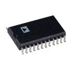
ICGOO电子元器件商城为您提供AD7537KRZ由Analog设计生产,在icgoo商城现货销售,并且可以通过原厂、代理商等渠道进行代购。 AD7537KRZ价格参考。AnalogAD7537KRZ封装/规格:数据采集 - 数模转换器, 12 位 数模转换器 2 24-SOIC。您可以下载AD7537KRZ参考资料、Datasheet数据手册功能说明书,资料中有AD7537KRZ 详细功能的应用电路图电压和使用方法及教程。
AD7537KRZ是Analog Devices Inc.生产的一款12位、双通道、8位并行接口的数模转换器(DAC),主要用于需要高精度模拟信号输出的场景。该器件具有低成本、低功耗和高性能的特点,适用于工业控制、仪器仪表、通信设备以及自动化系统等领域。其双通道输出特性使其能够同时驱动两个独立的模拟信号,适合多通道控制与信号生成应用。此外,AD7537KRZ具备较高的稳定性和抗干扰能力,广泛用于精密电源控制、传感器校准、自动测试设备(ATE)和过程控制系统等对精度要求较高的场景。
| 参数 | 数值 |
| 产品目录 | 集成电路 (IC)半导体 |
| 描述 | IC DAC 12BIT DUAL MULT 24SOIC数模转换器- DAC LC2MOS Loading Dual 12-Bit |
| 产品分类 | |
| 品牌 | Analog Devices |
| 产品手册 | |
| 产品图片 |
|
| rohs | 符合RoHS无铅 / 符合限制有害物质指令(RoHS)规范要求 |
| 产品系列 | 数据转换器IC,数模转换器- DAC,Analog Devices AD7537KRZ- |
| 数据手册 | |
| 产品型号 | AD7537KRZ |
| 产品培训模块 | http://www.digikey.cn/PTM/IndividualPTM.page?site=cn&lang=zhs&ptm=19145http://www.digikey.cn/PTM/IndividualPTM.page?site=cn&lang=zhs&ptm=18614http://www.digikey.cn/PTM/IndividualPTM.page?site=cn&lang=zhs&ptm=26125http://www.digikey.cn/PTM/IndividualPTM.page?site=cn&lang=zhs&ptm=26140http://www.digikey.cn/PTM/IndividualPTM.page?site=cn&lang=zhs&ptm=26150http://www.digikey.cn/PTM/IndividualPTM.page?site=cn&lang=zhs&ptm=26147 |
| 产品种类 | 数模转换器- DAC |
| 位数 | 12 |
| 供应商器件封装 | 24-SOIC W |
| 分辨率 | 12 bit |
| 包装 | 管件 |
| 商标 | Analog Devices |
| 安装类型 | 表面贴装 |
| 安装风格 | SMD/SMT |
| 封装 | Tube |
| 封装/外壳 | 24-SOIC(0.295",7.50mm 宽) |
| 封装/箱体 | SOIC-24 |
| 工作温度 | -40°C ~ 85°C |
| 工厂包装数量 | 31 |
| 建立时间 | 250µs |
| 接口类型 | Parallel |
| 数据接口 | 并联 |
| 最大功率耗散 | 24 mW |
| 最大工作温度 | + 125 C |
| 最小工作温度 | - 55 C |
| 标准包装 | 31 |
| 电压参考 | External |
| 电压源 | 单电源 |
| 电源电压-最大 | 16.5 V |
| 电源电压-最小 | 10.8 V |
| 积分非线性 | +/- 0.5 LSB |
| 稳定时间 | 1.5 us |
| 系列 | AD7537 |
| 结构 | R-2R |
| 转换器数 | 2 |
| 转换器数量 | 2 |
| 输出数和类型 | 2 电流,单极2 电流,双极 |
| 输出类型 | Current |
| 采样比 | 667 kSPs |
| 采样率(每秒) | 667k |


PDF Datasheet 数据手册内容提取
a LC2MOS (8+4) Loading Dual 12-Bit DAC AD7537 FEATURES FUNCTIONAL BLOCK DIAGRAM Two 12-Bit DACs in One Package DAC Ladder Resistance Matching: 0.5% Space Saving Skinny DIP and Surface Mount Packages 4-Quadrant Multiplication Low Gain Error (1 LSB max Over Temperature) Byte Loading Structure Fast Interface Timing APPLICATIONS Automatic Test Equipment Programmable Filters Audio Applications Synchro Applications Process Control GENERAL DESCRIPTION The AD7537 contains two 12-bit current output DACs on one monolithic chip. A separate reference input is provided for each DAC. The dual DAC saves valuable board space, and the monolithic construction ensures excellent thermal tracking. Both DACs are guaranteed 12-bit monotonic over the full tem- perature range. The AD7537 has a 2-byte (8 LSBs, 4 MSBs) loading structure. It is designed for right-justified data format. The control signals for register loading are A0, A1, CS,WR and UPD. Data is loaded to the input registers when CS and WR are low. To PRODUCT HIGHLIGHTS transfer this data to the DAC registers, UPD must be taken low 1. DAC to DAC Matching: withWR. Since both DACs are fabricated on the same chip, precise matching and tracking is inherent. Many applications which Added features on the AD7537 include an asynchronous CLR are not practical using two discrete DACs are now possible. line which is very useful in calibration routines. When this is Typical matching: 0.5%. taken low, all registers are cleared. The double buffering of the 2. Small Package Size: data inputs allows simultaneous update of both DACs. Also, each DAC has a separate AGND line. This increases the device The AD7537 is packaged in small 24-pin 0.3" DIPs and in versatility; for instance one DAC may be operated with 28-terminal surface mount packages. AGND biased while the other is connected in the standard 3. Wide Power Supply Tolerance: configuration. The device operates on a +12 V to +15 V V , with ±10% DD The AD7537 is manufactured using the Linear Compatible tolerance on this nominal figure. All specifications are CMOS (LC2MOS) process. It is speed compatible with most guaranteed over this range. microprocessors and accepts TTL, 74HC and 5 V CMOS logic level inputs. A REV. Information furnished by Analog Devices is believed to be accurate and reliable. However, no responsibility is assumed by Analog Devices for its use, nor for any infringements of patents or other rights of third parties which may result from its use. No license is granted by implication or One Technology Way, P.O. Box 9106, Norwood, MA 02062-9106, U.S.A. otherwise under any patent or patent rights of Analog Devices. Tel:781/329-4700 Fax:781/461-3113
AD7537–SPECIFICATIONS (V = +12 V to +15 V, (cid:2)10%, V = V = 10 V; I = AGND = 0 V, DD REFA REFB OUTA I = AGNDB = 0 V. All specifications T to T unless otherwise noted.) OUTB MIN MAX J, A K, B L, C S T U Parameter Versions Versions Versions Version Version Version Units Test Conditions/Comments ACCURACY Resolution 12 12 12 12 12 12 Bits Relative Accuracy ±1 ±1/2 ±1/2 ±1 ±1/2 ±1/2 LSB max Differential Nonlinearity ±1 ±1 ±1 ±1 ±1 ±1 LSB max All grades guaranteed mono- tonic over temperature. Gain Error ±6 ±3 ±1 ±6 ±3 ±2 LSB max Measured using R , R . FBA FBB Both DAC registers loaded with all 1s. Gain Temperature Coefficient2; ΔGain/ΔTemperature ±5 ±5 ±5 ±5 ±5 ±5 ppm/°C max Typical value is 1 ppm/°C Output Leakage Current I OUTA +25°C 10 10 10 10 10 10 nA max DAC A Register loaded T to T 150 150 150 250 250 250 nA max with all 0s MIN MAX I OUTB +25°C 10 10 10 10 10 10 nA max DAC B Register loaded T to T 150 150 150 250 250 250 nA max with all 0s MIN MAX REFERENCE INPUT Input Resistance 9 9 9 9 9 9 kΩ min Typical Input Resistance = 14 kΩ 20 20 20 20 20 20 kΩ max V , V REFA REFB Input Resistance Match ±3 ±3 ±1 ±3 ±3 ±1 % max Typically ±0.5% DIGITAL INPUTS V (lnput High Voltage) 2.4 2.4 2.4 2.4 2.4 2.4 V min IH V (Input Low Voltage) 0.8 0.8 0.8 0.8 0.8 0.8 V max IIL I (Input Current) IN +25°C ±1 ±1 ±1 ±1 ±1 ±1 μA max V = V IN DD T to T ±10 ±10 ±10 ±10 ±10 ±10 μA max MIN MAX C (lnput Capacitance)2 10 10 10 10 10 10 pF max IN POWER SUPPLY3 V 10.8/16.5 10.8/16.5 10.8/16.5 10.8/16.5 10.8/16.5 10.8/16.5 V min/V max DD I 2 2 2 2 2 2 mA max DD AC PERFORMANCE CHARACTERISTICS These characteristics are included for Design Guidance only and are not subject to test. (V = +12 V to +15 V; V = V = +10 V; I = AGNDA = 0 V, I = AGNDB = 0 V. Output Amplifiers are AD644 except where noted.) DD REFA REFB OUTA OUTB Parameter T = +25(cid:3)C T = T , T Units Test Conditions/Comments A A MIN MAX Output Current Settling Time 1.5 μs max To 0.01% of full-scale range. I load = 100 Ω, C = 13 pF. OUT EXT DAC output measured from falling edge of WR. Typical Value of Settling Time is 0.8 μs. Digital-to-Analog Glitch lmpulse 7 nV-s typ Measured with V = V = 0 V. I , I load = 100 Ω, REFA REFB OUTA OUTB C = 13 pF. DAC registers alternately loaded with all 0s and all 1s. EXT AC Feedthrough4 V to I –70 –65 dB max V , V = 20 V p-p 10 kHz sine wave. REFA OUTA REFA REFB V to I –70 –65 dB max DAC registers loaded with all 0s. REFB OUTB Power Supply Rejection ΔGain/ΔV ±0.01 ±0.02 % per % max ΔV = V max – V min DD DD DD DD Output Capacitance C 70 70 pF max DAC A, DAC B loaded with all 0s OUTA C 70 70 pF max OUTB C 140 140 pF max DAC A, DAC B loaded with all 1s OUTA C 140 140 pF max OUTB Channel-to-Channel Isolation V to I –84 dB typ V = 20 V p-p 10 kHz sine wave, V = 0 V. REFA OUTB REFA REFB Both DACs loaded with all 1s. V to I –84 dB typ V = 20 V p-p 10 kHz sine wave, V = 0 V. REFB OUTA REFB REFA Both DACs loaded with all 1s. Digital Crosstalk 7 nV-s typ Measured for a Code Transition of all 0s to all 1s. I , I load = 100 Ω, C = 13 pF. OUTA OUTB EXT Output Noise Voltage Density 25 nV/√Hz typ Measured between R and I or R and I FBA OUTA FBB OUTB. (10 Hz–100 kHz) Frequency of measurement is 10 Hz–100 kHz. Total Harmonic Distortion –82 dB typ V = 6 V rms, 1 kHz. Both DACs loaded with all 1s. IN NOTES 1Temperature range as follows: J, K, L Versions: –40°C to +85°C; A, B, C Versions: –40°C to +85°C; 2Sample tested at +25°C to ensure compliance. S, T, U Versions: –55°C to +125°C 3Functional at VDD = 5 V, with degraded specifications. 4Pin 12 (DGND) on ceramic DIPs is connected to lid. Specifications subject to change without notice. A –2– REV.
AD7537 TIMING CHARACTERISTICS (V = +10.8 V to +16.5 V, V = V = +10 V; I = AGNDA = 0 V, I = AGNDB = 0 V.) DD REFA REFB OUTA OUTB Limit at Limit at Limit at T = –40(cid:3)C T = +55(cid:3)C A A Parameter T = +25(cid:3)C to +85(cid:3)C to +125(cid:3)C Units Test Conditions/Comments A t 15 15 30 ns min Address Valid to Write Setup Time 1 t 15 15 25 ns min Address Valid to Write Hold Time 2 t 60 80 80 ns min Data Setup Time 3 t 25 25 25 ns min Data Hold Time 4 t 0 0 0 ns min Chip Select or Update to Write Setup Time 5 t 0 0 0 ns min Chip Select or Update to Write Hold Time 6 t 80 80 100 ns min Write Pulse Width 7 t 80 80 100 ns min Clear Pulse Width 8 Specifications subject to change without notice. ABSOLUTE MAXIMUM RATINGS* Operating Temperature Range (T = +25°C unless otherwise stated) Commercial Plastic (J, K, L Versions) . . . . –40°C to +85°C A V to DGND . . . . . . . . . . . . . . . . . . . . . . . . . .–0.3 V, +17 V Industrial Hermetic (A, B, C Versions) . . .–40°C to +85°C VDD , V to AGNDA, AGNDB . . . . . . . . . . . . . . . .±25 V Extended Hermetic (S, T, U Versions) . . –55°C to +125°C VREFA, VREFB to AGNDA, AGNDB . . . . . . . . . . . . . . . .±25 V Storage Temperature . . . . . . . . . . . . . . . . –65°C to +150°C DRigFiBtAal InRpFuBBt Voltage to DGND . . . . . . . –0.3 V, V +0.3 V Lead Temperature (Soldering, 10 sec) . . . . . . . . . . . . +300°C DD IOUTA, IOUTB to DGND . . . . . . . . . . . . . . –0.3 V, VDD +0.3 V *Stresses above those listed under “Absolute Maximum Ratings” may cause AGNDA, AGNDB to DGND . . . . . . . . . –0.3 V, V +0.3 V permanent damage to the device. This is a stress rating only and functional DD Power Dissipation (Any Package) operation of the device at these or any other conditions above those indicated in To +75°C . . . . . . . . . . . . . . . . . . . . . . . . . . . . . . . . 450 mW the operational sections of this specification is not implied. Exposure to absolute maximum rating conditions for extended periods may affect device reliability. Derates Above +75°C . . . . . . . . . . . . . . . . . . . . . 6 mW/°C CAUTION ESD (electrostatic discharge) sensitive device. Electrostatic charges as high as 4000 V readily WARNING! accumulate on the human body and test equipment and can discharge without detection. Although the AD7537 features proprietary ESD protection circuitry, permanent damage may occur on devices subjected to high energy electrostatic discharges. Therefore, proper ESD precautions are recommended to avoid performance degradation or loss of functionality. ESD SENSITIVE DEVICE Figure 1.Timing Diagram A REV. –3–
AD7537 PIN FUNCTION DESCRIPTION (PDIP) current flowing in each ladder leg is constant, irrespective of switch state. The feedback resistor R is used with an op amp FBA PIN MNEMONIC DESCRIPTION (see Figures 4 and 5) to convert the current flowing in I to OUTA a voltage output. 1 AGNDA Analog Ground for DAC A. 2 I Current output terminal of DAC A. OUTA 3 R Feedback resistor for DAC A. FBA 4 V Reference input to DAC A. REFA 5 CS Chip Select Input Active low. 6–14 DB0–DB7 Eight data inputs, DB0–DB7. 12 DGND Digital Ground. 15 A0 Address Line 0. 16 A1 Address Line 1. 17 CLR Clear Input. Active low. Clears all registers. Figure 2.Simplified Circuit Diagram for DAC A 18 WR Write Input. Active low. 19 UPD Updates DAC Registers from inputs EQUIVALENT CIRCUIT ANALYSIS registers. Figure 3 shows the equivalent circuit for one of the D/A con- 20 V Power supply input. Nominally +12 V DD verters (DAC A) in the AD7537. A similar equivalent circuit to +15 V, with ±10% tolerance. can be drawn for DAC B. 21 V Reference input to DAC B. REFB 22 RFBB Feedback resistor for DAC B. COUT is the output capacitance due to the N-channel switches 23 I Current output terminal of DAC B. and varies from about 50 pF to 150 pF with digital input code. OUTB 24 AGNDB Analog Ground for DAC B. The current source ILKG is composed of surface and junction leakages and approximately doubles every 10°C. R is the 0 equivalent output resistance of the device which varies with PIN CONFIGURATIONS input code. PDIP and SOIC DIGITAL CIRCUIT INFORMATION The digital inputs are designed to be both TTL and 5 V CMOS compatible. All logic inputs are static protected MOS gates with typical input currents of less than 1 nA. Table I. AD7537 Truth Table CLR UPD CS WR A1 A0 FUNCTION 1 1 1 X X X No Data Transfer 1 1 X 1 X X No Data Transfer 0 X X X X X All Registers Cleared 1 1 0 0 0 0 DAC A LS Input Register Loaded with DB7–DB0 (LSB) PLCC 1 1 0 0 0 1 DAC A MS Input Register Loaded with DB3 (MSB)–DB0 1 1 0 0 1 0 DAC B LS Input Register Loaded with DB7–DB0 (LSB) 1 1 0 0 1 1 DAC B MS Input Register Loaded with DB3 (MSB)–DB0 1 0 1 0 X X DAC A, DAC B Registers Updated Simultaneously from Input Registers 1 0 0 0 X X DAC A, DAC B Registers are Transparent NOTES: X = Don’t care CIRCUIT INFORMATION – D/A SECTION The AD7537 contains two identical 12-bit multiplying D/A converters. Each DAC consists of a highly stable R-2R ladder and 12 N-channel current steering switches. Figure 2 shows a simplified D/A circuit for DAC A. In the R-2R ladder, binary weighted currents are steered between I and AGNDA. The Figure 3.Equivalent Analog Circuit for DAC A OUTA A –4– REV.
Applications–AD7537 UNIPOLAR BINARY OPERATION BIPOLAR OPERATION (2-QUADRANT MULTIPLICATION) (4-QUADRANT MULTIPLICATION) Figure 4 shows the circuit diagram for unipolar binary opera- The recommended circuit diagram for bipolar operation is tion. With an ac input, the circuit performs 2-quadrant multipli- shown in Figure 5. Offset binary coding is used. cation. The code table for Figure 4 is given in Table II. With the appropriate DAC register loaded to 1000 0000 0000, Operational amplifiers A1 and A2 can be in a single package adjust R1 (R3) so that V (V ) = 0 V. Alternatively, R1, OUTA OUTB (AD644, AD712) or separate packages (AD544, AD711, R2 (R3, R4) may be omitted and the ratios of R6, R7 (R9, 10) AD OP27). Capacitors C1 and C2 provide phase compensation varied for V (V ) = 0 V. Full-scale trimming can be ac- OUTA OUTB to help prevent overshoot and ringing when high-speed op amps complished by adjusting the amplitude of V or by varying the IN are used. value of R5 (R8). For zero offset adjustment, the appropriate DAC register is If R1, R2 (R3, R4) are not used, then resistors R5, R6, R7 (R8, loaded with all 0s and amplifier offset adjusted so that V or R9, R10) should be ratio matched to 0.01% to ensure gain error OUTA V is 0 V. Full-scale trimming is accomplished by loading performance to the data sheet specification. When operating OUTB the DAC register with all 1s and adjusting R1 (R3) so that over a wide temperature range, it is important that the resistors V (V ) = –V (4095/4096). For high temperature op- be of the same type so that their temperature coefficients match. OUTA OUTB IN eration, resistors and potentiometers should have a low Tem- The code table for Figure 5 is given in Table III. perature Coefficient. In many applications, because of the excellent Gain T.C. and Gain Error specifications of the AD7537, Gain Error trimming is not necessary. In fixed refer- ence applications, full scale can also be adjusted by omitting R1, R2, R3, R4 and trimming the reference voltage magnitude. Figure 5.Bipolar Operation (Offset Binary Coding) Table III. Bipolar Code Table for Offset Binary Circuit of Figure 5 Binary Number in DAC Register Analog Output, Figure 4.AD7537 Unipolar Binary Operation MSB LSB V or V OUTA OUTB Table II. Unipolar Binary Code Table for ⎛2047⎞ Circuit of Figure 4 1111 1111 1111 +VIN⎝⎜2048⎠⎟ Binary Number in DAC Register Analog Output, ⎛ 1 ⎞ MSB LSB VOUTA or VOUTB 1000 0000 0001 +VIN⎝⎜2048⎠⎟ 1000 0000 0000 0 V ⎛4095⎞ 1111 1111 1111 −VIN⎝⎜4096⎠⎟ 0111 1111 1111 −VIN⎛⎝⎜20148⎞⎠⎟ ⎛2048⎞ 1000 0000 0000 −VIN⎝⎜4096⎠⎟=−12VIN 0000 0000 0000 −VIN⎛⎝⎜22004488⎞⎠⎟=−VIN ⎛ 1 ⎞ 0000 0000 0001 −VIN⎝⎜4096⎠⎟ 0000 0000 0000 0 V A REV. –5–
AD7537 SEPARATE AGND PINS the AD7537 controls the programmable integrators. The fre- The DACs in the AD7537 have separate AGND lines taken to quency of oscillation is given by: pins AGNDA and AGNDB on the package. This increases the applications versatility of the part. Figure 6 is an example of f = 1 R6× 1 this. DAC A is connected in standard fashion as a program- 2π R5 C1×C2×REQ1×REQ2 mable attenuator. AGNDA is at ground potential. DAC B is op- where R and R are the equivalent resistances of the EQ1 EQ2 erating with AGND B biased to +5 V by the AD584. This gives DACs. The same digital code is loaded into both DACs. an output range of +5 V to +10 V. If C1 = C2 and R5 = R6, the expression reduces to 1 1 1 f = × 2π C R ×R EQ1 EQ2 2n×R Since R = LAD , (R = DAC ladder resistance). EQ N LAD 1 1 (N/2n)2 f = × 2π C R ×R LAD1 LAD2 1 D 1 ⎛N⎞ = × D=⎜ ⎟ 2π C R ×R ⎝2n⎠ LAD1 LAD2 1 D = × 2π C×R LAD m where m is the DAC ladder resistance mismatch ratio, typically 1.005. With the values shown in Figure 7, the output frequency varies Figure 6.AD7537 DACs Used in Different Modes from 0 Hz to 1.38 kHz. The amplitude of the output signal at the A3 output is 10 V peak-to-peak and is constant over the PROGRAMMABLE OSCILLATOR entire frequency span. Figure 7 shows a conventional state variable oscillator in which Figure 7.Programmable State Variable Oscillator A –6– REV.
AD7537 APPLICATION HINTS other for the MC68008. Figure 11 shows how an AD7537 sys- Output Offset: CMOS D/A converters in circuits such as Fig- tem can be easily expanded by tying all the UPD lines together ures 4 and 5 exhibit a code dependent output resistance which and using a single decoder output to control these. This ex- in turn can cause a code dependent error voltage at the output panded system is shown using a Z80 microprocessor but it is of the amplifier. The maximum amplitude of this error, which just as easily configured using any other 8-bit microprocessor adds to the D/A converter nonlinearity, depends on V , where system. Note how the system shown in Figure 11 produces 4 OS V is the amplifier input offset voltage. To maintain specified analog outputs with a minimum amount of hardware. OS operation, it is recommended that V be no greater than OS (25(cid:2) 10–6) (V ) over the temperature range of operation. REF Suitable op amps are the AD711C and its dual version, the AD712C. These op amps have a wide bandwidth and high slew rate and are recommended for wide bandwidth ac applications. AD711/AD712 settling time to 0.01% is typically 3 μs. Temperature Coefficients: The gain temperature coefficient of the AD7537 has a maximum value of 5 ppm/°C and typical value of 1 ppm/°C. This corresponds to worst case gain shifts of 2 LSBs and 0.4 LSBs respectively over a 100°C temperature range. When trim resistors R1 (R3) and R2 (R4) are used to ad- just full scale range as in Figure 4, the temperature coefficient of R1 (R3) and R2 (R4) should also be taken into account. For further information see “Gain Error and Gain Temperature Co- efficient of CMOS Multiplying DACs”, Application Note, Pub- lication Number E630c-5-3/86 available from Analog Devices. Figure 9.AD7537–MC6809 Interface High Frequency Considerations: AD7537 output capaci- tance works in conjunction with the amplifier feedback resis- tance to add a pole to the open loop response. This can cause ringing or oscillation. Stability can be restored by adding a phase compensation capacitor in parallel with the feedback re- sistor. This is shown as C1 and C2 in Figures 4 and 5. Feedthrough: The dynamic performance of the AD7537 de- pends upon the gain and phase stability of the output amplifier, together with the optimum choice of PC board layout and de- coupling components. A suggested printed circuit layout for Figure 4 is shown in Figure 8 which minimizes feedthrough from V , V to the output in multiplying applications. REFA REFB Figure 10.AD7537–MC68008 Interface Figure 8.Suggested Layout for AD7537 MICROPROCESSOR INTERFACING The byte loading structure of the AD7537 makes it very easy to Figure 11.Expanded AD7537 System interface the device to any 8-bit microprocessor system. Figures 9 and 10 show two interfaces: one for the MC6809 and the A REV. –7–
AD7537 OUTLINE DIMENSIONS 1.280 (32.51) 1.250 (31.75) 1.230 (31.24) 24 13 0.280 (7.11) 0.250 (6.35) 1 12 0.240 (6.10) 0.325 (8.26) 0.310 (7.87) 0.100 (2.54) 0.300 (7.62) BSC 0.060 (1.52) 0.195 (4.95) 0.210 (5.33) MAX 0.130 (3.30) MAX 0.115 (2.92) 0.015 0.150 (3.81) (0.38) 0.015 (0.38) 0.130 (3.30) MIN GAUGE 0.115 (2.92) SEATING PLANE 00..001140 ((00..3265)) PLANE 0.022 (0.56) 0.008 (0.20) 0.005 (0.13) 0.430 (10.92) 0.018 (0.46) MIN MAX 0.014 (0.36) 0.070 (1.78) 0.060 (1.52) 0.045 (1.14) COMPLIANTTO JEDEC STANDARDS MS-001 CONTROLLING DIMENSIONSARE IN INCHES; MILLIMETER DIMENSIONS (RCINEOFRPEANRREEREN NLCTEEHA EODSNSEL MSY)AAAYNR BDEE AR CROOEU NNNFODIGETUDAR-POEPFDRFOA INSPC RWHIAH ETOEQL UFEIO VORAR LU EHSNAETL ISFN FLDOEEARSDIGSN.. 071006-A Figure 12. 24-Lead Plastic Dual In-Line Package [PDIP] Narrow Body (N-24-1) Dimensions shown in inches and (millimeters) 0.180 (4.57) 0.048 (1.22) 0.165 (4.19) 0.042 (1.07) 0.056 (1.42) 0.020 (0.51) 0.042 (1.07) MIN 4 26 0.048 (1.22) 5 PIN 1 25 0.021 (0.53) 0.042 (1.07) IDENTIFIER 0.013 (0.33) BOTTOM TOP VIEW 0.050 0.430 (10.92) VIEW (PINS DOWN) (1.27) 0.390 (9.91) (PINS UP) BSC 0.032 (0.81) 0.026 (0.66) 11 19 12 18 0.045 (1.14) 00..445560 ((1111..548320))SQ 0.120 (3.04) 0.025 (0.64) R 0.090 (2.29) 0.495 (12.57) SQ 0.485 (12.32) COMPLIANT TO JEDEC STANDARDS MO-047-AB C(RINOE FNPETARRREOENLNCLTEIHN EOGSN DELISYM) AEANNRSDEI OARRNOESU NNAODREETD IAN-PO IPFNRFCO HINPECRSHI;A METQIEL ULFIIOVMAREL TUEESNRET DSINI MF DOEENRSSIGIONN.S 042508-A Figure 16. 28-Lead Plastic Leaded Chip Carrier [PLCC] (P-28) Dimensions shown in inches and (millimeters) –8– REV. A
AD7537 15.60(0.6142) 15.20(0.5984) 24 13 7.60(0.2992) 7.40(0.2913) 1 10.65(0.4193) 12 10.00(0.3937) 0.75(0.0295) 45° 2.65(0.1043) 0.25(0.0098) 0.30(0.0118) 2.35(0.0925) 8° 0.10(0.0039) 0° COPLANARITY 0.10 1.27B(0S.C0500) 00..5311((00..00210212)) SPLEAATNIENG 00..3230((00..00103709)) 10..2470((00..00510507)) COMPLIANTTOJEDECSTANDARDSMS-013-AD C(RINOEFNPEATRRREOENNLCLTEIHNEOGSNDELISYM)AEANNRDSEIAORRNOESUNANORDETEDAIN-POMPFRIFLOLMPIMIRLELIATIMTEEERTFSEO;RIRNECUQHSUEDIVIINMAELDENENSSTIIOGSNNFS.OR 12-09-2010-A Figure 17. 24-Lead Standard Small Outline Package [SOIC-W] Wide Body (RW-24) Dimensions shown in inches and (millimeters) ORDERING GUIDE Model1, 2, 3 Temperature Range Relative Accuracy Gain Error Package Description Package Option AD7537JN –40°C to +85°C ±1 LSB ±6 LSB 24-Lead PDIP N-24-1 AD7537JNZ –40°C to +85°C ±1 LSB ±6 LSB 24-Lead PDIP N-24-1 AD7537KN –40°C to +85°C ±1/2 LSB ±3 LSB 24-Lead PDIP N-24-1 AD7537KNZ –40°C to +85°C ±1/2 LSB ±3 LSB 24-Lead PDIP N-24-1 AD7537LNZ –40°C to +85°C ±1/2 LSB ±1 LSB 24-Lead PDIP N-24-1 AD7537JP –40°C to +85°C ±1 LSB ±6 LSB 28-Lead PLCC P-28 AD7537JP-REEL –40°C to +85°C ±1 LSB ±6 LSB 28-Lead PLCC P-28 AD7537JPZ –40°C to +85°C ±1 LSB ±6 LSB 28-Lead PLCC P-28 AD7537JPZ-REEL –40°C to +85°C ±1 LSB ±6 LSB 28-Lead PLCC P-28 AD7537KP –40°C to +85°C ±1/2 LSB ±3 LSB 28-Lead PLCC P-28 AD7537KPZ –40°C to +85°C ±1/2 LSB ±3 LSB 28-Lead PLCC P-28 AD7537KPZ-REEL –40°C to +85°C ±1/2 LSB ±3 LSB 28-Lead PLCC P-28 AD7537LP-REEL –40°C to +85°C ±1/2 LSB ±1 LSB 28-Lead PLCC P-28 AD7537LPZ –40°C to +85°C ±1/2 LSB ±1 LSB 28-Lead PLCC P-28 AD7537LPZ-REEL –40°C to +85°C ±1/2 LSB ±1 LSB 28-Lead PLCC P-28 AD7537JR –40°C to +85°C ±1 LSB ±6 LSB 24-Lead SOIC_W RW-24 AD7537JR-REEL –40°C to +85°C ±1 LSB ±6 LSB 24-Lead SOIC_W RW-24 AD7537JRZ –40°C to +85°C ±1 LSB ±6 LSB 24-Lead SOIC_W RW-24 AD7537JRZ-REEL –40°C to +85°C ±1 LSB ±6 LSB 24-Lead SOIC_W RW-24 AD7537KRZ –40°C to +85°C ±1/2 LSB ±3 LSB 24-Lead SOIC_W RW-24 AD7537KR-REEL –40°C to +85°C ±1/2 LSB ±3 LSB 24-Lead SOIC_W RW-24 AD7537BR –40°C to +85°C ±1/2 LSB ±3 LSB 24-Lead SOIC_W RW-24 AD7537BR-REEL –40°C to +85°C ±1/2 LSB ±3 LSB 24-Lead SOIC_W RW-24 AD7537BRZ –40°C to +85°C ±1/2 LSB ±3 LSB 24-Lead SOIC_W RW-24 1 Z = RoHS Compliant Part. 2 Analog Devices reserves the right to ship side-brazed CERDIP packages (D-24-1) in lieu of CERDIP packages (Q-24-1). 3 To order MIL-STD-883, Class B processed parts, add/883B to part number. Contact your local sales office for military data sheet. REV. A –9–
AD7537 REVISION HISTORY 6/12—Rev. 0 to Rev. A Added SOIC Package ......................................................... Universal Removed LCCC Pin Configuration ................................................ 4 Updated Outline Dimensions .......................................................... 8 Changes to Ordering Guide ............................................................. 9 10/87—Revision 0: Initial Version ©1987–2012 Analog Devices, Inc. All rights reserved. Trademarks and registered trademarks are the property of their respective owners. D01138-0-6/12(A) –10– REV. A
Mouser Electronics Authorized Distributor Click to View Pricing, Inventory, Delivery & Lifecycle Information: A nalog Devices Inc.: AD7537LNZ AD7537KP AD7537KPZ AD7537JP AD7537JR AD7537LPZ AD7537JPZ 5962-8776303LX AD7537UQ AD7537JRZ AD7537CQ AD7537KR-REEL AD7537JN AD7537KNZ AD7537KN AD7537JRZ-REEL AD7537BQ AD7537JR-REEL AD7537AQ AD7537JNZ AD7537KRZ AD7537JPZ-REEL