 Datasheet下载
- 型号: AC05000001501JAC00
- 制造商: Vishay
- 库位|库存: xxxx|xxxx
- 要求:
| 数量阶梯 | 香港交货 | 国内含税 |
| +xxxx | $xxxx | ¥xxxx |
查看当月历史价格
查看今年历史价格
AC05000001501JAC00产品简介:
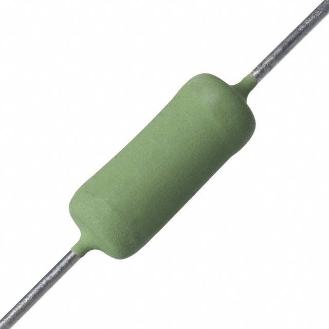
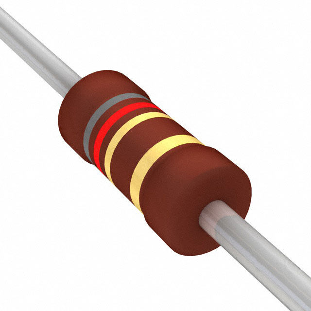
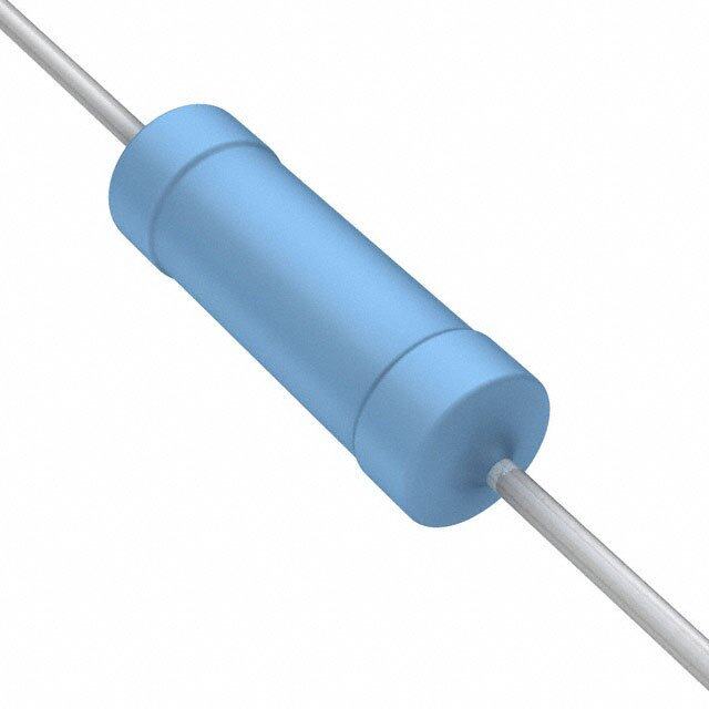
ICGOO电子元器件商城为您提供AC05000001501JAC00由Vishay设计生产,在icgoo商城现货销售,并且可以通过原厂、代理商等渠道进行代购。 AC05000001501JAC00价格参考。VishayAC05000001501JAC00封装/规格:通孔电阻器, 1.5 kOhms ±5% 5W 轴向 通孔电阻器 阻燃涂层,脉冲耐受,安全 绕线。您可以下载AC05000001501JAC00参考资料、Datasheet数据手册功能说明书,资料中有AC05000001501JAC00 详细功能的应用电路图电压和使用方法及教程。
Vishay BC Components的通孔电阻器型号AC05000001501JAC00属于功率绕线电阻器系列,其应用场景广泛,适用于需要高功率、高稳定性和高耐久性的电路设计。以下是该型号的主要应用场景:

 1. 电源管理
   - 用于开关电源(SMPS)、线性电源和直流-直流转换器中的限流或分压。
   - 在启动阶段作为预充电电阻,限制浪涌电流。

 2. 工业控制
   - 在电机驱动和伺服控制系统中用作制动电阻或负载平衡电阻。
   - 用于变频器和逆变器中的能量耗散元件。

 3. 测量与测试设备
   - 用作精密测量仪器中的标准电阻或校准电阻。
   - 在电流检测电路中提供精确的电压降。

 4. 通信设备
   - 在基站和通信模块中用作功率匹配或信号衰减电阻。
   - 提供过载保护功能,防止电路因过流而损坏。

 5. 汽车电子
   - 应用于汽车启动系统、发电机调节器和车载充电器中。
   - 用于电动汽车(EV)或混合动力汽车(HEV)的能量回收系统。

 6. 家用电器
   - 在洗衣机、空调和冰箱等家电中用作启动电阻或加热元件。
   - 用于过热保护电路或温度补偿电路。

 7. 医疗设备
   - 在医疗成像设备(如X射线机、CT扫描仪)中用作功率缓冲或负载电阻。
   - 提供稳定的阻值以确保设备精度。

 8. 航空航天与国防
   - 用于高可靠性需求的军工设备中,如雷达系统和卫星通信。
   - 能够承受极端环境条件,保证长期稳定性。

 特性优势:
- 高功率处理能力:适合大电流应用。
- 优异的耐热性能:能够在高温环境下稳定工作。
- 低噪音特性:减少对敏感电路的影响。
- 高精度和稳定性:满足精密电路的需求。

综上所述,AC05000001501JAC00电阻器因其卓越的性能,适用于各种工业级和消费级电子设备,特别是在需要高功率、高可靠性和高稳定性的场景中表现出色。
| 参数 | 数值 |
| 产品目录 | |
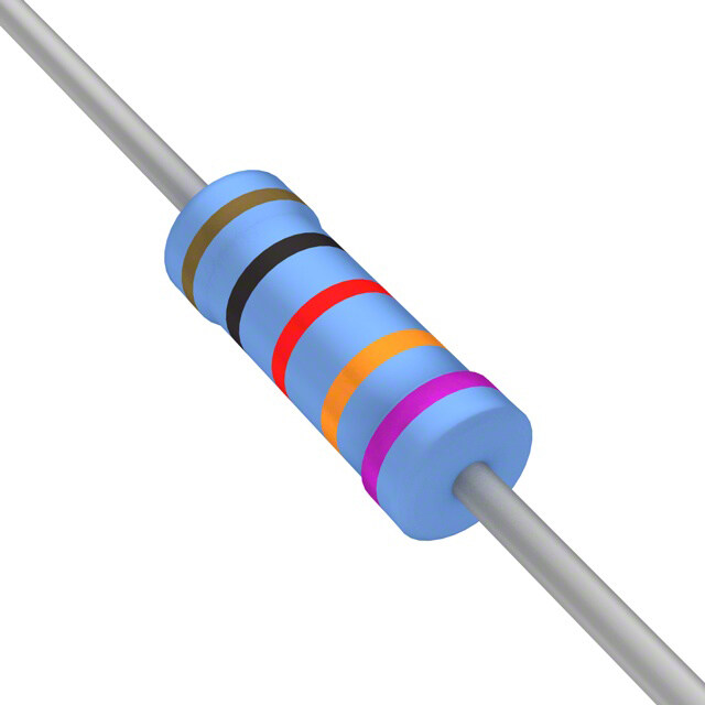
| 描述 | RES 1.5K OHM 5W 5% AXIAL线绕电阻器 - 透孔 5watts 1.5Kohms 5% |
| 产品分类 | |
| 品牌 | Vishay BC ComponentsVishay / Draloric |
| 产品手册 | http://www.vishay.com/doc?28730 |
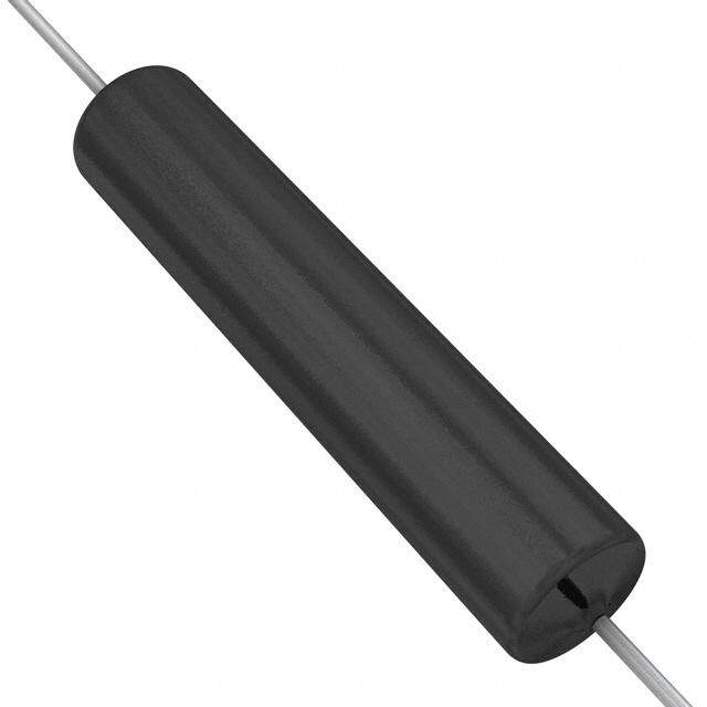
| 产品图片 |
|
| rohs | 符合RoHS无铅 / 符合限制有害物质指令(RoHS)规范要求 |
| 产品系列 | 线绕电阻器,线绕电阻器 - 透孔,Vishay / Draloric AC05000001501JAC00AC |
| 数据手册 | |
| 产品型号 | AC05000001501JAC00AC05000001501JAC00 |
| 产品 | Power Resistors Wirewound Cement Filled Ceramic |
| 产品目录绘图 |
|
| 产品种类 | 线绕电阻器 - 透孔 |
| 供应商器件封装 | 轴向 |
| 其它名称 | 2322 329 05152 |
| 功率(W) | 5W |
| 功率额定值 | 5 W |
| 包装 | 带盒(TB) |
| 商标 | Vishay / Draloric |
| 外壳直径 | 7.5 mm |
| 外壳长度 | 18 mm |
| 大小/尺寸 | 0.295" 直径 x 0.709" 长(7.50mm x 18.00mm) |
| 容差 | ±5%5 % |
| 封装 | Ammo Pack |
| 封装/外壳 | 轴向 |
| 工作温度范围 | 0 C to + 275 C |
| 工厂包装数量 | 500 |
| 引线直径 | 0.8 mm |
| 成分 | 绕线 |
| 标准包装 | 500 |
| 温度系数 | 100 PPM / K, 180 PPM / K100/ +180ppm/°C |
| 特性 | 耐燃 |
| 电阻 | 1.5 kOhms |
| 电阻(Ω) | 1.5k |
| 端子数 | 2 |
| 端接类型 | Axial |
| 类型 | Cemented Wirewound Resistor |
| 系列 | AC05 |
| 高度 | - |


- 商务部:美国ITC正式对集成电路等产品启动337调查
- 曝三星4nm工艺存在良率问题 高通将骁龙8 Gen1或转产台积电
- 太阳诱电将投资9.5亿元在常州建新厂生产MLCC 预计2023年完工
- 英特尔发布欧洲新工厂建设计划 深化IDM 2.0 战略
- 台积电先进制程称霸业界 有大客户加持明年业绩稳了
- 达到5530亿美元!SIA预计今年全球半导体销售额将创下新高
- 英特尔拟将自动驾驶子公司Mobileye上市 估值或超500亿美元
- 三星加码芯片和SET,合并消费电子和移动部门,撤换高东真等 CEO
- 三星电子宣布重大人事变动 还合并消费电子和移动部门
- 海关总署:前11个月进口集成电路产品价值2.52万亿元 增长14.8%

PDF Datasheet 数据手册内容提取
AC, AC-AT www.vishay.com Vishay Draloric Cemented Leaded Wirewound Resistors FEATURES • AEC-Q200 qualified AC-AT series • High power dissipation in small design • Non-flammable coating conforming to UL 94 V-0 • Excellent pulse load capability • Non-inductive (NI) version available • WSZ-form lead bending available for SMD mounting DESIGN SUPPORT TOOLS click logo to get started • Material categorization: for definitions of compliance please see www.vishay.com/doc?99912 Models Available APPLICATIONS The AC series is the perfect choice for general purpose • Automotive electronics power applications. The AEC-Q200 qualified AC-AT series is best suited for automotive applications. The robust silicon • Industrial electronics cement coating can handle challenging ambient and • Power supplies operating conditions. Typical applications include but are not limited to energy meters, power supplies and • White goods automotive electronics. For a given application, • Pre-charged applications requirements of ohmic value, rated power, peak voltage, pulse shape, pulse duration, lead bending, and environmental conditions may be submitted to recommend the most suitable product. Various lead forms are available such as RT (radial taped), WSZ (Z-form), DK (double kink), EK (single kink) with defined mounting pitch. STANDARD ELECTRICAL SPECIFICATIONS RESISTANCE RESISTANCE RESISTANCE RATED RATED LIMITING RANGE (1) RANGE (1) RANGE (1) RESISTANCE TYPE DISSIPATION DISSIPATION VOLTAGE TCR = TCR = TCR = TOLERANCE P P U -10 ppm/K to +100 ppm/K to ± 100 ppm/K 40 70 max. -80 ppm/K +180 ppm/K AC01 1 W 0.9 W P x R 0.10 to 33 36 to 2.4 k - ± 5 % AC01-AT 1 W 0.9 W P x R 0.39 to 33 36 to 2.4 k - ± 5 % AC03 (2) 3 W 2.5 W P x R 0.10 to 390 430 to 3.3 k 3.6 k to 5.1 k ± 5 % AC03-AT 3 W 2.5 W P x R 0.27 to 390 430 to 3.3 k - ± 5 % AC04 4 W 3.5 W P x R 0.10 to 620 680 to 6.8 k - ± 5 % AC04-AT 4 W 3.5 W P x R 0.22 to 620 680 to 6.8 k - ± 5 % AC05 5 W 4.7 W P x R 0.10 to 910 1.0 k to 10 k - ± 5 % AC05-AT 5 W 4.7 W P x R 0.62 to 910 1.0 k to 10 k - ± 5 % AC07 7 W 5.8 W P x R 0.10 to 820 910 to 15 k - ± 5 % AC07-AT 7 W 5.8 W P x R 1.0 to 820 910 to 15 k - ± 5 % AC10 10 W 8.4 W P x R 0.22 to 560 620 to 27 k - ± 5 % AC10-AT 10 W 8.4 W P x R 2.0 to 560 620 to 27 k - ± 5 % Notes • The operating temperature range for these resistors is from -55 °C up to 250 °C (1) Resistance value to be selected for ± 5 % from E24 (2) AC03 WSZ: P = 1.8 W; P = 1.5 W 40 70 °C Revision: 11-Jul-2018 1 Document Number: 28730 For technical questions, contact: ww1resistors@vishay.com THIS DOCUMENT IS SUBJECT TO CHANGE WITHOUT NOTICE. THE PRODUCTS DESCRIBED HEREIN AND THIS DOCUMENT ARE SUBJECT TO SPECIFIC DISCLAIMERS, SET FORTH AT www.vishay.com/doc?91000
AC, AC-AT www.vishay.com Vishay Draloric PART NUMBER AND PRODUCT DESCRIPTION Part Number: AC03000001509JAC00 AC03AT0001509JAC00 A C 0 3 0 0 0 0 0 1 5 0 9 J A C 0 0 A C 0 3 A T 0 0 0 1 5 0 9 J A C 0 0 TCR / TOLERANCE PACKAGING MODEL VARIANT VALUE SPECIAL MATERIAL CODE CODE AC01000 = AC01 0 = neutral 0 = standard 3 digit value J = ± 5.0 % (see 00 = standard AC03000 = AC03 1 = RT 1 digit Packaging 2 digit code = AC04000 = AC04 2 = SWI multiplier table) customized version (1) AC05000 = AC05 3 = DK SP 20 mm MULTIPLIER AC07000 = AC07 4 = DK LP 33 mm 7 = *10-3 AC10000 = AC10 5 = DK LP 17.8 mm 8 = *10-2 6 = NI Non inductive 9 = *10-1 AC01AT0 = AC01-AT 7 = DK LP 25.4 mm 0 = *100 AC03AT0 = AC03-AT 8 = DK SP 25.4 mm 1 = *101 AC04AT0 = AC04-AT 9 = WSZ 6720 2 = *102 AC05AT0 = AC05-AT Z = Value overflow AC07AT0 = AC07-AT A = EK 22.5 mm AC10AT0 = AC10-AT B = EK 17.8 mm C = EK 25.4 mm D = Cu wire 0.8 mm E = EK 33 mm G = DK SP 33 mm H = EK 20 mm I = DK SP 17.8 mm Product Description: AC03 15R 5 % AC AC03AT 15R 5 % AC AC03 15R 5 % AC AC03-AT 15R 5 % AC TYPE RESISTANCE TOLERANCE PACKAGING AC01 AC01-AT R10 = 0.1 5 % AC LB AC03 AC03-AT 75R = 75 A1 LC AC04 AC04-AT 27K = 27 k AB LK AC05 AC05-AT AE BM AC07 AC07-AT AC10 AC10-AT Note (1) For special windings or the non-inductive versions, please contact: ww1resistors@vishay.com Revision: 11-Jul-2018 2 Document Number: 28730 For technical questions, contact: ww1resistors@vishay.com THIS DOCUMENT IS SUBJECT TO CHANGE WITHOUT NOTICE. THE PRODUCTS DESCRIBED HEREIN AND THIS DOCUMENT ARE SUBJECT TO SPECIFIC DISCLAIMERS, SET FORTH AT www.vishay.com/doc?91000
AC, AC-AT www.vishay.com Vishay Draloric PACKAGING TYPE / SIZE CODE DESCRIPTION QUANTITY PACKAGING STYLE WIDTH PITCH DIMENSIONS AC01 Taped acc. to IEC 60286-1 A1 A1 1000 63 mm 10 mm 260 mm x 85 mm x 70 mm AC01-AT fan-folded in a box AC01 DK/EK LC LC 500 Bulk packaging - - 260 mm x 80 mm x 55 mm Taped acc. to IEC 60286-2 AC01 RT AE RE 2500 - 12.7 mm 200 mm x 46 mm x 334 mm fan-folded in a box AC03 Taped acc. to IEC 60286-1 AC AC 500 63 mm 10 mm 260 mm x 85 mm x 58 mm AC03-AT fan-folded in a box AC03 DK/EK LC LC 500 Bulk packaging - - 224 mm x 82 mm x 54 mm Taped acc. to IEC 60286-2 AC03 RT AQ AQ 1800 - 12.7 mm 200 mm x 46 mm x 334 mm fan-folded in a box AC03 WSZ Blister taped acc. to BM BM 1250 - 8 mm 350 mm x 350 mm x 55 mm AC03-AT WSZ IEC 60286-3 in a box AC04 (1) Taped acc. to IEC 60286-1 260 mm x 85 mm x 70 mm AC AC 500 63 mm 10 mm AC04-AT (1) fan-folded in a box 260 mm x 85 mm x 58 mm AC04 DK/EK LC LC 500 Bulk packaging - 25.4 mm 224 mm x 82 mm x 54 mm AC05 Taped acc. to IEC 60286-1 AC AC 500 63 mm 5 mm 270 mm x 86 mm x 118 mm AC05-AT fan-folded in a box AC05 DK/EK LC LC 500 Bulk packaging - - 224 mm x 82 mm x 54 mm AC07 Taped acc. to IEC 60286-1 AC AC 500 73 mm 10 mm 26 mm x 90 mm x 118 mm AC07-AT fan-folded in a box AC07 DK/EK LB LB 250 Bulk packaging - - 224 mm x 82 mm x 54 mm AC10 Taped acc. to IEC 60286-1 AB AB 250 88 mm 10 mm 265 mm x 105 mm x 105 mm AC10-AT fan-folded in a box Note (1) Manufacturing at different production locations may involve use of differently sized box Revision: 11-Jul-2018 3 Document Number: 28730 For technical questions, contact: ww1resistors@vishay.com THIS DOCUMENT IS SUBJECT TO CHANGE WITHOUT NOTICE. THE PRODUCTS DESCRIBED HEREIN AND THIS DOCUMENT ARE SUBJECT TO SPECIFIC DISCLAIMERS, SET FORTH AT www.vishay.com/doc?91000
AC, AC-AT www.vishay.com Vishay Draloric DESCRIPTION ASSEMBLY Wirewound resistors are best suited for use in high power, The resistors are axial leaded for soldering. The terminals of high current applications. The silicon cement lacquer the resistors are completely lead (Pb)-free, the special tin coating enables AC series to withstand challenging plating provides compatibility with lead (Pb)-free and operating and environmental conditions. The coating is lead-containing soldering processes. resistant to cleaning solvents specified in IEC 60115-1 (1). Special lead forms may be available on request, please Production is strictly controlled and follows an extensive set inquire at ww1resistors@vishay.com. These components of instructions established for reproducibility. are high dissipation power resistors, customers are advised The winding is done with a specific material on a specially to use a high melting point solder. developed fine ceramic body (Al O ). The ceramic meets the 2 3 highest requirements against mechanical resistance, APPLICATION INFORMATION thermal shocks, dielectric strength, and insulation The power dissipation of the resistor generates a resistance at high temperatures. With different diameters temperature rise with respect to the ambient. The and turn spacings of resistive wire, a large ohmic value permissible dissipation is derated for temperatures above range can be covered. 40 °C, as shown in the derating diagram, in order to avoid The resistors are marked with resistance, rated dissipation overheating of the resistor. The heat dissipated from the (P ) and tolerance. Product quality is verified by testing resistor may affect adjacent components, hence proper 40 procedures, performed on all individual resistors. clearance will be required in order to avoid overheating. The Resistance is measured on the lead wires at a distance of resistive wire is encapsulated by a protective lacquer 6 mm from the resistor body. If a greater length of lead wire coating. is used in the application, the user may need to consider the All materials used are non-flammable and inorganic. additional wire resistance, particularly with low resistance These resistors do not feature a limited lifetime when products. operated within the permissible limits. However, resistance value drift increasing over operating time may result in MATERIALS exceeding a limit acceptable to the specific application, Vishay acknowledges the following systems for the thereby establishing a functional lifetime. regulation of hazardous substances: • IEC 62474, Material Declaration for Products of and for the APPROVALS Electrotechnical Industry, with the list of declarable The AC-AT series is AEC-Q200 qualified, specifically for use substances given therein (2) in automotive applications. • The Global Automotive Declarable Substance List (GADSL) (3) RELATED PRODUCTS • The REACH regulation (1907/2006/EC) and the related list UL approved, special cement coated fusible resistor is also of substances with very high concern (SVHC) (4) for its available. For details please see the datasheet: supply chain “AC01-CS, AC03-CS, AC05-CS - Axial Cemented Fusible The products do not contain any of the banned substances Wirewound Safety Resistors” www.vishay.com/doc?28909 as per IEC 62474, GADSL, or the SVHC list, see For high surge wirewound products, silicon cement coated www.vishay.com/how/leadfree. Hence the products fully Z300-Cxx series is available, see the datasheet: comply with the following directives: “Z300-Cxx - High Surge Axial Cemented Wirewound • 2000/53/EC End-of-Life Vehicle Directive (ELV) and Resistors” www.vishay.com/doc?21027 Annex II (ELV II) For precision applications, cement coated PAC series is • 2011/65/EU Restriction of the Use of Hazardous available, see the datasheet: Substances Directive (RoHS) with amendment “PAC Series - Cemented Wirewound Precision Resistors” 2015/863/EU www.vishay.com/doc?28731 • 2012/19/EU Waste Electrical and Electronic Equipment Directive (WEEE) Vishay pursues the elimination of conflict minerals from its supply chain, see the Conflict Minerals Policy at www.vishay.com/doc?49037. Notes (1) Other cleaning solvents with aggressive chemicals should be evaluated in actual cleaning process for their suitability (2) The IEC 62474 list of declarable substances is maintained in a dedicated database, which is available at http://std.iec.ch/iec62474 (3) The Global Automotive Declarable Substance List (GADSL) is maintained by the American Chemistry Council and available at www.gadsl.org (4) The SVHC list is maintained by the European Chemical Agency (ECHA) and available at http://echa.europa.eu/candidate-list-table Revision: 11-Jul-2018 4 Document Number: 28730 For technical questions, contact: ww1resistors@vishay.com THIS DOCUMENT IS SUBJECT TO CHANGE WITHOUT NOTICE. THE PRODUCTS DESCRIBED HEREIN AND THIS DOCUMENT ARE SUBJECT TO SPECIFIC DISCLAIMERS, SET FORTH AT www.vishay.com/doc?91000
AC, AC-AT www.vishay.com Vishay Draloric PULSE DIAGRAMS (t = pulse duration; t = repetition time) i p 10 000 10 000 W) W) tp/ti = 1000 R10 ˆP (max.1000 tp/ti = 1000 1RR100 ˆP (max.1000 tp/ti = 200 11R0R0 110R tp/ti = 200 11000RR tp/ti = 50 4K7 100 t/t = 50 2K0 100 p i t/t = 10 p i t/t = 10 10 p i 10 t/t = 2 p i t/t = 2 p i 1 1 10-6 10-5 10-4 10-3 1 0-2 10 -1 1 10-6 10-5 10-4 10-3 10-2 10-1 1 t (s) t (s) i i AC01 and AC01-AT Pulse on a regular basis; max. permissible AC03 and AC03-AT Pulse on a regular basis; max. permissible peak pulse power (Pˆ max.) as a function of pulse duration (ti) peak pulse power (Pˆ max.) as a function of pulse duration (ti) 10 000 10 000 t/t = 1000 W) p i R10 W) t/t = 1000 (max.1000 tp/ti = 200 11R0R0 (max.1000 tpp/tii = 200 1R1 ˆP 100R ˆP R10 tp/ti = 50 6K8 tp/ti = 50 11R 100R 100 100 8K2 tp/ti = 10 tp/ti = 10 t/t = 2 10 tp/ti = 2 10 p i 1 1 10-6 10-5 10-4 10-3 10-2 10 -1 1 10-6 10-5 10-4 10-3 1 0-2 1 0-1 1 10 t (s) t (s) i i AC04 and AC04-AT Pulse on a regular basis; max. permissible AC05 and AC05-AT Pulse on a regular basis; max. permissible peak pulse power (Pˆ max.) as a function of pulse duration (ti) peak pulse power (Pˆ max.) as a function of pulse duration (ti) 10 000 10 000 W) tp/ti = 1000 1R1 W) ttp//tti == 2100000 R2R682 ˆP (max.1000 ttpp//ttii == 2500 0 R110110R0R ˆP (max.1000 tpp/tii = 50 321453K0RR 15K t/t = 10 100 t/t = 10 100 p i p i t/t = 2 t/t = 2 p i p i 10 10 1 1 10-6 10-5 10-4 10-3 10-2 1 0-1 1 10 10-6 10-5 10-4 10-3 10-2 1 0-1 1 10 t (s) t (s) i i AC07 and AC07-AT Pulse on a regular basis; max. permissible AC10 and AC10-AT Pulse on a regular basis; max. permissible peak pulse power (Pˆ max.) as a function of pulse duration (ti) peak pulse power (Pˆ max.) as a function of pulse duration (ti) Revision: 11-Jul-2018 5 Document Number: 28730 For technical questions, contact: ww1resistors@vishay.com THIS DOCUMENT IS SUBJECT TO CHANGE WITHOUT NOTICE. THE PRODUCTS DESCRIBED HEREIN AND THIS DOCUMENT ARE SUBJECT TO SPECIFIC DISCLAIMERS, SET FORTH AT www.vishay.com/doc?91000
AC, AC-AT www.vishay.com Vishay Draloric PULSE DIAGRAMS Pulse energy in joules or wattseconds is calculated with the help of the R-value to be used in the application. Choose the R value on X axis and look for the corresponding E (Ws/) value on Y axis. Multiplying both the R () to corresponding E (Ws/), will be resultant total pulse Energy (Ws or J) for adiabatic conditions. 100 1000 Ω) Ω) Ws/ 10 Ws/ 100 y ( y ( 10 g g ner 1 ner 1 E E se 0.1 se 0.1 ul ul P P 0.01 0.01 0.001 0.001 0.0001 0.0001 0.00001 0.1 1 10 100 1000 10 000 0.1 1 10 100 1000 10 000 R (Ω) R (Ω) AC01 and AC01-AT Pulse capability; E (Ws) as a function of R () AC03 and AC03-AT Pulse capability; E (Ws) as a function of R () 1000 1000 Ω) Ω) s/ 100 s/ 100 W W gy ( 10 gy ( 10 er er n n E 1 E 1 e e s s Pul 0.1 Pul 0.1 0.01 0.01 0.001 0.001 0.0001 0.0001 0.1 1 10 100 1000 10 000 0.1 1 10 100 1000 10 000 R (Ω) R (Ω) AC04 and AC04-AT Pulse capability; E (Ws) as a function of R () AC05 and AC05-AT Pulse capability; E (Ws) as a function of R () 1000 1000 Ω) Ws/ 100 Ω s/) 100 W gy ( 10 y ( 10 ner erg E 1 n 1 se e E Pul 0.1 uls 0.1 P 0.01 0.01 0.001 0.001 0.0001 0.0001 0.1 1 10 100 1000 10 000 0.1 1 10 100 1000 10 000 100 000 R (Ω) R (Ω) AC07 and AC07-AT Pulse capability; E (Ws) as a function of R () AC10 and AC10-AT Pulse capability; E (Ws) as a function of R () Revision: 11-Jul-2018 6 Document Number: 28730 For technical questions, contact: ww1resistors@vishay.com THIS DOCUMENT IS SUBJECT TO CHANGE WITHOUT NOTICE. THE PRODUCTS DESCRIBED HEREIN AND THIS DOCUMENT ARE SUBJECT TO SPECIFIC DISCLAIMERS, SET FORTH AT www.vishay.com/doc?91000
AC, AC-AT www.vishay.com Vishay Draloric 1500 2000 V) V) (x. (x. a a m m 1500 ˆV ˆV 1000 1000 500 500 0 0 10-6 10-5 10-4 10-3 10-2 10-1 1 10-6 10-5 10-4 10-3 10-2 10-1 1 t (s) t (s) i i AC01 and AC01-AT Pulse on a regular basis; max. permissible AC03 and AC03-AT Pulse on a regular basis; max. permissible ˆ ˆ peak pulse voltage (Vmax.) as a function of pulse duration (ti) peak pulse voltage (Vmax.) as a function of pulse duration (ti) 2500 2500 V) V) (max. 2000 (max. 2000 ˆV ˆV 1500 1500 1000 1000 500 500 0 0 10-6 10-5 10-4 10-3 10-2 10-1 1 10-6 10-5 10-4 10-3 10-2 10-1 1 t (s) t (s) i i AC04 and AC04-AT Pulse on a regular basis; max. permissible AC05 and AC05-AT Pulse on a regular basis; max. permissible ˆ ˆ peak pulse voltage (Vmax.) as a function of pulse duration (ti) peak pulse voltage (Vmax.) as a function of pulse duration (ti) 5000 5000 V) V) (max. 4000 (max.4000 ˆV ˆV 3000 3000 2000 2000 1000 1000 0 0 10-6 10-5 10-4 10-3 10-2 10-1 1 10-6 10-5 10-4 10-3 10-2 10-1 1 t (s) t (s) i i AC07 and AC07-AT Pulse on a regular basis; max. permissible AC10 and AC10-AT Pulse on a regular basis; max. permissible ˆ ˆ peak pulse voltage (Vmax.) as a function of pulse duration (ti) peak pulse voltage (Vmax.) as a function of pulse duration (ti) Revision: 11-Jul-2018 7 Document Number: 28730 For technical questions, contact: ww1resistors@vishay.com THIS DOCUMENT IS SUBJECT TO CHANGE WITHOUT NOTICE. THE PRODUCTS DESCRIBED HEREIN AND THIS DOCUMENT ARE SUBJECT TO SPECIFIC DISCLAIMERS, SET FORTH AT www.vishay.com/doc?91000
AC, AC-AT www.vishay.com Vishay Draloric FUNCTIONAL PERFORMANCE 120 % n er i100 w o P d 80 e at R 60 40 20 0 -40 0 50 100 150 200 250 300 350 40 Ambient Temperature in °C Derating 350 K n AC10, e i 300 AC10-AT s Ri e 250 AC07, atur AC07-AT er 200 AC05, p m AC05-AT Te 150 AC04, AC04-AT 100 AC03, AC03-AT 50 AC01, AC01-AT 0 0 5 10 15 Temperature Rise Power in W Revision: 11-Jul-2018 8 Document Number: 28730 For technical questions, contact: ww1resistors@vishay.com THIS DOCUMENT IS SUBJECT TO CHANGE WITHOUT NOTICE. THE PRODUCTS DESCRIBED HEREIN AND THIS DOCUMENT ARE SUBJECT TO SPECIFIC DISCLAIMERS, SET FORTH AT www.vishay.com/doc?91000
AC, AC-AT www.vishay.com Vishay Draloric TESTS PROCEDURES AND REQUIREMENTS All tests are carried out in accordance with the following Unless otherwise specified the following values apply: specifications: • Temperature: 15 °C to 35 °C • IEC 60115-1, generic specification (includes tests) • Relative humidity: 45 % to 75 % The test and requirements table contains only the most • Air pressure: 86 kPa to 106 kPa (860 mbar to 1060 mbar) important tests. For the full test schedule refer to the For performing some of the tests, the components are documents above. mounted on a test board in accordance with IEC 60115-1, The tests are carried out in accordance with IEC 60068-2-xx 4.31. test method and under standard atmospheric conditions in In test procedures and requirements table, only the tests accordance with IEC 60068-1, 5.3. and requirements are listed with reference to the relevant Climatic category -40 / 200 / 56 (rated temperature range: clauses of IEC 60115-1 and IEC 60068-2-xx test methods. lower category temperature, upper category temperature; A short description of the test procedure is also given. damp heat, steady state, test duration: 56 days) is valid. TEST PROCEDURES AND REQUIREMENTS IEC 60068-2 IEC 60115-1 REQUIREMENTS TEST TEST PROCEDURE CLAUSE METHOD PERMISSIBLE CHANGE (RMAX.) Room temperature; 4.13 - Short time overload 10x rated power P ; ± (2 % R + 0.1 ) 40 5 s 21 (Ua ) 1 Robustness of No damage 4.16 21 (Ub) Tensile, bending and torsion terminations ± (0.5 % R + 0.05) 21 (Uc) Resistance to Unmounted components 4.18 20 (Tb) ± (0.5 % R + 0.05) soldering heat (260 ± 5) °C; (10 ± 1) s 30 min at -55 °C and Rapid change 4.19 - 30 min at +200 °C; ± (1.5 % R + 0.05 ) of temperature 5 cycles 4.23 Climatic sequence: 4.23.2 2 (Ba) Dry heat 16 h; 200 °C Damp heat 24 h; 55 °C; 4.23.3 30 (Db) (accelerated) 90 % to 100 % RH 1st cycle 4.23.4 1 (Aa) Cold 2 h; -55 °C ± (1 % R + 0.05 ) 2 h; 8.5 kPa; 4.23.5 13 (M) Low air pressure 15 °C to 35 °C Damp heat 5 days; 55 °C; 4.23.6 30 (Db) remaining cyclic 95 % to 100 % RH; 5 cycles Damp heat, 56 days; (40 ± 2) °C; 4.24 78 (Cab) ± (5 % R + 0.1 ) (steady state) (93 ± 5) % RH Endurance 1000 h; 4.25.2 - ± (5 % R + 0.1 ) (at room temperature) loaded with 116 % of P 70 Endurance at 125 °C; without load; 1000 h ± (5 % R + 0.1 ) 4.25.3 - upper category temperature 200 °C; 30 % of P70; 1000 h ± (5 % R + 0.1 ) IEC 60695-11-5 4.35 - Flammability No burning after 30 s needle flame test; 10 s (85 ± 2) °C; RH (85 ± 3) %; Damp heat, steady state, 1000 h; 4.37 67 C(y) ± (5 % R + 0.1 ) accelerated 10 % of operation power (P ) 70 U 0.3 x Umax. 2 discharges, 8 kV 4.38 - Electrostatic discharge test ± (5 % R + 0.1 ) (1 positive, 1 negative) Revision: 11-Jul-2018 9 Document Number: 28730 For technical questions, contact: ww1resistors@vishay.com THIS DOCUMENT IS SUBJECT TO CHANGE WITHOUT NOTICE. THE PRODUCTS DESCRIBED HEREIN AND THIS DOCUMENT ARE SUBJECT TO SPECIFIC DISCLAIMERS, SET FORTH AT www.vishay.com/doc?91000
AC, AC-AT www.vishay.com Vishay Draloric DIMENSION AND MASS L d x B D DIMENSIONS in millimeters TYPE L D d x B MASS PER UNIT (g) max. max. max. AC01, AC01-AT 11.0 4.3 2 63 ± 1 0.52 AC03, AC03-AT 13.0 4.8 2 63 ± 1 0.75 AC04, AC04-AT 16.5 5.5 3 63 ± 1 1.10 0.8 ± 0.03 AC05, AC05-AT 18.0 7.5 3 63 ± 1 1.90 AC07, AC07-AT 26.0 7.5 3 73 ± 1 2.60 AC10, AC10-AT 44.0 8.0 3 88 ± 1 4.50 LEAD TERMINATION BENDING FORMS P P 1 1 L L L Ø D Ø d Ø d Ø d h h h P P2 P2 Ø B Ø B Ø B S MAX. LEAD BENDING STYLE LEAD BENDING STYLE = DK SP LEAD BENDING STYLE = DK LP = EK (Single Kink) (Double Kink Small Pitch) (Double Kink Large Pitch) DIMENSIONS - Single and double kink lead type outline TERMINATION PART Ø D L KINK h ± 1 P ± 0.5 P ± 0.5 P ± 3 S Ø B ± 0.1 MASS TYPE max. max. WIRE DIAMETER (1) 1 2 max. NUMBER (mm) (mm) TYPE (mm) (mm) (mm) (mm) (mm) (mm) (g) Ø d (mm) VARIANT EK 0.8 ± 0.03 8.0 17.8 - - 2 1.0 0.52 B AC01 4.3 11.0 DK SP 0.8 ± 0.03 8.0 - 19.8 17.8 2 1.0 0.52 I DK LP 0.8 ± 0.03 8.0 - 17.8 17.8 2 1.0 0.52 5 EK 0.8 ± 0.03 8.0 20.0 - - 2 1.0 0.75 H EK 0.8 ± 0.03 8.0 25.4 - - 2 1.0 0.75 C DK SP 0.8 ± 0.05 8.0 - 22.0 20.0 2 1.0 0.75 3 AC03 4.8 13.0 DK SP 0.8 ± 0.05 8.0 - 27.4 25.4 2 1.0 0.75 8 DK LP 0.8 ± 0.05 8.0 - 17.8 17.8 2 1.0 0.75 5 DK LP 0.8 ± 0.05 8.0 - 25.4 25.4 2 1.0 0.75 7 EK 0.8 ± 0.05 8.0 25.4 - - 2 1.0 1.10 C DK SP 0.8 ± 0.05 8.0 - 22.0 20.0 2 1.0 1.10 3 AC04 5.5 16.5 DK SP 0.8 ± 0.05 8.0 - 27.4 25.4 2 1.0 1.10 8 DK LP 0.8 ± 0.05 8.0 25.4 25.4 2 1.0 1.10 7 EK 0.8 ± 0.05 8.0 22.5 - - 2 1.0 1.90 A AC05 7.5 18.0 EK 0.8 ± 0.05 8.0 25.4 - - 2 1.0 1.90 C DK SP 0.8 ± 0.05 8.0 - 22.0 20.0 2 1.0 1.90 3 EK 0.8 ± 0.05 8.0 33.0 - - 2 1.0 2.60 E AC07 7.5 26.0 DK SP 0.8 ± 0.05 8.0 - 35.0 33.0 2 1.0 2.60 G DK LP 0.8 ± 0.05 8.0 - 33.0 33.0 2 1.0 2.60 4 Note (1) Terminal wire material is FeCu Revision: 11-Jul-2018 10 Document Number: 28730 For technical questions, contact: ww1resistors@vishay.com THIS DOCUMENT IS SUBJECT TO CHANGE WITHOUT NOTICE. THE PRODUCTS DESCRIBED HEREIN AND THIS DOCUMENT ARE SUBJECT TO SPECIFIC DISCLAIMERS, SET FORTH AT www.vishay.com/doc?91000
AC, AC-AT www.vishay.com Vishay Draloric Z-FORM LEADS FOR SMD MOUNTING in millimeters A L Ø D LEAD BENDING STYLE = WSZ l (Z-form) L b a E F Solder pad dimensions Ø d TYPE WSZ Ø d Ø D A L F H E a b l max. AC03, AC03-AT 0.8 4.8 17 ± 0.3 11 - 12 4.8 ± 0.2 3.6 ± 0.2 5.0 ± 0.4 2.5 5.5 14.5 AC01 WITH RADIAL TAPING LEAD BENDING STYLE = RT (Radial Taped) DIMENSIONS in millimeters P Pitch of components P 12.7 ± 1.0 Lead spacing F 5.0 + 0.6, - 0.1 Width of carrier tape W 18.0 ± 0.5 Height for cutting (max.) L 11 1 H1 Height for insertion (max.) H 32 1 L1 F W AC03 WITH RADIAL TAPING LEAD BENDING STYLE = RT (Radial Taped) P DIMENSIONS in millimeters Pitch of components P 12.7 ± 1.0 Lead spacing F 5.0 + 0.4, - 0.2 Width of carrier tape W 18.0 ± 0.5 H1 Height for cutting (max.) L1 11 Height for insertion (max.) H 32 1 L1 F W Revision: 11-Jul-2018 11 Document Number: 28730 For technical questions, contact: ww1resistors@vishay.com THIS DOCUMENT IS SUBJECT TO CHANGE WITHOUT NOTICE. THE PRODUCTS DESCRIBED HEREIN AND THIS DOCUMENT ARE SUBJECT TO SPECIFIC DISCLAIMERS, SET FORTH AT www.vishay.com/doc?91000
Legal Disclaimer Notice www.vishay.com Vishay Disclaimer ALL PRODUCT, PRODUCT SPECIFICATIONS AND DATA ARE SUBJECT TO CHANGE WITHOUT NOTICE TO IMPROV E RELIABILITY, FUNCTION OR DESIGN OR OTHERWISE. Vishay Intertechnology, Inc., its affiliates, agents, and employees, and all persons acting on its or their behalf (collectively, “Vishay”), disclaim any and all liability for any errors, inaccuracies or incompleteness contained in any datasheet or in any other disclosure relating to any product. Vishay makes no warranty, representation or guarantee regarding the suitability of the products for any particular purpose o r the continuing production of any product. To the maximum extent permitted by applicable law, Vishay disclaims (i) any and all liability arising out of the application or use of any product, (ii) any and all liability, including without limitation special, consequential or incidental damages, and (iii) any and all implied warranties, including warranties of fitness for particular purpose, non-infringement and merchantability. Statements regarding the suitability of products for certain types of applications are based on Vishay’s knowledge of typical requirements that are often placed on Vishay products in generic applications. Such statements are not binding statements about the suitability of products for a particular application. It is the customer’s responsibility to validate that a particular product with the properties described in the product specification is suitable for use in a particular application. Parameters provided in datasheets and / or specifications may vary in different applications and performance may vary over time. All operating parameters, including typical parameters, must be validated for each customer application by the customer’s technical experts. Product specifications do not expand or otherwise modify Vishay’s terms and conditions of purchase, including but not limited to the warranty expressed therein. Except as expressly indicated in writing, Vishay products are not designed for use in medical, life-saving, or life-sustainin g applications or for any other application in which the failure of the Vishay product could result in personal injury or death. Customers using or selling Vishay products not expressly indicated for use in such applications do so at their own risk . Please contact authorized Vishay personnel to obtain written terms and conditions regarding products designed for such applications. No license, express or implied, by estoppel or otherwise, to any intellectual property rights is granted by this documen t or by any conduct of Vishay. Product names and markings noted herein may be trademarks of their respective owners. © 2019 VISHAY INTERTECHNOLOGY, INC. ALL RIGHTS RESERVED Revision: 01-Jan-2019 1 Document Number: 91000