 Datasheet下载
- 型号: A9PS16-0011
- 制造商: Omron Electronics LLC
- 库位|库存: xxxx|xxxx
- 要求:
| 数量阶梯 | 香港交货 | 国内含税 |
| +xxxx | $xxxx | ¥xxxx |
查看当月历史价格
查看今年历史价格
A9PS16-0011产品简介:
ICGOO电子元器件商城为您提供A9PS16-0011由Omron Electronics LLC设计生产,在icgoo商城现货销售,并且可以通过原厂、代理商等渠道进行代购。 A9PS16-0011价格参考¥44.56-¥72.18。Omron Electronics LLCA9PS16-0011封装/规格:按钮开关, 标准 按钮开关 SPST-NO 通孔。您可以下载A9PS16-0011参考资料、Datasheet数据手册功能说明书,资料中有A9PS16-0011 详细功能的应用电路图电压和使用方法及教程。
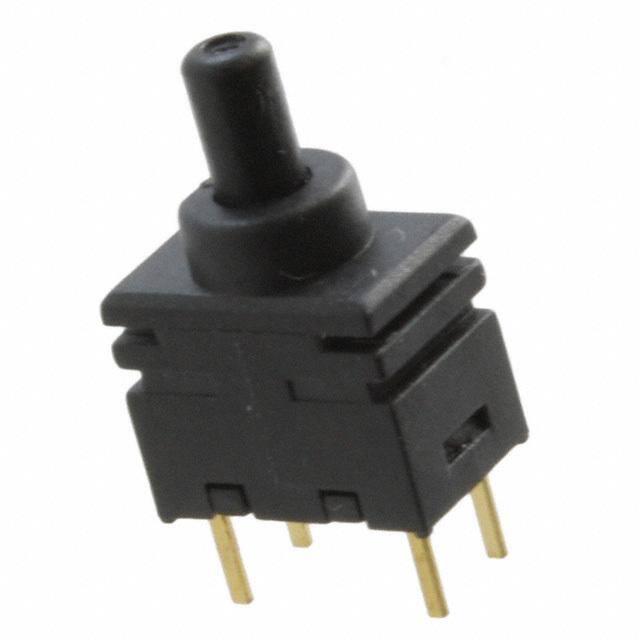
欧姆龙电子有限公司(Omron Electronics Inc.)EMC部门生产的按钮开关型号A9PS16-0011,属于工业控制元件,常用于需要手动控制电路通断的设备中。该型号具备良好的操作性能和可靠性,适用于多种工业和自动化场景。

典型应用场景包括:

1. 工业机械控制面板:用于机床、包装机械、输送设备等的操作面板上,实现启动、停止或紧急制动等功能。

2. 自动化生产线:在装配线或自动检测设备中作为手动干预按钮,便于操作员进行调试或复位操作。

3. 电力控制柜:应用于配电柜或控制柜中,作为电源开关或功能切换按钮,配合PLC或继电器系统使用。

4. 楼宇自动化系统:如电梯控制、门禁系统、照明控制系统中,用于人工指令输入。

5. 紧急停止系统:在需要安全防护的设备上作为紧急停止按钮,保障操作人员和设备安全。

该按钮开关具有标准尺寸、良好的耐久性和防水防尘性能(视具体配置),适用于较宽的温度范围,适合在工业环境中稳定使用。
| 参数 | 数值 |
| 产品目录 | |
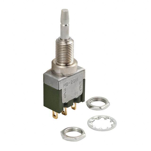
| 描述 | SWITCH PUSH SPST-NO 0.1A 28V按钮开关 Ultra Subminiature DIP Terminal, SPST |
| 产品分类 | |
| IP等级 | IP 64 |
| 品牌 | Omron Electronics |
| 产品手册 | |
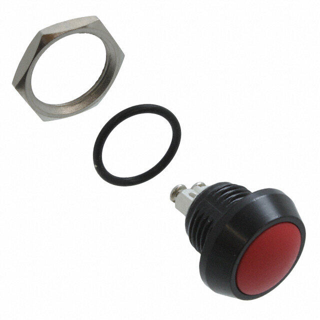
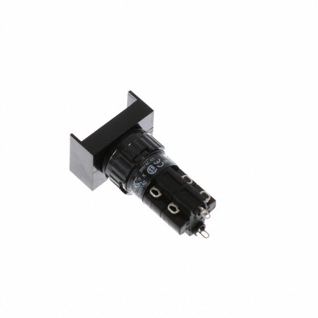
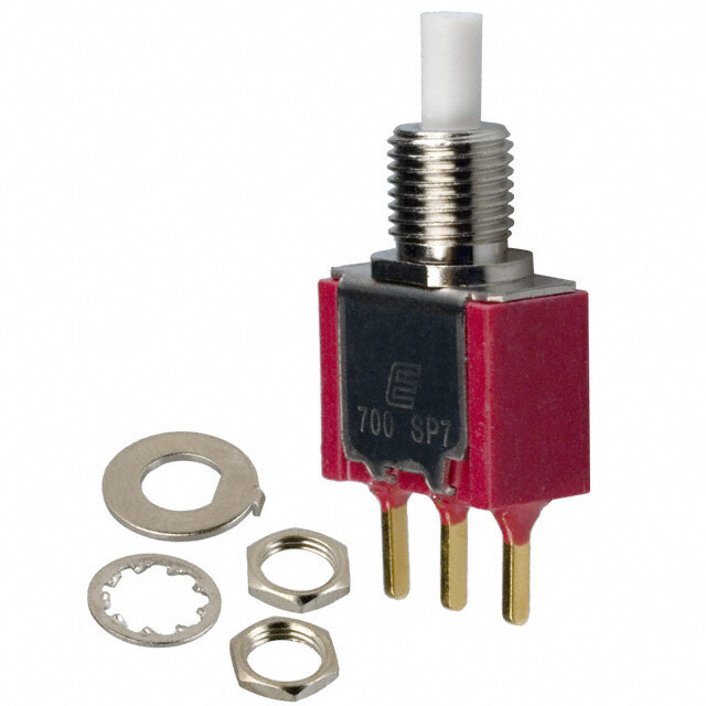
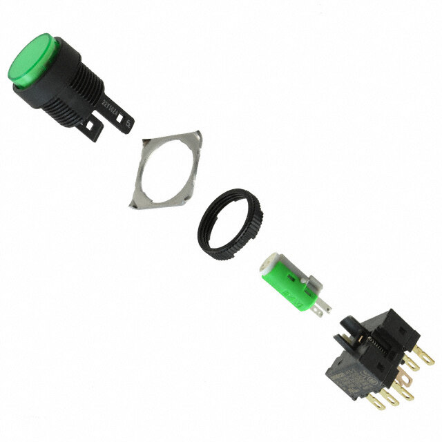
| 产品图片 |
|
| rohs | 符合RoHS无铅 / 符合限制有害物质指令(RoHS)规范要求 |
| 产品系列 | 按钮开关,Omron Electronics A9PS16-0011A9PS |
| mouser_ship_limit | 该产品可能需要其他文件才能进口到中国。 |
| 数据手册 | |
| 产品型号 | A9PS16-0011 |
| 产品种类 | |
| 侵入防护 | IP64 - 防尘,耐水 |
| 其它名称 | A9PS160011 |
| 其它有关文件 | |
| 包装 | 散装 |
| 商标 | Omron Electronics |
| 安装类型 | DIP |
| 安装风格 | Through Hole |
| 工作温度 | -20°C ~ 80°C |
| 工厂包装数量 | 100 |
| 开关功能 | OFF - (ON) |
| 执行器 | Plunger, with Cap |
| 机械寿命 | 50,000 次循环 |
| 标准包装 | 100 |
| 照明 | None |
| 照明电压(标称值) | - |
| 照明类型,颜色 | - |
| 特性 | 密封式 - 焊剂防护 |
| 电压额定值AC | 28 V |
| 电压额定值DC | 28 V |
| 电气寿命 | 50,000 次循环 |
| 电流额定值 | 100 mA |
| 电路 | SPST-NO |
| 盖颜色 | White |
| 端子类型 | PC 引脚 |
| 端接类型 | Solder Pin |
| 类型 | 标准 |
| 系列 | A9PS |
| 致动器类型 | 帽盖 |
| 触点形式 | SPST |
| 触点电镀 | Gold |
| 面板开口尺寸 | - |
| 颜色-致动器/盖帽 | - |
| 额定电压-AC | 28V |
| 额定电压-DC | 28V |
| 额定电流 | 100mA(AC/DC) |


- 商务部:美国ITC正式对集成电路等产品启动337调查
- 曝三星4nm工艺存在良率问题 高通将骁龙8 Gen1或转产台积电
- 太阳诱电将投资9.5亿元在常州建新厂生产MLCC 预计2023年完工
- 英特尔发布欧洲新工厂建设计划 深化IDM 2.0 战略
- 台积电先进制程称霸业界 有大客户加持明年业绩稳了
- 达到5530亿美元!SIA预计今年全球半导体销售额将创下新高
- 英特尔拟将自动驾驶子公司Mobileye上市 估值或超500亿美元
- 三星加码芯片和SET,合并消费电子和移动部门,撤换高东真等 CEO
- 三星电子宣布重大人事变动 还合并消费电子和移动部门
- 海关总署:前11个月进口集成电路产品价值2.52万亿元 增长14.8%


PDF Datasheet 数据手册内容提取
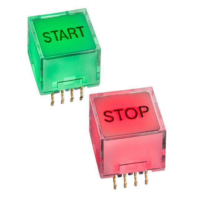
Ultra subminiature Pushbutton Switch A9PS Ultra subminiature size. ■ Gold-plated clip contact ensure high reliability. ■ The sealed bottom prevents flux penetration. ■ Washable, equivalent to IP64 (IEC-60529). ■ A9PS is smaller than A9P. Height: A9P 13.3mm, A9PS 10.5mm (30% smaller than A9P) RoHS Compliant Typical Applications Security Control Boards Electric Power Instrumentation Program Controllers Ordering Information Terminal Shape DIP Terminal Right Angle Terminal Vertical Mount Terminal Switching Functions SPST DPST SPST DPST SPST DPST OFF (ON) A9PS16-0011 A9PS26-0011 A9PS16-0012 A9PS26-0012 A9PS16-0013 A9PS26-0013 Quantity per tray 100 25 50 Note: (ON) shows Momentary. ● Caps Available wide range og colors. Colors White Black Blue Green Yellow Red Models A9PS-011 A9PS-021 A9PS-041 A9PS-051 A9PS-061 A9PS-071 4 dia. Dimension 2.4 Dimension with the cap. 3.8 2.4 4 dia. 1
A9PS A9PS Specifications ■ Ratings/Characteristics Switching capacity 100 mA at 28 VAC/DC, 0.1 μA (minimum current) at 20 mVAC/DC Ambient operating temperature −20 °C to 80 °C 60% RH max. (with no icing or condensation) Ambient operating humidity 45 to 85% RH (5 to 35 °C) Insulation resistance 500 MΩ min. (Initial value) Contact resistance 80 mΩ max. (Initial value) Dielectric strength 500 VAC for 1min between terminals, between terminals and ground Vibration resistance Malfunction: 10 to 55 Hz, 1.5-mm double amplitude Shock resistance Malufunction: 500 m/s2 min. Durability Mechanical: 50,000 operations min. Electrical: 50,000 operations min. Operating forcse 4.9 N max. Weight 0.3 g Dimensions Note: All units are in millimeters unless otherwise indicated. ● DIP Terminal Models 1.6 (5.6) 2.54 4.5 3.3 0.2 0.45 0.3 4 dia. (6) (3) (6) (3) 2 dia. 5.08 7 Stroke (4) (1) (4) (1) 0.3 1 1 Marking Side Single Pole Type Double Pole Type Note: NO.(4) and (6) terminals in the SPDT models are dummys to support the Switch case. ● Right Angle Terminal Models 5 1.6 (5.6) 4.5 3.3 0.2 0.45 4 dia. (3) (6) (3) 2 dia. 5.08 7 (1) (4) (1) 0.3 Stroke 1 1 Single Pole Type Double Pole Type Marking Side 0.3 2.6 3.1 5.08 2.54 2
A9PS A9PS ● Vertical Mount Terminal Models (5.6) 5.5 3.3 1.6 2.54 4.5 1 0.3 0.45 4 dia. (3) (6) (3) 2 dia. 7 (1) (4) (1) 0.3 Stroke 1 2.63.6 1 Marking Side Single Pole Type Double Pole Type 2.54 5.08 5.08 ● PCB Dimensions (Top View) DIP Terminal Models Right Angle Terminal Models 2F.5o4ur-0.6+ 00.1dia. 5.08 Four-0.6+ 00.1dia. 5.08 2S.5ix4-0.6+ 00.1dia. (3) (4) (3) (1) (6) 5.08 5.08 5.08 (1) (6) (1) (3) (4) Single Pole Type Double Pole Type Vertical Mount Terminal Models 2.54 2.54 5.08 5.08 (1) (4) (1) 5.08 5.08 (3) (6) (3) Four-0.6+ 00.1dia. Six-0.6+ 00.1dia. Single Pole Type Double Pole Type Switching Function / Internal Connections Switching Functions 1 1 SPST Models (3) (3) OFF (ON) 1 1 (3) (3) DPST Models 4 4 (6) (6) Note: (ON) shows Momentary. 3
A9PS A9PS Safety Precautions ● Cautions ● Using Flux Use the switch within the rated voltage and current ranges, Making mistakes in the type of flux or in the amount or method in otherwise the Switch may have a shortened life expectancy, which it is applied can cause flux to enter the interior of the radiate heat,or burn out. This particularly applies to the Switch, with adverse effects on Switch performance. Assess the instantaneous voltages and currents when switching. proper flux, conditions,and methods prior to using it. ● Hardling ● RoHS Compliant Do not apply excessive operating force to the Switch. Otherwise The "RoHS Compliant" designation indicates that the listed the Switch may be damaged or deformed, and the switch models do not contain the six hazardous substances covered by mechanism may malfunction as a result. Apply an operating force the RoHS Directive. not exceeding 9.8N {1,000gf}. Apply the operating load from the Reference: The following standards are used to determine top of the actuator. Do not apply a load from angle or from side compliance for the six substances. the actuator. Doing so may deform the Switch contact. •Lead: 1,000 ppm max. (cid:129)Mercury: 1,000 ppm max. ● Soldering (cid:129)Cadmium: 100 ppm max. Observe the following conditions when soldering the Switch. (cid:129)Hexavalent chromium: 1,000 ppm max. Automatic Soldering Bath (cid:129)PBB: 1,000 ppm max. Soldering temperature: 260 °C max. (Preheating: 100 °C 120s max.) (cid:129)PBDF: 1,000 ppm max. Soldering time: 5s max. Manual Soldering ● Environment for Storage and Use Soldering temperature: 350 °C at the tip of the soldering iron. To prevent discoloration of the terminals and other problems Soldering time: 3s max. during storage, do not store the Switch in locations subject to the following conditions. ● Washing 1. High temperature or humidity Apply alcohol based solvents to clean. 2. Corrosive gases Do not clean the Switch immediately after soldering. Wait for at 3. Direct sunlight least five minutes after soldering before cleaning. Also, the Switch is not waterproof or splash-resistance. Ultrasonic cleaning is not available dip into Switch washing Do not use the Switch in locations that are subject to contact with agents for two minutes maximum. water. Do not subject the Switch to freezing or condensation. ALL DIMENSIONS SHOWN ARE IN MILLIMETERS. To convert millimeters into inches, multiply by 0.03937. To convert grams into ounces, multiply by 0.03527. Cat. No. A198-E1-02 In the interest of product improvement, specifications are subject to change without notice. OMRON Corporation OMRON SWITCH & DEVICES Corporation Consumer & Commercial Switch Department Marketing 2075, Miyoshi, Nakaku, Okayama Okayama, 703-8502 Japan Printed in Japan Tel: (81)86-277-6024/Fax: (81)86-276-5044 0911 (0711) (W) URL : http://www.omron.com/ecb/
Mouser Electronics Authorized Distributor Click to View Pricing, Inventory, Delivery & Lifecycle Information: O mron: A9PS16-0011 A9PS16-0012 A9PS16-0013 A9PS26-0011 A9PS26-0012 A9PS26-0013 A9PS-011 A9PS-021 A9PS-051 A9PS-061