ICGOO在线商城 > 97-60-32(621)
.jpg)
 Datasheet下载
- 型号: 97-60-32(621)
- 制造商: Amphenol
- 库位|库存: xxxx|xxxx
- 要求:
| 数量阶梯 | 香港交货 | 国内含税 |
| +xxxx | $xxxx | ¥xxxx |
查看当月历史价格
查看今年历史价格
97-60-32(621)产品简介:
ICGOO电子元器件商城为您提供97-60-32(621)由Amphenol设计生产,在icgoo商城现货销售,并且可以通过原厂、代理商等渠道进行代购。 提供97-60-32(621)价格参考以及Amphenol97-60-32(621)封装/规格参数等产品信息。 你可以下载97-60-32(621)参考资料、Datasheet数据手册功能说明书, 资料中有97-60-32(621)详细功能的应用电路图电压和使用方法及教程。
| 参数 | 数值 |
| 产品目录 | |
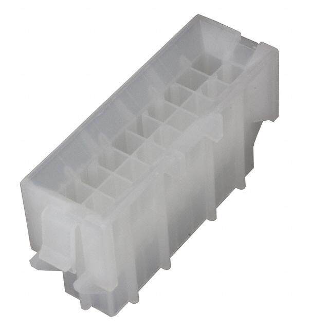
| 描述 | CONN CAP FOR SIZE 32 RECEPT |
| 产品分类 | |
| 品牌 | Amphenol Industrial Operations |
| 数据手册 | |
| 产品图片 |
|
| 产品型号 | 97-60-32(621) |
| rohs | 无铅 / 符合限制有害物质指令(RoHS)规范要求 |
| 产品系列 | 97 |
| 产品培训模块 | http://www.digikey.cn/PTM/IndividualPTM.page?site=cn&lang=zhs&ptm=22864 |
| 产品目录绘图 |
|
| 产品目录页面 | |
| 外壳尺寸-插件 | 32 |
| 材料 | 锌合金 |
| 标准包装 | 1 |
| 特性 | 金属链 |
| 配件类型 | 帽盖(盖) |
| 配套使用产品/相关产品 | MS3100、MS3101 和 MS3102 插座 |
| 颜色 | 黑 |


- 商务部:美国ITC正式对集成电路等产品启动337调查
- 曝三星4nm工艺存在良率问题 高通将骁龙8 Gen1或转产台积电
- 太阳诱电将投资9.5亿元在常州建新厂生产MLCC 预计2023年完工
- 英特尔发布欧洲新工厂建设计划 深化IDM 2.0 战略
- 台积电先进制程称霸业界 有大客户加持明年业绩稳了
- 达到5530亿美元!SIA预计今年全球半导体销售额将创下新高
- 英特尔拟将自动驾驶子公司Mobileye上市 估值或超500亿美元
- 三星加码芯片和SET,合并消费电子和移动部门,撤换高东真等 CEO
- 三星电子宣布重大人事变动 还合并消费电子和移动部门
- 海关总署:前11个月进口集成电路产品价值2.52万亿元 增长14.8%


PDF Datasheet 数据手册内容提取
Amphenol® 97 Series Standard Cylindrical Connector 12-022-15 MIL-5015 Style Connectors widely used for: • Factory Automation, Robotics (cid:127) Machine Tool, Instrumentation (cid:127) Welding Equipment (cid:127) Medical Equipment Amphenol® 97 Series Connectors are UL recognized and CSA recognized. Amphenol
Table of Contents Page Amphenol® 97 Series Standard Cylindrical Connectors – General Description. . . . . . . . . . . . . . . . . . . . . . . . . . . . . . . . . . . . . 1 Guide to Selecting a Connector. . . . . . . . . . . . . . . . . . . . . . . . . . . . . . . . . . . . . . . . . . . . . . . . . . . . . . . . . . . . . . . . . . . . . . . . . 2 Amphenol® 97 Series Connectors with Solder Contacts Design Characteristics, Customer Options. . . . . . . . . . . . . . . . . . . . . . . . . . . . . . . . . . . . . . . . . . . . . . . . . . . . . . . . . . . . . 3 Insert Availability. . . . . . . . . . . . . . . . . . . . . . . . . . . . . . . . . . . . . . . . . . . . . . . . . . . . . . . . . . . . . . . . . . . . . . . . . . . . . . . 4, 5 Contact Arrangements . . . . . . . . . . . . . . . . . . . . . . . . . . . . . . . . . . . . . . . . . . . . . . . . . . . . . . . . . . . . . . . . . . . . . . . . . .6-11 Alternate Insert Positioning. . . . . . . . . . . . . . . . . . . . . . . . . . . . . . . . . . . . . . . . . . . . . . . . . . . . . . . . . . . . . . . . . . . . . . . . 12 Receptacle Shell Styles . . . . . . . . . . . . . . . . . . . . . . . . . . . . . . . . . . . . . . . . . . . . . . . . . . . . . . . . . . . . . . . . . . . . . . . . . . 13 Solid Shell Plug Styles . . . . . . . . . . . . . . . . . . . . . . . . . . . . . . . . . . . . . . . . . . . . . . . . . . . . . . . . . . . . . . . . . . . . . . . . . . . 14 Split Shell Plug Styles. . . . . . . . . . . . . . . . . . . . . . . . . . . . . . . . . . . . . . . . . . . . . . . . . . . . . . . . . . . . . . . . . . . . . . . . . . . . 15 Weight Reference Charts . . . . . . . . . . . . . . . . . . . . . . . . . . . . . . . . . . . . . . . . . . . . . . . . . . . . . . . . . . . . . . . . . . . . . . .16-18 How to Order. . . . . . . . . . . . . . . . . . . . . . . . . . . . . . . . . . . . . . . . . . . . . . . . . . . . . . . . . . . . . . . . . . . . . . . . . . . . . . . . . . . 19 Amphenol® 97 Series Connectors with Rear Release Crimp Contacts Design Characteristics, Customer Options. . . . . . . . . . . . . . . . . . . . . . . . . . . . . . . . . . . . . . . . . . . . . . . . . . . . . . . . . . . . 20 Specifications and Insert Availability, Alternate Insert Positioning . . . . . . . . . . . . . . . . . . . . . . . . . . . . . . . . . . . . . . . . . . 21 Contact Arrangements . . . . . . . . . . . . . . . . . . . . . . . . . . . . . . . . . . . . . . . . . . . . . . . . . . . . . . . . . . . . . . . . . . . . . . . . 22, 23 Receptacle Shell Styles . . . . . . . . . . . . . . . . . . . . . . . . . . . . . . . . . . . . . . . . . . . . . . . . . . . . . . . . . . . . . . . . . . . . . . . . . . 24 Solid Shell Plug Styles . . . . . . . . . . . . . . . . . . . . . . . . . . . . . . . . . . . . . . . . . . . . . . . . . . . . . . . . . . . . . . . . . . . . . . . . . . . 25 Split Shell Plug Styles. . . . . . . . . . . . . . . . . . . . . . . . . . . . . . . . . . . . . . . . . . . . . . . . . . . . . . . . . . . . . . . . . . . . . . . . . . . . 26 How to Order. . . . . . . . . . . . . . . . . . . . . . . . . . . . . . . . . . . . . . . . . . . . . . . . . . . . . . . . . . . . . . . . . . . . . . . . . . . . . . . . . . . 27 Crimp Contact Information . . . . . . . . . . . . . . . . . . . . . . . . . . . . . . . . . . . . . . . . . . . . . . . . . . . . . . . . . . . . . . . . . . . . . . . . 28 Crimp Contact Information cont., Tools. . . . . . . . . . . . . . . . . . . . . . . . . . . . . . . . . . . . . . . . . . . . . . . . . . . . . . . . . . . . . . . 29 Special Purpose Connectors Potting Construction . . . . . . . . . . . . . . . . . . . . . . . . . . . . . . . . . . . . . . . . . . . . . . . . . . . . . . . . . . . . . . . . . . . . . . . . . . . . . 30 Box Type Plugs, Small Flange Receptacles. . . . . . . . . . . . . . . . . . . . . . . . . . . . . . . . . . . . . . . . . . . . . . . . . . . . . . . . . . . 31 ECG Connector, Convenience Outlets. . . . . . . . . . . . . . . . . . . . . . . . . . . . . . . . . . . . . . . . . . . . . . . . . . . . . . . . . . . . . . . 32 97 Series Accessories Cable Clamps, Bushing. . . . . . . . . . . . . . . . . . . . . . . . . . . . . . . . . . . . . . . . . . . . . . . . . . . . . . . . . . . . . . . . . . . . . . . . .33,34 Protection Caps . . . . . . . . . . . . . . . . . . . . . . . . . . . . . . . . . . . . . . . . . . . . . . . . . . . . . . . . . . . . . . . . . . . . . . . . . . . . . 35, 36 Adapters . . . . . . . . . . . . . . . . . . . . . . . . . . . . . . . . . . . . . . . . . . . . . . . . . . . . . . . . . . . . . . . . . . . . . . . . . . . . . . . . . . . . . . 37 Conduit Box Connector, Conduit Coupling Nuts, . . . . . . . . . . . . . . . . . . . . . . . . . . . . . . . . . . . . . . . . . . . . . . . . . . . . . . . 38 Sealing Gaskets . . . . . . . . . . . . . . . . . . . . . . . . . . . . . . . . . . . . . . . . . . . . . . . . . . . . . . . . . . . . . . . . . . . . . . . . . . . . . . . . 39 Dummy Receptacles. . . . . . . . . . . . . . . . . . . . . . . . . . . . . . . . . . . . . . . . . . . . . . . . . . . . . . . . . . . . . . . . . . . . . . . . . . . . . 40 Additional Products . . . . . . . . . . . . . . . . . . . . . . . . . . . . . . . . . . . . . . . . . . . . . . . . . . . . . . . . . . . . . . . . . . . . . . . . . . . . . . 41, 42 Sales Office Listing Amphenol Aerospace operates Quality Systems that are Certified to ISO-9001 and AS-9100 by third party Registrars.
Amphenol ® 97 Series Connectors provide the interconnection solution for low cost, general duty applications Amphenol offers the 97 Series Connector Family - A general duty standard cylindrical connector, MIL-5015 style. The 97 Series is a widely used connector series for the auto- motive, robotics, machine tool and welding industries, as well as numerous other commercial applications from heavy equip- ment to ECG monitoring cables. Shell components are fabricated from high grade aluminum alloy to provide strength and environmental protection. This family of connectors offers a wide variety of shell styles, con- tact patterns and accessory options. The Amphenol® 97 Series design features and benefits: (cid:127) Low cost, general duty non-environmental (cid:127) Environmental capability with the 417 suffix plus 9767 cable clamp (see page 34) (cid:127) Solder or crimp termination (cid:127) UL Recognized, CSA Recognized (cid:127) Wide selection of shell styles and insert patterns (cid:127) Wide selection of connector finishes - cadmium or non-cadmium (environmentally friendly zinc alloy) (cid:127) Threaded coupling, hard dielectric inserts (cid:127) Solid or split shell construction (cid:127) Accessories for both individual wire seal and jacketed cable RoHS COMPLIANT PRODUCT AVAILABLE – Consult A mphenol HS Amphenol Industrial Operations. R o EU/2002/95/EC For additional information on Amphenol® 97 Series connectors, or for special application requirements, contact your local Amphenol sales office, authorized distributor, or - Amphenol Corporation Amphenol Industrial Operations 40-60 Delaware Avenue Sidney, New York 13838-1395 Telephone: 607-563-5011 Fax: 607-563-5157 Web site: www.amphenol-industrial.com 1
Guide to Selecting a Connector In selecting a connector, it first must be The others have low current functions. after the main shell type number: for determined if a non-environmental 97 A plug mated with the wrong receptacle example, 3106A or 3108A. A or B Series 5015 type is required or if (cross-mating) could ruin your valu- The designation for split shell construc- an environmental MS-5015 Class E, F, able equipment. tion is the letter B; for example, 3106B or R type* is required. To avoid cross-mating, you can or 3108B. If determined that the general duty, order identical inserts positioned in Because of application, receptacles non-environmental 97 series is the both the plugs and receptacles at vari- are made in solid backshell construc- choice - then this catalog is appropriate ous angles from standard. These varia- tion only. Their designation is 3100A, to your needs tions from standard position are called 3101A. (See how to order for solder The following 8 steps apply to for- alternate insert positions, and are contact connectors, page 19. mulation of a part number.** described on page 12. 6 Which connector gets the 1 How many wires are you 3 What kind of receptacle do socket? - the receptacle or going to connect? you need? the plug? What gauge? For Wall Mounting Use a wall recep- You’re at the point where you desig- These two questions are important, tacle, type 3100. The elongated back of nate which inserts are used with which because they indicate which insert you this receptacle extends through thick shells. Either pin or socket inserts can need. There are literally hundreds to wall material. It is threaded to accept be used with plugs or receptacles. choose from. standard hardware fittings. Here’s a good rule of thumb. Order The insert arrangements for solder For Unmounted Applications Use the sockets for the connector at the contact connectors are illustrated on the cable receptacle, type 3101. “hot” side of the circuit. By having sock- pages 6-11. The inserts most often For Box or Panel Mounting Use the ets at the power source, there’s little used are highlighted on these pages. box receptacle, type 3102. This recep- chance that a wayward finger or screw- Here’s an example of how to choose tacle’s back is short to conserve space. driver will short the circuit or cause per- an insert arrangement. Say you want to It is not threaded on the back end and sonal injury. connect eight 16-ga. wires, - first find is used when no accessories such as The designation for sockets is sim- the section of arrangements contain- clamps are needed. ply S in a part number, following the ing 8 contacts. Insert number 20-7 is 4 What kind of plug do you insert code number. For pins, the des- the one you want because it contains need? ignation is P. Therefore, the 20-7P eight 16-ga. contacts and it is one of insert would have pin contacts, while For ordinary situations The straight the most often used. The one you the 20-7S insert would have socket plug, type 3106 meets most connector choose might depend on your space or contacts. requirements. However . . . voltage requirements. The voltage 7 What type of plating is pre- when space is critical you may want capacity of each insert is listed under ferred? to consider using an angle plug, type its diagram. 3108. This type plug lets the cable If you prefer the standard olive cad- If you have more than one wire size enter your equipment at a right angle. mium, non-reflective, electrically con- to connect, the method is essentially the same. Actually, the insert configu- 5 Do you need a plug with a ductive finish, then no suffix number is required. Other plating variations are rations for multiple-size wires are a lot Solid or Split back shell? available, including environmentally more flexible than they appear. That’s You can get both straight and angle friendly zinc alloy. See how to order because you can always solder a plugs in solid or split back shell instructions for the various plating fin- smaller wire to a larger contact. How- designs. With the solid shell you have ishes offered for 97 Series solder con- ever, soldering a large wire to a small greater strength and you save space. nectors on page 19. contact isn’t recommended because of On the other hand, the split shell size and current requirements. design lets you quickly inspect the sol- 8 Do you need any accessories? 2 What if several identical der terminals when you need to. This connectors have different feature could be important if you’ll be Accessories - cable clamps, protection functions? subjecting the connector to rough han- caps and chains, conduit adapters, and dling and heavy use. panel gaskets are shown on pages 33- Here’s a situation to watch out for. You The designation to use for solid 39. have four identical receptacles on a shell construction is the letter A. This panel. One carries high current loads. designation letter goes immediately * If an environmental type MIL-5015 E, F or R Class is required, then the ** These steps are for solder type connectors which are described in catalog that should be consulted is 12-020, MS/Standard MIL-5015 detail on pages 3-19. If a crimp type connector is needed, the same Cylindrical Connectors. See www.amphenol-industrial.com for on-line 2 steps apply, however, you should consult pages 20-29 for details on 97 catalogs or contact Amphenol, Sidney, NY. Series connectors with crimp contacts.
Amphenol ® 97 Series Connectors with solder contacts DESIGN CHARACTERISTICS (cid:127) Medium to heavy weight cylindrical (cid:127) Durable, field-proven design (cid:127) Single key/keyway polarization (cid:127) Threaded coupling, hard dielectric inserts (cid:127) Non-rotating contacts (cid:127) Operating temperatures from –55°C to +125°C (cid:127) Cost effective MS3100A (cid:127) Intermateable and intermountable with existing 97 Series and MIL-5015 connectors MS3107A (cid:127) Underwriters Laboratories approved recogni- tion File E115497 (cid:127) Canadian Standards Association Certification File LR69183 CUSTOMER OPTIONS MS3101A (cid:127) Solid or split shell construction (cid:127) Six shell styles (cid:127) 128 contact arrangements, from 1 to 52 circuits MS3107B (cid:127) Alternate insert positioning (cid:127) High temperature and potting constructions (cid:127) Special plating finishes including black and green zinc alloy (cid:127) Optional gold plating on MS contacts MS3102A (cid:127) Thermocouple arrangements available Connector components are fabricated from high grade aluminum alloy, with a conductive cadmium plate finish and an olive drab chromate after-treatment. Some cable MS3108A clamps are a zinc alloy with an olive drab/green chromate finish. See how to order page 19 for other finish varia- tions. Contacts are silver plated with pre-tinned solder cups. Optional gold over silver plating is also available. Inserts MS3106A for solder style contacts are diallyl-phthalate. Users should be aware that classes “A” and “B” of MIL- 5015 have been cancelled, and these products are no longer qualified. MS3108B MS3106B 3
97 series solder type insert availability Mechanical Mechanical Insert Number Total Spacing Service Contact Size Insert Number Total Spacing Service Contact Size Contacts Rating Contacts Rating Inches mm 0 4 8 12 16 Inches mm 0 4 8 12 16 8S-1✦ 1 1/16 1.57 INST. 1 20-4 4 1/8 3.18 D 4 10SL-3 3 1/16 1.57 A 3 20-6† 3 1/8 3.18 D 3 10SL-4 2 1/16 1.57 A 2 1/8 3.18 D 4 20-7 8 12SL-844✦* 4 1/16 1.57 A 4 1/16 1.57 A 4 12S-3 2 1/16 1.57 A 2 20-8 6 INST. 2 4 12-5✦ 1 1/8 3.18 D 1 20-11† 13 INST. 13 2 20-14 5 1/16 1.57 A 2 3 12S-6✦* 2 1/16 1.57 (cid:54)(cid:74)(cid:71)(cid:84)(cid:79)(cid:81)(cid:15) 20-15 7 1/16 1.57 A 7 (cid:69)(cid:81)(cid:87)(cid:82)(cid:78)(cid:71) 14S-1† 3 1/16 1.57 A 3 20-16 9 1/16 1.57 A 2 7 14S-2 4 INST. 4 20-17 6 1/16 1.57 A 5 1 14S-4✦† 1 1/8 3.18 D 1 20-18 9 1/16 1.57 A 3 6 14S-5 5 INST 5 20-19† 3 1/16 1.57 A 3 14S-6 6 INST. 6 20-21 9 1/16 1.57 A 1 8 14S-7 3 1/16 1.57 A 3 20-23 2 1/16 1.57 A 2 14S-9† 2 1/16 1.57 A 2 20-24 4 1/16 1.57 A 2 2 16S-1 7 1/16 1.57 A 7 20-27 14 1/16 1.57 A 14 16S-4✦ 2 1/8 3.18 D 2 20-29 17 1/16 1.57 A 17 16S-5 3 1/16 1.57 A 3 20-33 11 1/16 1.57 A 11 16S-6✦† 3 1/16 1.57 A 3 22-1† 2 1/8 3.18 D 2 16-7 3 1/16 1.57 A 1 2 22-2 3 1/8 3.18 D 3 16S-8 5 1/16 1.57 A 5 22-4† 4 1/16 1.57 A 2 2 16-9 4 1/16 1.57 A 2 2 22-5 6 1/8 3.18 D 2 4 16-10 3 1/16 1.57 A 3 22-8† 2 3/16 4.75 E 2 16-11✦† 2 1/16 1.57 A 2 22-9 3 3/16 4.75 E 3 16-12 1 1/16 1.57 A 1 22-10 4 3/16 4.75 E 4 2 22-11 2 1/4 6.35 B 2 16-13 2 1/16 1.57 A (cid:54)(cid:74)(cid:71)(cid:84)(cid:79)(cid:81)(cid:15) 22-12 5 1/8 3.18 D 2 3 (cid:69)(cid:81)(cid:87)(cid:82)(cid:78)(cid:71) 1/8 3.18 D 1 A 4 22-13† 5 18-1 10 1/16 1.57 1/16 1.57 A 4 INST. 6 22-14 19 1/16 1.57 A 19 18-3† 2 1/8 3.18 D 2 3/16 4.75 E 1 18-4 4 1/8 3.18 D 4 22-15 6 1/16 1.57 A 5 18-5✦ 3 1/8 3.18 D 2 1 22-16† 9 1/16 1.57 A 3 6 18-8 8 1/16 1.57 A 1 7 1/8 3.18 D 5 18-9✦ 7 INST. 2 5 22-18 8 1/16 1.57 A 3 18-10† 4 1/16 1.57 A 4 22-19 14 1/16 1.57 A 14 18-11 5 1/16 1.57 A 5 22-20† 9 1/16 1.57 A 9 18-12† 6 1.16 1.57 A 6 22-22 4 1/16 1.57 A 4 18-13 4 1/16 1.57 A 1 3 1/8 3.18 D 1 18-16 1 5/16 7.92 C 1 22-23 8 1/16 1.57 A 7 18-19† 10 1/16 1.57 A 10 18-20 5 1/16 1.57 A 5 18-22† 3 1/8 3.18 D 3 Not all insert arrangements are currently available for environmental individual 18-29✦† 5 1/16 1.57 A 5 wire seal. Consult Amphenol, Sidney, NY for availability. 1 † Inactive for new military design, but available for replacement or for non-mili- 18-420* 1 (cid:42)(cid:75)(cid:15)(cid:56)(cid:81)(cid:78)(cid:86)(cid:15) tary purposes. (cid:67)(cid:73)(cid:71)(cid:12)(cid:12) * “MS” number not assigned. Use “97” prefix in place of “MS” in completing cata- 20-3† 3 1/8 3.18 D 3 log number. See how to order, page 19. ** Hi-Voltage = 17KVAC/24KVDC ✦ Molded-in pin (MIP) insert requires (910) deviation. See how to order, pg. 19. 4
97 series solder type insert availability, cont. Mechanical Mechanical Insert Total Spacing Service Contact Size Insert Total Spacing Service Contact Size Number Contacts Rating Number Contacts Rating Inches mm 0 4 8 12 16 Inches mm 0 4 8 12 16 22-26* 7 1/8 3.18 2 5 28-20 14 1/16 1.57 A 10 4 1/8 3.18 D 1 28-21 37 1/16 1.57 A 37 22-27 9 1/16 1.57 A 8 32-5† 2 1/8 3.18 D 2 22-28† 7 1/16 1.57 A 7 32-6 23 1/16 1.57 A 2 3 2 16 22-34 5 1/8 3.18 D 3 2 1/16 1.57 A 7 24 32-7 35 24-2 7 1/8 3.18 D 7 INST. 4 24-5† 16 1/16 1.57 A 16 32-8† 30 1/16 1.57 A 6 24 1/8 3.18 D 3 32-13 23 1/8 3.18 D 5 18 24-6 8 1/16 1.57 A 5 32-17 4 1/8 3.18 D 4 24-7 16 1/16 1.57 A 2 14 32-414 52 1/16 1.57 A 52 24-9† 2 1/16 1.57 A 2 36-1† 22 1/8 3.18 D 4 18 24-10 7 1/16 1.57 A 7 36-5 4 1/16 1.57 A 4 24-11 9 1/16 1.57 A 3 6 36-6 6 1/16 1.57 A 2 4 24-12 5 1/16 1.57 A 2 3 36-7 47 1/16 1.57 A 7 40 1/8 3.18 D 1 3 36-8 47 1/16 1.57 A 1 46 24-16 7 1/16 1.57 A 3 36-9 31 1/16 1.57 A 1 2 14 14 24-19† 12 1/16 1.57 12 36-10 48 1/16 1.57 A 48 24-20✦ 11 1/8 3.18 D 2 9 1/16 1.57 A 34 36-15 35 24-21 10 1/8 3.18 D 1 9 1/8 3.18 D 1 24-22✦ 4 1/8 3.18 D 4 36-403* 52 1/16 1.57 A 52 24-27 7 3/16 4.75 E 7 24-28 24 1/16 1.57 INST. 24 1/8 3.18 D 1 2 28-1 9 1/16 1.57 A 2 4 28-2 14 1/8 3.18 D 2 12 28-3 3 3/16 4.75 E 3 28-6† 3 1/8 3.18 D 3 1/16 1.57 A 9 28-8 12 1/8 3.18 D 1 3/16 4.75 E 2 28-9 12 1/8 3.18 D 6 6 1/8 3.18 D 1 28-10 7 1/16 1.57 A 2 2 2 28-11 22 1/16 1.57 A 4 18 28-12 26 1/16 1.57 A 26 28-15† 35 1/16 1.57 A 35 28-16† 20 1/16 1.57 A 20 1/4 6.35 B 1 28-17 15 1/8 3.18 D 3 1/16 1.57 A 11 5/16 7.92 C 1 1/8 3.18 D 5 28-18 12 1/16 1.57 A 2 Not all insert arrangements are currently available for environmental individual wire seal. Consult Amphenol, Sidney, NY for availability. INST. 4 † Inactive for new military design, but available for replacement or for non-mili- 1/4 6.35 B 2 tary purposes. * “MS” number not assigned. Use “97” prefix in place of “MS” in completing cata- 28-19 10 1/8 3.18 D 2 log number. See how to order, page 19. 1/16 1.57 A 4 2 ✦ Molded-in pin (MIP) insert requires (910) deviation. See how to order, pg. 19. 5
97 series solder type insert arrangements Front view of pin insert or rear of socket insert illustrated. Items highlighted are most popular and most readily available. 1 Contact (cid:43)(cid:80)(cid:85)(cid:71)(cid:84)(cid:86)(cid:2)(cid:35)(cid:84)(cid:84)(cid:67)(cid:80)(cid:73)(cid:71)(cid:79)(cid:71)(cid:80)(cid:86) (cid:26)(cid:53)(cid:15)(cid:19) (cid:19)(cid:20)(cid:15)(cid:23) (cid:19)(cid:22)(cid:53)(cid:15)(cid:22)(cid:340) (cid:19)(cid:24)(cid:15)(cid:19)(cid:20) (cid:19)(cid:26)(cid:15)(cid:19)(cid:24) (cid:19)(cid:26)(cid:15)(cid:22)(cid:20)(cid:18)(cid:12) (cid:37)(cid:81)(cid:80)(cid:86)(cid:67)(cid:69)(cid:86)(cid:85) (cid:19)(cid:5)(cid:19)(cid:24) (cid:19)(cid:5)(cid:19)(cid:20) (cid:19)(cid:5)(cid:19)(cid:24) (cid:19)(cid:5)(cid:22) (cid:19)(cid:5)(cid:19)(cid:20) (cid:19)(cid:5)(cid:19)(cid:20) (cid:53)(cid:71)(cid:84)(cid:88)(cid:75)(cid:69)(cid:71)(cid:2)(cid:52)(cid:67)(cid:86)(cid:75)(cid:80)(cid:73) (cid:43)(cid:48)(cid:53)(cid:54)(cid:16) (cid:38) (cid:38) (cid:35) (cid:37) (cid:42)(cid:75)(cid:73)(cid:74)(cid:2)(cid:56)(cid:81)(cid:78)(cid:86)(cid:67)(cid:73)(cid:71) (cid:19)(cid:25)(cid:45)(cid:56)(cid:35)(cid:37)(cid:17)(cid:20)(cid:22)(cid:45)(cid:56)(cid:38)(cid:37) 2 Contacts AB B A B A B A B A A B A B (cid:43)(cid:80)(cid:85)(cid:71)(cid:84)(cid:86)(cid:2)(cid:35)(cid:84)(cid:84)(cid:67)(cid:80)(cid:73)(cid:71)(cid:79)(cid:71)(cid:80)(cid:86) (cid:19)(cid:18)(cid:53)(cid:46)(cid:15)(cid:22) (cid:19)(cid:20)(cid:53)(cid:15)(cid:21) (cid:19)(cid:20)(cid:53)(cid:15)(cid:24)(cid:12) (cid:19)(cid:22)(cid:53)(cid:15)(cid:27)(cid:340) (cid:19)(cid:24)(cid:53)(cid:15)(cid:22) (cid:19)(cid:24)(cid:15)(cid:19)(cid:19)(cid:340) (cid:19)(cid:24)(cid:15)(cid:19)(cid:21) (cid:37)(cid:81)(cid:80)(cid:86)(cid:67)(cid:69)(cid:86)(cid:85) (cid:20)(cid:5)(cid:19)(cid:24) (cid:20)(cid:5)(cid:19)(cid:24) (cid:20)(cid:5)(cid:19)(cid:24) (cid:20)(cid:5)(cid:19)(cid:24) (cid:20)(cid:5)(cid:19)(cid:24) (cid:20)(cid:5)(cid:19)(cid:20) (cid:20)(cid:5)(cid:19)(cid:20) (cid:53)(cid:71)(cid:84)(cid:88)(cid:75)(cid:69)(cid:71)(cid:2)(cid:52)(cid:67)(cid:86)(cid:75)(cid:80)(cid:73) (cid:35) (cid:35) (cid:54)(cid:74)(cid:71)(cid:84)(cid:79)(cid:81)(cid:69)(cid:81)(cid:87)(cid:82)(cid:78)(cid:71) (cid:35) (cid:38) (cid:35) (cid:35) A B A A B A B A B A B A B B (cid:43)(cid:80)(cid:85)(cid:71)(cid:84)(cid:86)(cid:2)(cid:35)(cid:84)(cid:84)(cid:67)(cid:80)(cid:73)(cid:71)(cid:79)(cid:71)(cid:80)(cid:86) (cid:19)(cid:26)(cid:15)(cid:21)(cid:340) (cid:20)(cid:18)(cid:15)(cid:20)(cid:21)(cid:340) (cid:20)(cid:20)(cid:15)(cid:19)(cid:340) (cid:20)(cid:20)(cid:15)(cid:26)(cid:340) (cid:20)(cid:20)(cid:15)(cid:19)(cid:19) (cid:20)(cid:22)(cid:15)(cid:27)(cid:340) (cid:21)(cid:20)(cid:15)(cid:23)(cid:340) (cid:37)(cid:81)(cid:80)(cid:86)(cid:67)(cid:69)(cid:86)(cid:85) (cid:20)(cid:5)(cid:19)(cid:20) (cid:20)(cid:5)(cid:26) (cid:20)(cid:5)(cid:26) (cid:20)(cid:5)(cid:19)(cid:20) (cid:20)(cid:5)(cid:19)(cid:24) (cid:20)(cid:5)(cid:22) (cid:20)(cid:5)(cid:18) (cid:53)(cid:71)(cid:84)(cid:88)(cid:75)(cid:69)(cid:71)(cid:2)(cid:52)(cid:67)(cid:86)(cid:75)(cid:80)(cid:73) (cid:38) (cid:35) (cid:38) (cid:39) (cid:36) (cid:35) (cid:38) 3 Contacts CB A CBA CBA C AB C BA A CB C BA C BA A GB (cid:43)(cid:80)(cid:85)(cid:71)(cid:84)(cid:86)(cid:2)(cid:35)(cid:84)(cid:84)(cid:67)(cid:80)(cid:73)(cid:71)(cid:79)(cid:71)(cid:80)(cid:86) (cid:19)(cid:18)(cid:53)(cid:46)(cid:15)(cid:21) (cid:19)(cid:22)(cid:53)(cid:15)(cid:19)(cid:340) (cid:19)(cid:22)(cid:53)(cid:15)(cid:25) (cid:19)(cid:24)(cid:53)(cid:15)(cid:23)(cid:340) (cid:19)(cid:24)(cid:53)(cid:15)(cid:24)(cid:340) (cid:19)(cid:24)(cid:15)(cid:25) (cid:19)(cid:24)(cid:15)(cid:19)(cid:18) (cid:19)(cid:26)(cid:15)(cid:23) (cid:19)(cid:26)(cid:15)(cid:20)(cid:20)(cid:340) (cid:37)(cid:81)(cid:80)(cid:86)(cid:67)(cid:69)(cid:86)(cid:85) (cid:21)(cid:5)(cid:19)(cid:24) (cid:21)(cid:5)(cid:19)(cid:24) (cid:21)(cid:5)(cid:19)(cid:24) (cid:21)(cid:5)(cid:19)(cid:24) (cid:21)(cid:5)(cid:19)(cid:24) (cid:19)(cid:5)(cid:26)(cid:14)(cid:2)(cid:20)(cid:5)(cid:19)(cid:24) (cid:21)(cid:5)(cid:19)(cid:20) (cid:20)(cid:5)(cid:19)(cid:20)(cid:14)(cid:2)(cid:19)(cid:5)(cid:19)(cid:24) (cid:21)(cid:5)(cid:19)(cid:24) (cid:53)(cid:71)(cid:84)(cid:88)(cid:75)(cid:69)(cid:71)(cid:2)(cid:52)(cid:67)(cid:86)(cid:75)(cid:80)(cid:73) (cid:35) (cid:35) (cid:35) (cid:35) (cid:35) (cid:35) (cid:35) (cid:38) (cid:38) A A A A A A A C B C B C B C B C B C B C B (cid:43)(cid:80)(cid:85)(cid:71)(cid:84)(cid:86)(cid:2)(cid:35)(cid:84)(cid:84)(cid:67)(cid:80)(cid:73)(cid:71)(cid:79)(cid:71)(cid:80)(cid:86) (cid:20)(cid:18)(cid:15)(cid:21)(cid:340) (cid:20)(cid:18)(cid:15)(cid:24)(cid:340) (cid:20)(cid:18)(cid:15)(cid:19)(cid:27)(cid:340) (cid:20)(cid:20)(cid:15)(cid:20) (cid:20)(cid:20)(cid:15)(cid:27) (cid:20)(cid:26)(cid:15)(cid:21) (cid:20)(cid:26)(cid:15)(cid:24)(cid:340) (cid:37)(cid:81)(cid:80)(cid:86)(cid:67)(cid:69)(cid:86)(cid:85) (cid:21)(cid:5)(cid:19)(cid:20) (cid:21)(cid:5)(cid:19)(cid:24) (cid:21)(cid:5)(cid:26) (cid:21)(cid:5)(cid:26) (cid:21)(cid:5)(cid:19)(cid:20) (cid:21)(cid:5)(cid:26) (cid:21)(cid:5)(cid:22) (cid:53)(cid:71)(cid:84)(cid:88)(cid:75)(cid:69)(cid:71)(cid:2)(cid:52)(cid:67)(cid:86)(cid:75)(cid:80)(cid:73) (cid:38) (cid:38) (cid:35) (cid:38) (cid:39) (cid:39) (cid:38) 6
97 series solder type insert arrangements, cont. Front view of pin insert or rear of socket insert illustrated. Items highlighted are most popular and most readily available. 4 Contacts DA DA A D A D D A D D A C C B C B C B C B C B B A C B (cid:43)(cid:80)(cid:85)(cid:71)(cid:84)(cid:86)(cid:2)(cid:35)(cid:84)(cid:84)(cid:67)(cid:80)(cid:73)(cid:71)(cid:79)(cid:71)(cid:80)(cid:86) (cid:19)(cid:20)(cid:53)(cid:46)(cid:15)(cid:26)(cid:22)(cid:22)(cid:12) (cid:19)(cid:22)(cid:53)(cid:15)(cid:20)(cid:340) (cid:19)(cid:24)(cid:15)(cid:27) (cid:19)(cid:26)(cid:15)(cid:22) (cid:19)(cid:26)(cid:15)(cid:19)(cid:18)(cid:340) (cid:19)(cid:26)(cid:15)(cid:19)(cid:21) (cid:20)(cid:18)(cid:15)(cid:22) (cid:37)(cid:81)(cid:80)(cid:86)(cid:67)(cid:69)(cid:86)(cid:85) (cid:22)(cid:5)(cid:19)(cid:24) (cid:22)(cid:5)(cid:19)(cid:24) (cid:20)(cid:5)(cid:19)(cid:20)(cid:14)(cid:2)(cid:20)(cid:5)(cid:19)(cid:24) (cid:22)(cid:5)(cid:19)(cid:24) (cid:22)(cid:5)(cid:19)(cid:20) (cid:21)(cid:5)(cid:19)(cid:20)(cid:14)(cid:2)(cid:19)(cid:5)(cid:26) (cid:22)(cid:5)(cid:19)(cid:20) (cid:53)(cid:71)(cid:84)(cid:88)(cid:75)(cid:69)(cid:71)(cid:2)(cid:52)(cid:67)(cid:86)(cid:75)(cid:80)(cid:73) (cid:19)(cid:17)(cid:19)(cid:24)(cid:338)(cid:2)(cid:85)(cid:82)(cid:67)(cid:69)(cid:75)(cid:80)(cid:73) (cid:43)(cid:48)(cid:53)(cid:54)(cid:16) (cid:35) (cid:38) (cid:35) (cid:35) (cid:38) D A D A D A D A D A D A D A B B C C C C C B B B B C B C (cid:43)(cid:80)(cid:85)(cid:71)(cid:84)(cid:86)(cid:2)(cid:35)(cid:84)(cid:84)(cid:67)(cid:80)(cid:73)(cid:71)(cid:79)(cid:71)(cid:80)(cid:86) (cid:20)(cid:18)(cid:15)(cid:20)(cid:22) (cid:20)(cid:20)(cid:15)(cid:22)(cid:340) (cid:20)(cid:20)(cid:15)(cid:19)(cid:18) (cid:20)(cid:20)(cid:15)(cid:20)(cid:20) (cid:20)(cid:22)(cid:15)(cid:20)(cid:20) (cid:21)(cid:20)(cid:15)(cid:19)(cid:25) (cid:21)(cid:24)(cid:15)(cid:23) (cid:37)(cid:81)(cid:80)(cid:86)(cid:67)(cid:69)(cid:86)(cid:85) (cid:20)(cid:5)(cid:26)(cid:14)(cid:2)(cid:20)(cid:5)(cid:19)(cid:24) (cid:20)(cid:5)(cid:26)(cid:14)(cid:2)(cid:20)(cid:5)(cid:19)(cid:20) (cid:22)(cid:5)(cid:19)(cid:24) (cid:22)(cid:5)(cid:26) (cid:22)(cid:5)(cid:26) (cid:22)(cid:5)(cid:22) (cid:22)(cid:5)(cid:18) (cid:53)(cid:71)(cid:84)(cid:88)(cid:75)(cid:69)(cid:71)(cid:2)(cid:52)(cid:67)(cid:86)(cid:75)(cid:80)(cid:73) (cid:35) (cid:35) (cid:39) (cid:35) (cid:38) (cid:38) (cid:35) 5 Contacts DAE BC CD AEB CD BEA AE BD C D CE BA DC E AB (cid:43)(cid:80)(cid:85)(cid:71)(cid:84)(cid:86)(cid:2)(cid:35)(cid:84)(cid:84)(cid:67)(cid:80)(cid:73)(cid:71)(cid:79)(cid:71)(cid:80)(cid:86) (cid:19)(cid:22)(cid:53)(cid:15)(cid:23) (cid:19)(cid:24)(cid:53)(cid:15)(cid:26) (cid:19)(cid:26)(cid:15)(cid:19)(cid:19) (cid:19)(cid:26)(cid:15)(cid:20)(cid:18)(cid:340) (cid:19)(cid:26)(cid:15)(cid:20)(cid:27)(cid:340) (cid:20)(cid:18)(cid:15)(cid:19)(cid:22) (cid:37)(cid:81)(cid:80)(cid:86)(cid:67)(cid:69)(cid:86)(cid:85) (cid:23)(cid:5)(cid:19)(cid:24) (cid:23)(cid:5)(cid:19)(cid:24) (cid:23)(cid:5)(cid:19)(cid:20) (cid:23)(cid:5)(cid:19)(cid:24) (cid:23)(cid:5)(cid:19)(cid:24) (cid:21)(cid:5)(cid:19)(cid:20)(cid:14)(cid:2)(cid:20)(cid:5)(cid:26) (cid:53)(cid:71)(cid:84)(cid:88)(cid:75)(cid:69)(cid:71)(cid:2)(cid:52)(cid:67)(cid:86)(cid:75)(cid:80)(cid:73) (cid:43)(cid:48)(cid:53)(cid:54)(cid:16) (cid:35) (cid:35) (cid:35) (cid:35) (cid:35) A A A D A E B E C B E D B D C C B E D C (cid:43)(cid:80)(cid:85)(cid:71)(cid:84)(cid:86)(cid:2)(cid:35)(cid:84)(cid:84)(cid:67)(cid:80)(cid:73)(cid:71)(cid:79)(cid:71)(cid:80)(cid:86) (cid:20)(cid:20)(cid:15)(cid:19)(cid:20) (cid:20)(cid:20)(cid:15)(cid:19)(cid:21)(cid:340) (cid:20)(cid:20)(cid:15)(cid:21)(cid:22)(cid:340) (cid:20)(cid:22)(cid:15)(cid:19)(cid:20) (cid:37)(cid:81)(cid:80)(cid:86)(cid:67)(cid:69)(cid:86)(cid:85) (cid:20)(cid:5)(cid:26)(cid:14)(cid:2)(cid:21)(cid:5)(cid:19)(cid:24) (cid:19)(cid:5)(cid:19)(cid:24)(cid:14)(cid:2)(cid:22)(cid:5)(cid:19)(cid:20) (cid:21)(cid:5)(cid:19)(cid:20)(cid:14)(cid:2)(cid:20)(cid:5)(cid:19)(cid:24) (cid:20)(cid:5)(cid:22)(cid:14)(cid:2)(cid:21)(cid:5)(cid:19)(cid:20) (cid:53)(cid:71)(cid:84)(cid:88)(cid:75)(cid:69)(cid:71)(cid:2)(cid:52)(cid:67)(cid:86)(cid:75)(cid:80)(cid:73) (cid:38) (cid:39)(cid:2)(cid:31)(cid:2)(cid:38)(cid:29)(cid:2)(cid:35)(cid:14)(cid:2)(cid:36)(cid:14)(cid:2)(cid:37)(cid:14)(cid:2)(cid:38)(cid:2)(cid:31)(cid:2)(cid:35) (cid:38) (cid:35) MIL-SPEC SERVICE RATING TEST CURRENT INST. A D E B C Contact Size 16 12 8 4 0 Limiting Operating DC 250 700 1250 1750 2450 4200 Amperes 13 23 46 80 150 Voltages at Sea Level AC (rms) 200 500 900 1250 1750 3000 NOTE 1: Transients were not considered in calculating See notes 1 and 2 under TEST CURRENT. these values. INST. service normally for low voltage and currents. NOTE 2: Limiting operating voltages at 50,000 feet alti- Effective Creepage (nominal) Inch 1/16 1/8 3/16 1/4 5/16 1 tude are approximately 25% of the sea level mm 1.57 3.18 4.75 6.35 7.92 25.40 values. Mechanical Spacing (nominal) Inch 1/16 1/8 3.16 1/4 5/16 mm 1.57 3.18 4.75 6.35 7.92 CONTACT LEGEND † Inactive for new military design, but available for replacement or for non-military purposes. * “MS” number not assigned. Use “97” prefix in place of “MS” in completing 16 12 8 4 0 16 12 16 12 catalog number. See how to order, page 19. 7 IRON CONSTANTAN
97 series solder type insert arrangements, cont. Front view of pin insert or rear of socket insert illustrated. Items highlighted are most popular and most readily available. 6 Contacts A EFD ACB DEC BF A E D FCAB CD BFE A EDF C AB EF D ACB EF CB D (cid:43)(cid:80)(cid:85)(cid:71)(cid:84)(cid:86)(cid:2)(cid:35)(cid:84)(cid:84)(cid:67)(cid:80)(cid:73)(cid:71)(cid:79)(cid:71)(cid:80)(cid:86) (cid:19)(cid:22)(cid:53)(cid:15)(cid:24) (cid:19)(cid:26)(cid:15)(cid:19)(cid:20)(cid:340) (cid:20)(cid:18)(cid:15)(cid:26) (cid:20)(cid:18)(cid:15)(cid:19)(cid:25) (cid:20)(cid:20)(cid:15)(cid:23) (cid:20)(cid:20)(cid:15)(cid:19)(cid:23) (cid:21)(cid:24)(cid:15)(cid:24) (cid:37)(cid:81)(cid:80)(cid:86)(cid:67)(cid:69)(cid:86)(cid:85) (cid:24)(cid:5)(cid:19)(cid:24) (cid:24)(cid:5)(cid:19)(cid:24) (cid:22)(cid:5)(cid:19)(cid:24)(cid:14)(cid:2)(cid:20)(cid:5)(cid:26) (cid:23)(cid:5)(cid:19)(cid:20)(cid:14)(cid:2)(cid:19)(cid:5)(cid:19)(cid:24) (cid:20)(cid:5)(cid:19)(cid:20)(cid:14)(cid:2)(cid:22)(cid:5)(cid:19)(cid:24) (cid:23)(cid:5)(cid:19)(cid:20)(cid:14)(cid:2)(cid:19)(cid:5)(cid:19)(cid:24) (cid:20)(cid:5)(cid:18)(cid:14)(cid:2)(cid:22)(cid:5)(cid:22) (cid:53)(cid:71)(cid:84)(cid:88)(cid:75)(cid:69)(cid:71)(cid:2)(cid:52)(cid:67)(cid:86)(cid:75)(cid:80)(cid:73) (cid:43)(cid:48)(cid:53)(cid:54)(cid:16) (cid:35) (cid:43)(cid:48)(cid:53)(cid:54)(cid:16) (cid:35) (cid:38) (cid:38)(cid:2)(cid:31)(cid:2)(cid:39)(cid:29)(cid:2)(cid:35)(cid:14)(cid:2)(cid:36)(cid:14)(cid:2)(cid:37)(cid:14)(cid:2)(cid:39)(cid:14)(cid:2)(cid:40)(cid:2)(cid:31)(cid:2)(cid:35) (cid:35) 7 Contacts A F C F A F A F A EF DG CB ED AG B ED G CB ED GCB ED GCB (cid:43)(cid:80)(cid:85)(cid:71)(cid:84)(cid:86)(cid:2)(cid:35)(cid:84)(cid:84)(cid:67)(cid:80)(cid:73)(cid:71)(cid:79)(cid:71)(cid:80)(cid:86) (cid:19)(cid:24)(cid:53)(cid:15)(cid:19) (cid:19)(cid:26)(cid:15)(cid:27) (cid:20)(cid:18)(cid:15)(cid:19)(cid:23) (cid:20)(cid:20)(cid:15)(cid:20)(cid:24)(cid:12) (cid:20)(cid:20)(cid:15)(cid:20)(cid:26)(cid:340) (cid:37)(cid:81)(cid:80)(cid:86)(cid:67)(cid:69)(cid:86)(cid:85) (cid:25)(cid:5)(cid:19)(cid:24) (cid:23)(cid:5)(cid:19)(cid:24)(cid:14)(cid:2)(cid:20)(cid:5)(cid:19)(cid:20) (cid:25)(cid:5)(cid:19)(cid:20) (cid:20)(cid:5)(cid:19)(cid:20)(cid:14)(cid:2)(cid:23)(cid:5)(cid:19)(cid:24) (cid:25)(cid:5)(cid:19)(cid:20) (cid:53)(cid:71)(cid:84)(cid:88)(cid:75)(cid:69)(cid:71)(cid:2)(cid:52)(cid:67)(cid:86)(cid:75)(cid:80)(cid:73) (cid:35) (cid:43)(cid:48)(cid:53)(cid:54)(cid:16) (cid:35) (cid:19)(cid:17)(cid:26)(cid:338)(cid:2)(cid:85)(cid:82)(cid:67)(cid:69)(cid:75)(cid:80)(cid:73) (cid:35) F G A EF G A F AG B F A B E F A B E B D B E C E G C D G C D C C D D (cid:43)(cid:80)(cid:85)(cid:71)(cid:84)(cid:86)(cid:2)(cid:35)(cid:84)(cid:84)(cid:67)(cid:80)(cid:73)(cid:71)(cid:79)(cid:71)(cid:80)(cid:86) (cid:20)(cid:22)(cid:15)(cid:20) (cid:20)(cid:22)(cid:15)(cid:19)(cid:18) (cid:20)(cid:22)(cid:15)(cid:19)(cid:24) (cid:20)(cid:22)(cid:15)(cid:20)(cid:25) (cid:20)(cid:26)(cid:15)(cid:19)(cid:18) (cid:37)(cid:81)(cid:80)(cid:86)(cid:67)(cid:69)(cid:86)(cid:85) (cid:25)(cid:5)(cid:19)(cid:20) (cid:25)(cid:5)(cid:26) (cid:21)(cid:5)(cid:19)(cid:24)(cid:14)(cid:2)(cid:19)(cid:5)(cid:26)(cid:14)(cid:2)(cid:21)(cid:5)(cid:19)(cid:20) (cid:25)(cid:5)(cid:19)(cid:24) (cid:21)(cid:5)(cid:19)(cid:20)(cid:14)(cid:2)(cid:20)(cid:5)(cid:26)(cid:14)(cid:2)(cid:20)(cid:5)(cid:22) (cid:53)(cid:71)(cid:84)(cid:88)(cid:75)(cid:69)(cid:71)(cid:2)(cid:52)(cid:67)(cid:86)(cid:75)(cid:80)(cid:73) (cid:38) (cid:35) (cid:35)(cid:14)(cid:2)(cid:36)(cid:14)(cid:2)(cid:40)(cid:14)(cid:2)(cid:41)(cid:2)(cid:31)(cid:2)(cid:38)(cid:29) (cid:39) (cid:41)(cid:2)(cid:31)(cid:2)(cid:38)(cid:29)(cid:2)(cid:67)(cid:78)(cid:78)(cid:2)(cid:81)(cid:86)(cid:74)(cid:71)(cid:84)(cid:85)(cid:2)(cid:31)(cid:2)(cid:35) (cid:37)(cid:14)(cid:2)(cid:38)(cid:14)(cid:2)(cid:39)(cid:2)(cid:31)(cid:2)(cid:35) 8 Contacts FEGDHACB GF E HADBC EFG HDACB EFD GH CAB FEG D HACB (cid:43)(cid:80)(cid:85)(cid:71)(cid:84)(cid:86)(cid:2)(cid:35)(cid:84)(cid:84)(cid:67)(cid:80)(cid:73)(cid:71)(cid:79)(cid:71)(cid:80)(cid:86) (cid:19)(cid:26)(cid:15)(cid:26) (cid:20)(cid:18)(cid:15)(cid:25) (cid:20)(cid:20)(cid:15)(cid:19)(cid:26) (cid:20)(cid:20)(cid:15)(cid:20)(cid:21) (cid:20)(cid:22)(cid:15)(cid:24) (cid:37)(cid:81)(cid:80)(cid:86)(cid:67)(cid:69)(cid:86)(cid:85) (cid:19)(cid:5)(cid:19)(cid:20)(cid:14)(cid:2)(cid:25)(cid:5)(cid:19)(cid:24) (cid:26)(cid:5)(cid:19)(cid:24) (cid:26)(cid:5)(cid:19)(cid:24) (cid:26)(cid:5)(cid:19)(cid:20) (cid:26)(cid:5)(cid:19)(cid:20) (cid:53)(cid:71)(cid:84)(cid:88)(cid:75)(cid:69)(cid:71)(cid:2)(cid:52)(cid:67)(cid:86)(cid:75)(cid:80)(cid:73) (cid:35) (cid:35)(cid:14)(cid:2)(cid:36)(cid:14)(cid:2)(cid:42)(cid:14)(cid:2)(cid:41)(cid:2)(cid:31)(cid:2)(cid:38)(cid:29) (cid:35)(cid:14)(cid:2)(cid:36)(cid:14)(cid:2)(cid:42)(cid:14)(cid:2)(cid:40)(cid:14)(cid:2)(cid:41)(cid:2)(cid:31)(cid:2)(cid:38)(cid:29) (cid:42)(cid:2)(cid:31)(cid:2)(cid:38)(cid:29) (cid:35)(cid:14)(cid:2)(cid:41)(cid:14)(cid:2)(cid:42)(cid:2)(cid:31)(cid:2)(cid:38)(cid:29) (cid:37)(cid:14)(cid:2)(cid:38)(cid:14)(cid:2)(cid:39)(cid:14)(cid:2)(cid:40)(cid:2)(cid:31)(cid:2)(cid:35) (cid:67)(cid:78)(cid:78)(cid:2)(cid:81)(cid:86)(cid:74)(cid:71)(cid:84)(cid:85)(cid:2)(cid:31)(cid:2)(cid:35) (cid:67)(cid:78)(cid:78)(cid:2)(cid:81)(cid:86)(cid:74)(cid:71)(cid:84)(cid:85)(cid:2)(cid:31)(cid:2)(cid:35) (cid:67)(cid:78)(cid:78)(cid:2)(cid:81)(cid:86)(cid:74)(cid:71)(cid:84)(cid:85)(cid:2)(cid:15)(cid:2)(cid:35) 8
97 series solder type insert arrangements, cont. Front view of pin insert or rear of socket insert illustrated. Items highlighted are most popular and most readily available. 9 Contacts F G H H A A H DC EI BHA FGE DI ACB GF E IDBC FEG JDHCB GEF DJ CAB (cid:43)(cid:80)(cid:85)(cid:71)(cid:84)(cid:86)(cid:2)(cid:35)(cid:84)(cid:84)(cid:67)(cid:80)(cid:73)(cid:71)(cid:79)(cid:71)(cid:80)(cid:86) (cid:20)(cid:18)(cid:15)(cid:19)(cid:24) (cid:20)(cid:18)(cid:15)(cid:19)(cid:26) (cid:20)(cid:18)(cid:15)(cid:20)(cid:19) (cid:20)(cid:20)(cid:15)(cid:19)(cid:24)(cid:340) (cid:20)(cid:20)(cid:15)(cid:20)(cid:18)(cid:340) (cid:37)(cid:81)(cid:80)(cid:86)(cid:67)(cid:69)(cid:86)(cid:85) (cid:25)(cid:5)(cid:19)(cid:24)(cid:14)(cid:2)(cid:20)(cid:5)(cid:19)(cid:20) (cid:21)(cid:5)(cid:19)(cid:20)(cid:14)(cid:2)(cid:24)(cid:5)(cid:19)(cid:24) (cid:19)(cid:5)(cid:19)(cid:20)(cid:14)(cid:2)(cid:26)(cid:5)(cid:19)(cid:24) (cid:21)(cid:5)(cid:19)(cid:20)(cid:14)(cid:2)(cid:24)(cid:5)(cid:19)(cid:24) (cid:27)(cid:5)(cid:19)(cid:24) (cid:53)(cid:71)(cid:84)(cid:88)(cid:75)(cid:69)(cid:71)(cid:2)(cid:52)(cid:67)(cid:86)(cid:75)(cid:80)(cid:73) (cid:35) (cid:35) (cid:35) (cid:35) (cid:35) A H A B A B C H B G J C D E F G J C F E D G H I F E D (cid:43)(cid:80)(cid:85)(cid:71)(cid:84)(cid:86)(cid:2)(cid:35)(cid:84)(cid:84)(cid:67)(cid:80)(cid:73)(cid:71)(cid:79)(cid:71)(cid:80)(cid:86) (cid:20)(cid:20)(cid:15)(cid:20)(cid:25) (cid:20)(cid:22)(cid:15)(cid:19)(cid:19) (cid:20)(cid:26)(cid:15)(cid:19) (cid:37)(cid:81)(cid:80)(cid:86)(cid:67)(cid:69)(cid:86)(cid:85) (cid:19)(cid:5)(cid:26)(cid:14)(cid:2)(cid:26)(cid:5)(cid:19)(cid:24) (cid:21)(cid:5)(cid:26)(cid:14)(cid:2)(cid:24)(cid:5)(cid:19)(cid:20) (cid:21)(cid:5)(cid:26)(cid:14)(cid:2)(cid:24)(cid:5)(cid:19)(cid:20) (cid:53)(cid:71)(cid:84)(cid:88)(cid:75)(cid:69)(cid:71)(cid:2)(cid:52)(cid:67)(cid:86)(cid:75)(cid:80)(cid:73) (cid:44)(cid:2)(cid:31)(cid:2)(cid:38)(cid:29)(cid:2)(cid:67)(cid:78)(cid:78)(cid:2)(cid:81)(cid:86)(cid:74)(cid:71)(cid:84)(cid:85)(cid:2)(cid:31)(cid:2)(cid:35) (cid:35) (cid:35)(cid:14)(cid:2)(cid:44)(cid:14)(cid:2)(cid:39)(cid:2)(cid:31)(cid:2)(cid:38)(cid:29)(cid:2)(cid:67)(cid:78)(cid:78)(cid:2)(cid:81)(cid:86)(cid:74)(cid:71)(cid:84)(cid:85)(cid:2)(cid:31)(cid:2)(cid:35) 10 Contacts 11 Contacts A A B J A H A B A H B L C JK A H B GFIEJCDB DH EKFJ GC GF J EK DC KJ H M G E HF EMDL CB GFK EL DC (cid:43)(cid:80)(cid:85)(cid:71)(cid:84)(cid:86)(cid:2)(cid:35)(cid:84)(cid:84)(cid:67)(cid:80)(cid:73)(cid:71)(cid:79)(cid:71)(cid:80)(cid:86) (cid:19)(cid:26)(cid:15)(cid:19) (cid:19)(cid:26)(cid:15)(cid:19)(cid:27) (cid:20)(cid:22)(cid:15)(cid:20)(cid:19) (cid:20)(cid:26)(cid:15)(cid:19)(cid:27) (cid:20)(cid:18)(cid:15)(cid:21)(cid:21) (cid:20)(cid:22)(cid:15)(cid:20)(cid:18) (cid:37)(cid:81)(cid:80)(cid:86)(cid:67)(cid:69)(cid:86)(cid:85) (cid:19)(cid:18)(cid:5)(cid:19)(cid:24) (cid:19)(cid:18)(cid:5)(cid:19)(cid:24) (cid:19)(cid:5)(cid:26)(cid:14)(cid:2)(cid:27)(cid:5)(cid:19)(cid:24) (cid:22)(cid:5)(cid:19)(cid:20)(cid:14)(cid:2)(cid:24)(cid:5)(cid:19)(cid:24) (cid:19)(cid:19)(cid:5)(cid:19)(cid:24) (cid:20)(cid:5)(cid:19)(cid:20)(cid:14)(cid:2)(cid:27)(cid:5)(cid:19)(cid:24) (cid:53)(cid:71)(cid:84)(cid:88)(cid:75)(cid:69)(cid:71)(cid:2)(cid:52)(cid:67)(cid:86)(cid:75)(cid:80)(cid:73) (cid:36)(cid:14)(cid:2)(cid:37)(cid:14)(cid:2)(cid:40)(cid:14)(cid:2)(cid:41)(cid:2)(cid:31)(cid:2)(cid:35)(cid:29) (cid:35) (cid:38) (cid:42)(cid:14)(cid:2)(cid:47)(cid:2)(cid:31)(cid:2)(cid:36)(cid:29)(cid:2)(cid:35)(cid:14)(cid:2)(cid:36)(cid:2)(cid:31)(cid:2)(cid:38)(cid:29) (cid:35) (cid:38) (cid:67)(cid:78)(cid:78)(cid:2)(cid:81)(cid:86)(cid:74)(cid:71)(cid:84)(cid:85)(cid:2)(cid:31)(cid:2)(cid:43)(cid:48)(cid:53)(cid:54)(cid:16) (cid:67)(cid:78)(cid:78)(cid:2)(cid:81)(cid:86)(cid:74)(cid:71)(cid:84)(cid:85)(cid:2)(cid:31)(cid:2)(cid:35) 12 Contacts 13 Contacts KLMJ N H AFEBDC ML DEFGH CAKJ B GFHEMJKDLACB KJLH GMAFBECD MNGBDEALJHCKF (cid:43)(cid:80)(cid:85)(cid:71)(cid:84)(cid:86)(cid:2)(cid:35)(cid:84)(cid:84)(cid:67)(cid:80)(cid:73)(cid:71)(cid:79)(cid:71)(cid:80)(cid:86) (cid:20)(cid:22)(cid:15)(cid:19)(cid:27)(cid:340) (cid:20)(cid:26)(cid:15)(cid:26) (cid:20)(cid:26)(cid:15)(cid:27) (cid:20)(cid:26)(cid:15)(cid:19)(cid:26) (cid:20)(cid:18)(cid:15)(cid:19)(cid:19)(cid:340) (cid:37)(cid:81)(cid:80)(cid:86)(cid:67)(cid:69)(cid:86)(cid:85) (cid:19)(cid:20)(cid:5)(cid:19)(cid:24) (cid:20)(cid:5)(cid:19)(cid:20)(cid:14)(cid:2)(cid:19)(cid:18)(cid:5)(cid:19)(cid:24) (cid:24)(cid:5)(cid:19)(cid:20)(cid:14)(cid:2)(cid:24)(cid:5)(cid:19)(cid:24) (cid:19)(cid:20)(cid:5)(cid:19)(cid:24) (cid:19)(cid:21)(cid:5)(cid:19)(cid:24) (cid:53)(cid:71)(cid:84)(cid:88)(cid:75)(cid:69)(cid:71)(cid:2)(cid:52)(cid:67)(cid:86)(cid:75)(cid:80)(cid:73) (cid:19)(cid:17)(cid:19)(cid:24)(cid:338)(cid:2)(cid:85)(cid:82)(cid:67)(cid:69)(cid:75)(cid:80)(cid:73) (cid:46)(cid:14)(cid:2)(cid:47)(cid:2)(cid:31)(cid:2)(cid:39)(cid:29)(cid:2)(cid:36)(cid:2)(cid:31)(cid:2)(cid:38)(cid:29) (cid:38) (cid:47)(cid:2)(cid:31)(cid:2)(cid:37)(cid:29)(cid:2)(cid:35)(cid:14)(cid:2)(cid:36)(cid:2)(cid:31)(cid:2)(cid:35) (cid:43)(cid:48)(cid:53)(cid:54)(cid:16) (cid:67)(cid:78)(cid:78)(cid:2)(cid:81)(cid:86)(cid:74)(cid:71)(cid:84)(cid:85)(cid:2)(cid:31)(cid:2)(cid:35) (cid:37)(cid:14)(cid:2)(cid:38)(cid:14)(cid:2)(cid:39)(cid:14)(cid:2)(cid:40)(cid:2)(cid:31)(cid:2)(cid:43)(cid:48)(cid:53)(cid:54)(cid:16)(cid:29)(cid:2)(cid:67)(cid:78)(cid:78)(cid:2)(cid:81)(cid:86)(cid:74)(cid:71)(cid:84)(cid:85)(cid:2)(cid:31)(cid:2)(cid:38) † Inactive for new military design, but available for replacement or for CONTACT LEGEND non-military purposes. * “MS” number not assigned. Use “97” prefix in place of “MS” in completing catalog number. See how to order, page 19. See Service Rating and Test Current information on page 7. 16 12 8 4 0 9
97 series solder type insert arrangements, cont. Front view of pin insert or rear of socket insert illustrated. Items highlighted are most popular and most readily available. 14 Contacts 15 Contacts GHFIN EMJKDALCB HJGPKNF ALEMBDC HGJPKFN LMEABDC GFHMNEJPKLDA BC ABPGCH RJNKDLMEF (cid:43)(cid:80)(cid:85)(cid:71)(cid:84)(cid:86)(cid:2)(cid:35)(cid:84)(cid:84)(cid:67)(cid:80)(cid:73)(cid:71)(cid:79)(cid:71)(cid:80)(cid:86) (cid:20)(cid:18)(cid:15)(cid:20)(cid:25) (cid:20)(cid:20)(cid:15)(cid:19)(cid:27) (cid:20)(cid:26)(cid:15)(cid:20) (cid:20)(cid:26)(cid:15)(cid:20)(cid:18) (cid:20)(cid:26)(cid:15)(cid:19)(cid:25) (cid:37)(cid:81)(cid:80)(cid:86)(cid:67)(cid:69)(cid:86)(cid:85) (cid:19)(cid:22)(cid:5)(cid:19)(cid:24) (cid:19)(cid:22)(cid:5)(cid:19)(cid:24) (cid:20)(cid:5)(cid:19)(cid:20)(cid:14)(cid:2)(cid:19)(cid:20)(cid:5)(cid:19)(cid:24) (cid:19)(cid:18)(cid:5)(cid:19)(cid:20)(cid:14)(cid:2)(cid:22)(cid:5)(cid:19)(cid:24) (cid:19)(cid:23)(cid:5)(cid:19)(cid:24) (cid:53)(cid:71)(cid:84)(cid:88)(cid:75)(cid:69)(cid:71)(cid:2)(cid:52)(cid:67)(cid:86)(cid:75)(cid:80)(cid:73) (cid:35) (cid:35) (cid:38) (cid:35) (cid:52)(cid:2)(cid:31)(cid:2)(cid:36)(cid:29)(cid:2)(cid:47)(cid:14)(cid:2)(cid:48)(cid:14)(cid:2)(cid:50)(cid:2)(cid:31)(cid:2)(cid:38)(cid:29) (cid:67)(cid:78)(cid:78)(cid:2)(cid:81)(cid:86)(cid:74)(cid:71)(cid:84)(cid:85)(cid:2)(cid:31)(cid:2)(cid:35) 16 Contacts 17 Contacts 19 Contacts FLAJPMDSCGREKBNH JIKHPLOGMANFBECD KLMJTAHSNRGBPFCDE JHKGLTUSVFMNRPEABDC (cid:43)(cid:80)(cid:85)(cid:71)(cid:84)(cid:86)(cid:2)(cid:35)(cid:84)(cid:84)(cid:67)(cid:80)(cid:73)(cid:71)(cid:79)(cid:71)(cid:80)(cid:86) (cid:20)(cid:22)(cid:15)(cid:23)(cid:340) (cid:20)(cid:22)(cid:15)(cid:25) (cid:20)(cid:18)(cid:15)(cid:20)(cid:27) (cid:20)(cid:20)(cid:15)(cid:19)(cid:22) (cid:37)(cid:81)(cid:80)(cid:86)(cid:67)(cid:69)(cid:86)(cid:85) (cid:19)(cid:24)(cid:5)(cid:19)(cid:24) (cid:20)(cid:5)(cid:19)(cid:20)(cid:14)(cid:2)(cid:19)(cid:22)(cid:5)(cid:19)(cid:24) (cid:19)(cid:25)(cid:5)(cid:19)(cid:24) (cid:19)(cid:27)(cid:5)(cid:19)(cid:24) (cid:53)(cid:71)(cid:84)(cid:88)(cid:75)(cid:69)(cid:71)(cid:2)(cid:52)(cid:67)(cid:86)(cid:75)(cid:80)(cid:73) (cid:35) (cid:35) (cid:35) (cid:35) 20 Contacts 22 Contacts 23 Contacts A B C A B N A HJGKRTS QVUFAL NMPBE CD WUVX TNPSR MJLK IHFGEDABC IOD JPEKRFLSMGT NH OKEPUCI GLTMH JDVRFNS KLJMWHXV PUYZ TRFSBECD U V W W X G (cid:43)(cid:80)(cid:85)(cid:71)(cid:84)(cid:86)(cid:2)(cid:35)(cid:84)(cid:84)(cid:67)(cid:80)(cid:73)(cid:71)(cid:79)(cid:71)(cid:80)(cid:86) (cid:20)(cid:26)(cid:15)(cid:19)(cid:24)(cid:340) (cid:20)(cid:26)(cid:15)(cid:19)(cid:19) (cid:21)(cid:24)(cid:15)(cid:19)(cid:340) (cid:21)(cid:20)(cid:15)(cid:24) (cid:21)(cid:20)(cid:15)(cid:19)(cid:21) (cid:37)(cid:81)(cid:80)(cid:86)(cid:67)(cid:69)(cid:86)(cid:85) (cid:20)(cid:18)(cid:5)(cid:19)(cid:24) (cid:22)(cid:5)(cid:19)(cid:20)(cid:14)(cid:2)(cid:19)(cid:26)(cid:5)(cid:19)(cid:24) (cid:22)(cid:5)(cid:19)(cid:20)(cid:14)(cid:2)(cid:19)(cid:26)(cid:5)(cid:19)(cid:24) (cid:20)(cid:5)(cid:22)(cid:14)(cid:2)(cid:21)(cid:5)(cid:26)(cid:14)(cid:2)(cid:20)(cid:5)(cid:19)(cid:20)(cid:14)(cid:2)(cid:19)(cid:24)(cid:5)(cid:19)(cid:24) (cid:23)(cid:5)(cid:19)(cid:20)(cid:14)(cid:2)(cid:19)(cid:26)(cid:5)(cid:19)(cid:24) (cid:53)(cid:71)(cid:84)(cid:88)(cid:75)(cid:69)(cid:71)(cid:2)(cid:52)(cid:67)(cid:86)(cid:75)(cid:80)(cid:73) (cid:35) (cid:35) (cid:38) (cid:35) (cid:38) 24 Contacts 26 Contacts 30 Contacts 31 Contacts M S M KERAWLSFMXBGTCNYHUZPDVJQ MLNKZYPJXaHR dSbGWATFVUBECD dce YabZ VWTXU ORNSPKJHILEFGDCAB edfcZabYUXWVTPRO KJLIN DEFGH CAB (cid:43)(cid:80)(cid:85)(cid:71)(cid:84)(cid:86)(cid:2)(cid:35)(cid:84)(cid:84)(cid:67)(cid:80)(cid:73)(cid:71)(cid:79)(cid:71)(cid:80)(cid:86) (cid:20)(cid:22)(cid:15)(cid:20)(cid:26) (cid:20)(cid:26)(cid:15)(cid:19)(cid:20) (cid:21)(cid:20)(cid:15)(cid:26)(cid:340) (cid:21)(cid:24)(cid:15)(cid:27) (cid:37)(cid:81)(cid:80)(cid:86)(cid:67)(cid:69)(cid:86)(cid:85) (cid:20)(cid:22)(cid:5)(cid:19)(cid:24) (cid:20)(cid:24)(cid:5)(cid:19)(cid:24) (cid:24)(cid:5)(cid:19)(cid:20)(cid:14)(cid:2)(cid:20)(cid:22)(cid:5)(cid:19)(cid:24) (cid:19)(cid:5)(cid:22)(cid:14)(cid:2)(cid:20)(cid:5)(cid:26)(cid:14)(cid:2)(cid:19)(cid:22)(cid:5)(cid:19)(cid:20)(cid:14)(cid:2)(cid:19)(cid:22)(cid:5)(cid:19)(cid:24) (cid:53)(cid:71)(cid:84)(cid:88)(cid:75)(cid:69)(cid:71)(cid:2)(cid:52)(cid:67)(cid:86)(cid:75)(cid:80)(cid:73) (cid:43)(cid:48)(cid:53)(cid:54)(cid:16) (cid:35) (cid:35) (cid:35) 10
97 series solder type insert arrangements, cont. Front view of pin insert or rear of socket insert illustrated. Items highlighted are most popular and most readily available. 35 Contacts 37 Contacts PHXCdYJjRDeAKlSfEZTgLamBUFMbkVhGcNW khjgdcefbWXaYZ TURSP MKLNJIHGEFDACB NMPQLbcaRdjhkZS TmAYegfUXBVWFCED SKagEnTbLAUFhMBpcGVNCdjrWHkDPeXsJmfRZ V O K J H G (cid:43)(cid:80)(cid:85)(cid:71)(cid:84)(cid:86)(cid:2)(cid:35)(cid:84)(cid:84)(cid:67)(cid:80)(cid:73)(cid:71)(cid:79)(cid:71)(cid:80)(cid:86) (cid:20)(cid:26)(cid:15)(cid:19)(cid:23)(cid:340) (cid:21)(cid:20)(cid:15)(cid:25) (cid:21)(cid:24)(cid:15)(cid:19)(cid:23) (cid:20)(cid:26)(cid:15)(cid:20)(cid:19) (cid:37)(cid:81)(cid:80)(cid:86)(cid:67)(cid:69)(cid:86)(cid:85) (cid:21)(cid:23)(cid:5)(cid:19)(cid:24) (cid:25)(cid:5)(cid:19)(cid:20)(cid:14)(cid:2)(cid:20)(cid:26)(cid:5)(cid:19)(cid:24) (cid:21)(cid:23)(cid:5)(cid:19)(cid:24) (cid:21)(cid:25)(cid:5)(cid:19)(cid:24) (cid:53)(cid:71)(cid:84)(cid:88)(cid:75)(cid:69)(cid:71)(cid:2)(cid:52)(cid:67)(cid:86)(cid:75)(cid:80)(cid:73) (cid:35) (cid:35)(cid:14)(cid:2)(cid:36)(cid:14)(cid:2)(cid:74)(cid:14)(cid:2)(cid:76)(cid:2)(cid:31)(cid:2)(cid:43)(cid:48)(cid:53)(cid:54)(cid:16)(cid:29) (cid:79)(cid:2)(cid:31)(cid:2)(cid:38)(cid:29)(cid:2)(cid:67)(cid:78)(cid:78)(cid:2)(cid:81)(cid:86)(cid:74)(cid:71)(cid:84)(cid:85)(cid:2)(cid:31)(cid:2)(cid:35) (cid:35) (cid:67)(cid:78)(cid:78)(cid:2)(cid:81)(cid:86)(cid:74)(cid:71)(cid:84)(cid:85)(cid:2)(cid:31)(cid:2)(cid:35) 47 Contacts 48 Contacts YOhKUdnCHPPZj AVLFeu RDawIt WMBGfvEkSJbpXgNmcT WfNmSbI GOBXgs DTncJv YMAFuk wUKEdp HhZCPt LerVjaR VOdmHWCtPeXnJDuAQfKYREpvLgZqSBhwFMarTGbxjsNUkc r x z y s x z y y z (cid:43)(cid:80)(cid:85)(cid:71)(cid:84)(cid:86)(cid:2)(cid:35)(cid:84)(cid:84)(cid:67)(cid:80)(cid:73)(cid:71)(cid:79)(cid:71)(cid:80)(cid:86) (cid:21)(cid:24)(cid:15)(cid:25) (cid:21)(cid:24)(cid:15)(cid:26) (cid:21)(cid:24)(cid:15)(cid:19)(cid:18) (cid:37)(cid:81)(cid:80)(cid:86)(cid:67)(cid:69)(cid:86)(cid:85) (cid:25)(cid:5)(cid:19)(cid:20)(cid:14)(cid:2)(cid:22)(cid:18)(cid:5)(cid:19)(cid:24) (cid:19)(cid:5)(cid:19)(cid:20)(cid:14)(cid:2)(cid:22)(cid:24)(cid:5)(cid:19)(cid:24) (cid:22)(cid:26)(cid:5)(cid:19)(cid:24) (cid:53)(cid:71)(cid:84)(cid:88)(cid:75)(cid:69)(cid:71)(cid:2)(cid:52)(cid:67)(cid:86)(cid:75)(cid:80)(cid:73) (cid:35) (cid:35) (cid:35) 52 Contacts 1 2 C B D H G F A 3 4 A J PP N M L E 5 6 7 fXQeWdVcUbTaSZKRY 11 8 129 1310 14 C nv2mu zltkysxjrhwpg 1155 18 1619 1720 + 6 3 21 22 – 5 4 23 24 (cid:43)(cid:80)(cid:85)(cid:71)(cid:84)(cid:86)(cid:2)(cid:35)(cid:84)(cid:84)(cid:67)(cid:80)(cid:73)(cid:71)(cid:79)(cid:71)(cid:80)(cid:86) (cid:21)(cid:20)(cid:15)(cid:22)(cid:19)(cid:22)(cid:12) (cid:21)(cid:24)(cid:15)(cid:22)(cid:18)(cid:21)(cid:12) (cid:37)(cid:81)(cid:80)(cid:86)(cid:67)(cid:69)(cid:86)(cid:85) (cid:23)(cid:20)(cid:5)(cid:19)(cid:24) (cid:23)(cid:20)(cid:5)(cid:19)(cid:24) (cid:53)(cid:71)(cid:84)(cid:88)(cid:75)(cid:69)(cid:71)(cid:2)(cid:52)(cid:67)(cid:86)(cid:75)(cid:80)(cid:73) (cid:35) (cid:35) † Inactive for new military design, but available for replacement or for CONTACT LEGEND non-military purposes. * “MS” number not assigned. Use “97” prefix in place of “MS” in completing catalog number. See how to order, page 19. See Service Rating and Test Current information on page 7. 16 12 8 4 0 11
97 series solder type alternate insert positioning Insert Degrees CLnormal Arrangement W X Y Z 22-1 35 110 250 325 22-2 70 145 215 290 22-4 35 110 250 325 W Z 22-5 35 110 250 325 22-8 35 110 250 325 X Y 22-9 70 145 215 290 22-10 35 110 250 325 22-11 35 110 250 325 22-12 80 110 250 280 FRONT FACE OF PIN INSERT 22-13 35 110 250 325 22-14 80 110 250 280 22-15 80 110 250 280 22-16 80 110 250 280 Insert Degrees 22-18 80 110 250 280 Arrangement W X Y Z 22-19 80 110 250 280 12S-3 70 145 215 290 22-20 35 110 250 325 22-22 – 110 250 – 14S-2 – 120 240 – 22-23 35 – 250 – 14S-5 – 110 – – 22-27 80 – 250 280 14S-7 90 180 270 – 22-28 80 – – 280 14S-9 70 145 215 290 22-34 80 110 250 280 16S-1 80 – – 280 24-2 80 – – 280 16S-4 35 110 250 325 24-5 80 110 250 280 16S-5 70 145 215 290 24-6 80 110 250 280 16S-6 90 180 270 – 24-7 80 110 250 280 16-7 80 110 250 280 24-9 35 110 250 325 16S-8 – 170 265 – 24-10 80 – – 280 16-9 35 110 250 325 24-11 35 110 250 325 16-10 90 180 270 – 24-12 80 110 250 280 16-11 35 110 250 325 24-16 80 110 250 280 16-13 35 110 250 325 24-20 80 110 250 280 18-1 70 145 215 290 24-21 80 110 250 280 18-3 35 110 250 325 24-22 45 110 250 – 18-4 35 110 250 325 24-27 80 – – 280 18-5 80 110 250 280 24-28 80 110 250 280 18-8 70 – – 290 28-1 80 110 250 280 18-9 80 110 250 280 28-2 35 110 250 325 18-10 – 120 240 – 28-3 70 145 215 290 18-11 – 170 265 – 28-6 70 145 215 290 18-12 80 – – 280 28-8 80 110 250 280 18-13 80 110 250 280 28-9 80 110 250 280 18-19 – 120 240 – 28-10 80 110 250 280 18-20 90 180 270 – 28-11 80 110 250 280 18-22 70 145 215 290 28-12 90 180 270 – 18-29 90 180 270 – 28-15 80 110 250 280 20-3 70 145 215 290 28-16 80 110 250 280 20-4 45 110 250 – 28-17 80 110 250 280 20-6 70 145 215 290 28-18 70 145 215 290 20-7 80 110 250 280 28-19 80 110 250 280 20-8 80 110 250 280 28-20 80 110 250 280 20-14 80 110 250 280 28-21 80 110 250 280 20-15 80 – – 280 32-5 35 110 250 325 20-16 80 110 250 280 32-6 80 110 250 280 20-17 90 180 270 – 32-7 80 125 235 280 20-18 35 110 250 325 32-8 80 125 235 280 20-19 90 180 270 – 32-13 80 110 250 280 20-21 35 110 250 325 32-17 45 110 250 – 20-23 35 110 250 325 32-414* 80* 110* 250* 280* 20-24 35 110 250 325 20-27 35 110 250 325 36-1 80 110 250 280 20-29 80 – – 280 36-5 – 120 240 – 36-6 35 110 250 325 36-7 80 110 250 280 36-8 80 110 250 280 36-9 80 125 235 280 36-10 80 125 235 280 36-15 60 125 245 305 12 *Rotates opposite above illustration.
97 series solder type receptacles MS3100A wall mount receptacle MS3101A cable receptacle MS3102A box receptacle Solid shell construction is strong and con- Solid shell construction is strong and con- Solid shell designed for open wiring. Mounts serves space. Includes integral polarizing serves space. Includes integral polarizing key directly on chassis, equipment or panel. key in front. Back shell is threaded for stan- in front shell. Machined back shell is threaded Includes internal polarized key in front shell. dard MS/AN fittings. for standard MS/AN fittings. Can be unscrewed for inspection or soldering. Mounting Holes .173 (4.394) DIA. L S S FOR SIZE 32 AND 36 M R Mounting L R .147 (3.734) DIA. Holes L M FOR SIZES 24 AND 28 .120 (3.048) DIA. FOR ALL OTHER SIZES N R S N R S Panel Opening N K K O V A V A A MS3100A and MS3101A A K Ref. L Max. M Ref. N Ref. O Ref. R Ref. S Ref. Connector V Coupling Size Thread Inch mm Inch mm Inch mm Inch mm Inch mm Inch mm Inch mm Fitting Threads 8S 1/2-28 5/64 1.98 1-1/4 31.75 9/16 14.27 17/32 13.49 .562 14.27 19/32 15.06 7/8 22.23 1/2-28 10S 5/8-24 5/64 1.98 1-5/16 33.32 9/16 14.27 5/8 15.88 .688 17.48 23/32 18.24 1 25.40 1/2-28 10SL 5/8-24 5/64 1.98 1-9/32 32.53 9/16 14.27 3/4 19.05 .812 20.62 23/32 18.24 1 25.40 5/8-24 12S 3/4-20 5/64 1.98 1-15/32 37.29 9/16 14.27 25/32 19.84 .812 20.62 13/16 20.62 1-3/32 27.76 5/8-24 12 3/4-20 5/64 1.98 1-27/32 46.81 3/4 19.05 25/32 19.84 .812 20.62 13/16 20.62 1-3/32 27.76 5/8-24 14S 7/8-20 5/64 1.98 1-15/32 37.39 9/16 14.27 7/8 22.23 .938 23.83 29/32 23.01 1-3/16 30.15 3/4-20 14 7/8-20 5/64 1.98 1-55/64 47.04 3/4 19.05 7/8 22.23 .938 23.83 29/32 23.01 1-3/16 30.15 3/4-20 16S 1 -20 5/64 1.98 1-15/32 37.39 9/16 14.27 1 25.40 1.062 26.97 31/32 24.59 1-9/32 32.54 7/8-20 16 1 -20 1/8 3.18 1-57/64 47.85 3/4 19.05 1 25.40 1.062 26.97 31/32 24.59 1-9/32 32.54 7/8-20 18 1-1/8-18 1/8 3.18 1-63/64 50.24 3/4 19.05 1-1/8 28.58 1.188 30.18 1-1/16 26.97 1-3/8 34.93 1 -20 20 1-1/4-18 1/8 3.18 1-57/64 47.85 3/4 19.05 1-1/4 31.75 1.312 33.32 1-5/32 29.36 1-1/2 38.10 1-3/16-18 22 1-3/8-18 1/8 3.18 1-63/64 50.24 3/4 19.05 1-3/8 34.93 1.438 36.53 1-1/4 31.75 1-5/8 39.67 1-3/16-18 24 1-1/2-18 1/8 3.18 2-1/4 57.15 13/16 20.62 1-1/2 38.10 1.562 36.67 1-3/8 34.43 1-3/4 44.45 1-7/16-18 28 1-3/4-18 1/8 3.18 2-1/4 57.15 13/16 20.62 1-3/4 44.45 1.812 46.02 1-9/16 39.67 2 50.80 1-7/16-18 32 2 -18 1/8 3.18 2-3/8 60.33 7/8 22.23 2-1/32 51.59 2.062 52.37 1-3/4 44.45 2-1/4 57.15 1-3/4-18 36 2-1/4-16 1/8 3.18 2-3/8 60.33 7/8 22.23 2-1/4 57.15 2.312 58.72 1-15/16 49.20 2-1/2 63.50 2 -18 MS3102A A K Ref. L Max. M Ref. N Ref. O Ref. R Ref. S Ref. Connector Coupling Size Thread Inch mm Inch mm Inch mm Inch mm Inch mm Inch mm Inch mm 8S 1/2-28 5/64 1.98 55/64 21.82 9/16 14.27 7/16 11.10 .562 14.27 19/32 15.06 7/8 22.23 10S 5/8-24 5/64 1.98 55/64 21.82 9/16 14.27 1/2 12.70 .688 17.48 23/32 18.24 1 25.40 10SL 5/8-24 5/64 1.98 61/64 24.21 35/64 13.87 11/16 17.48 .812 20.62 23/32 18.24 1 25.40 12S 3/4-20 5/64 1.98 31/32 24.61 9/16 14.27 11/16 17.45 .812 20.62 13/16 20.62 1-3/32 27.76 12 3/4-20 5/64 1.98 1-21/64 33.73 3/4 19.05 11/16 17.45 .812 20.62 13/16 20.62 1-3/32 27.76 12SL 3/4-20 5/64 1.98 27/32 21.44 35/64 13.87 11/16 17.45 .938 23.83 13/16 20.62 1-3/32 27.76 14S 7/8-20 5/64 1.98 61/64 24.21 9/16 14.27 3/4 19.05 .938 23.83 29/32 23.01 1-3/16 30.15 14 7/8-20 5/64 1.98 1-11/32 34.14 3/4 19.05 3/4 19.05 .938 23.83 29/32 23.01 1-3/16 30.15 16S 1 -20 5/64 1.98 61/64 24.21 9/16 14.27 7/8 22.23 1.062 26.97 31/32 24.59 1-9/32 32.54 16 1 -20 1/8 3.18 1-3/8 34.92 3/4 19.05 7/8 22.23 1.062 26.97 31/32 24.59 1-9/32 32.54 18 1-1/8-18 1/8 3.18 1-3/8 34.92 3/4 19.05 1 25.40 1.188 30.18 1-1/16 26.97 1-3/8 34.93 20 1-1/4-18 1/8 3.18 1-3/8 34.92 3/4 19.05 1-1/8 28.58 1.312 33.32 1-5/32 29.36 1-1/2 38.10 22 1-3/8-18 1/8 3.18 1-3/8 34.92 3/4 19.05 1-1/4 31.75 1.438 36.53 1-1/4 31.75 1-5/8 41.28 24 1-1/2-18 1/8 3.18 1-3/8 34.92 13/16 20.62 1-3/8 34.93 1.562 39.67 1-3/8 34.93 1-3/4 44.45 28 1-3/4-18 1/8 3.18 1-3/8 34.92 13/16 20.62 1-5/8 41.28 1.812 46.02 1-9/16 39.67 2 50.80 32 2 -18 1/8 3.18 1-15/32 37.31 7/8 22.23 1-29/32 48.41 2.062 52.37 1-3/4 44.45 2-1/4 57.15 36 2-1/4-16 1/8 3.18 1-15/32 37.31 7/8 22.23 2-1/8 53.98 2.312 58.72 1-15/16 49.20 2-1/2 63.50 13
97 series solder type plugs with solid shells MS3106A Connector L Max. N Ref. Q Max. V Size Inch mm Inch mm Inch mm Fitting Threads MS3106A straight plug 8S 1-1/4 31.75 17/32 13.49 3/4 19.05 1/2-28 Sturdy, simple to assemble. Coupling ring 10S 1-5/16 33.32 5/8 15.88 7/8 22.23 1/2-28 machined from solid aluminum bar stock for 10SL 1-3/8 34.93 3/4 19.05 7/8 22.23 5/8-24 high tensile strength. Mates with all types of 12S 1-7/16 36.50 25/32 19.84 1 25.40 5/8-24 MS receptacles. Front shell includes polariz- ing keyway. Back shell is threaded for stan- 12 1-7/8 47.63 25/32 19.84 1 25.40 5/8-24 dard MS/AN fittings. 12SL 1-31/64 37.69 7/8 22.23 1 25.40 3/4-20 14S 1-15/32 37.13 7/8 22.23 1-1/8 28.58 3/4-20 14 1-7/8 47.47 7/8 22.23 1-1/8 28.58 3/4-20 16S 1-15/32 37.13 1 25.40 1-1/4 31.75 7/8-20 16 1-7/8 47.47 1 25.40 1-1/4 31.75 7/8-20 L 18 1-31/32 49.88 1-1/8 28.57 1-11/32 34.11 1 -20 20 1-7/8 47.50 1-1/4 31.75 1-15/32 37.29 1-3/16-18 Q N 22 1-31/32 49.88 1-3/8 34.93 1-19/32 40.46 1-3/16-18 24 2-1/4 57.15 1-1/2 38.10 1-23/32 43.64 1-7/16-18 28 2-1/4 57.15 1-3/4 44.45 1-31/32 49.99 1-7/16-18 V 32 2-3/8 60.33 2-1/32 51.59 2-7/32 56.34 1-3/4-18 36 2-3/8 60.33 2-1/4 57.15 2-15/32 62.69 2 -18 MS3107A Connector L Max. N Ref. Q Max. V Size Inch mm Inch mm Inch mm Fitting Threads MS3107A quick-disconnect plug 10S 1-5/16 33.32 5/8 15.88 7/8 22.23 1/2-28 For fast connect/disconnect applications. 10SL 1-3/8 34.92 3/4 19.05 7/8 22.23 5/8-24 Front shell has polarizing keyway. Mates 12S 1-7/16 36.50 25/32 19.84 1 25.40 5/8-24 with all types of MS receptacles. Back shell 12 1-7/8 47.63 25/32 19.84 1 25.40 5/8-24 is threaded for standard MS/AN fittings 14S 1-15/32 37.13 7/8 22.23 1-1/8 38.58 3/4-20 14 1-7/8 47.47 7/8 22.23 1-1/8 28.58 3/4-20 16S 1-15/32 37.13 1 25.40 1-1/4 31.75 7/8-20 L 16 1-7/8 47.47 1 25.40 1-1/4 31.75 7/8-20 18 1-31/32 49.88 1-1/8 28.58 1-11/32 34.11 1 -20 20 1-7/8 47.50 1-1/4 31.75 1-15/32 37.29 1-3/16-18 Q N 22 1-31/32 49.88 1-3/8 34.93 1-19/32 40.46 1-3/16-18 24 2-1/4 57.15 1-1/2 38.10 1-23/32 43.64 1-7/16-18 V 28 2-1/4 57.15 1-3/4 44.45 1-31/32 49.99 1-7/16-18 MS3108A Connector L Ref. Q Max. U Ref. V Y Ref. Size Inch mm Inch mm Inch mm Fitting Threads Inch mm MS3108A angle plug 10S 1-1/4 31.75 7/8 22.23 7/8 22.23 1/2-28 25/32 19.84 For use where space in front of panel or wall 10SL 1-5/16 33.32 7/8 22.23 1 25.40 5/8-24 1-1/16 26.97 is at a premium. Swivel ring and plate com- 12S 1-3/8 34.93 1 25.40 1 25.40 5/8-24 1-1/16 26.97 bination allow cable take off at any angle rel- ative to front shell polarizing key. Back shell 12SL 1-3/8 34.93 1 25.40 1 25.40 3/4-20 1-1/16 26.97 is threaded for standard MS/AN fittings. 12 1-13/64 30.56 1 25.40 1 25.40 5/8-24 1-1/16 26.97 14S 1-3/8 34.93 1-1/8 28.58 1 25.40 3/4-20 1-1/16 26.97 14 1-13/16 46.02 1-1/8 28.58 1 25.40 3/4-20 1-1/16 26.97 L Y 16S 1-1/2 38.10 1-1/4 31.75 1-1/8 28.58 7/8-20 1-5/16 33.32 16 1-15/16 49.20 1-1/4 31.75 1-1/8 28.58 7/8-20 1-5/16 33.32 18 1-15/16 49.20 1-11/32 34.11 1-1/8 28.58 1 -20 1-5/16 33.32 Q Y 20 2-1/16 52.37 1-15/32 37.29 1-5/16 33.32 1-3/16-18 1-5/8 42.28 U 22 2-1/16 52.37 1-19/32 40.46 1-5/16 33.32 1-3/16-18 1-5/8 42.28 V 24 2-15/32 62.69 1-23/32 43.64 1-1/2 38.10 1-7/16-18 2 50.80 28 2-15/32 62.69 1-31/32 49.99 1-1/2 38.10 1-7/16-18 2 50.80 14
97 series solder type plugs with split shells MS3106B Connector L Max. Q Max. V Y Ref. Size Inch mm Inch mm Fitting Threads Inch mm MS3106B straight plug 14S 1-11/16 42.85 1-1/8 28.58 3/4-20 1-5/32 29.36 Used for unusual conduit applications where soldering and inspection is the prime require- 16S 1-11/16 42.85 1-1/4 31.75 7/8-20 1-1/4 31.75 ment. Back shell is threaded for all standard 18 2-1/16 52.37 1-11/32 34.11 1 -20 1-41/64 41.66 MS/AN fittings. 20 2-1/8 53.98 1-15/32 37.29 1-3/16-18 1-13/16 46.02 22 2-1/8 53.98 1-19/32 40.46 1-3/16-18 1-15/16 49.20 24 2-9/32 57.94 1-23/32 43.64 1-7/16-18 2-1/16 52.37 L 28 2-9/32 57.94 1-31/32 49.99 1-7/16-18 2-5/16 58.72 32 2-5/16 58.72 2-7/32 56.34 1-3/4-18 2-19/32 65.86 36 2-11/32 59.51 2-15/32 62.69 2 -18 2-27/32 72.21 Y Q MS3107B Connector L Max. Q Max. V Y Ref. V Size Inch mm Inch mm Fitting Threads Inch mm 14S 1-11/16 42.85 1-1/8 28.58 3/4-20 1-5/32 29.36 16S 1-11/16 42.85 1-1/4 31.75 7/8-20 1-1/4 31.75 MS3107B quick-disconnect plug 18 2-1/16 52.37 1-11/32 34.11 1 -20 1-41/64 41.66 For fast connect/disconnect applications. Front 20 2-1/8 53.99 1-15/32 37.29 1-3/16-18 1-13/16 46.02 shell has polarizing keyway. Mates with all 22 2-1/8 53.99 1-19/32 40.46 1-3/16-18 1-15/16 49.20 types of MS receptacles. Back shell is threaded 24 2-9/32 57.94 1-23/32 43.64 1-7/16-18 2-1/16 52.37 for standard MS/AN fittings 28 2-9/32 57.94 1-31/32 49.99 1-7/16-18 2-5/16 58.72 L MS3108B Connector L Ref. Q Max. U Ref. V X Ref. Size Inch mm Inch mm Inch mm Fitting Threads Inch mm Y Q 10S 1-3/8 34.93 7/8 22.23 7/8 22.23 1/2-28 10SL 1-1/2 38.10 7/8 22.23 1 25.40 5/8-24 12S 1-9/16 39.67 1 25.40 1 25.40 5/8-24 1/2 12.70 V 12 1-7/8 47.63 1 25.40 1 25.40 5/8-24 1/2 12.70 14S 1-23/32 43.64 1-1/8 28.58 1-1/16 26.97 3/4-20 21/32 16.66 14 1-15/16 49.20 1-1/8 28.58 1-1/16 26.97 3/4-20 21/32 16.66 MS3108B angle plug 16S 1-3/4 44.45 1-1/4 31.75 1-1/8 28.58 7/8-20 1-1/2 38.10 Lightweight, roomy cavity, split longitudinally for 16 2-1/8 53.98 1-1/4 31.75 1-1/8 28.58 7/8-20 1-1/2 38.10 convenient solder or inspection. Front shell is 18 2-5/32 54.75 1-11/32 34.11 1-3/16 30.15 1 -20 1-41/64 41.66 keyed to allow the 90° angle housing to be 20 2-3/8 60.33 1-15/32 37.29 1-5/16 33.32 1-3/16-18 1-13/16 46.02 rotated and locked at any 45° increment. 22 2-13/32 61.11 1-19/32 40.46 1-5/16 33.32 1-3/16-18 1-15/16 49.20 Sizes 10S thru 14 24 2-5/8 66.68 1-23/32 43.64 1-7/16 36.50 1-7/16-18 2-1/16 52.37 28 2-5/8 66.68 1-31/32 49.99 1-7/16 36.50 1-7/16-18 2-5/16 58.72 L 32 2-13/16 71.42 2-7/32 56.34 1-3/4 44.45 1-3/4-18 2-19/32 65.86 36 2-27/32 72.21 2-15/32 62.69 1-15/16 49.20 2 -18 2-27/32 72.21 X Q U V Sizes 16S thru 40 L Q Y U V 15
97 series solder type availability and weight reference Wall Cable Box Straight Plugs Quick Disconnect Angle Plugs Receptacles Receptacles Receptacles MS3106 Plugs MS3107 MS3108 Insert MS3100 MS3101 MS3102 Total Number Contacts Solid Shell Solid Shell Solid Shell Solid Shell Split Shell Solid Shell Split Shell Solid Shell Split Shell A A A A B A B A B 8S-1 .02 .01 .01 .02 1 10SL-3P .03 .03 .02 3 10SL-3S .03 .03 .06 .05 3 10SL-4P† .02 .02 .02 2 10SL-4S† .03 .03 .06 .05 2 12S-3 .04 .03 .03 .03 .03 .07 .07 2 12-5 .05 .04 .03 .06 .06 .09 .08 1 12S-6* .04 .03 .03 .04 .04 .07 .08 2 12SL-844P* .03 4 12SL-844S* .05 .06 .08 4 14S-1† .05 .04 .03 .06 .06 .06 .06 .08 .08 3 14S-2 .05 .04 .03 .06 .06 .06 .06 .08 .08 4 14S-4† .05 .04 .03 .06 .06 .06 .06 .08 .08 1 14S-5 .05 .04 .04 .06 .06 .06 .06 .08 .08 5 14S-6 .05 .04 .04 .06 .06 .06 .06 .08 .08 6 14S-7 .05 .04 .03 .06 .06 .06 .06 .08 .08 3 14S-9† .05 .04 .03 .06 .06 .07 .06 .08 .08 2 16S-1 .06 .05 .05 .07 .07 .08 .07 .14 .11 7 16S-4 .06 .05 .04 .07 .07 .07 .07 .12 .10 2 16S-5† .06 .05 .04 .07 .07 .07 .07 .12 .10 3 16S-6† .06 .05 .04 .07 .07 .09 .07 .12 .10 3 16-7 .08 .08 .07 .09 .07 .15 .14 3 16S-8 .06 .05 .04 .07 .07 .09 .07 .12 .10 5 16-9 .08 .07 .09 .09 .10 .12 .13 4 16-10 .08 .08 .07 .09 .09 .15 .14 3 16-11† .08 .07 .07 .09 .11 .14 .13 2 16-12 .10 .09 .08 .11 .08 .16 .15 1 16-13 .07 .07 .06 .08 .11 .14 .13 2 18-1 .10 .10 .08 .11 .13 .12 .13 .16 .15 10 18-3† .10 .10 .08 .12 .13 .11 .13 .16 .15 2 18-4 .09 .09 .07 .11 .13 .12 .13 .16 .15 4 18-5 .10 .10 .08 .12 .13 .13 .13 .16 .15 3 18-8 .10 .10 .08 .12 .14 .12 .14 .16 .15 8 18-9 .11 .10 .09 .12 .14 .13 .14 .17 .16 7 18-10† .11 .09 .13 .14 .13 .14 .17 .16 4 18-11 .11 .11 .09 .13 .15 .11 .15 .18 .17 5 18-12† .10 .09 .08 .11 .13 .13 .13 .16 .15 6 18-13 .12 .12 .10 .13 .15 .13 .15 .18 .17 4 18-16 .09 .09 .07 .11 .13 .11 .13 .15 .14 1 18-19† .10 .10 .08 .11 .13 .11 .13 .16 .15 10 18-20† .09 .09 .07 .11 .13 .11 .13 .15 .15 5 18-22† .09 .09 .07 .11 .13 .13 .16 .15 3 18-29† .10 .08 .11 .13 .11 .13 .16 .15 5 18-420†* .10 .10 .08 .12 .13 .12 .13 .16 .16 1 20-3† .14 .13 .10 .15 .16 .15 .16 .24 .19 3 Where no weight is shown, insert is not available in that shell type. Weights are for connectors with socket contacts. Connectors with pin contacts weigh slightly less. † Inactive for new military design, but available for replacement or for non- military purposes. If a weight appears in the column, the shell is available. * “MS” number not assigned. Use “97” prefix in place of “MS” in complet- Weight is shown in lbs. ing catalog number. 16
97 series solder type availability and weight reference, cont. Wall Cable Box Straight Plugs Quick Disconnect Angle Plugs Receptacles Receptacles Receptacles MS3106 Plugs MS3107 MS3108 Insert MS3100 MS3101 MS3102 Total Number Contacts Solid Shell Solid Shell Solid Shell Solid Shell Split Shell Solid Shell Split Shell Solid Shell Split Shell A A A A B A B A B 20-4 .14 .13 .10 .15 .16 .15 .16 .24 .19 4 20-6† .12 .11 .09 .13 .15 .14 .15 .23 .18 3 20-7 .13 .12 .09 .14 .15 .14 .15 .23 .18 8 20-8 .15 .14 .12 .16 .18 .16 .18 .26 .20 6 20-11† .14 .13 .11 .15 .17 .15 .17 .25 .20 13 20-14 .16 .15 .13 .17 .19 .17 .19 .27 .21 5 20-15 .15 .14 .12 .16 .18 .16 .18 .26 .21 7 20-16 .14 .13 .10 .15 .16 .15 .16 .24 .19 9 20-17 .15 .14 .11 .16 .17 .16 .17 .25 .20 6 20-18 .14 .13 .11 .15 .17 .15 .17 .25 .19 9 20-19† .16 .15 .13 .17 .19 .17 .19 .27 .21 3 20-21 .13 .12 .10 .14 .16 .14 .16 .24 .19 9 20-23† .15 .14 .11 .16 .17 .16 .17 .25 .20 2 20-24 .15 .14 .11 .16 .17 .16 .17 .25 .20 4 20-27 .13 .12 .10 .14 .16 .14 .16 .24 .19 14 20-29 .14 .13 .11 .15 .17 .15 .17 .25 .20 17 20-33 .13 .12 .09 .14 .18 .18 .18 .23 .18 11 22-1† .16 .16 .13 .18 .19 .18 .19 .27 .23 2 22-2 .17 .17 .14 .19 .20 .19 .20 .29 .24 3 22-4† .21 .17 .14 .19 .20 .19 .20 .28 .23 4 22-5 .15 .14 .12 .17 .18 .17 .18 .26 .21 6 22-8† .15 .14 .11 .16 .18 .16 .18 .26 .21 2 22-9 .15 .15 .12 .17 .18 .17 .18 .26 .21 3 22-10 .14 .13 .10 .15 .17 .15 .17 .25 .20 4 22-11 .14 .13 .10 .15 .17 .15 .17 .25 .20 2 22-12 .16 .16 .13 .18 .19 .18 .19 .27 .23 5 22-13† .16 .15 .12 .17 .18 .17 .18 .27 .22 5 22-14 .15 .14 .11 .16 .18 .16 .18 .26 .21 19 22-15 .16 .14 .13 .17 .19 .17 .19 .27 .22 6 22-16† .16 .15 .12 .17 .18 .17 .18 .27 .22 9 22-18 .14 .13 .10 .15 .17 .15 .17 .25 .20 8 22-19 .15 .14 .11 .16 .18 .16 .18 .26 .21 14 22-20† .14 .14 .11 .16 .17 .16 .17 .25 .21 9 22-22 .19 .19 .16 .21 .26 .21 .22 .30 .25 4 22-23 .17 .16 .13 .18 .20 .18 .20 .28 .23 8 22-26† .15 .14 .11 .19 7 22-27 .15 .15 .12 .17 .18 .17 .18 .27 .22 9 22-28† .17 .16 .13 .18 .20 .18 .20 .28 .23 7 22-34† .15 .15 .12 .17 .18 .17 .18 .26 .22 5 24-2 .20 .19 .16 .22 .24 .22 .24 .39 .29 7 24-5† .18 .17 .14 .20 .22 .20 .22 .37 .27 16 24-6 .20 .19 .16 .22 .24 .22 .27 .39 .29 8 24-7 .19 .18 .14 .21 .23 .21 .23 .38 .27 16 24-9† .22 .21 .17 .24 .25 .24 .25 .41 .30 2 24-10 .26 .25 .21 .28 .30 .28 .30 .45 .34 7 Where no weight is shown, insert is not available in that shell type. Weights are for connectors with socket contacts. Connectors with pin contacts weigh slightly less. † Inactive for new military design, but available for replacement or for non- military purposes. If a weight appears in the column, the shell is available. * “MS” number not assigned. Use “97” prefix in place of “MS” in completing Weight is shown in lbs. catalog number. 17
97 series solder type availability and weight reference, cont. Wall Cable Box Straight Plugs Quick Disconnect Angle Plugs Receptacles Receptacles Receptacles MS3106 Plugs MS3107 MS3108 Insert MS3100 MS3101 MS3102 Total Number Contacts Solid Shell Solid Shell Solid Shell Solid Shell Split Shell Solid Shell Split Shell Solid Shell Split Shell A A A A B A B A B 24-11 .24 .22 .19 .26 .27 .26 .27 .43 .32 9 24-12 .23 .22 .19 .25 .27 .25 .27 .42 .32 5 24-16 .20 .19 .15 .22 .24 .22 .24 .39 .28 7 24-19† .18 .17 .13 .20 .22 .37 .36 12 24-20 .19 .17 .14 .21 .22 .21 .22 .38 .27 11 24-21 .19 .17 .14 .21 .23 .21 .23 .38 .27 10 24-22 .22 .21 .18 .24 .26 .24 .26 .41 .30 4 24-27 .17 .16 .13 .20 .21 .20 .21 .36 .26 7 24-28 .19 .18 .14 .21 .22 .21 .22 .38 .27 24 28-1 .29 .27 .24 .30 .32 .30 .32 .44 .36 9 28-2 .24 .22 .19 .25 .27 .25 .27 .40 .32 14 28-3 .26 .24 .21 .28 .30 .28 .30 .42 .34 3 28-6† .30 .28 .25 .31 .33 .31 .33 .45 .38 3 28-8 .23 .22 .18 .25 .27 .25 .27 .39 .31 12 28-9 .25 .24 .20 .27 .29 .27 .29 .41 .33 12 28-10 .31 .29 .26 .33 .35 .33 .35 .47 .39 7 28-11 .25 .24 .20 .27 .29 .27 .29 .41 .33 22 28-12 .24 .22 .19 .26 .28 .26 .28 .40 .32 26 28-15† .25 .23 .20 .26 .28 .26 .28 .40 .32 35 28-16† .24 .22 .19 .25 .27 .25 .27 .39 .31 20 28-17 .23 .22 .18 .25 .27 .25 .27 .39 .31 15 28-18 .23 .22 .18 .25 .27 .25 .27 .39 .31 12 28-19 .24 .22 .19 .26 .28 .26 .28 .40 .32 10 28-20 .27 .25 .22 .29 .31 .29 .31 .43 .35 14 28-21 .25 .23 .20 .26 .28 .26 .28 .40 .32 37 32-5† .36 .35 .32 .38 .40 .48 2 32-6 .39 .38 .35 .41 .43 .51 23 32-7 .33 .33 .29 .36 .38 .45 35 32-8† .32 .32 .29 .35 .37 .44 30 32-13 .32 .31 .28 .34 .36 .44 23 32-17 .37 .37 .34 .40 .42 .49 4 32-414† .35 .35 .31 .38 .40 .48 52 36-1† .41 .39 .34 .41 .43 .52 22 36-5 .54 .52 .47 .54 .56 .65 4 36-6 .55 .53 .49 .55 .57 .67 6 36-7 .44 .41 .37 .44 .45 .55 47 36-8 .40 .38 .34 .41 .42 .52 47 36-9 .50 .47 .43 .50 .51 .61 31 36-10 .41 .39 .34 .41 .43 .53 48 36-15 .40 .37 .38 .40 .41 .51 35 36-403†* .40 .36 .33 .40 .41 .51 52 Where no weight is shown, insert is not available in that shell type. Weights are for connectors with socket contacts. Connectors with pin contacts weigh slightly less. † Inactive for new military design, but available for replacement or for non- military purposes. If a weight appears in the column, the shell is available. * “MS” number not assigned. Use “97” prefix in place of “MS” in completing Weight is shown in lbs. catalog number. 18
97 series solder type how to order Example of part number for solder type connectors is given below. 97 – 3101 A – 28 – 21 S Y (847) (639) Series Number Shell Finish Suffix 97 - Like MS but Omit for standard O.D. Amphenol® cadmium finish (604) Gray anodized (608) Black anodized (621) Black zinc alloy Shell Type (624) Green zinc alloy 3100 Wall Receptacle (639) Clear cadmium 3101 Cable Receptacle (640) Conductive black zinc alloy 3102 Box Receptacle (689) Electroless nickel 3106 Straight Plug 3107 Quick Disconnect Plug OR 3108 Angle Plug RSuofHfiSx Compliant ARmopHheSnol Shell Construction (946) Black zinc alloy A - Solid Backshell plating plus solder EU/2002/95/EC B - Split Backshell contact less pre-filled cup Shell Size 8S, 10SL, 12S, 14S, 14, 16S, 16 18, 20, 22, 24, 28, 32, 36 Deviation from standard A&B construction Omit this suffix if standard construction is Insert Configuration Number desired See insert availability listing - pages 4 & 5, (115) Small flange receptacle and see insert arrangement illustrations - (426) Gold over silver plating on contacts pages 6-11. (438) Construction for potting (see page 30 for additional deviations) (936) Connector plug with safety wire holes in coupling nut Consult Amphenol, Sidney, NY for other deviations. Alternate Insert Positions Omit for standard position W, X, Y or Z for alternate positions, depend- ing on insert (see page 12 for positions available) Note: Accessories for 97 Series Connectors Contact Type should be ordered with matching connec- P = Pin tor plating. See accessory pages 33-39. S = Socket 19
Amphenol ® 97 Series Connectors with rear release crimp contacts DESIGN CHARACTERISTICS (cid:127) Rugged metal shell (cid:127) Conductive finish (cid:127) Stamped & formed crimp contacts (cid:127) Closed entry socket contacts (cid:127) Plastic retention (cid:127) Utilizes standard 97 Series hardware (cid:127) Intermateable and intermountable with existing 97-4100A 97 Series and MIL-5015 connectors (cid:127) Underwriters Laboratories approved recogni- 97-4107A tion File E115497 (cid:127) Canadian Standards Association Certification File LR69183 CUSTOMER OPTIONS (cid:127) Positive self-centering of contacts; pins bent up 97-4101A to 20° will pick up (cid:127) Reduced user cost due to high speed termination (cid:127) Less equipment down-time due to fatigue fail- 97-4107B ure at wire contact junction or handling damage (cid:127) Greater contact to contact insulation, lighter weight, higher reliability (cid:127) No costly re-design or rework necessary on existing equipment 97-4102A (cid:127) Complete flexibility through multi-source prod- uct availability The Amphenol 97-410X connector design incorporates Poke Home® Rear Release contacts. The 97 Series Rear 97-4108A Release line is intermateable and intermountable with existing 97 Series and MIL-5015 type shell styles in both plugs and receptacles. The connectors utilize 97 Series bright cadmium plated shells and standard insert configu- rations. 97-4106A The connector is designed to be used with stamped and formed type crimp contacts. Contact design (size 16 only) incorporates insulation crimp support for greater strength at wire termination end. Contacts are available on reel assemblies for use with the high speed Amphenol strip- per crimper capable of crimping 1500 contacts per hour. Hand crimp tools and bulk packaged contacts are also available. 97-4108B Standard hardware available for the 97 Series connector can be used with the 97 Series crimp contact rear release 97-4106B line. Accessories should be ordered with the appropriate deviation number to match the bright cadmium connector finish. See how to order, page 27, for 97 Series connec- tors with crimp contacts. 20
97 series crimp type specifications, insert availability, alternate insert positioning Specifications CLnormal Standard shell finish - clear chromate over cadmium plate (optional plating available, see how to order page 27). Inserts - molded of a 94V-O Underwriters Laboratory rated W Z material. X Y Contacts - copper alloy formed, silver plated (gold plating is also available, see how to order page 28). Wire sizes - 12 AWG through 30 AWG. FRONT FACE OF PIN INSERT All constructions perform satisfactorily from –55°C to +125°C (–67°F to +257°F). Alternate Insert Positioning Insert Degrees Insert Availability Arrangement W X Y Z Mechanical 12S-3 70 145 215 290 Insert Total Spacing Service Contact Size Number Contacts Rating 14S-2 – 120 240 – Inches mm 12 16 14S-5 – 110 – – 10SL-3 3 1/16 1.57 A 3 14S-7 90 180 270 – 10SL-4 2 1/16 1.57 A 2 16S-1 80 – – 280 16S-8 – 170 265 – 12S-3 2 1/16 1.57 A 2 14S-1 3 1/16 1.57 A 3 18-1 70 145 215 290 18-4 35 110 250 325 14S-2 4 INST. 4 18-11 – 170 265 – 14S-5 5 INST. 5 18-12 80 – – 280 18-19 – 120 240 – 14S-7 3 1/16 1.57 A 3 18-20 90 180 270 – 16S-1 7 1/16 1.57 A 7 20-4 45 110 250 – 16S-8 5 1/16 1.57 A 5 20-7 80 110 250 280 1/16 1.57 A 4 20-27 35 110 250 325 18-1 10 20-29 80 – – 280 INST. 6 18-4 4 1/8 3.18 D 4 22-14 80 – – 280 18-11 5 1/16 1.57 A 5 24-2 80 – – 280 18-12 6 1/16 1.57 A 6 28-9 80 110 250 280 28-11 80 110 250 280 18-19 10 1/16 1.57 A 10 28-12 90 180 270 – 18-20 5 1/16 1.57 A 5 28-20 80 110 250 280 20-4 4 1/8 3.18 D 4 28-21 80 110 250 280 1/8 3.18 D 4 32-8 80 125 235 280 20-7 8 32-414* 80* 110* 250* 280* 1/16 1.57 A 4 36-10 80 125 235 280 20-27 14 1/16 1.57 A 14 20-29 17 1/16 1.57 A 17 * Rotates opposite above illustration. 22-14 19 1/16 1.57 A 19 24-2 7 1/8 3.18 D 7 28-11 22 1/16 1.57 A 4 18 28-12 26 1/16 1.57 A 26 28-20 14 1/16 1.57 A 10 4 28-21 37 1/16 1.57 A 37 32-414 52 1/16 1.57 A 52 36-10 48 1/16 1.57 A 48 21
97 series crimp type insert arrangements Front view of pin insert or rear of socket insert illustrated. 2 Contacts 3 Contacts CA CA AB B A C A B B B (cid:43)(cid:80)(cid:85)(cid:71)(cid:84)(cid:86)(cid:2)(cid:35)(cid:84)(cid:84)(cid:67)(cid:80)(cid:73)(cid:71)(cid:79)(cid:71)(cid:80)(cid:86) (cid:19)(cid:18)(cid:53)(cid:46)(cid:15)(cid:22) (cid:19)(cid:20)(cid:53)(cid:15)(cid:21) (cid:19)(cid:18)(cid:53)(cid:46)(cid:15)(cid:21) (cid:19)(cid:22)(cid:53)(cid:15)(cid:19) (cid:19)(cid:22)(cid:53)(cid:15)(cid:25) (cid:37)(cid:81)(cid:80)(cid:86)(cid:67)(cid:69)(cid:86)(cid:85) (cid:20)(cid:5)(cid:19)(cid:24) (cid:20)(cid:5)(cid:19)(cid:24) (cid:21)(cid:5)(cid:19)(cid:24) (cid:21)(cid:5)(cid:19)(cid:24) (cid:21)(cid:5)(cid:19)(cid:24) (cid:53)(cid:71)(cid:84)(cid:88)(cid:75)(cid:69)(cid:71)(cid:2)(cid:52)(cid:67)(cid:86)(cid:75)(cid:80)(cid:73) (cid:35) (cid:35) (cid:35) (cid:35) (cid:35) 4 Contacts 5 Contacts DA D A D A A B D E D E A B C B C B C B DE C C AB C B A E D C (cid:43)(cid:80)(cid:85)(cid:71)(cid:84)(cid:86)(cid:2)(cid:35)(cid:84)(cid:84)(cid:67)(cid:80)(cid:73)(cid:71)(cid:79)(cid:71)(cid:80)(cid:86) (cid:19)(cid:22)(cid:53)(cid:15)(cid:20) (cid:19)(cid:26)(cid:15)(cid:22) (cid:20)(cid:18)(cid:15)(cid:22) (cid:19)(cid:22)(cid:53)(cid:15)(cid:23) (cid:19)(cid:24)(cid:53)(cid:15)(cid:26) (cid:19)(cid:26)(cid:15)(cid:19)(cid:19) (cid:19)(cid:26)(cid:15)(cid:20)(cid:18) (cid:37)(cid:81)(cid:80)(cid:86)(cid:67)(cid:69)(cid:86)(cid:85) (cid:22)(cid:5)(cid:19)(cid:24) (cid:22)(cid:5)(cid:19)(cid:24) (cid:22)(cid:5)(cid:19)(cid:20) (cid:23)(cid:5)(cid:19)(cid:24) (cid:23)(cid:5)(cid:19)(cid:24) (cid:23)(cid:5)(cid:19)(cid:20) (cid:23)(cid:5)(cid:19)(cid:24) (cid:53)(cid:71)(cid:84)(cid:88)(cid:75)(cid:69)(cid:71)(cid:2)(cid:52)(cid:67)(cid:86)(cid:75)(cid:80)(cid:73) (cid:43)(cid:48)(cid:53)(cid:54)(cid:16) (cid:38) (cid:38) (cid:43)(cid:48)(cid:53)(cid:54)(cid:16) (cid:35) (cid:35) (cid:35) 6 Contacts 7 Contacts 8 Contacts DEC BF A EF DGACB EFD G CAB GF E HADBC (cid:43)(cid:80)(cid:85)(cid:71)(cid:84)(cid:86)(cid:2)(cid:35)(cid:84)(cid:84)(cid:67)(cid:80)(cid:73)(cid:71)(cid:79)(cid:71)(cid:80)(cid:86) (cid:19)(cid:26)(cid:15)(cid:19)(cid:20) (cid:19)(cid:24)(cid:53)(cid:15)(cid:19) (cid:20)(cid:22)(cid:15)(cid:20) (cid:20)(cid:18)(cid:15)(cid:25) (cid:37)(cid:81)(cid:80)(cid:86)(cid:67)(cid:69)(cid:86)(cid:85) (cid:24)(cid:5)(cid:19)(cid:24) (cid:25)(cid:5)(cid:19)(cid:24) (cid:25)(cid:5)(cid:19)(cid:20) (cid:26)(cid:5)(cid:19)(cid:24) (cid:53)(cid:71)(cid:84)(cid:88)(cid:75)(cid:69)(cid:71)(cid:2)(cid:52)(cid:67)(cid:86)(cid:75)(cid:80)(cid:73) (cid:35) (cid:35) (cid:38) (cid:35)(cid:14)(cid:2)(cid:36)(cid:14)(cid:2)(cid:42)(cid:14)(cid:2)(cid:41)(cid:2)(cid:31)(cid:2)(cid:38)(cid:29) (cid:37)(cid:14)(cid:2)(cid:38)(cid:14)(cid:2)(cid:39)(cid:14)(cid:2)(cid:40)(cid:2)(cid:31)(cid:2)(cid:35) 10 Contacts 14 Contacts 17 Contacts GFIHEJCADB DH BEKAFJ GC GHFIN EMJKDALCB GFHMNJPKLA BC KLMJTAHSNRGBPFCDE E D (cid:43)(cid:80)(cid:85)(cid:71)(cid:84)(cid:86)(cid:2)(cid:35)(cid:84)(cid:84)(cid:67)(cid:80)(cid:73)(cid:71)(cid:79)(cid:71)(cid:80)(cid:86) (cid:19)(cid:26)(cid:15)(cid:19) (cid:19)(cid:26)(cid:15)(cid:19)(cid:27) (cid:20)(cid:18)(cid:15)(cid:20)(cid:25) (cid:20)(cid:26)(cid:15)(cid:20)(cid:18) (cid:20)(cid:18)(cid:15)(cid:20)(cid:27) (cid:37)(cid:81)(cid:80)(cid:86)(cid:67)(cid:69)(cid:86)(cid:85) (cid:19)(cid:18)(cid:5)(cid:19)(cid:24) (cid:19)(cid:18)(cid:5)(cid:19)(cid:24) (cid:19)(cid:22)(cid:5)(cid:19)(cid:24) (cid:19)(cid:18)(cid:5)(cid:19)(cid:20)(cid:14)(cid:2)(cid:22)(cid:5)(cid:19)(cid:24) (cid:19)(cid:25)(cid:5)(cid:19)(cid:24) (cid:53)(cid:71)(cid:84)(cid:88)(cid:75)(cid:69)(cid:71)(cid:2)(cid:52)(cid:67)(cid:86)(cid:75)(cid:80)(cid:73) (cid:36)(cid:14)(cid:2)(cid:37)(cid:14)(cid:2)(cid:40)(cid:14)(cid:2)(cid:41)(cid:2)(cid:31)(cid:2)(cid:35)(cid:29) (cid:35) (cid:35) (cid:35) (cid:35) (cid:67)(cid:78)(cid:78)(cid:2)(cid:81)(cid:86)(cid:74)(cid:71)(cid:84)(cid:85)(cid:2)(cid:31)(cid:2)(cid:43)(cid:48)(cid:53)(cid:54)(cid:16) 22
97 series crimp type insert arrangements, cont. Front view of pin insert or rear of socket insert illustrated. 19 Contacts 22 Contacts 26 Contacts JHKGLTUSVFMNRPEABDC WUVX TNPSR MJLK IHFGEDABC MLNKZYPJXaHR dSbGWATFVUBECD (cid:43)(cid:80)(cid:85)(cid:71)(cid:84)(cid:86)(cid:2)(cid:35)(cid:84)(cid:84)(cid:67)(cid:80)(cid:73)(cid:71)(cid:79)(cid:71)(cid:80)(cid:86) (cid:20)(cid:20)(cid:15)(cid:19)(cid:22) (cid:20)(cid:26)(cid:15)(cid:19)(cid:19) (cid:20)(cid:26)(cid:15)(cid:19)(cid:20) (cid:37)(cid:81)(cid:80)(cid:86)(cid:67)(cid:69)(cid:86)(cid:85) (cid:19)(cid:27)(cid:5)(cid:19)(cid:24) (cid:22)(cid:5)(cid:19)(cid:20)(cid:14)(cid:2)(cid:19)(cid:26)(cid:5)(cid:19)(cid:24) (cid:20)(cid:24)(cid:5)(cid:19)(cid:24) (cid:53)(cid:71)(cid:84)(cid:88)(cid:75)(cid:69)(cid:71)(cid:2)(cid:52)(cid:67)(cid:86)(cid:75)(cid:80)(cid:73) (cid:35) (cid:35) (cid:35) 37 Contacts 48 Contacts 52 Contacts SKagETLbAUFhMBcGVNCdjWHkDPeXJmfRZ VOdmHWCPeXnJDAQfKYREpLgZqSBhFMarTGbjsNUkc fXnQvJeWmDPPudHVCNclGUtMBkbsFTLajSrAhEZKpRgY n p r s t u v w x 2 z y x w y z 6 5 4 3 (cid:43)(cid:80)(cid:85)(cid:71)(cid:84)(cid:86)(cid:2)(cid:35)(cid:84)(cid:84)(cid:67)(cid:80)(cid:73)(cid:71)(cid:79)(cid:71)(cid:80)(cid:86) (cid:20)(cid:26)(cid:15)(cid:20)(cid:19) (cid:21)(cid:24)(cid:15)(cid:19)(cid:18) (cid:21)(cid:20)(cid:15)(cid:22)(cid:19)(cid:22) (cid:37)(cid:81)(cid:80)(cid:86)(cid:67)(cid:69)(cid:86)(cid:85) (cid:21)(cid:25)(cid:5)(cid:19)(cid:24) (cid:22)(cid:26)(cid:5)(cid:19)(cid:24) (cid:23)(cid:20)(cid:5)(cid:19)(cid:24) (cid:53)(cid:71)(cid:84)(cid:88)(cid:75)(cid:69)(cid:71)(cid:2)(cid:52)(cid:67)(cid:86)(cid:75)(cid:80)(cid:73) (cid:35) (cid:35) (cid:35) CONTACT LEGEND 16 12 Current Ratings Wire Size 12 14 16 18 20 22 26 28 30 Amperes 23 17 13 10 7.5 5 2 1.5 1.0 NOTE: Design specifications subject to change. Consult Amphenol, Sidney, NY for the latest specifications and UL and CSA recognition. Service Rating Service Recommended Operating Voltage* at Sea Level Rating DC AC (RMS) INST. 250 200 A 700 500 D 1250 900 * The values listed represent operating values which include a generous safety factor. 23
97 series crimp type receptacles 97-4100A wall mount receptacle 97-4101A cable receptacle 97-4102A box receptacle Solid shell construction is strong and con- Solid shell construction is strong and con- Solid shell designed for open wiring. serves space. Includes integral polarizing serves space. Includes integral polarizing key Mounts directly on chassis, equipment or key in front. Back shell is threaded for stan- in front shell. Machined back shell is threaded panel. Includes internal polarized key in dard MS/AN fittings. for standard MS/AN fittings. Can be front shell. unscrewed for inspection or soldering Mounting Holes .173 (4.394) DIA. L S S FOR SIZE 32 AND 36 M R MHooluensting L L M R . 1 4 F7O (R3. 7S3IZ4E) DS I2A4. AND 28 .120 (3.048) DIA. FOR ALL OTHER SIZES N R S N R S Panel Opening N V K A V A K A O 97-4100A and 97-4101A A K Ref. L Max. M Ref. N Ref. O Ref. R Ref. S Ref. Connector V Coupling Size Thread Inch mm Inch mm Inch mm Inch mm Inch mm Inch mm Inch mm Fitting Threads 10SL 5/8-24 5/64 1.98 1-9/32 32.53 9/16 14.27 3/4 19.05 .812 20.62 23/32 18.24 1 25.40 5/8-24 12S 3/4-20 5/64 1.98 1-15/32 37.29 9/16 14.27 25/32 19.84 .812 20.62 13/16 20.62 1-3/32 27.76 5/8-24 14S 7/8-20 5/64 1.98 1-15/32 37.39 9/16 14.27 7/8 22.23 .938 23.83 29/32 23.01 1-3/16 30.15 3/4-20 16S 1 -20 5/64 1.98 1-15/32 37.39 9/16 14.27 1 25.40 1.062 26.97 31/32 24.59 1-9/32 32.54 7/8-20 18 1-1/8-18 1/8 3.18 1-63/64 50.24 3/4 19.05 1-1/8 28.58 1.188 30.18 1-1/16 26.97 1-3/8 34.93 1 -20 20 1-1/4-18 1/8 3.18 1-57/64 47.85 3/4 19.05 1-1/4 31.75 1.312 33.32 1-5/32 29.36 1-1/2 38.10 1-3/16-18 22 1-3/8-18 1/8 3.18 1-63/64 50.24 3/4 19.05 1-3/8 34.93 1.438 36.53 1-1/4 31.75 1-5/8 39.67 1-3/16-18 24 1-1/2-18 1/8 3.18 2-14 57.15 13/16 20.62 1-1/2 38.10 1.562 36.67 1-3/8 34.43 1-3/4 44.45 1-7/16-18 28 1-3/4-18 1/8 3.18 2-1/4 57.15 13/16 20.62 1-3/4 44.45 1.812 46.02 1-9/16 39.67 2 50.80 1-7/16-18 32 2 -18 1/8 3.18 2-3/8 60.33 7/8 22.23 2-1/32 51.59 2.062 52.37 1-3/4 44.45 2-1/4 57.15 1-3/4-18 36 2-1/4-16 1/8 3.18 2-3/8 60.33 7/8 22.23 2-1/4 57.15 2.312 58.72 1-15/16 49.20 2-1/2 63.50 2 -18 97-4102A A K Ref. L Max. M Ref. N Ref. O Ref. R Ref. S Ref. Connector Coupling Size Thread Inch mm Inch mm Inch mm Inch mm Inch mm Inch mm Inch mm 10SL 5/8-24 5/64 1.98 61/64 24.21 35/64 13.87 11/16 17.48 .812 20.62 23/32 18.24 1 25.40 12S 3/4-20 5/64 1.98 31/32 24.61 9/16 14.27 11/16 17.45 .812 20.62 13/16 20.62 1-3/32 27.76 14S 7/8-20 5/64 1.98 61/64 24.21 9/16 14.27 3/4 19.05 .938 23.83 29/32 23.01 1-3/16 30.15 16S 1 -20 5/64 1.98 61/64 24.21 9/16 14.27 7/8 22.23 1.062 26.97 31/32 24.59 1-9/32 32.54 18 1-1/8-18 1/8 3.18 1-3/8 34.92 3/4 19.05 1 25.40 1.188 30.18 1-1/16 26.97 1-3/8 34.93 20 1-1/4-18 1/8 3.18 1-3/8 34.92 3/4 19.05 1-1/8 28.58 1.312 33.32 1-5/32 29.36 1-1/2 38.10 22 1-3/8-18 1/8 3.18 1-3/8 34.92 3/4 19.05 1-1/4 31.75 1.438 36.53 1-1/4 31.75 1-5/8 41.28 24 1-1/2-18 1/8 3.18 1-3/8 34.92 13/16 20.62 1-3/8 34.93 1.562 39.67 1-3/8 34.93 1-3/4 44.45 28 1-3/4-18 1/8 3.18 1-3/8 34.92 13/16 20.62 1-5/8 41.28 1.812 46.02 1-9/16 39.67 2 50.80 32 2 -18 1/8 3.18 1-15/32 37.31 7/8 22.23 1-29/32 48.41 2.062 52.37 1-3/4 44.45 2-1/4 57.15 36 2-1/4-16 1/8 3.18 1-15/32 37.31 7/8 22.23 2-1/8 53.98 2.312 58.72 1-15/16 49.20 2-1/2 63.50 24
97 series crimp type plugs with solid shells 97-4106A Connector L Max. N Ref. Q Max. V Size Inch mm Inch mm Inch mm Fitting Threads 97-4106A straight plug 10SL 1-3/8 34.93 3/4 19.05 7/8 22.23 5/8-24 Sturdy, simple to assemble. Coupling ring 12S 1-7/16 36.50 25/32 19.84 1 25.40 5/8-24 machined from solid aluminum bar stock for 14S 1-15/32 37.13 7/8 22.23 1-1/8 28.58 3/4-20 high tensile strength. Mates with all types of 16S 1-15/32 37.13 1 25.40 1-1/4 31.75 7/8-20 MS receptacles. Front shell includes polariz- ing keyway. Back shell is threaded for stan- 18 1-31/32 49.88 1-1/8 28.57 1-11/32 34.11 1 -20 dard MS/AN fittings. 20 1-7/8 47.50 1-1/4 31.75 1-15/32 37.29 1-3/16-18 22 1-31/32 49.88 1-3/8 34.93 1-19/32 40.46 1-3/16-18 24 2-1/4 57.15 1-1/2 38.10 1-23/32 43.64 1-7/16-18 28 2-1/4 57.15 1-3/4 44.45 1-31/32 49.99 1-7/16-18 L 32 2-3/8 60.33 2-1/32 51.59 2-7/32 56.34 1-3/4-18 36 2-3/8 60.33 2-1/4 57.15 2-15/32 62.69 2 -18 Q N 97-4107A Connector L Max. N Ref. Q Max. V Size Inch mm Inch mm Inch mm Fitting Threads V 10SL 1-3/8 34.92 3/4 19.05 7/8 22.23 5/8-24 12S 1-7/16 36.50 25/32 19.84 1 25.40 5/8-24 14S 1-15/32 37.13 7/8 22.23 1-1/8 38.58 3/4-20 16S 1-15/32 37.13 1 25.40 1-1/4 31.75 7/8-20 16 1-7/8 47.47 1 25.40 1-1/4 31.75 7/8-20 18 1-31/32 49.88 1-1/8 28.58 1-11/32 34.11 1 -20 20 1-7/8 47.50 1-1/4 31.75 1-15/32 37.29 1-3/16-18 97-4107A quick-disconnect plug 22 1-31/32 49.88 1-3/8 34.93 1-19/32 40.46 1-3/16-18 For fast connect/disconnect applications. 24 2-1/4 57.15 1-1/2 38.10 1-23/32 43.64 1-7/16-18 Front shell has polarizing keyway. Mates with all types of MS receptacles. Back shell 28 2-1/4 57.15 1-3/4 44.45 1-31/32 49.99 1-7/16-18 is threaded for standard MS/AN fittings 97-4108A Connector L Ref. Q Max. U Ref. V Y Ref. L Size Inch mm Inch mm Inch mm Fitting Threads Inch mm 10SL 1-5/16 33.32 7/8 22.23 1 25.40 5/8-24 1-1/16 26.97 12S 1-3/8 34.93 1 25.40 1 25.40 5/8-24 1-1/16 26.97 Q N 14S 1-3/8 34.93 1-1/8 28.58 1 25.40 3/4-20 1-1/16 26.97 16S 1-1/2 38.10 1-1/4 31.75 1-1/8 28.58 7/8-20 1-5/16 33.32 V 18 1-15/16 49.20 1-11/32 34.11 1-1/8 28.58 1 -20 1-5/16 33.32 20 2-1/16 52.37 1-15/32 37.29 1-5/16 33.32 1-3/16-18 1-5/8 42.28 22 2-1/16 52.37 1-19/32 40.46 1-5/16 33.32 1-3/16-18 1-5/8 42.28 24 2-15/32 62.69 1-23/32 43.64 1-1/2 38.10 1-7/16-18 2 50.80 28 2-15/32 62.69 1-31/32 49.99 1-1/2 38.10 1-7/16-18 2 50.80 97-4108A angle plug For use where space in front of panel or wall is at a premium. Swivel ring and plate com- bination allow cable take off at any angle rel- ative to front shell polarizing key. Back shell is threaded for standard MS/AN fittings. L Y Q Y U V 25
97 series crimp type plugs with split shells 97-4106B Connector L Max. Q Max. V Y Ref. Size Inch mm Inch mm Fitting Threads Inch mm 97-4106B straight plug 14S 1-11/16 42.85 1-1/8 28.58 3/4-20 1-5/32 29.36 Used for unusual conduit applications where soldering and inspection is the prime require- 16S 1-11/16 42.85 1-1/4 31.75 7/8-20 1-1/4 31.75 ment. Back shell is threaded for all standard 18 2-1/16 52.37 1-11/32 34.11 1 -20 1-41/64 41.66 MS/AN fittings. 20 2-1/8 53.98 1-15/32 37.29 1-3/16-18 1-13/16 46.02 22 2-1/8 53.98 1-19/32 40.46 1-3/16-18 1-15/16 49.20 24 2-9/32 57.94 1-23/32 43.64 1-7/16-18 2-1/16 52.37 L 28 2-9/32 57.94 1-31/32 49.99 1-7/16-18 2-5/16 58.72 32 2-5/16 58.72 2-7/32 56.34 1-3/4-18 2-19/32 65.86 36 2-11/32 59.51 2-15/32 62.69 2 -18 2-27/32 72.21 Y Q 97-4107B Connector L Max. Q Max. V Y Ref. V Size Inch mm Inch mm Fitting Threads Inch mm 14S 1-11/16 42.85 1-1/8 28.58 3/4-20 1-5/32 29.36 16S 1-11/16 42.85 1-1/4 31.75 7/8-20 1-1/4 31.75 97-4107B quick-disconnect plug 18 2-1/16 52.37 1-11/32 34.11 1 -20 1-41/64 41.66 For fast connect/disconnect applications. Front 20 2-1/8 53.99 1-15/32 37.29 1-3/16-18 1-13/16 46.02 shell has polarizing keyway. Mates with all 22 2-1/8 53.99 1-19/32 40.46 1-3/16-18 1-15/16 49.20 types of MS receptacles. Back shell is threaded 24 2-9/32 57.94 1-23/32 43.64 1-7/16-18 2-1/16 52.37 for standard MS/AN fittings 28 2-9/32 57.94 1-31/32 49.99 1-7/16-18 2-5/16 58.72 L 97-4108B Connector L Ref. Q Max. U Ref. V X Ref. Size Inch mm Inch mm Inch mm Fitting Threads Inch mm 10SL 1-1/2 38.10 7/8 22.23 1 25.40 5/8-24 Y Q 12S 1-9/16 39.67 1 25.40 1 25.40 5/8-24 1/2 12.70 14S 1-23/32 43.64 1-1/8 28.58 1-1/16 26.97 3/4-20 21/32 16.66 16S 1-3/4 44.45 1-1/4 31.75 1-1/8 28.58 7/8-20 1-1/2 38.10 V 18 2-5/32 54.75 1-11/32 34.11 1-3/16 30.15 1 -20 1-41/64 41.66 20 2-3/8 60.33 1-15/32 37.29 1-5/16 33.32 1-3/16-18 1-13/16 46.02 22 2-13/32 61.11 1-19/32 40.46 1-5/16 33.32 1-3/16-18 1-15/16 49.20 97-4108B angle plug 24 2-5/8 66.68 1-23/32 43.64 1-7/16 36.50 1-7/16-18 2-1/16 52.37 Lightweight, roomy cavity, split longitudinally for 28 2-5/8 66.68 1-31/32 49.99 1-7/16 36.50 1-7/16-18 2-5/16 58.72 convenient inspection. Front shell is keyed to 32 2-13/16 71.42 2-7/32 56.34 1-3/4 44.45 1-3/4-18 2-19/32 65.86 allow the 90° angle housing to be rotated and 36 2-27/32 72.21 2-15/32 62.69 1-15/16 49.20 2 -18 2-27/32 72.21 locked at any 45° increment. Sizes 10SL thru 14S L X Q U V Sizes 16S thru 36 L Q Y U V 26
97 series crimp type how to order Example of part number for crimp type connectors is given below. 97 - 4101 A – 28 – 21 S Y (621) Series Number Shell Finish Suffix 97 - designates Omit for standard O.D. AMPHENOL 97 Series cadmium finish (604) Gray anodized (608) Black anodized Shell Type (624) Green zinc alloy 4100 Wall Receptacle (640) Conductive black zinc alloy 4101 Cable Receptacle (662) Olive drab cadmium 4102 Box Receptacle (689) Electroless nickel 4106 Straight Plug 4107 Quick Disconnect Plug OR 4108 Angle Plug Ndeosteig:n “a4t”e isn cpraimrt pn ucmonbtearct rear R(6o2H1)S CBolamcpk lziainnct aSlulofyfix ARmopHheSnol plating release connector EU/2002/95/EC Shell Construction A - Solid Backshell Alternate Insert Positions B - Split Backshell Omit for standard position W, X, Y or Z for alternate positions, depending on insert (see page 21 for Shell Size positions available) 10SL, 12S, 14S, 16S, 18, 20, 22, 24, 28, 32, 36 Contact Type* P = Pin Insert Configuration Number S = Socket See insert availability listing - page 21, and see insert arrangement illustrations - pages 22 and 23. * Contacts are not supplied with connectors, and must be ordered separately. See following pages for contact information. Note: Accessories for 97 Series Connectors should be ordered with matching connector plating. See accessory pages 33-39. 27
97 series crimp type contact information Crimp contacts can be ordered for 97 Series connectors in reel assemblies or in bulk packaging. Order by part numbers given below: Reel Assembly - For use with semi-automatic crimping equipment; order number of reels required. Reel Assemblies Available Example of part number: 97 38 1216 P 4 400 Part Number Size For Connector Sizes 9738-1216P-X250 12 18 thru 36 Series Quantity per Reel 9738-1216S-X250 12 18 thru 36 9745-1418P-X400 16 10SL thru 36 (250 = 2500) Contact Size (400 = 4000) 9745-1418S-X400 16 18 thru 36 (38 = 12 size, 9755-1418S-X400 16 10SL thru 16S only 45, 55 = 16 size)* Contact Plating 9745-1622P-X400 16 10SL thru 36 4 - Silver plate .0002 min. 9755-1622S-X400 16 10SL, 12S, 14S, 16S only Wire Size Accommodated over copper .00005 min. 9745-1622S-X400 16 18 thru 36 Example: 1216 will 5 - Gold plate .00003 min. 9745-2026P-X400 16 10SL thru 36 accommodate size 12 over nickel .00005 min 9755-2026S-X400 16 10SL, 12S, 14S, 16S only through 16 AWG wire. 9745-2026S-X400 16 18 thru 36 9745-2630P-X400 16 10SL thru 36 Mating End 9755-2630S-X400 16 10SL, 12S, 14S, 16S only P = Pin; S = Socket 9745-2630S-X400 16 18 thru 36 Bulk Packaged Contacts Available Example of part number: Part Number Size For Connector Sizes 97 38 1216 P 4 (920) 9738-1216P-X(920) 12 18 thru 36 Bulk Packaged 9738-1216S-X(920) 12 18 thru 36 Series 100 pcs. per package 9745-1418P-X(920) 16 10SL thru 36 9745-1418S-X(920) 16 18 thru 36 Contact Size standard 9755-1418S-X(920) 16 10SL thru 16S only (38 = 12 size, Contact Plating 45, 55 = 16 size)* 9745-1622P-X(920) 16 10SL thru 36 4 - Silver plate .0002 min. 9755-1622S-X(920) 16 10SL, 12S, 14S, 16S only over copper .00005 min. Wire Size Accommodated 9745-1622S-X(920) 16 18 thru 36 5 - Gold plate .00003 min. Example: 1216 will 9745-2026P-X(920) 16 10SL thru 36 over nickel .00005 min accommodate size 12 9755-2026S-X(920) 16 10SL, 12S, 14S, 16S only through 16 AWG wire. 9745-2026S-X(920) 16 18 thru 36 * NOTE: 9745-2630P-X(920) 16 10SL thru 36 Mating End The 10SL, 12S, 14S, 16S connectors 9755-2630S-X(920) 16 10SL, 12S, 14S, 16S only with socket contacts require short con- P = Pin; S = Socket tact denoted by 9755-XXXX-XX part 9745-2630S-X(920) 16 18 thru 36 number. See table on next page. 97 Series Contact Code Table† Wire Range** Contact Code Pin Contact Code Socket Contact Code Socket 1622 A 97-45-1622P-X(XXX) B 97-55-1622S-X(XXX) C 97-45-1622S-X(XXX) 1418 D 97-45-1418P-X(XXX) E 97-55-1418S-X(XXX) F 97-45-1418S-X(XXX) 2026 G 97-45-2026P-X(XXX) H 97-55-2026S-X(XXX) I 97-45-2026S-X(XXX) 2630 J 97-45-2630P-X(XXX) K 97-55-2630S-X(XXX) L 97-45-2030S-X(XXX) 1216 M 97-38-1216P-X(XXX) O 97-38-1216S-X(XXX) Codes in bold letters are most common † See order information for bulk and reel contact deviation numbers. 28 ** Wire range is size of wires contact will accommodate. For example: wirerange1622willaccommodatesize16through22
97 series crimp type contact information and tools Insert / Contact Where Used Tables Insert Contact Contact Use Contacts with Code* Insert Contact Contact Use Contacts with Code* Arrangement Quantity Size Pin Socket Arrangement Quantity Size Pin Socket 10SL-3 3 16 A, D, G, J B, E, H, K 18-20 5 16 A, D, G, J C, F, I, L 10SL-4 2 16 A, D, G, J B, E, H, K 20-4 4 12 M O 12S-3 2 16 A, D, G, J B, E, H, K 20-7 8 16 A, D, G, J C, F, I, L 14S-1 3 16 A, D, G, J B, E, H, K 20-27 14 16 A, D, G, J C, F, I, L 14S-2 4 16 A, D, G, J B, E, H, K 20-29 17 16 A, D, G, J C, F, I, L 14S-5 5 16 A, D, G, J B, E, H, K 22-14 19 16 A, D, G, J C, F, I, L 14S-7 3 16 A, D, G, J B, E, H, K 24-2 7 12 M O 16S-1 7 16 A, D, G, J B, E, H, K 28-11 4 12 M O 16S-8 5 16 A, D, G, J B, E, H, K 18 16 A, D, G, J C, F, I, L 18-1 10 16 A, D, G, J C, F, I, L 28-12 26 16 A, D, G, J C, F, I, L 18-4 4 16 A, D, G, J C, F, I, L 28-20 10 12 M O 18-11 5 12 M O 4 16 A, D, G, J C, F, I, L 18-12 6 16 A, D, G, J C, F, I, L 28-21 37 16 A, D, G, J C, F, I, L 18-19 10 16 A, D, G, J C, F, I, L 32-414 52 16 A, D, G, J C, F, I, L 36-10 48 16 A, D, G, J C, F, I, L * Codes in bold letters are most common. See Code Table on page 28. Contact Termination Tools Insertion / Extraction Tools Contact Size 16 12 (cid:50)(cid:67)(cid:84)(cid:86)(cid:2)(cid:48)(cid:87)(cid:79)(cid:68)(cid:71)(cid:84)(cid:28) M81969/14-03 M81969/14-04 Crimping Tools (Full Cycle Type) Crimping Tool Contact Part Number Part Number 9738-1216X-X 357-578 thru 9755-1622X-X 9745-2026X-X 9745-2630X-X 357-579 9755-2026X-X 9755-2630X-X Strip-Crimp Machines For large production quantities consult Amphenol, Sidney, NY for information on semi-automatic crimping equipment. Wire Preparation Strip wire to length shown in chart below. Do not cut or nick wire strands. Twist wire strands back to their original lay. Contact Size Contact Part Number Insulation O.D. Stripping Length “A” 12 9738-1216X-X .097/.160 .200–.240 A 16 97XX-1418X-X .079/.100 .170–.190 16 97XX-1622X-X .079/.100 .140–.160 16 97XX-2026X-X .039/.090 .140–.160 16 97XX-2630X-X .030/.054 .140–.160 Note: XX = 45 or 55 (38 = 12 size; 45, 55 = 16 size) For further information on contact insertion/removal/ 29 crimping for 97 Series Connectors, ask for L-1268 assemblyinstructions
97 series special purpose connectors Potting (438 Construction) Potting constructions actually exceed the Type “E” requirements of military specifications for moisture-proof connectors. These con- structions replace the back shell completely with a lightweight threaded retainer ring permanently staked to the shell. To seal the back of the connector, potting compound is injected into an expendable polyethylene potting form and allowed to cure or set. When the form is removed, the resilient hemispherical shaped insulation extends well into the connector. It forms a chemical bond to the inner and outer walls of the plug, to the back of the insert, around the soldered connections and well out along the leads. Not only is the back shell eliminated, but also the cable clamp. The solder joints are completely and individually protected by the resil- ient mass which surrounds them and resists transmittal of vibration to the soldered connections. The completed assembly is not only moisture-proof, but also pressurized and resistant to salt water, air- craft lubricating oil and jet fuels. Expendable Potting Forms For companies not using their own potting molds, expendable poly- ethylene forms can be provided. These expendable forms need no treatment before use. Though designed to be discarded, they can be left on assemblies after potting. Nylon potting forms to be left permanently on the assembly are also available. These forms are supplied with construction (824) and (871). How to Order To order connectors in constructions for potting, use the standard MS nomenclature (MS3100A, MS3101A, and MS3106A construc- tions are available), but substitute “97” for “MS”, drop the “A” suffix for type of back shell, and add the application deviation (XXX) as shown on the chart. Example: 97-3106-28-16S (438). Deviation Explanation Shell Styles Modified “MS”, for potting where back shell is replaced 3100 3106 438 by threaded retainer ring. A type “W” washer is included 3101 3107 under 3106 coupling ring. (Boot is not included). Consists of (438) construction with 9755-255-XX 3100 3106 541 expendable poly potting form, and type “W” washer. 3101 3107 Connectors are marked “97-310X-XX-XX(541).” Consists of (438) construction plus nylon potting form 824 3106 and type “W” washer; bagged, marked MS25183. Consists of (517) construction plus nylon potting form 826 3106 and type “W” washer; marked MS25183A. Consists of (438) construction with 9755-271-XX nylon 3100 3106 871 potting form, and type “W” washer; bagged. Connectors 3101 3107 are marked “97-310X-XX-XX(871).” 30
97 series special purpose connectors Box Type Plugs (97-5105 construction) Mounts directly on box or housing. For direct connection of two pieces of equipment with- out interconnecting wires. Available in all sizes; male or female inserts. To order, com- R S Q plete part number (97-5105) by adding proper insert number. Example: 97-5105-28-20S. To prevent con- R ZMounting K nector from rotating: Order deviation 205 S Holes L (single stake, with swivel ring pinned) or 206 (double staking, with both swivel plate and swivel ring pinned). Example: 97-5105-28-20S (205) or 97-5105- K L Q R S Z Connector 28-20S (206). Size Inch mm Inch mm Inch mm Inch mm Inch mm MTohurenatidnsg 8S 1/8 3.18 7/8 22.23 3/4 19.05 9/16 14.27 25/32 19.84 4-36 10S 1/8 3.18 7/8 22.23 7/8 22.23 9/16 14.27 25/32 19.84 4-36 12S 5/32 3.96 31/32 24.59 1 25.40 13/16 20.62 1-1/16 26.97 4-36 12 5/32 3.96 1-3/8 34.93 1 25.40 13/16 20.62 1-1/16 26.97 4-36 14S 5/32 3.96 31/32 24.59 1-1/8 28.56 13/16 20.62 1-1/16 26.97 4-36 14 5/32 3.96 1-3/8 34.93 1-1/8 28.56 13/16 20.62 1-1/16 26.97 4-36 16S 5/32 3.96 31/32 24.59 1-1/4 31.75 1 25.40 1-5/16 33.32 6-32 16 5/32 3.96 1-13/32 35.71 1-1/4 31.75 1 25.40 1-5/16 33.32 6-32 18 5/32 3.96 1-13/32 35.71 1-11/32 34.11 1 25.40 1-5/16 33.32 6-32 20 3/16 4.75 1-13/32 35.71 1-15/32 37.29 1-1/4 31.75 1-5/8 41.28 10-24 22 3/16 4.75 1-13/32 35.71 1-19/32 40.46 1-1/4 31.75 1-5/8 41.28 10-24 24 3/16 4.75 1-13/32 35.71 1-23/32 43.64 1-9/16 39.67 2 50.80 10-24 28 3/16 4.75 1-13/32 35.71 1-31/32 49.99 1-9/16 39.67 2 50.80 10-24 Small Flange Receptacle Small flange, (115) construction, receptacles are available in sizes 12S and 14S with pin L S or socket inserts and in size 10SL with pin M R contacts only. To order, complete part number (97-3102) by adding proper insert and construction numbers; 97-3102A12S-4S (115). N R S K A .120 DIA A K Ref. L Max. M Ref. N Ref. R Ref. S Ref. Connector Coupling Size Threads Inch mm Inch mm Inch mm Inch mm Inch mm Inch mm 10SL 5/8-24 5/64 1.98 61/64 24.21 9/16 14.27 5/8 15.88 .625 15.88 13/16 20.62 12S 3/4-20 3/32 2.36 7/8 21.41 9/16 14.27 5/8 15.88 .664 16.87 7/8 22.23 14S 7/8-20 3/32 2.36 7/8 21.41 9/16 14.27 23/32 18.24 .730 18.54 15/16 23.80 31
97 series special purpose connectors ECG Connectors Special purpose connectors used for pro- 1.187 SQ. REF cess control and medical instrumentation .906 SQ. applications. REF 7-8905 30° REF 97-3102A14S-6S (639) with insert rotated 30° off normal position between .750 contacts “A” and “F”. .563 .073 .937 REF 30° REF 7-8906 97-3106A14S-6P (639) with insert rotated 30° off normal position between contacts “A” and “F”. .906 REF .811 REF 3/4-20 UNEF-2A Thread Convenience Outlets Rated for duty at 15 amps. Provide 1000 VRMS dielectric withstanding voltage and 100 megohms insulation resistance. Will 7-8649 withstand 1000 cycles of use. Convenience plug 1.594 3.125 REF REF 7-8648 Convenience outlet 7-8648-5 Convenience outlet with metal cap and chain 1.250 SQ. REF .719 REF 1.625 SQ. REF 32
97 series accessories cable clamps, bushing Cable Clamp MS3057A Type For jacketed cable or wires protected by tub- ing. Both clamping halves float for maximum strain relief. For unjacketed cable or wires, use corresponding MS3420 bushing. To order B C clamp with bushing, add -1 to the 97-number. Two telescoping bushings are furnished with shells sizes 24 and larger. A This cable clamp is die-cast zinc alloy and lim- ited to the following plating variations: Std - olive drab/green chromate Amphenol Max. O.D. Cable A B C Shell Size Threads (621) - black zinc alloy Part Number Inch mm Inch mm Inch mm Inch mm (676) - bright nickel 97-3057-1004 10SL, 12S 5/16 7.92 .795 20.19 .842 21.39 5/16 7.92 5/8-24 (624) - green zinc alloy 97-3057-1007 12SL, 14, 14S 7/16 11.10 .850 21.59 .995 25.27 7/16 11.10 3/4-20 (689) - electroless nickel 97-3057-1008 16, 16S 9/16 14.27 .920 23.37 1.120 28.45 9/16 14.27 7/8-20 97-3057-1010 18 5/8 15.88 .920 23.37 1.216 30.89 5/8 15.88 1 -20 Bushing MS3420 97-3057-1012 20, 22 3/4 19.05 .927 23.55 1.403 35.64 3/4 19.05 1-3/16-18 Rubber bushing specifically designed for 97-3057-1016 24, 28 15/16 23.80 1.015 25.78 1.683 42.75 15/16 23.80 1-7/16-18 MS3057A type cable clamp. Can also be 97-3057-1020 32 1-1/4 31.75 1.095 27.81 2.050 52.07 1-1/4 31.75 1-3/4-18 used as a reducing bushing. 97-3057-1024 36 1-3/8 34.93 1.156 29.36 2.245 57.02 1-3/8 34.93 2 -18 Bushing Part Number A B C D E F MS Amphenol Inch mm Inch mm Inch mm Inch mm Inch mm Inch mm 3420-3 9779-513-3 .130 3.30 .210 5.33 .374 9.50 2.875 73.03 1/32 .79 1/32 .79 3420-4 9779-513-4 .220 5.59 .302 7.67 .500 12.70 2.750 69.85 1/32 .79 1/32 .79 D 3420-6 9779-513-6 .312 7.92 .427 10.85 .614 15.60 2.625 66.68 1/32 .79 1/16 1.57 1/16 1/64 B 3420-8 9779-513-8 .437 11.10 .552 14.02 .739 18.77 2.500 63.50 1/16 1.57 1/16 1.57 F 3420-10 9779-513-10 .562 14.27 .615 15.62 .889 22.58 2.375 60.33 1/16 1.57 1/16 1.57 C E 3420-12 9779-513-12 .625 15.88 .740 18.80 1.084 27.53 2.250 57.15 1/16 1.57 1/16 1.57 3420-16 9779-513-16 .750 19.05 .927 23.55 1.309 26.39 2.125 53.98 1/16 1.57 1/16 1.57 1/32 Radius 3420-20 9779-513-20 .937 23.80 1.240 31.50 1.591 40.41 2.000 50.80 1/16 1.57 1/16 1.57 A 45° 3420-24 9779-513-24 1.250 31.75 1.365 34.67 1.842 46.79 1.875 47.63 1/16 1.57 1/16 1.57 Cable Clamp AN3057 Type For jacketed cable or wires protected by tubing. Cable or wires should be centered in jaws of clamp for maximum grip. A vinyl or rubber bushing or sleeve may be used for centering. One resil- F ient washer and two fiber washers are included with each clamp. This cable clamp is die-cast zinc alloy and limited to the following E plating variations: Std - olive drab/green chromate (621) - black zinc alloy (676) - bright nickel B A (624) - green zinc alloy (689) - electroless nickel Fits Fits AN Max O.D. Cable A B E F Weight AN Number Threads Shell Size Fitting Size Inch mm Inch mm Inch mm Inch mm Inch mm Lbs. per 100 97-3057-3 8S, 10S 3 1/4 6.35 11/16 17.45 1 25.40 1/4 6.35 1/8 3.18 1/2-28 1.89 97-3057-4 10SL, 12S 4 5/16 7.92 25/32 19.84 1 25.40 5/16 7.92 3/16 4.75 5/8-24 2.12 97-3057-6 12SL, 14, 14S 6 7/16 11.10 15/16 23.80 1-5/64 27.38 7/16 11.10 3/16 4.75 3/4-20 2.94 97-3057-8 16, 16S 8 9/16 14.27 1-1/16 26.97 1-1/8 28.58 9/16 14.27 9/32 7.14 7/8-20 3.44 97-3057-10 18 10 5/8 15.88 1-3/16 30.15 1-1/8 28.58 5/8 15.88 5/16 7.92 1 -20 4.72 97-3057-12 20, 22 12 3/4 19.05 1-3/8 34.93 1-3/16 30.15 3/4 19.05 5/16 7.92 1-3/16-18 6.10 97-3057-16 24, 28 16 15/16 23.80 1-5/8 41.28 1-5/16 33.32 15/16 23.80 3/8 9.53 1-7/16-18 8.71 97-3057-20 32 20 1-1/4 31.75 1-15/16 49.20 1-1/2 38.10 1-1/4 31.75 1/2 12.70 1-3/4-18 14.85 97-3057-24 36 24 1-3/8 34.93 2-3/16 55.55 1-9/16 39.67 1-3/8 34.93 19/32 15.06 2 -18 18.15 97-3057-28 40 28 1-5/8 41.28 2-1/2 63.50 1-9/16 39.67 1-5/8 41.28 21/32 16.66 2-1/4-16 21.50 33
97 series accessories cable clamps, cont. Step-Down Clamp 97-3057 Similar to AN3057 clamp, except step-down feature accommodates smaller cable. F This cable clamp is die-cast zinc alloy and E limited to the following plating variations: Std - olive drab/green chromate (621) -black zinc alloy (676) -bright nickel B A Amphenol Fits Fits AN Max O.D. Cable A B E F Weight Threads Part Number Shell Size Fitting Size Inch mm Inch mm Inch mm Inch mm Inch mm Lbs. per 100 97-3057-10-6 18 10 1/2 12.70 1-13/16 30.15 1-1/8 28.58 7/16 11.10 3/16 4.75 1 -20 3.94 97-3057-12-6 20, 22 12 1/2 12.70 1-3/8 34.93 1-3/16 30.15 7/16 11.10 3/16 4.75 1-3/16-18 4.40 9767 Water Resistant Cable Clamp 1/2 The 9767 assembly includes AN3057 clamp, B MIN. A a rubber bushing, a washer and the AN3055 adapter. To assure best results, the plug must be ordered with deviation (417), which supplies a W washer on the shoulder of the plug shell. Rubber Bushing Max. O.D. Cable Amphenol Connector A B Weight Threads Inch mm Part Number Size Inch mm Inch mm Lbs. per 100 9767-12-4 10SL, 12S, 12 25/32 19.84 1-17/32 38.89 5/8-24 3.82 7/32 5.55 9767-14-4 12SL, 14S, 14 29/32 23.01 1-17/32 38.89 3/4-20 3.87 9767-16-4 16S, 16 1-1/16 26.97 1-17/32 38.89 7/8-20 4.00 9767-14-6 12SL, 14S, 14 29/32 23.01 1-19/32 40.46 3/4-20 5.54 11/32 8.73 9767-16-6 16S, 16 1-1/16 26.97 1-19/32 40.46 7/8-20 5.84 9767-18-6 18 1-3/16 30.15 1-19/32 40.46 1 -20 5.94 9767-16-8 16S, 16 1-1/16 26.97 1-19/32 40.46 7/8-20 6.92 7/16 11.12 9767-18-8 18 1-3/16 30.15 1-19/32 40.46 1 -20 7.10 9767-22-8 20, 22 1-3/8 34.93 1-19/32 40.46 1-3/16-18 7.27 9767-18-10 18 1-3/16 30.15 1-19/32 40.46 1 -20 8.79 9/16 14.29 9767-22-10 20, 22 1-3/8 34.93 1-19/32 40.46 1-3/16-18 8.97 9767-28-10 24, 28 1-5/8 41.28 1-17/32 38.89 1-7/16-18 9.12 9767-22-12 20, 22 1-3/8 34.93 1-21/32 42.06 1-3/16-18 12.65 11/16 17.46 9767-28-12 24, 28 1-5/8 41.28 1-21/32 42.06 1-7/16-18 12.86 9767-28-16 24, 28 1-5/8 41.28 1-25/32 45.24 1-7/16-18 14.95 27/32 21.43 9767-36-16 36 2-3/16 55.56 1-31/32 50.00 2 -18 16.36 1-1/32 26.19 9767-32-20 32 1-15/16 49.20 1-31/32 50.00 1-3/4-18 22.27 Cable Clamp for AN fittings Max. Cable O.D. Amphenol Fitting A B Weight Threads In selecting a cable clamp for a connection with Inch mm Part Number Size Inch mm Inch mm Lbs. per 100 AN fittings, the 9767 clamp with the adapter 7/32 5.54 9767-4 4 25/32 19.84 1 25.40 5/8-24 2.45 may be used. 11/32 8.71 9767-6 6 29/32 23.01 1-5/64 27.38 3/4-20 3.94 7/16 11.10 9767-8 8 1-1/16 26.97 1-1/8 28.58 7/8-20 4.57 1/2 B MIN. A 9/16 14.27 9767-10 10 1-3/16 30.15 1-1/8 28.58 1 -20 5.97 11/16 17.45 9767-12 12 1-3/8 34.93 1-3/16 30.15 1-3/16-18 7.85 27/32 21.41 9767-16 16 1-5/8 41.28 1-5/16 33.32 1-7/16-18 9.53 Rubber Bushing 34
97 series accessories metal protection caps 9760 Caps and Chain Assemblies D Fit MS and 97 type receptacles and plugs; provide protection against live circuits and A Thread keep out dirt and dust when connector is not in use. B* Two styles are available: one with a stainless G steel link chain, and one with a beaded chain. Both use the same caps and both H have a cadmium olive drab finish. F DIA. Caps for receptacles have internal threads and are used on MS3102, MS3101, and J DIA. MS3100 receptacles. A soft rubber disc E seats on the connector shell, forming a water-tight joint. C Caps for plugs have external threads for use on all plugs where a coupling nut is provided (MS3106 and MS3108). L H A Thread I DIA. K DIA. For Receptacles† For Plugs† For A B* C D* E Link Chain Bead Chain Link Chain Bead Chain Connector Size Threads Inch mm Inch mm Inch mm Inch mm 9760-908 9760-8 9760-808 9760-8P 8S 1/2-28 5/8 15.88 1/2 12.70 7/16 11.10 21/32 16.66 9760-910 9760-10 9760-810 9760-10P 10S, 10SL 5/8-24 13/16 20.62 5/8 15.88 7/16 11.10 21/32 16.66 9760-912 9760-12 9760-812 9760-12P 12, 12S, 12SL 3/4-20 15/16 23.80 3/4 19.05 7/16 11.10 27/32 21.41 9760-914 9760-14 9760-814 9760-14P 14, 14S 7/8-20 1-1/16 26.97 7/8 22.23 7/16 11.10 27/32 21.41 9760-916 9760-16 9760-816 9760-16P 16, 16S 1 -20 1-1/8 28.58 1 25.40 7/16 11.10 27/32 21.41 9760-918 9760-18 9760-818 9760-18P 18 1-1/8-18 1-5/16 33.32 1-1/8 28.58 7/16 11.10 27/32 21.41 9760-920 9760-20 9760-820 9760-20P 20 1-1/4-18 1-7/16 36.50 1-1/4 31.75 7/16 11.10 27/32 21.41 9760-922 9760-22 9760-822 9760-22P 22 1-3/8-18 1-9/16 39.67 1-3/8 34.93 7/16 11.10 27/32 21.41 9760-924 9760-24 9760-824 9760-24P 24 1-1/2-18 1-11/16 42.85 1-1/2 38.10 7/16 11.10 27/32 21.41 9760-928 9760-28 9760-828 9760-28P 28 1-3/4-18 1-59/64 48.79 1-3/4 44.45 1/2 12.70 27/32 21.41 9760-932 9760-32 9760-832 9760-32P 32 2 -18 2-3/16 55.55 2 50.80 1/2 12.70 27/32 21.41 9760-936 9760-36 9760-836 9760-36P 36 2-1/4-16 2-7/16 61.90 2-1/4 57.15 1/2 12.70 27/32 21.41 H For F G ± 1 Link I J K L Connector Size Inch mm Inch mm Inch mm Inch mm Inch mm Inch mm Inch mm 8S .125 3.18 2-9/16 65.07 4.0 101.60 125 3.18 140 3.56 .156 3.96 2-9/16 65.07 10S, 10SL .125 3.18 2-9/16 65.07 4.0 101.60 .125 3.18 .140 3.56 .156 3.96 2-13/16 71.44 12, 12S, 12SL .125 3.18 2-9/16 65.07 4.5 114.30 .125 3.18 .140 3.56 .156 3.96 3-13/16 96.84 14, 14S .125 3.18 2-9/16 65.07 4.5 114.30 .125 3.18 .140 3.56 .156 3.96 3-13/16 96.84 16, 16S .167 4.24 4-5/8 117.48 4.5 114.30 .167 4.24 .140 3.56 .156 3.96 4-5/8 117.48 18 .167 4.24 4-5/8 117.48 4.5 114.30 .167 4.24 .140 3.56 .156 3.96 4-5/8 117.48 20 .167 4.24 4-5/8 117.48 5.0 127.00 .167 4.24 .140 3.56 .187 4.75 4-5/8 117.48 22 .167 4.24 4-5/8 117.48 5.0 127.00 .167 4.24 .140 3.56 .187 4.75 4-5/8 117.48 24 .167 4.24 4-5/8 117.48 5.5 139.70 .167 4.24 .171 4.34 .187 4.75 4-5/8 117.48 28 .167 4.24 4-5/8 117.48 7.75 196.85 .167 4.24 .171 4.34 .187 4.75 4-5/8 117.48 32 .190 4.83 5-3/4 146.05 7.75 196.85 .260 6.60 .187 4.75 .218 5.54 5-3/4 146.05 36 .190 4.83 5-3/4 146.05 7.75 196.85 .260 6.60 .187 4.75 .218 5.54 5-3/4 146.05 * B dimension 1/16 inch less, and D dimension 1/64 inch less for screw machine parts, sizes 8 thru 22. †Caps less chains are available. To order, add G to the part number; for 35 example:97608G
97 series accessories polyethylene protection caps 97121 Polyethylene Protective Dust Caps To order connectors complete with caps: Expendable polyethylene dust caps provide added When ordering new connectors, it is best to arrange to have the connectors protection for connectors during storage and handling, arrive at your plant with caps assembled. This will assure you of protection in assembling with other equipment, and after com- against thread damage, dust and foreign matter in transit, in your stock and on plete assembly into a finished apparatus. Protective your assembly line until the connectors are finally mated. To order connectors caps cover threaded sections of plugs and recepta- complete with protective caps assembled to both ends, specify (258) after the cles, assure against damage to threads from any connector number; for example: cause; permit low-cost, attractive coverings which pro- MS3106A20-20P(258), or MS3102A20-20S(258). tect contacts and the insulation from dust, dirt and To order caps separately: handling damage. Type 97121-4XXY - For engagement with internal threads of coupling rings. Example of complete part number: 97121-408Y Type 97121-4XXR - For engagement with external threads for coupling and fitting threads. Example of complete part number: 97121-408R For Type MS3100 For Type MS3101 For Type MS3102 For Type MS3106 For Type MS3108 Connector Mating Termination Mating Termination Mating Termination Mating Termination Mating Termination Size End End End End End End End End End End 8S –408R –408R –408R –408R –408R –408Y –408R –408Y –408R 10S –410R –408R –410R –408R –410R –408R –410Y –408R –410Y –408R 10SL –410R –410R –410R –410R –410R –410R –410Y –410R –410Y –410R 12S-12 –412R –410R –412R –410R –412R –412Y –410R –412Y –410R 14S-14 –414R –412R –414R –412R –414R –412R –414Y –412R –414Y –412R 16S-16 –416R –414R –416R –414R –416R –414R –416Y –414R –416Y –414R 18 –418R –416R –418R –416R –418R –416R –418Y –416R –418Y –416R 20 –420R –420Y –420R –420Y –420R –418R –420Y –420Y –420Y –420Y 22 –422R –420Y –422R –420Y –422R –420R –422Y –420Y –422Y –420Y 24 –424R –424Y –424R –424Y –424R –422R –424Y –424Y –424Y –424Y 28 –428R –424Y –428R –424Y –428R –428Y –424Y –428Y –424Y 32 –432R –428R –432R –428R –432R –432Y –428R –432Y –428R 36 –436R –432R –436R –432R –436R –436Y –432R –436Y –432R 40 –440R –436R –440R –436R –440R –440Y –436R –440Y –436R 36
97 series accessories connector adapters 97-3055 Adapter Used as reducing or extending C Thread bushing. B M Note: 97-3055 supersedes part Thread number AN-3055. A Note: Knurl design is manufacturer’s Conduit Size Used on A B C M Weight AN Number Inch mm Connector Size Inch mm Inch mm Threads Threads Lbs. per 100 97-3055-12-4 12S, 12 25/32 18.24 7/8 22.23 5/8-24 5/8-24 1.37 1/4 6.35 97-3055-14-4 14S, 14 29/32 23.01 7/8 22.23 3/4-24 5/8-24 1.42 97-3055-14-6 14S, 14 29/32 23.01 7/8 22.23 3/4-20 3/4-20 1.60 3/8 9.53 97-3055-16-6 16S, 16 1-1/16 26.97 7/8 22.23 7/8-20 3/4-20 1.90 97-3055-18-6 18 1-3/16 30.15 7/8 22.23 1 -20 3/4-20 2.00 97-3055-16-8 16S, 16 1-1/16 26.97 7/8 22.23 7/8-20 7/8-20 2.35 1/2 12.70 97-3055-18-8 18 1-3/16 30.15 7/8 22.23 1 -20 7/8-20 2.53 97-3055-22-8 20, 22 1-3/8 34.93 7/8 22.23 1-3/16-18 7/8-20 2.70 97-3055-18-10 18 1-3/16 30.15 7/8 22.23 1 -20 1 -20 2.82 5/8 17.88 97-3055-22-10 20, 22 1-3/8 34.93 7/8 22.23 1-3/16-18 1 -20 3.00 97-3055-28-10 24, 28 1-5/8 41.28 7/8 22.23 1-7/16-18 1 -20 3.15 97-3055-22-12 20, 22 1-3/8 34.93 7/8 22.23 1-3/16-18 1-3/16-18 4.80 3/4 19.05 97-3055-28-12 24, 28 1-5/8 41.28 7/8 22.23 1-7/16-18 1-3/16-18 5.01 97-3055-28-16 24, 28 1-5/8 41.28 7/8 22.23 1-7/16-18 1-7/16-18 5.42 1 25.40 97-3055-32-16 32 1-15/16 49.20 15/16 23.80 1-3/4-18 1-7/16-18 5.60 97-3055-36-16 36 2-3/16 55.55 1-1/16 26.97 2 -18 1-7/16-18 5.73 97-3055-120 Adapter, Type II 97-3055-121 Adapter, Type I Type I Type II Used to terminate pipe threads. C Thread C Thread B B A A M Thread M Thread Note: Knurl design is manufacturer’s option. M A Ref. B Max. Type Part Number Shell Sizes C Thread Thread Size Inch mm Inch mm 1/2 NPT II 97-3055-120-18002 18, 1-3/16 30.15 1-1/8 22.23 1 -20 97-3055-120-22002 20, 22 1-3/8 34.93 1-1/8 22.23 1-3/16-18 97-3055-120-28002 24, 28 1-5/8 41.28 1-1/8 22.23 1-7/16-18 I 97-3055-121-18002 18, 1-3/16 30.15 1-1/8 22.23 1 -20 97-3055-121-22002 20, 22 1-3/8 34.93 1-1/8 22.23 1-3/16-18 97-3055-121-28002 24, 28 1-5/8 41.28 1-1/8 22.23 1-7/16-18 3/4 NPT II 97-3055-120-28003 24-28 1-15/16 49.20 1-3/16 28.30 1-7/16-18 I 97-3055-121-28003 24-28 1-15/16 49.20 1-3/16 28.30 1-7/16-18 3/4 NPT II 97-3055-120-32003 32 1-15/16 49.20 1-3/16 23.80 1-3/4-18 I 97-3055-121-32003 32 1-15/16 49.20 1-3/16 23.80 1-3/4-18 37
97 series accessories conduit box connectors, conduit coupling nuts 97-3064 Conduit Box Connector Used with AN3066 locknut to form termination at con- B duit boxes or panel. May be used with AN3057 clamp F to relieve strain on wiring cable terminals. Note: 97-3064 supersedes AN3064. P A Thread Max. Conduit Size Use Use B F P Part A Weight Conduit Coupling Conduit Coupling Inch mm Number Lock Nut Size Nut Size Thread Inch mm Inch mm Inch mm Lbs. per 100 1/4 6.35 97-3064-4 97-3066-4 97-3054-4 5/8-24 5/8 19.05 1/8 3.18 13/16 20.62 1.75 3/8 9.53 97-3064-6 97-3066-6 97-3054-6 3/4-20 5/8 19.05 1/8 3.18 15/16 23.80 2.18 1/2 12.70 97-3064-8 97-3066-8 97-3054-8 7/8-20 11/16 22.23 3/16 4.75 1-1/16 26.97 3.15 5/8 17.88 97-3064-10 97-3066-10 97-3054-10 1 -20 11/16 22.23 3/16 4.75 1-1/4 31.75 3.94 3/4 19.05 97-3064-12 97-3054-12 97-3054-12 1-3/16-18 11/16 22.23 3/16 4.75 1-3/8 34.93 4.98 97-3054 Conduit Coupling Nut Note: 97-3054 supersedes AN3054. D A Thread C B Max. Conduit Size Part MS Connector AN Conduit A B C D Weight Inch mm Number Size Fitting Size Thread Inch mm Inch mm Inch mm Lbs. per 100 3/8 9.53 97-3054-6 14, 14S 6 3/4-20 .583 14.81 27/32 21.41 7/16 11.10 .70 5/8 17.88 97-3054-10 18 10 1 -20 .833 21.16 1-1/8 28.58 7/16 11.10 1.31 3/4 19.05 97-3054-12 20, 22 12 1-3/16-18 .933 23.70 1-5/16 33.32 7/16 11.10 1.60 1 25.40 97-3054-16 24, 28 16 1-7/16-18 1.278 32.46 1-9/16 39.67 7/16 11.10 1.90 97-3066 Conduit Coupling Lock Nut Note: 97-3066 supersedes AN3066. A Thread F Conduit Size Part A F P Q Weight Inch mm Number Thread Inch mm Inch mm Inch mm Lbs. per 100 1/4 6.35 97-3066-4 5/8-24 1/8 3.18 13/16 20.62 15/16 23.80 .36 P 3/8 9.53 97-3066-6 3/4-20 1/8 3.18 15/16 23.80 1-3/32 27.76 .41 1/2 12.70 97-3066-8 7/8-20 3/16 4.75 1-1/16 26.97 1-15/64 31.34 .72 Q 5/8 15.88 97-3066-10 1 -20 3/16 4.75 1-1/4 31.75 1-7/16 34.21 .86 3/4 19.05 97-3066-12 1-3/16-18 3/16 4.75 1-3/8 34.93 1-19/32 40.46 1.01 38
97 series accessories sealing gaskets C .031 ± .010 PLAIN A .020 ± .004 SHIELDING A C B D .031 ± .010 LOW 4 HOLES TEMPERATURE The Amphenol® plain flat gasket Installation Dimensions Order Data of synthetic rubber material is B C provided to take complete Shell A +.016 +.016 D Plain Shielding Low advantage of waterproof and Size ±.010 –.000 –.000 ±.010 Temperature pressure sealing features. It is 8S .594 .500 .875 .172 10-40450-8 10-40450-8S 10-36675-8 for use with the flange mounted receptacle. 10S .719 .625 1.000 .172 10-40450-10 10-40450-10S 10-36675-10 10SL .719 .625 1.000 .172 10-40450-10 10-40450-10S 10-36675-10 12S .813 .750 1.094 .172 10-40450-12 10-40450-12S 10-36675-12 This flat gasket is provided to 12 .813 .750 1.094 .172 10-40450-12 10-40450-12S 10-36675-12 give the maximum in connector 14S .906 .875 1.188 .172 10-40450-14 10-40450-14S 10-36675-14 performance. Its special feature is in providing the maximum 14 .906 .875 1.188 .172 10-40450-14 10-40450-14S 10-36675-14 radio shielding under difficult 16S .969 1.000 1.281 .172 10-40450-16 10-40450-16S 10-36675-16 conditions of high receiver sen- 16 .969 1.000 1.281 .172 10-40450-16 10-40450-16S 10-36675-16 sitivity and low signal strength while retaining the sealing char- 18 1.063 1.125 1.375 .203 10-40450-18 10-40450-18S 10-36675-18 acteristics of the plain gasket. 20 1.156 1.250 1.500 .203 10-40450-20 10-40450-20S 10-36675-20 This gasket is for use with the flange mounting receptacle. 22 1.250 1.375 1.625 .203 10-40450-22 10-40450-22S 10-36675-22 24 1.375 1.500 1.750 .203 10-40450-24 10-40450-24S 10-36675-24 28 1.563 1.750 2.000 .203 10-40450-28 10-40450-28S 10-36675-28 This gasket is provided for appli- 32 1.750 2.000 2.250 .219 10-40450-32 10-40450-32S 10-36675-32 cations where the major require- 36 1.938 2.188 2.500 .219 10-40450-36 10-40450-36S 10-36675-36 ment is resistance to the injurious effects of extremely low 40 2.188 2.438 2.750 .219 10-40450-40 10-40450-40S 10-36675-40 temperature. Even at tempera- tures as low as –67°F this gas- All dimensions for reference only. ket retains its resiliency and will seal a pressure differential of 30 psi. 39
97 series accessories dummy receptacles 97-181 Dummy Receptacle Shells Same as MS receptacle less insert and contacts. A Used to anchor MS plugs when not in use. B E Dia. C D F Thread C G D G Mounting Flange Thickness For Amphenol A B C D E Dia. F Weight Connector Max. Min. Lbs. per Part Number Thread Size 100 Inch mm Inch mm Inch mm Inch mm Inch mm Inch mm Inch mm 10S 97-181-10S .562 14.27 .375 9.53 .719 18.26 1.000 25.40 .120 3.05 5/8-24 .156 3.96 .078 1.98 1.10 12S 97-181-12S .562 14.27 .375 9.53 .812 20.62 1.094 27.79 .120 3.05 3/4-20 .156 3.96 .078 1.98 1.73 14S 97-181-14S .562 14.27 .375 9.53 .906 23.01 1.188 30.18 .120 3.05 7/8-20 .156 3.96 .078 1.98 2.00 16S 97-181-16S .562 19.05 .375 9.53 .969 24.61 1.281 32.54 .120 3.05 1 -20 .156 3.96 .078 1.98 2.35 16 97-181-16 .750 19.05 .625 15.88 .969 24.61 1.281 32.54 .120 3.05 1 -20 .156 3.96 .078 1.98 3.10 18 97-181-18 .750 19.05 .625 15.88 1.062 26.97 1.375 34.93 .120 3.05 1-1/8-16 .203 5.16 .094 2.39 3.18 20 97-181-20 .750 19.05 .625 15.88 1.156 29.36 1.500 38.10 .120 3.05 1-1/4-18 .203 5.16 .094 2.39 3.80 22 97-181-22 .750 19.05 .625 15.88 1.250 31.75 1.625 41.28 .120 3.05 1-3/8-18 .203 5.16 .094 2.39 4.50 24 97-181-24 .812 20.62 .625 15.88 1.375 34.92 1.750 44.45 .147 3.73 1-1/2-18 .203 5.16 .094 2.39 5.00 28 97-181-28 .812 20.62 .625 15.88 1.562 39.67 2.000 50.80 .147 3.73 1-3/4-18 .203 5.16 .094 2.39 6.58 32 97-181-32 .875 22.23 .625 15.88 1.750 44.45 2.250 57.15 .173 4.39 2 -18 .359 9.12 .125 3.18 9.75 40
Additional Products other MIL-5015 type connectors from Amphenol MS/Standard MIL-5015 Type Connectors Amphenol has long been the accepted leader in providing MS/Standard MIL-5015 type connectors. When a Mil-Spec 5015 connector is required, these connectors provide well-proven electrical capability. They are tested to strict adherence to military specifications, and they are offered in a very broad range of product styles and options. Features include: (cid:127) medium to heavy weight cylindrical with resilient inserts (cid:127) environmental resistant (cid:127) threaded couplings, single key/keyway shell polarization (cid:127) operating voltage to 3000 VAC (RMS) at sea level (cid:127) 5 shell styles, 19 shell sizes, 280 contact arrangements (cid:127) solder or crimp contacts (non-rear-release type), sizes 16–0 accepting 22–0 AWG (cid:127) coaxial or thermocouple contact options (cid:127) alternate insert positioning (cid:127) hermetic configurations available (cid:127) zinc alloy plating (cadmium-free) available Within the MS/Standard family there are five mil-spec classes to meet different requirements: A – Solid Shell – for general, non-environmental applications. Amphenol® MS/Standard MIL-5015 Connectors C – Pressurized – for use on pressurized bulkheads or pressure barri- ers; limits air leakage regardless of type and class of plug mated with them. E/F – Environmental Resisting with Strain Relief – designed for applications where the connector will be exposed to moisture, vibration, and rapid changes in pressure and temperature. R – Lightweight Environmental Resisting – shorter in length, lighter in weight than the E & F classes, the MS-R offers a high degree of reliability under adverse conditions: recommended for new design applications. See online (www.amphenol-industrial.com) or ask for Amphenol catalog 12-020 which gives detailed information on this family of connectors. Amphenol® Pre-Earth FMLBConnectors Amphenol® Pre-Earth/First Mate Last Break Connectors are designed for applications where a protective circuit from the ground contact to the shell is a safety requirement. These connectors provide a path for any stray voltage to be shunted to a safe ground avoiding harm to the operator and the voltage sensitive equipment. Features of Pre-Earth FMLB (DL Series) Connectors: (cid:127) MIL-5015 dimensions and performance where applicable. (cid:127) Conformity with European safety standards (DIN VDE 0627 and certi- fied through TUV Product Service GMBH) in the approved insert arrangement. Offered in shell styles: 3102A box mount, 3106A straight plug, 3108A 90 degree plug. (cid:127) Intermateable with MS 5015 and 97 Series styles. (cid:127) Class IP67 protection in the mated condition. Amphenol® Pre-Earth FMLB (cid:127) Main joint gasket between plug and receptacle shells provides Connectors superior moisture sealing. Pre-Earth (ground) contact (cid:127) Pre-earth (ground contact) design. mates first and provides safety (cid:127) First mate, last break capability. from voltage outputs - (cid:127) Standard plating is black zinc alloy. Green zinc plating is an option. protects operators and sensi- See online (www.amphenol-industrial.com) or ask for Amphenol Product tive circuits. Data sheet #187 for detailed information on Pre-Earth FMLB Connectors. 41
Additional Products other MIL-5015 type connectors from Amphenol, cont. ACA-B Reverse Bayonet Connectors with MIL-5015 Inserts The ACA-B is designed for commercial and Industrial environments requiring a rugged bayonet style connector for heavy duty power and signal applications. A comprehensive selection of insert arrangements and accessory hardware configurations are featured to accommodate heavy-duty, commercial wire and cable. ACA-B is manufacture in accordance with MIL-5015 and VG95234. Common applications include automation, machines toll, robotics, instrumentation, process control, material handling, and test & measurements. Features of the Amphenol® ACA-B reverse bayonet coupling connectors with MIL- 5015 insert patterns: (cid:127) Quick positive coupling; Audible and tactile indication of full coupling (cid:127) Waterproof (cid:127) No lockwiring required (cid:127) High shock and vibration capabilities (cid:127) Inserts available in Neoprene material (alternate insert materials available upon request) (cid:127) Operating temperature range with Neoprene inserts: -55°C to +125°C (cid:127) Available in both crimp and solder terminations (cid:127) Contacts available in gold and silver plating (cid:127) Numerous finishes available, Zinc alloy plating (cadmium free) available (cid:127) Rugged construction aluminum or stainless steel components (cid:127) Intermateable with existing VG95234 connectors (cid:127) 500 coupling minimum See online (www.amphenol-industrial.com) or ask for Amphenol catalog 12-027, ACA-B Reverse Bayonet Connectors. Amphe-PowerTM 5015 Connectors Amphenol offers the MIL-5015 connector family that can be enhanced with high amperage RADSOK® contacts. They use the AC threaded shells which are a MIL-5015 type. Design characteristics of the Amphe-Power 5015 connectors are: (cid:127) The RADSOK contact handles up to 150% higher amperages than standard contacts (cid:127) The RADSOK contact has a twisted hyperbolic, stamped grid configuration within the socket. This design ensures a large, coaxial, face-to-face surface area engagement. As male pin is inserted, axial members in the female half deflect, imparting high current flow across the connection with minimal voltage loss. (cid:127) Contact arrangements have RADSOK sockets in sizes 0, 4 and 8 with standard contacts in sizes 16 and 12. The contacts available in RADSOK and the amperages are as follows: (cid:127) Size 8 AWG can handle currents up to 69 amps. (cid:127) Size 4 AWG can handle currents up to 120 amps. (cid:127) Size 0 AWG can handle currents up to 250 amps. (cid:127) For availability of size 12 RADSOK that handles currents up to 35 amps, consult Amphenol.) (cid:127) AC threaded 5015 styles include: solid shell for general, non- The RADSOK design - socket environmental applications; pressurized style for use on cylinder within female contact pressurized bulkheads or pressure barriers; environmental has twisted hyperbolic grid. resisting style with strain relief; lighter weight and shorter Provides higher amperage capa- environmental resisting style bilities with low insertion force See online (www.amphenol-industrial.com) or ask for Amphe- and low temperature rise. nol brochure SL-391, Amphe-Power Connectors with RAD- SOK® technology. 42
Mouser Electronics Authorized Distributor Click to View Pricing, Inventory, Delivery & Lifecycle Information: A mphenol: 97-3057-10 97-3057-12 97-3057-16 97-3057-4 97-3057-6 97-32-17P 97-32-414S 97-60-10 97-60-14P 97-60-16 97-60-18 97-60-18P 97-60-20 97-60-24 97-60-24P 97-79-513-10 97-79-513-12 97-79-513-16 97-79-513-24 97- 79-513-3 97-79-513-4 97-79-513-6 97-79-513-8 97-45-1622S-4(920) 97-3100A-14S(689) 97-60-22P 97-60-20P 97-60-28P 97-60-16P 97-3102A-18 (639) 97-3107B-14S 97-60-12 97-36-15S 97-282-22-14 97-282-22-22 97-36- 9P 97-24-21S 97-32-6P 97-282-14S-7 97-3057-1012(676) MS25183-10S-2S MS25183A12S-3S MS25183-10SL- 3S 97-282-18-19 97-3057-10(621) 97-3057-12(621) 97-3057-28 97-3057-6(639) 97-3102A-20(639) 97-3102A- 28(639) 97-3106A-16S(639) 97-3106A-18(639) 97-3106A-18(689) 97-3106A-20(689) 97-3107B-22 MS25183A36-3P 97-3102A-36(621) MS25183A14S-6S 97-3106B-22(624) 97-3106B-20(624) 97-3107A-16(624) 97-3107B-22(624) 97-3107A-12S(624) 97-3108A-12(624) 97-3107B-24(624) 97-3102A-16(639) 97-3107A-12(624) 97-3106B-24(624) 97-3107A-22(624) 97-3107A-14S(624) 97-3107A-16S(624) 97-3107B-18(624) 97-3107B-28 97-3107B-24 97- 3107B-28(624) 97-3107B-16S 97-3106B-16S(624) 97-3107A-20(624) 97-3107B-20(624) 97-3106B-18(624) 97- 3108B-20(639) 97-3100A-28(639) 97-3106B-28(624) 97-282-28-12 97-3106B-16S(936)(624) 97-3057-20(621) 97- 3057-6(621) 97-60-16(621) 97-60-16P(621) 97-60-18(621) 97-60-18P(621) 97-60-20(621) 97-60-20P(621) 97-60- 22(621) 97-60-22P(621) 97-60-24(621) 97-60-24P(621) 97-60-28(621) 97-60-28P(621) 97-60-32(621)