ICGOO在线商城 > 连接器,互连器件 > 圆形连接器 - 外壳 > 796094-2
 Datasheet下载
- 型号: 796094-2
- 制造商: CORCOM/TYCO ELECTRONICS
- 库位|库存: xxxx|xxxx
- 要求:
| 数量阶梯 | 香港交货 | 国内含税 |
| +xxxx | $xxxx | ¥xxxx |
查看当月历史价格
查看今年历史价格
796094-2产品简介:
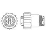
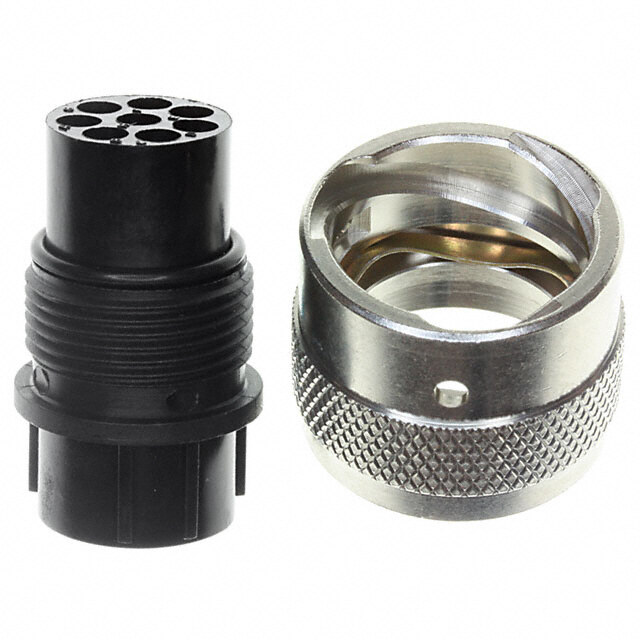
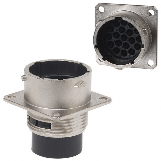
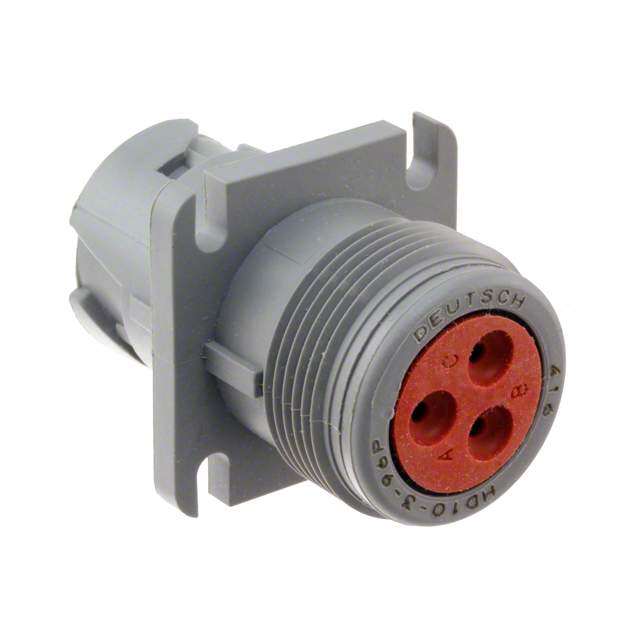
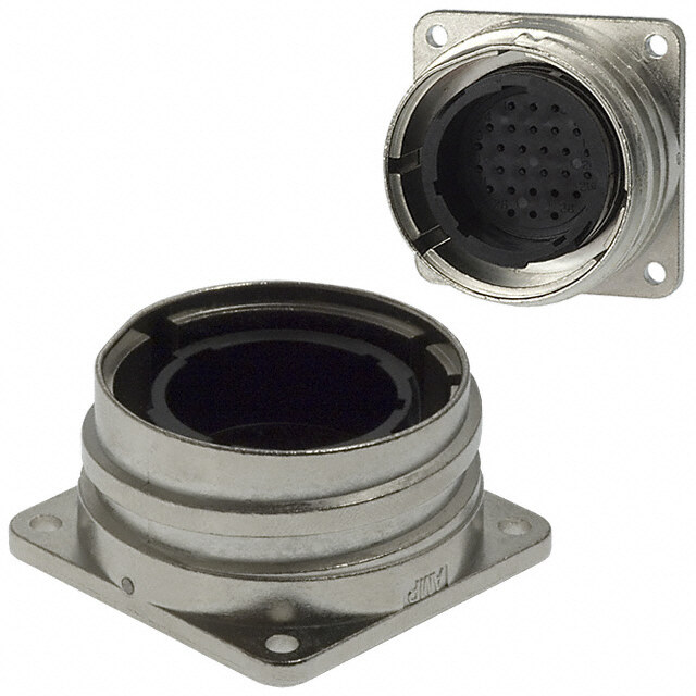
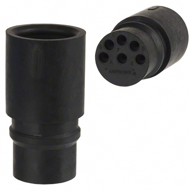
ICGOO电子元器件商城为您提供796094-2由CORCOM/TYCO ELECTRONICS设计生产,在icgoo商城现货销售,并且可以通过原厂、代理商等渠道进行代购。 796094-2价格参考¥68.17-¥75.73。CORCOM/TYCO ELECTRONICS796094-2封装/规格:圆形连接器 - 外壳, 4 Position Circular Connector Plug Housing Free Hanging (In-Line) Coupling Nut。您可以下载796094-2参考资料、Datasheet数据手册功能说明书,资料中有796094-2 详细功能的应用电路图电压和使用方法及教程。
型号为796094-2的TE Connectivity AMP Connectors圆形连接器外壳,主要应用于需要可靠电连接和良好机械保护的工业及自动化设备中。该产品常用于工厂自动化、机械设备、输送系统以及控制柜中,适用于恶劣工业环境,如存在灰尘、湿气或振动的场所。

其坚固设计可确保连接稳定,具备良好的防护等级,适合用于需要频繁插拔或长期稳定运行的场景。此外,该型号也常见于测试设备和仪器仪表中,以提供安全可靠的信号与电源传输。
| 参数 | 数值 |
| 3D型号 | http://www.te.com/commerce/DocumentDelivery/DDEController?Action=srchrtrv&DocNm=796094-2&DocType=Customer+View+Model&DocLang=English |
| 产品目录 | |
| 描述 | CONN PLUG CPC 4POS STD SER 1标准环形连接器 4P PLUG W/O CONTACTS |
| 产品分类 | |
| 品牌 | TE Connectivity |
| 产品手册 | http://www.te.com/catalog/pn/en/796094-2 |
| 产品图片 |
|
| rohs | 符合RoHS无铅 / 符合限制有害物质指令(RoHS)规范要求 |
| 产品系列 | 标准环形连接器,标准环形连接器,TE Connectivity 796094-2CPC 系列 1,AMPSeries 1 |
| 数据手册 | http://www.te.com/commerce/DocumentDelivery/DDEController?Action=srchrtrv&DocNm=796094&DocType=Customer+Drawing&DocLang=English |
| 产品型号 | 796094-2 |
| PCB保持结构 | - |
| RoHS指令信息 | http://www.te.com/commerce/alt/SinglePartSearch.do?PN=796094-2&dest=stmt点击此处下载产品Datasheet |
| 产品种类 | 标准环形连接器 |
| 产品类型 | Housings |
| 位置数量 | 4 |
| 侵入防护 | IP67 - 防尘,防水 |
| 信号位置数 | 4 |
| 其它名称 | 796094-2-ND |
| 包装 | 散装 |
| 匹配样式 | Threaded |
| 反向极性 | Standard |
| 反向编号 | Without |
| 可燃性等级 | - |
| 商标 | TE Connectivity |
| 商标名 | CPC Series 1 |
| 备注 | 不提供触点 |
| 外壳大小 | 11 |
| 外壳尺寸-插件 | 11-4 |
| 外壳尺寸,MIL | - |
| 外壳材料 | Nylon |
| 外壳材料,镀层 | 热塑塑胶 |
| 外壳材质 | - |
| 外壳电镀 | - |
| 外壳类型 | Plug |
| 安装类型 | - |
| 安装角 | Straight |
| 安装风格 | Free Hanging |
| 密封类型 | Wire Entry |
| 工厂包装数量 | 100 |
| 无铅焊接工艺 | Not relevant for lead free process |
| 朝向 | 带标记 |
| 未加载位置 | - |
| 标准包装 | 100 |
| 特性 | - |
| 特色产品 | http://www.digikey.com/product-highlights/cn/zh/te-connectivity-circular-connectors/2464 |
| 电源位置数 | 0 |
| 相关产品 | /product-detail/zh/202237-3/A110854-ND/4127578 |
| 端子尾部电镀 | - |
| 端接柱长度 | - |
| 端接类型 | - |
| 系列 | CPC |
| 紧固类型 | 有螺纹 |
| 经过VDE测试 | No |
| 螺纹大小 | 5/8-24 |
| 触头尺寸 | 16 |
| 触头类型 | 压接 |
| 触点材料 | - |
| 触点电镀 | - |
| 触点电镀厚度 | - |
| 触点类型 | Socket |
| 连接器样式 | Plug |
| 连接器类型 | 母触点插头 |
| 配套产品 | /product-detail/zh/796095-2/796095-2-ND/2258758/product-detail/zh/796096-2/A114492-ND/1245037 |
| 针脚数 | 4 |
| 键控 | - |


.jpg)

.jpg)

- 商务部:美国ITC正式对集成电路等产品启动337调查
- 曝三星4nm工艺存在良率问题 高通将骁龙8 Gen1或转产台积电
- 太阳诱电将投资9.5亿元在常州建新厂生产MLCC 预计2023年完工
- 英特尔发布欧洲新工厂建设计划 深化IDM 2.0 战略
- 台积电先进制程称霸业界 有大客户加持明年业绩稳了
- 达到5530亿美元!SIA预计今年全球半导体销售额将创下新高
- 英特尔拟将自动驾驶子公司Mobileye上市 估值或超500亿美元
- 三星加码芯片和SET,合并消费电子和移动部门,撤换高东真等 CEO
- 三星电子宣布重大人事变动 还合并消费电子和移动部门
- 海关总署:前11个月进口集成电路产品价值2.52万亿元 增长14.8%


PDF Datasheet 数据手册内容提取
RoHS Ready AMP Circular Connectors for Commercial Signal & Power Applications Tyco ElectronicsCorporation Harrisburg, PA tycoelectronics.com 82021-XXX-MS-FP-Rev. 6-07 OG3B
AMP Circular Connectors for Note:All part numbers are RoHS Compliant. Commercial Signal and Power Applications Introduction Product Facts nCertified by MIL-C-5015 Style Circular Miniature CPC Canadian Standards Plastic Connectors (CPC) Connectors nLightweight, all-plastic and Association, R metal-shell connectors Product Facts Product Facts File No. LR 7189 nCPC connectors are UL n Produced under a Quality nIntermateable with Metal-Shell n Compact, high contact density, 94V-0 rated and made of Management System certified sizes 20-14 and environmentally sealed stabilized, heat resistant, self- to ISO 9001 18-10, MIL-C-5015 Style connectors nemMxaetittneagrl-iuasihlsehliln CgP thCe cromnonpelcatsotric n Acuepcrotoinfpi cyrea oqtefu teihss eta. vailable IS O9C0er0tif1ied ncHpolinagnshet iiccmt ohproasucsti rnegs mistaadnet of n UMfosrAemTsEe e-dNx pi-sLitnOi naKgn dMs tsianomic-pkUeentdi vc aeonrnsdtaalcts hthoeursminogpsl amstaicde of UL 94V-0 rated nCertain products meet UL 94V-0 rated material n Two shell sizes—available VDE Standard 062 n Lightweight in 1 to 4 and 5 to 9 position nO-4p0e°rCa ttion g+ 1te0m5°pCerature range: Six connector series for n Lower cost than standard MIL-C- configurations different interconnection 5015 connectors Need more information? nAmvoauilnatb alned i nfr peaen-heal nogr icnhgassis requirements: n Industry accepted Type III+ pin Call Technical Support. configurations nSsiegrnieasl a1n—d Slotawn-dcaurrdre dnetnsity, aonnd r eseolcsk ient sctornipta fcotrsm, afovar ihlaigbhle They are staffed with specialists nQuick connect/disconnect applications using durable volume, low cost, automatic well versed in Tyco Electronics capability with thread assist, Multimate contacts (.062 [1.57] machine terminations, or in products. They can provide: positive detent coupling pin diameter) loose piece form for low nTechnical Support nBpruoitlet-cinti opnin and socket nSapeprileicsa 2ti—onHsi ugshi ndge nSsiiztey vmoaluinmteen, apnrcoeto atynpde r eoprair nnCTeactahlnoigcsal Documents nPcoonlanreizcetodr fhoar lpvreosper mating of 2[10. 0D2M] painnd d 2ia0m DeFt ecro)ntacts (.040 n ISmtapnrdoaverdd MalIiLg-nCm-5e0n1t 5(U.S. nnPAruotdhourcizt eSda mTypcleos Electronics Connectors) prevents mismating Distributor Locations nSpecial connector configurations nSeries 3—Low density, power with other housing insert offer special solder and posted applications with Type XII arrangements contacts, special receptacles contacts capable of carrying up to ©1973, 1975, 1976, 1978, 1981, 1983, 1985, with or without threaded inserts 35 amperes of current n Recognized under the 1989, 1990, 1991, 1992, 1995, 1996, 1999, 2000, Component Program of 2001, 2002, 2004, 2006 and 2007 by Tyco nFull complement of optional nSeries 4—Combination of Underwriters Electronics Corporation.All Rights Reserved. accessories standard and power density Laboratories Inc., AMP, AMPOMATOR, AMP-O-LECTRIC, nRecognized under the aTpyppeli cXaItIi oconn wtaitchts Type III+ and File No. E28476 R ACMERPT-IO-C-MRAIMTIPC, ,C AOMAPX-ITCAOPNE, TMRAOTNEI-CN, -LOK, Component Program of n Certified by POWERBAND, PRO-CRIMPER and TYCO are Underwriters nSeries 5—Power density Canadian Standards trademarks. Laboratories Inc. application with Size 8 screw Association, Komax and TopWin are trademarks of for 250 VAC, rms R machined and precision formed File No. LR 7189 R Komax AG. TETRASEALSis a trademark of or 250 VDC, Service ; contacts ‡ Parker Hannifin Corporation. Series 1 and Series 3 (600 V); nSeries 6—Combination of AIRflex, FLEXAgraff, FLEXAquick, and ROHRflex Series 4 (600 V) and standard and power density are trademarks of Flexa GmbH & Co. Series 2, Series 6 (250 V) application with Type III+ and Other products, logos, and Company names File No. E28476 mentioned herein may be trademarks of their Size 8 contacts respective owners. ‡Select connectors are recognized for 600 volts service. Restriction on the use of certain electrical and electronic Getting the Information nDownloadable Technical Data Hazardous Substances (RoHS) products sold into the EU as of You Need nCustomer Information 1July 2006. At Tyco Electronics, we’re Our comprehensive on-line Presentation ready to support your RoHS Note - For purposes of this RoHS Customer Support Center nMore detailed information requirements. We’ve assessed Catalog, included within the provides a forum to answer regarding the definitions used more than 1.5 million end definition of RoHS Compliant your questions and support above items/components for RoHS are products that are clearly your RoHS needs. A RoHS FAQ compliance, and issued new “Out of Scope” of the RoHS (Frequently Asked Questions) is So whatever your questions part numbers where any Directive such as hand tools available with links to more when it comes to RoHS, we’ve change was required to and other non-electrical detailed information. You can got the answers at eliminate the restricted accessories. Information also submit RoHS questions www.tycoelectronics.com/leadfree materials. regarding RoHS compliance is and receive a response within provided based on reasonable 24 hours during a normal work Part numbers in this catalog are inquiry of our suppliers and week. The Support Center also RoHS Compliant, unless represents our current actual provides: marked otherwise. These knowledge based on the products comply with European nCross-Reference from Non- information provided by our Union Directive 2002/95/EC as compliant to Compliant suppliers. This information is amended 1 January 2006 that Products subject to change. For latest restricts the use of lead, compliance status, refer to our nAbility to browse RoHS mercury, cadmium, hexavalent website referenced at right. Compliant Products in our chromium, PBB, and PBDE in 2 on-line catalog Catalog 82021 Dimensions are in inches and Dimensions are shown for USA: 1-800-522-6752 South America: 55-11-2103-6000 Revised 7-07 millimeters unless otherwise reference purposes only. Canada: 1-905-470-4425 Hong Kong: 852-2735-1628 specified. Values in brackets Specifications subject Mexico: 52-55-1106-0800 Japan: 81-44-844-8013 www.tycoelectronics.com are metric equivalents. to change. C. America: 57-1-254-4444 UK:44-208-420-8341
AMP Circular Connectors for Note:All part numbers are RoHS Compliant. Commercial Signal and Power Applications Table of Contents Introduction...........................................................................2 Contents .............................................................................3 Connector Series and Types .............................................................4, 5 Performance Characteristics...............................................................6 Internal Protection (IP) Codes ..............................................................7 Current Carrying Capabilities ..............................................................8 Example of New Current Rating Format .......................................................9 CPC, Series 1 Cable or Panel Mount Connectors . . . . . . . . . . . . . . . . . . . . . . . . . . . . . . . . . . . . . . . . . . . . . . . . . . . .10, 11 Printed Circuit Board Mount Connectors . . . . . . . . . . . . . . . . . . . . . . . . . . . . . . . . . . . . . . . . . . . . . . .12, 13 Square Flange Receptacles with Round Posted Contacts . . . . . . . . . . . . . . . . . . . . . . . . . . . . . . . . . . . . .13 Square Flange Receptacles with Solder Cup Contacts . . . . . . . . . . . . . . . . . . . . . . . . . . . . . . . . . . . . . . .14 Feed-Thru Connectors . . . . . . . . . . . . . . . . . . . . . . . . . . . . . . . . . . . . . . . . . . . . . . . . . . . . . . . . . . . . . . . .14 Square Flange Receptacles, Right-Angle, Posted . . . . . . . . . . . . . . . . . . . . . . . . . . . . . . . . . . . . . . . .15,16 Contacts, Type III+ (including Lead Free and Enhanced High Current) . . . . . . . . . . . . . . . . . . . . . . . .17-20 Contacts, Type II . . . . . . . . . . . . . . . . . . . . . . . . . . . . . . . . . . . . . . . . . . . . . . . . . . . . . . . . . . . . . . . . . . . . .21 Contacts, Subminiature Coaxial . . . . . . . . . . . . . . . . . . . . . . . . . . . . . . . . . . . . . . . . . . . . . . . . . . . . . .22, 23 Contact Arrangements, Series 1 . . . . . . . . . . . . . . . . . . . . . . . . . . . . . . . . . . . . . . . . . . . . . . . . . . . . . . . . .24 Component Dimensions, Series 1 . . . . . . . . . . . . . . . . . . . . . . . . . . . . . . . . . . . . . . . . . . . . . . . . . . . . . . . .25 CPC, Series 2 Cable or Panel Mount Connectors . . . . . . . . . . . . . . . . . . . . . . . . . . . . . . . . . . . . . . . . . . . . . . . . . . . . . . .26 Printed Circuit Board Mount Connectors . . . . . . . . . . . . . . . . . . . . . . . . . . . . . . . . . . . . . . . . . . . . . . . . . .27 Square Flange Feed-Thru Receptacles . . . . . . . . . . . . . . . . . . . . . . . . . . . . . . . . . . . . . . . . . . . . . . . . . . .28 Contacts,Size 20 DF Crimp . . . . . . . . . . . . . . . . . . . . . . . . . . . . . . . . . . . . . . . . . . . . . . . . . . . . . . . . . . . .29 Contacts, Size 20 DM Crimp and 20 DF Solder . . . . . . . . . . . . . . . . . . . . . . . . . . . . . . . . . . . . . . . . . . . . .30 Contact Arrangements, Series 2 . . . . . . . . . . . . . . . . . . . . . . . . . . . . . . . . . . . . . . . . . . . . . . . . . . . . . . . . .31 Component Dimensions, Series 2 . . . . . . . . . . . . . . . . . . . . . . . . . . . . . . . . . . . . . . . . . . . . . . . . . . . . . . . .32 CPC, Series 3 Plugs and Receptacles, Series 3 . . . . . . . . . . . . . . . . . . . . . . . . . . . . . . . . . . . . . . . . . . . . . . . . . . . . . . . .33 Power Contacts, Type XII . . . . . . . . . . . . . . . . . . . . . . . . . . . . . . . . . . . . . . . . . . . . . . . . . . . . . . . . . . .34, 35 Contact Arrangements, Series 3 . . . . . . . . . . . . . . . . . . . . . . . . . . . . . . . . . . . . . . . . . . . . . . . . . . . . . . . . .35 Component Dimensions, Series 3 . . . . . . . . . . . . . . . . . . . . . . . . . . . . . . . . . . . . . . . . . . . . . . . . . . . . . . . .36 CPC, Series 4 Plugs and Receptacles, Series 4 . . . . . . . . . . . . . . . . . . . . . . . . . . . . . . . . . . . . . . . . . . . . . . . . . . . . . . . .37 Contact Arrangements, Series 4 . . . . . . . . . . . . . . . . . . . . . . . . . . . . . . . . . . . . . . . . . . . . . . . . . . . . . . . . .38 CPC Connector Accessories Cable Clamps . . . . . . . . . . . . . . . . . . . . . . . . . . . . . . . . . . . . . . . . . . . . . . . . . . . . . . . . . . . . . . . . . . . .38, 39 Back-Shell Extender and Panel Mount Flanges . . . . . . . . . . . . . . . . . . . . . . . . . . . . . . . . . . . . . . . . . . . . .40 Flexible Cable Boots and Internal Cable Grips . . . . . . . . . . . . . . . . . . . . . . . . . . . . . . . . . . . . . . . . . . . . . .41 Keying Plugs . . . . . . . . . . . . . . . . . . . . . . . . . . . . . . . . . . . . . . . . . . . . . . . . . . . . . . . . . . . . . . . . . . . . . . . .42 Sealed CPC Connectors One-Piece Sealed CPC . . . . . . . . . . . . . . . . . . . . . . . . . . . . . . . . . . . . . . . . . . . . . . . . . . . . . . . . . . . . .43-45 Two-Piece Sealed CPC . . . . . . . . . . . . . . . . . . . . . . . . . . . . . . . . . . . . . . . . . . . . . . . . . . . . . . . . . . . . . . . .46 .125 POWERBAND Contacts . . . . . . . . . . . . . . . . . . . . . . . . . . . . . . . . . . . . . . . . . . . . . . . . . . . . . . . . . .47 Connectors, Series 5 and Wire Entry Seals . . . . . . . . . . . . . . . . . . . . . . . . . . . . . . . . . . . . . . . . . . . . . . .48 Connectors, Series 6 and Wire Entry Seals . . . . . . . . . . . . . . . . . . . . . . . . . . . . . . . . . . . . . . . . . . . . . . .49 Connectors, Special Series 1 . . . . . . . . . . . . . . . . . . . . . . . . . . . . . . . . . . . . . . . . . . . . . . . . . . . . . . . . . .50 Wire Entry Seal Kits and Flange Seals . . . . . . . . . . . . . . . . . . . . . . . . . . . . . . . . . . . . . . . . . . . . . . . . . . .51 CPC Connector Sealing Accessories Sealing Caps and Cable Entry Seals . . . . . . . . . . . . . . . . . . . . . . . . . . . . . . . . . . . . . . . . . . . . . . . . . . . . .52 Jacketed Cable Seals and Rubber Boot . . . . . . . . . . . . . . . . . . . . . . . . . . . . . . . . . . . . . . . . . . . . . . . . . . .53 Flexible Cable Protection System . . . . . . . . . . . . . . . . . . . . . . . . . . . . . . . . . . . . . . . . . . . . . . . . . . . . . . . .54 MIL-C-5015 Style Circular Plastic Connectors Introduction . . . . . . . . . . . . . . . . . . . . . . . . . . . . . . . . . . . . . . . . . . . . . . . . . . . . . . . . . . . . . . . . . . . . . . . . .55 Connectors, Plugs and Receptacles—Shell Size 20-14 . . . . . . . . . . . . . . . . . . . . . . . . . . . . . . . . . . . . . . .56 Connectors, Plugs and Receptacles—Shell Size 18-10, and Type III+ Contacts . . . . . . . . . . . . . . . . . . .57 Metal-Shell Circular Plastic Connectors Introduction . . . . . . . . . . . . . . . . . . . . . . . . . . . . . . . . . . . . . . . . . . . . . . . . . . . . . . . . . . . . . . . . . . . . . . . . .58 Receptacles and Plugs, Series 1, Standard Sex . . . . . . . . . . . . . . . . . . . . . . . . . . . . . . . . . . . . . . . . . . . .59 Receptacles and Plugs, Series 1, Reverse Sex . . . . . . . . . . . . . . . . . . . . . . . . . . . . . . . . . . . . . . . . . . . . .60 Contact Arrangements, Series 1 . . . . . . . . . . . . . . . . . . . . . . . . . . . . . . . . . . . . . . . . . . . . . . . . . . . . . . . . .61 Receptacles and Plugs, Series 2, Standard Sex . . . . . . . . . . . . . . . . . . . . . . . . . . . . . . . . . . . . . . . . . . . .62 Receptacles and Plugs, Series 2, Reverse Sex . . . . . . . . . . . . . . . . . . . . . . . . . . . . . . . . . . . . . . . . . . . . .63 Contact Arrangements, Series 2 . . . . . . . . . . . . . . . . . . . . . . . . . . . . . . . . . . . . . . . . . . . . . . . . . . . . . . . . .64 Receptacles and Plugs, Series 3, Standard Sex . . . . . . . . . . . . . . . . . . . . . . . . . . . . . . . . . . . . . . . . . . . .65 Receptacles and Plugs, Series 3, Reverse Sex . . . . . . . . . . . . . . . . . . . . . . . . . . . . . . . . . . . . . . . . . . . . .66 Contact Arrangements, Series 3 . . . . . . . . . . . . . . . . . . . . . . . . . . . . . . . . . . . . . . . . . . . . . . . . . . . . . . . . .67 Receptacles and Plugs, Series 4, Standard Sex . . . . . . . . . . . . . . . . . . . . . . . . . . . . . . . . . . . . . . . . . . . .68 Contact Arrangements, Series 4 . . . . . . . . . . . . . . . . . . . . . . . . . . . . . . . . . . . . . . . . . . . . . . . . . . . . . . . . .69 Component Dimensions, Series 1, 2, 3 and 4 . . . . . . . . . . . . . . . . . . . . . . . . . . . . . . . . . . . . . . . . . . . . . . .70 Metal-Shell CPC Connector Accessories Cable Clamps, Cable Entry Seals and Protective Cap Assemblies . . . . . . . . . . . . . . . . . . . . . . . .38, 39, 71 Miniature CPC Connectors Introduction . . . . . . . . . . . . . . . . . . . . . . . . . . . . . . . . . . . . . . . . . . . . . . . . . . . . . . . . . . . . . . . . . . . . . . . . .72 Plugs, Receptacles and Contacts . . . . . . . . . . . . . . . . . . . . . . . . . . . . . . . . . . . . . . . . . . . . . . . . . . . . .73-75 Accessories . . . . . . . . . . . . . . . . . . . . . . . . . . . . . . . . . . . . . . . . . . . . . . . . . . . . . . . . . . . . . . . . . . . . . . . . .75 Application Tooling..................................................................76-79 Technical Documents ...................................................................80 Part Number Index Products . . . . . . . . . . . . . . . . . . . . . . . . . . . . . . . . . . . . . . . . . . . . . . . . . . . . . . . . . . . . . . . . . . . . . . . . . . . . .81, 82 Tooling . . . . . . . . . . . . . . . . . . . . . . . . . . . . . . . . . . . . . . . . . . . . . . . . . . . . . . . . . . . . . . . . . . . . . . . . . . . . . . . . . .83 Part Number Cross Reference (Non-Compliant to RoHS Compliant) . . . . . . . . . . . . . . . . . . . . . . . . . . . . . . . . . .83 Global Contacts ............................................................................84 3 Catalog 82021 Dimensions are in inches and Dimensions are shown for USA: 1-800-522-6752 South America: 55-11-2103-6000 Revised 7-07 millimeters unless otherwise reference purposes only. Canada: 1-905-470-4425 Hong Kong: 852-2735-1628 specified. Values in brackets Specifications subject Mexico: 52-55-1106-0800 Japan: 81-44-844-8013 www.tycoelectronics.com are metric equivalents. to change. C. America: 57-1-254-4444 UK:44-208-420-8341
AMP Circular Connectors for Note:All part numbers are RoHS Compliant. Commercial Signal and Power Applications Connector Series and Types Series 1—Size 16 Contacts 1 3 Series 1 connectors permit subminiature coaxial Type III solder contacts the use of multiple combina- contacts, interchangeable in and posted contacts for pc 4 7 tions of signal and coaxial the same Multimate contact board applications are also circuits in the same housing cavity. Type III+ contacts available. Many connector 6 11 byaccepting durable (.062 [1.57] pin diameter) arrangements offer both Multimate contacts. These are capable of carrying a standard and reverse sex pin and socket contacts maximum of 13 amperes contact loading—from 4 12 14 include Type III+ and when crimped in wire. thru 37 positions. Series 2—Size 20 Contacts 1 3 Series 2 connectors accept for wrap-type and pc board 4 8 Size 20 DF (precision applications. Maximum 9 14 formed) and Size 20 DM current carrying capability (screw-machined) pin and is 7.5 amperes. Many 15 20 socket contacts with a .040 connector arrangements [1.02] pin diameter, Size 20 offer both standard and 21 25 DF contacts are available in reverse sex contact crimp and solder versions, loading—from 8 thru 63 26 28 as well as a posted version positions. Series 3—Power Contacts Series 3 connectors accept 10 AWG [1.4 to 5 mm2]. 1 2 Type XII power contacts Two connector sizes are which can carry up to 25 available in both standard amps per contact. These and reverse sex connector 3 5 contacts will accommodate arrangements 3and 7 awire size range of 16 to positions. 6 7 Series 4—Combination 1 Size 16 and Power Contacts 2 3 Series 4 connectors accept power circuit capabilities of Size 16 Multimate and Series 3 connectors. 7 4 5 10 Type XII power contacts, Available in two connector 6 8 combining the signal and sizes offering power mixing coaxial circuit capabilities of combinations totaling 16 11 13 Series 1connectors with the and 22 positions. 14 16 15 4 Catalog 82021 Dimensions are in inches and Dimensions are shown for USA: 1-800-522-6752 South America: 55-11-2103-6000 Revised 7-07 millimeters unless otherwise reference purposes only. Canada: 1-905-470-4425 Hong Kong: 852-2735-1628 specified. Values in brackets Specifications subject Mexico: 52-55-1106-0800 Japan: 81-44-844-8013 www.tycoelectronics.com are metric equivalents. to change. C. America: 57-1-254-4444 UK:44-208-420-8341
AMP Circular Connectors for Note:All part numbers are RoHS Compliant. Commercial Signal and Power Applications Connector Series and Types(Continued) Series 5—Power Contacts 11 22 .125 POWERBAND Series 5 connectors combine performance of the best Mil Rated at 600 VAC or VDC, the revolutionary Spec Size 8 screw-machined 45 amperes maximum in performance of the new contacts with the economy asingle contact, the AMP POWERBAND and productivity of strip-fed, connectors are available in Contact, high current precision formed contacts. free-hanging and panel- 33 contact in configurations mount applications—one Series 5 connectors are similar to the Series 3 connector configuration environmentally sealable to connectors. AMP containing three .125 meet IEC IP 65 and IP 67 POWERBAND contacts POWERBAND contacts. specifications. offer the electrical Series 6—Combination, 2 Size 16 and .125 1 3 POWERBAND Contacts This combination of power Series 6 combines the high and signal contacts is current and environmental offered in one connector sealing capability of configuration containing Series 5, POWERBAND two .125 POWERBAND 8 9 10 contacts, and the reliability contacts and eight of signal carrying, low Type III+ signal pin and current Type III+ contacts. socket contacts. MIL-C-5015 Style—Size 16 Contacts This new addition to the AMP and lower cost than existing economies of crimp Circular Plastic Connector Line metal-shell connectors. In Type III+ pin and socket is specifically designed to be addition the connector design contacts in reel-mounted, intermateable with Metal- prevents mismating when strip-form for high volume Shell size 20-14 and 18-10, used with other insert automatic machine MIL-C-5015 Style connector arrangements. As part of termination, as well as in loose systems.The high impact the AMP Multimate family of piece-form for low volume, resistant plastic housing offers connectors, the MIL-C-5015 prototype or maintenance and the advantages of light weight style connector offers the repair. Metal-Shell, Circular Plastic Connectors Metal-Shell CPC connectors shell sizes 14, 22 and 28, consist of a black and in two basic thermoplastic insert in a configurations consisting nickel-plated, zinc alloy of plugs and square shell. These connectors flange receptacles. are currently available in Miniature CPC Connectors These compact connectors Two shell sizes (8 or 11) are Featuring high contact accept existing Mini- available, accommodating density and IP67 sealing, UniversalMATE-N-LOK pin from 1 to 4 and 5 to 9 these durable connectors and socket contacts, positions. are well suited for many 30-18 AWG [.05-.8 mm2]. wire-to-wire, wire-to-board, and wire-to-panel applications. 5 Catalog 82021 Dimensions are in inches and Dimensions are shown for USA: 1-800-522-6752 South America: 55-11-2103-6000 Revised 7-07 millimeters unless otherwise reference purposes only. Canada: 1-905-470-4425 Hong Kong: 852-2735-1628 specified. Values in brackets Specifications subject Mexico: 52-55-1106-0800 Japan: 81-44-844-8013 www.tycoelectronics.com are metric equivalents. to change. C. America: 57-1-254-4444 UK:44-208-420-8341
AMP Circular Connectors for Note:All part numbers are RoHS Compliant. Commercial Signal and Power Applications Performance Characteristics — CPC and Metal-Shell CPC Connectors More information on the Test Description Procedure Requirements performance of AMP CPC Maintenance Contacts removed and No damage to contacts and metal-shell CPC Aging reinserted 10 times using or housings. Contact connectors is available by applicable tools retention maintained requesting the following AMP Product Specifications: Contact Retention Axial load applied to Contacts remain in 108-10024–– contact to displace to the place when subjected to CPC Connectors rear of the connector a minimum 10 lb. load* 108-10037–– Dielectric Withstanding Connectors subjected to No breakdown or Type XII Contacts Voltage (MIL-STD-1344, 1500 volts rms at sea flashover 108-10020–– Method 3001) level Size 20 DM and 20 DF Contacts Thermal Shock Connectors subjected to No damage 108-10040–– five cycles of temperature Metal-Shell CPC change (-55°C and +125°C) Connectors Vibration Connectors vibrated No damage or loosening of 108-10042–– (MIL-STD-202, (wired and mated). parts. No interruption Type III+ Contacts Method 204, Contacts wired in series of electrical continuity 108-1579–– Test Condition B) with 100 milliamperes longer than 10 microseconds Sealed CPC Connectors flowing during the test with Removeable Contacts Physical Shock Connectors shocked No damage or loosening (MIL-STD-202, 50 G (wired and mated). of parts. No interruption of Method 213A, Contacts wired in series electrical continuity longer Test Condition A) with 100 milliamperes than 10 microseconds flowing during the test Durability Connectors mated and No wear through unmated 25 times with tin damage to plating plated contacts and 500 times with gold plated contacts Corrosion (Salt Spray) Mated connectors No damage (MIL-STD-202, Method 101, subjected to 5% salt Test Condition B) spray for 48 hours Protection Against a.Test wire is pushed a. Must not touch live parts Solids into mated connectors b. No dust deposits b. Mated connectors observed on mating subjected to circulating surfaces talcum powder Protection Against Water is projected through No water deposits shall Water jets against mated be observed on mating connector from any direction surfaces of contacts and then temporarily or housings immersed in water Temperature Life Mated connectors No damage subjected to a temperature of +125°C for 200 hours Insulation Resistance Measurement made 5000 megohms (MIL-STD-1344, between adjacent contacts minimum ambient Method 3003) with connector mated temperature Humidity Mated connectors Minimum insulation (MIL-STD-202, Method 103, subjected to 10 days resistance of Test Condition B) moisture test 100 megohms *For size 16 contacts. Size 8 contacts 25 lb. load, min. 6 Catalog 82021 Dimensions are in inches and Dimensions are shown for USA: 1-800-522-6752 South America: 55-11-2103-6000 Revised 7-07 millimeters unless otherwise reference purposes only. Canada: 1-905-470-4425 Hong Kong: 852-2735-1628 specified. Values in brackets Specifications subject Mexico: 52-55-1106-0800 Japan: 81-44-844-8013 www.tycoelectronics.com are metric equivalents. to change. C. America: 57-1-254-4444 UK:44-208-420-8341
AMP Circular Connectors for Note:All part numbers are RoHS Compliant. Commercial Signal and Power Applications Levels of Protection for Electric Operating Material According to IEC 60529 and IEC 60947, Appendix C Environmentally Protected Internal Protection (IP) Circular Plastic Connectors, Definition: for Mated CPC Connectors nPer IEC 60947, Appendix C— Utilizing Peripheral Seals Pertains to low voltage switchgear and and either Wire Entry Seals control gear. (for Discrete Wire nPer IEC 60529—Pertains to degrees of protection provided by enclosures Applications) or Heat (IP code). Shrink Boots(for Jacketed Cable Applications). Available are Various Sample Designation: Sizes, Series 1, 5 and 6. (Where x is a numeral value), i.e. IP 65 IP Codes IP X X 1 2 Index Letter Degree of Protection Degree of Protection against ingress of solid against ingress of water foreign objects Degree of Protection against ingress of Degree of Protection against Protection, X1 solid foreign objects Protection, X2 ingress of water No Protection 0 No Protection Protection against objects Vertical Dripping— 1 >50mm diameter— 1 Protection against vertical including inadvertently drops of water touched by hands Dripping <15°— Protection against objects Protection against dripping 2 2 >12.5mm—including fingers water when the enclosure is tilted 15°from vertical Protection against objects Spraying at an angle up 3 3 >2.5mm diameter including tools to 60°from vertical Protection against objects Splashing—Protection 4 >1.0mm diameter— 4 against water splashed including grains from any direction Jetting—Protection against Protection against ingress 5 5 water stream out of a nozzle, of solid foreign bodies from any direction Powerful Jetting—Protection against temporary flooding due 6 Protection against ingress of dust 6 to powerful jet streams out of a nozzle from any direction Temporary immersion—Protection 7 against temporary immersion 7 Catalog 82021 Dimensions are in inches and Dimensions are shown for USA: 1-800-522-6752 South America: 55-11-2103-6000 Revised 7-07 millimeters unless otherwise reference purposes only. Canada: 1-905-470-4425 Hong Kong: 852-2735-1628 specified. Values in brackets Specifications subject Mexico: 52-55-1106-0800 Japan: 81-44-844-8013 www.tycoelectronics.com are metric equivalents. to change. C. America: 57-1-254-4444 UK:44-208-420-8341
AMP Circular Connectors for Note:All part numbers are RoHS Compliant. Commercial Signal and Power Applications Current Carrying Capabilities The total current capacity of CONTACT CURRENT GUIDE Maximum Current (Amperes) for Largest Wire Size each contact in a given 75 connector is dependent upon Type XII Upgrade the heat rise resulting from the combination of electrical loads 60 Size 8 Upgrade 60 of the contacts in the connector 56 arrangement and the maximum 50 .125 POWERBAND Contact ambient temperature in which the connector will be operating. 45 45 Size 8 Caution must be taken so that this combination of conditions 35 Type XII does not cause the internal 30 Type I, Type II/III+ temperature of the connector to 23 Upgrade exceed the maximum operating Type III+, Type II, temperature of the housing Type III+Posted material. Several variables 15 13 11.85 which must be considered Size 20 Upgrade 7.5 when determining this maximum current capability for 20 DF 0 your application are: nWire Size—Larger wire will nConnector Size—In general, nCurrent Load Distribution— nAmbient Temperature—With carry more current since it with more circuits in a Spreading those lines with higher ambient temperatures, has less internal resistance connector, less current per greater current loads through- less current can be carried. to current flow and generates contact can be carried. out the connector, particularly less heat. The wire also around the outer perimeter, conducts heat away from the will enhance heat dissipation. connector. Current Rating Verification design-life (EODL) conditions. Temperature loading density. A connector Can a contact rated at 10 amps Practical current-carrying capac- containing 50% current-carrying One other factor influencing carry 10 amps? ity is not an absolute, but an contacts will permit higher current levels is the maximum application-dependent condition. currents (per contact) than a Maybe yes, but probably not. operating temperature, for The reason lies in the test New Method Simplifies Ratings example, 105°C. If the appli- connector will at 75% loading. The loading percentage assumes conditions used to rate the To help the designer set the cation has a high ambient an even distribution of contacts contact. If these conditions do appropriate current level, Tyco temperature (over 75°C) the within the housing. If all 10 not adequately reflect the appli- Electronics has developed a contact’s T-rise is limited by contacts are grouped together in cation conditions, the actual method of specifying current- the maximum operating one section of a 20-position allowable current levels may be carrying capacity. This method temperature. For example, an connector, the loading density lower than specified levels. For takes into account the various application temperature of may approach 100%. einxcalumdpinleg, mTyacnoy Emleacnturofancictus,r eterss,t aepncpelic cautirorenn fta rcattoinrsg .that influ- 9to0 °1C5° lCim. iStsin tchee ccuornrteanctt T-rise The Importance of EODL a single contact in air. This produces heat (the I2R law), the As stated, T-rise in a contact gives an accurate measure of The method can be summarized current must be lowered to depends on both resistance and the basic current-carrying as follows: limit the T-rise. current. As it ages, a contact’s capacity of the contact. Use the nThe contact is aged to EODL A contact’s T-rise depends not resistance will increase. The contact alone in air and it can conditions by durability only on its I2R Joule heating, but contact designer will specify a certainly carry 10 ampere. Use cycling, thermal cycling, and also on its ability to dissipate maximum resistance for the it in a multi-position connector environmental exposure. the heat. Consider a contact in contact, this level is the end-of- surrounded by other current- nThe contact’s resistance a multi-contact housing. Joule design-life resistance. Before carrying contacts or in high stability is verified. heating in multiple contacts will the contact is tested for current, ambient temperatures, and the raise the local ambient temper- Tyco Electronics subjects it to a contact should carry less nThe current necessary to ature. Since the contact will not sequence of tests that exercises current. produce the specified tempera- be able to dissipate its own the major failure mechanisms ture rise is measured. This Similarly, as the contact ages T-rise is usually 30°C. heat as well by convection, the and thereby simulates EODL and stress relaxation, environ- maximum T-rise will be realized conditions. Conditioning mental cycling, and other nA rating factor is determined at a lower current level. Conse- includes mating cycling, indus- degradation factors take their to allow derating of multiple quently, the allowable current trial mixed-flowing gases, toll, the contact’s current- contacts in the same housing level must be lower to maintain humidity and temperature carrying capacity decreases. and for different conductor an acceptable T-rise. cycling, and vibration to A prudent design must set sizes. For a given connector, the sequentially introduce wear, current levels for such end-of- current level will be set by the corrosion, stress relaxation, and mechanical disturbance. 8 Catalog 82021 Dimensions are in inches and Dimensions are shown for USA: 1-800-522-6752 South America: 55-11-2103-6000 Revised 7-07 millimeters unless otherwise reference purposes only. Canada: 1-905-470-4425 Hong Kong: 852-2735-1628 specified. Values in brackets Specifications subject Mexico: 52-55-1106-0800 Japan: 81-44-844-8013 www.tycoelectronics.com are metric equivalents. to change. C. America: 57-1-254-4444 UK:44-208-420-8341
AMP Circular Connectors for Note:All part numbers are RoHS Compliant. Commercial Signal and Power Applications Presentation — An Example* Current Rating The presentation of current- of connectors and their accept- Figure 1 carrying capacity in AMP able contacts. Once you have 15(cid:9) (cid:13) product specifications includes selected the wire size, current- two parts: carrying capacity need, Single Contact(cid:13) 18 AWG number of positions required, nFirst, a base curve showing and the type of contacts s) cau srirnegnlte l ecvireclus itv aenrsdu sth Te- rlaisreg efosrt nceoendneecdt oinr ,y roeufer rc thoo tihcies omfatrix 10(cid:9)mpere (cid:13) wire size (See figure 1). This A rceuprrreenset nctasp tahcei tmy aoxf itmheum fiso ra ac cqeupictakb loleo kin a at egxivaecntly what ating ( connector type. R contact. The curve is usually 5 nt fthlaetn u dpr otop s75o°fCf. Uamp btoie n7t5 a°Cnd, the *Note:Data is nottypical of a Curre 30°C T-rise limits the amount specific CPC connector configu- of current, and above 75°C ration. For specific current the current must be reduced 0(cid:9) (cid:13) rating information based on % 0(cid:9) 10(cid:9) (cid:13)20(cid:9) (cid:13) 30(cid:9) (cid:13) 40(cid:9) (cid:13) 50(cid:9) (cid:13) 60(cid:9) (cid:13) 70(cid:9) (cid:13) 80(cid:9) (cid:13) 90(cid:9) (cid:13)100(cid:9) (cid:13) (cid:13) to keep the combination of connector loading, contact Ambient Temperature (°C) ambient temperature and Tyco Electronics. Graph shows the relationship between base current, ambient T-rise from exceeding the temperature, and contact T-rise. maximum operating tempera- To demonstrate the method of ture of 105°C. specifying current, consider the following application conditions; nNext are rating factors, a an ambient temperature of 65°C, table of multipliers to account a 50% loading of contacts in AWG for connector loading and for the housing, and 20 AWG smaller wire sizes (See figure 2). [0.6mm2] wire. The designer first determines 18 20 22 24 26 the base current for the nFrom Figure 1, the base ambient conditions of the current rating is 14 ampere application; then multiplies with 18 AWG [0.8mm2] wire. Single 1 .83 .69 .59 .50 this base current by the rating nFigure 2, the rating factor for factors to find the current 50% loading and 20 AWG level for the application’s [0.6mm2] wire is 0.68. loading factor and wire size. 30% .97 .80 .66 .57 .49 nThe specific rating for this application is the product of g Practical Values n The current-rating method tfahcet obra: se rating and the rating oadi 50% .83 .68 .57 .48 .42 L gives designers practical 14 x 0.68 = 9.5 ampere % values applicable to their appli- cations. While the specified nEach of the contacts can 70% .65 .53 .45 .38 .33 carry 9.5 ampere. current levels for a contact may be lower than for other testing nHowever, if the ambient temper- methods, they are more practi- ature is 80°C the allowable 100% .55 .45 .38 .32 .28 cal and simplify the system T-rise becomes 25°C. The base design process. current must be lowered to 12.8 ampere so that the 105°C “Spec-manship” is replaced maximum operating tempera- by a realistic assessment of the current-carrying capacity of a ture is not exceeded. The Figure 2 contact under varying condi- current rating then becomes: Rating factors allow the base current to be adjusted for various tions of temperature, connector 12.8 x 0.68 = 8.7 ampere. connector loading and wire sizes. loading, and wire size. Specific current-carrying data based on EOL and % loading is Contact Selector Chart available from Tyco Electronics. Please contact your local Connector Posted Sub-Mini POWERBAND 20 DF Type I Type II Type III+ Type XII Tyco ElectronicsSales Engineer Type Type III+ Coax Contacts or call Tyco Electronics. CPCSeries 1 4 4 4 4 CPC Series 2 4 CPC Series 3 4 Connector/Contact Acceptability CPC Series 4 4 4 4 4 As previously stated, choosing CPC Series 5 4 the correct connector/contact CPC Series 6 4 4 4 4 combination is fundamental CPC 5015 4 to the successful function of CMC Series 1 4 4 4 4 all connectors. The Selector CMC Series 2 4 Chart shown at right, is CMC Series 3 4 designed to simplify your choice CMC Series 4 4 4 4 4 9 Catalog 82021 Dimensions are in inches and Dimensions are shown for USA: 1-800-522-6752 South America: 55-11-2103-6000 Revised 7-07 millimeters unless otherwise reference purposes only. Canada: 1-905-470-4425 Hong Kong: 852-2735-1628 specified. Values in brackets Specifications subject Mexico: 52-55-1106-0800 Japan: 81-44-844-8013 www.tycoelectronics.com are metric equivalents. to change. C. America: 57-1-254-4444 UK:44-208-420-8341
AMP Circular Connectors for Note:All part numbers are RoHS Compliant. Commercial Signal and Power Applications Circular Plastic Connectors, Size 1 CPC Connectors, Series 1 Square Flange Receptacle *G±[±.002.654] for Cable or Panel Mount *Panel Thk. *F±[±.001.205] *JDia. (Accepts Type III+, High- [.31.2158] Max. Current Power, Type II and Subminiature Coax Contacts) PCs1 *D±[±.001.205] M*aEx. *F±[±.001.205] Crie *H +–[+..00000.1078]Dia. e S *A *Thread Size Max. (See chart) Panel Cutout *B±[±.001.358] *C±[±.001.205] Free-Hanging Receptacle *A Listed part numbers are for Max. connectors only; contacts *B±[±.001.358] must be ordered separately. *C±[±.001.205] Material Housing—Thermoplastic, 94V-0 rated, *D ±[±.001.205] *EMax. *LMax. black *Note: See page 25 for callout dimensions Related Product Data *Thread Size *K (See chart) Max. Contacts—Pages 17-23 Plug Contact Arrangement—Page 24 *MMax. Component Dimensions—Page 25* Accessories—Pages 38-42, 52-54 Performance Characteristics— *NMax. Page 6 Application Tooling—Pages 76-79 Technical Documents—Page 80 *Thread Size (See chart) Standard Sex Connectors (Receptacles accept pin contacts, Plugs accept socket contacts) Replacement Coupling Rings Arrangement Square Flange Receptacle Shell Size Part No. SSihzeel l P o Nsoit.i oonf s Keying WithIn Tsherrtesa1ded WithH Mooleusnting FRreeec-eHpatnagcilneg Plug 11 213811-1 11-4 A 208130-1 206061-1 206153-1 206060-1 13 213813-1 13-9 A 208131-1 206705-1 206705-2 206708-1 17 213810-1 A 206036-8 206036-1 206036-3 206037-1 23 213812-1 17-16 B — 213862-1 — 213849-1 A 211839-1 206838-1 206838-2 206837-1 23-24 B — 213866-1 — 213851-1 Keying A 787610-1 206151-1 206151-2 206150-1 23-37 B — 213860-1 — 213848-1 Molded-in keying in two configurations: 1Four 4-40 threaded inserts per receptacle. A—Standard Configuration: 5 Keys Reverse Sex Connectors (Receptacles accept socket contacts, Plugs accept pin contacts) Arrangement Square Flange Receptacle Shell No. of Keying With Threaded With Mounting FRreeec-eHpatnagcilneg Plug B—Optional Configuration: 4 Keys to Size Positions Inserts1 Holes prevent mismating of standard and 11-4 A 211102-1 206430-1 206430-2 206429-1 reverse sex. A 211103-1 206043-1 206043-3 206044-1 17-14 B — 796437-2 — 796449-1 A 206306-5 206306-1 206306-2 206305-1 23-37 B — 213864-1 — 213850-1 1Four 4-40 threaded inserts per receptacle. Key Style “A” is the Standard 5 Locating Key arrangement. Key Style “B” is the 4 Locating Key arrangement. 10 Catalog 82021 Dimensions are in inches and Dimensions are shown for USA: 1-800-522-6752 South America: 55-11-2103-6000 Revised 7-07 millimeters unless otherwise reference purposes only. Canada: 1-905-470-4425 Hong Kong: 852-2735-1628 specified. Values in brackets Specifications subject Mexico: 52-55-1106-0800 Japan: 81-44-844-8013 www.tycoelectronics.com are metric equivalents. to change. C. America: 57-1-254-4444 UK:44-208-420-8341
AMP Circular Connectors for Note:All part numbers are RoHS Compliant. Commercial Signal and Power Applications Circular Plastic Connectors, Series 1, VDE Tested CPC Connectors, Series 1, Square Flange Receptacle for Cable or Panel Mount *G±[±.002.654] (Accepts Type III+, High- *Panel Thk. *F±[±.001.205] *JDia. Current Power, Type II and [.31.2158] Max. Subminiature Coax Contacts) *D±[±.001.205] *EMax. *F±[±.001.205] SeCP *H +–[+..00000.1078]Dia. riesC 1 *A *Thread Size Max. (See chart) Panel Cutout *B±[±.001.358] *C±[±.001.205] Free-Hanging Receptacle nDesigned to meet requirements of VDE as *A Max. shown in DIN *B±[±.001.358] Specification 57627 *C±[±.001.205] nRecognized under the Component Program of Underwriters Laboratories Inc. *D±[±.001.205] *EMax. *LMax. for 600 VAC and *Note: 600VDC service, See page 25 for callout dimensions File No. E28476 R *Thread Size *K (See chart) Max. nCertified by Canadian Standards Plug Association, R File No. LR 7189 *MMax. Listed part numbers are for connectors only; contacts must be ordered separately. *NMax. Material Housing—Thermoplastic, 94V-0 rated, *Thread Size black (See chart) Standard Sex Connectors (Receptacles accept pin contacts, Plugs accept socket contacts) Related Product Data Arrangement Square Flange Receptacle Shell No. of Keying With Threaded With Mounting Plug Contacts—Pages 17-23 Size Positions Inserts1 Holes Contact Arrangement—Page 24 13-7 A 211401-4 211401-1 211399-1 Component Dimensions—Page 25* 17-9 A 211767-2 211767-1 211766-1 A 211771-2 211771-1 211770-2 Accessories—Pages 38-42, 52-54 23-19 B — 213870-1 213853-1 Performance Characteristics— 1Four 4-40 threaded inserts per receptacle. Page 6 Application Tooling—Pages 76-79 Reverse Sex Connectors (Receptacles accept socket contacts, Plugs accept pin contacts) Technical Documents—Page 80 Arrangement Square Flange Receptacle Free-Hanging Shell No. of Keying With Threaded With Mounting Receptacle Plug Replacement Coupling Rings Size Positions Inserts1 Holes 13-7 A 211398-4 211398-1 211398-2 211400-1 Shell Size Part No. A — 211769-1 211769-3 211768-1 17-9 13 213813-1 B — 796439-2 — 796450-1 17 213810-1 A — 211773-1 — 211772-1 23-19 23 213812-1 B — 213868-1 — 213852-1 1Four 4-40 threaded inserts per receptacle. Keying Key Style “A” is the Standard 5 Locating Key arrangement. Key Style “B” is the 4 Locating Key arrangement. A—Standard Configuration: 5 Keys B—Optional Configuration: 4 Keys 11 Catalog 82021 Dimensions are in inches and Dimensions are shown for USA: 1-800-522-6752 South America: 55-11-2103-6000 Revised 7-07 millimeters unless otherwise reference purposes only. Canada: 1-905-470-4425 Hong Kong: 852-2735-1628 specified. Values in brackets Specifications subject Mexico: 52-55-1106-0800 Japan: 81-44-844-8013 www.tycoelectronics.com are metric equivalents. to change. C. America: 57-1-254-4444 UK:44-208-420-8341
AMP Circular Connectors for Note:All part numbers are RoHS Compliant. Commercial Signal and Power Applications Circular Plastic Connectors, Series 1 Square Flange 1.435±.015 Receptacles, Printed [36.45±0.38] .094 Circuit Board Mount [2.39] 1.125±.010 .420±.015 with .025 [0.64] sq. solder tails [28.58±0.25] [10.67±0.38] Typ. B .150 Dia. [3.81] C1 4Holes Ps Ce Seri 1.435±.015 [12.81.2558±±.00.1205] [12.60.5607±±.00.1205] [36.45±0.38] Typ. Dia. A .125 Max. [3.18] Panel Thk. Material and Finish Standard Sex (Posted Pin Contacts) Housing—Thermoplastic, 94V-0 rated, Arrangement Receptacle Assemblies Keying Dimensions Contact Peripheral black No. MoHuonletisng 4-40I nTsherretasded Style A B FCinoidseh Seal Contacts— A—Duplex plated gold flash on entire 11-4 — 207825-9 A .119 .816 A N 3.02 20.73 contact with .000030 [0.00076] min. gold on contact engagement area, tin on 13-7 — 1-796433-1 A .220 .816 A N 5.59 20.73 the termination area C—Plated tin on the entire contact, tin 208223-9 — A .52.2509 2.801.763 A N on the termination area 13-9 — 1-208223-0 A .220 .816 A N 5.59 20.73 — 1-207303-4 .220 .816 A Related Product Data A N 1-207303-5 — 5.59 20.73 C 17-16 Contact Arrangement—Page 24 1-207303-3 — A .220 .816 A N Performance Characteristics— 213855-4 213855-3 B 5.59 20.73 Page 6 213782-4 — A .429 .679 A N 10.90 17.24 Technical Documents—Page 80 23-19 213859-2 — B .618 .674 A N 15.70 17.12 — 213588-2 A .220 .654 C N 5.59 16.61 Keying 213798-3 — A 1.651.780 1.677.294 A N 23-24 Molded-in keying in two configurations: 213780-2 — A .220 .654 A N 5.59 16.61 A—Standard Configuration: 5 Keys 213857-2 — B .429 .679 A N 10.90 17.24 1-206934-1 — A .220 .654 A N 5.59 16.61 206—934-5 1-206—934-7 A .31.1092 1.665.641 A NY B—Optional Configuration: 4 Keys to prevent mismating of standard and 23-37 208132-2 — A .429 .654 C reverse sex. 1-206934-8 — A 10.90 16.61 A N 213854-3 — B A 1-206934-9 — A .618 .654 A N 15.70 16.61 Note: Posts are .017 [0.43] offset from centerline of contacts. All posts must be oriented in the same plane for proper contact/post location. Other Available Posted Contacts Tyco Electronics can make available contacts with various solder tail lengths .119(cid:13) Min. [3.02] for loading into the standard or reverse sex, square .618(cid:13) Max. [15.70] flange receptacles for applications requiring custom solder tail lengths. 12 Catalog 82021 Dimensions are in inches and Dimensions are shown for USA: 1-800-522-6752 South America: 55-11-2103-6000 Revised 7-07 millimeters unless otherwise reference purposes only. Canada: 1-905-470-4425 Hong Kong: 852-2735-1628 specified. Values in brackets Specifications subject Mexico: 52-55-1106-0800 Japan: 81-44-844-8013 www.tycoelectronics.com are metric equivalents. to change. C. America: 57-1-254-4444 UK:44-208-420-8341
AMP Circular Connectors for Note:All part numbers are RoHS Compliant. Commercial Signal and Power Applications Circular Plastic Connectors, Series 1 (Continued) Square Flange 1.050 Receptacles, Printed 1.435±.015 [26.67] [36.45±0.38] Circuit Board Mount 1.125±.005 .420±.005 .094±.005 with .025 [0.64] sq. solder tails [28.58±0.13] [10.67±0.13] [2.39±0.13] 1.125±.005 SC 1.435±.015 [28.58±0.13] 1[2.065.607±±.000.153] Dia. [12.81.1109] Max. Dia. eriesPC [36.45±0.38] 1 ±.030 B A[±0.76]Typ. Material and Finish .125 Housing—Thermoplastic, 94V-0 rated, [3.18] black Max. Thk. Contacts— Panel A—Duplex plated gold flash on entire Reverse Sex (Posted Socket Contacts) contact with .000030 [0.00076] min. gold on contact engagement area, tin on Arrangement Receptacle Assemblies Keying Dimensions Contact Peripheral the termination area No. MoHuonletisng 4-40I nTsherretasded Style A B FCinoidseh Seal C—Plated tin on the entire contact, tin on the termination area 208283-4 — A .159 .536 A N 4.04 13.61 11-4 Related Product Data 1-788130-1 — A .704 .541 C N 17.88 13.74 Contact Arrangement—Page 24 17-9 1-213826-1 — A .220 .536 C Y Performance Characteristics— 5.59 13.61 Page 6 213729-9 213729-6 A .368 .536 A N 9.35 13.61 Technical Documents—Page 80 Keying—Page 12 17-14 1-213825-7 — A .52.2509 1.533.661 C Y — 213729-8 A .159 .536 C N 4.04 13.61 Special CPC Connectors, Square Flange Receptacles, 213858-3 — B 1.664.358 1.309.040 A N Printed Circuit Board Mount 23-19 213781-9 — A .557 .374 C N 14.15 9.50 With Round Posted Contacts (Size 16), Contact 213827-8 — A .93.6385 .93.7540 C Y Arrangement 17-16 2-208224-1 — A .557 .374 A N 213856-4 — B 14.15 9.50 1-208224-2 — A .368 .374 C N 9.35 9.50 23-37 1-213828-6 — A .368 .374 C Y 9.35 9.50 207890-2 — A .159 .374 A N 4.04 9.50 Note:Posts are .017 [0.43] offset from centerline of contacts. All posts must be oriented in the same plane for proper Material and Finish contact/post location. Housing—Thermoplastic, 94V-0 rated, heat-stabilized, fire-resistant, self- extinguishing, black Contacts—Brass Plating— Connector Part No. 207292-1— Plated tin over .000050 [0.00127] min. nickel on entire contact Connector Part No. 207292-2— Plated .000030 [0.00076] min. gold over .000050 [0.00127] min. nickel on entire contact Notes: 1. Connector can be used for pressure bulkhead feed- thru (sealed) applications. Notes: 2. Receptacle is Standard Sex,supplied preloaded with 16 special round posted pin contacts, .030 [0.76] diameter. 13 Catalog 82021 Dimensions are in inches and Dimensions are shown for USA: 1-800-522-6752 South America: 55-11-2103-6000 Revised 7-07 millimeters unless otherwise reference purposes only. Canada: 1-905-470-4425 Hong Kong: 852-2735-1628 specified. Values in brackets Specifications subject Mexico: 52-55-1106-0800 Japan: 81-44-844-8013 www.tycoelectronics.com are metric equivalents. to change. C. America: 57-1-254-4444 UK:44-208-420-8341
AMP Circular Connectors for Note:All part numbers are RoHS Compliant. Commercial Signal and Power Applications Circular Plastic Connectors, Series 1(Continued) Special CPC Connectors, Square Flange Receptacles, With Solder Type Contacts .420±.015 (Size 16), Contact [10.67±0.38] .094±.010 Arrangement 17-16 [2.39±0.25] C1 Ps Cerie 1[2.065.607±±.001.205]Dia. [12.70.9609±±.00.1205]Dia. S Panel Thk. .125 Max. Solder Cup [3.18] Contact .250±.015 Material and Finish [6.35±0.38] .156 Housing—Thermoplastic, 94V-0 rated, [3.96] heat-stabilized, fire-resistant, self- extinguishing, black Contacts—Brass Plating— Notes: 1.Connector can be used for pressure bulkhead feed- Connector Part No. 206404-1— thru (sealed) applications. Plated .000030 [0.00076] min. gold over Notes: 2.Receptacle is standard .000030 [0.00076] min. nickel on entire sex, supplied preloaded contact with 16 special solder cup Connector Part No. 206404-2— pin contacts. Plated tin over .000100 [0.00254] min. copper on entire contact Receptacle, Feed-Thru Panel Thk. E.[002.654] Special CPC Connectors, .125 Max. [3.18] D.[001.205] Feed-Thru Pressure Rating up to 30 psi GDia. B.[001.205] FDia. (4 Holes) Pin Both Sides Panel Cutout C.[001.205] HMax. AMax. Plug Material and Finish Housing—Thermoplastic, 94V-0 rated, black JMax. Contacts—Copper alloy, gold over nickel plated Part Numbers Thread Size (See Chart) Standard Reverse Feed-Thru Arrangement Numbering Numbering Receptacle Plug Plug 11-4 206060-1 206516-1 206518-2 17-16 206037-1 206554-1 206552-1 Dimensions Dimensions Thread Arrangement Size Note:Feed-Thru Receptacles are A B C D E F G H J fully loadedwith Size 16, 1.209 .687 .094 .844 1.125 .125 .840 1.080 .975 5/8-24 feed-thru pin contacts. Order 11-4 30.71 17.45 2.39 21.44 28.58 3.18 21.34 27.43 24.77 UNEF-2A Size 16 crimp, snap-in socket 1.209 1.050 .094 1.125 1.435 .150 1.210 1.080 1.349 15/16-20 contacts for plugs separately. 17-16 30.71 26.67 2.39 28.58 36.45 3.81 30.73 27.43 34.26 UNEF-2A 14 Catalog 82021 Dimensions are in inches and Dimensions are shown for USA: 1-800-522-6752 South America: 55-11-2103-6000 Revised 7-07 millimeters unless otherwise reference purposes only. Canada: 1-905-470-4425 Hong Kong: 852-2735-1628 specified. Values in brackets Specifications subject Mexico: 52-55-1106-0800 Japan: 81-44-844-8013 www.tycoelectronics.com are metric equivalents. to change. C. America: 57-1-254-4444 UK:44-208-420-8341
AMP Circular Connectors for Note:All part numbers are RoHS Compliant. Commercial Signal and Power Applications Circular Plastic Connectors, Series 1(Continued) Square Flange Receptacles, Right-Angle, Posted with .025 [0.64] sq.solder tails *AMax. *B *C SC eP rieC s *DMax. *EMax. 1 .150 [3.81] Material and Finish Housing—Thermoplastic, 94V-0 rated, 4Holes Location Wafer bLloacckation Wafer—Phenolic, black *F .[132.158]Max. .025 Sq. Thk. Panel [0.64] Contact Posts—.000100 [0.00254] *G Post Typ. Contact min. tin over .000100 [0.00254] min. copper Contact Body— A—.000100 [0.00254] min. tin over .000050 [0.00127] min. nickel *HDia. B—.000030 [0.000762] min. gold for a *Note: length of .200 [5.08] min. from mating See page 25 for end, with remainder gold flash, both callout dimensions *F over .000050 [0.00127] min. nickel Related Product Data *JDia. Contact Arrangements—Page 24 Component Dimensions—Page 25* Performance Characteristics— Panel Cutout Page 6 Keying—Standard Configuration: 5Keys Technical Documents—Page 80 Standard Sex (Posted Pin Contacts) Receptacle Assemblies Arrangement Contact Body Mating Plug Mounting 4-40 Threaded No. Finish Code Part No. Holes Inserts 11-4 1-796403-1 1-796403-2 B 206060-1 13-7 1-796435-1 1-796435-2 B 211399-1 13-9 1-796375-1 1-796375-2 B 206708-1 17-9 1-796497-1 — B 211766-1 17-16 1-796404-1 — B 206037-1 23-19 1-796405-1 — B 211770-2 1-796387-1 — A 23-24 206837-1 1-796387-2 — B 23-37 1-796406-1 — B 206150-1 Reverse Sex (Posted Socket Contacts) Receptacle Assemblies Arrangement Contact Body Mating Plug Mounting 4-40 Threaded No. Finish Code Part No. Holes Inserts 11-4 1-796407-1 — B 206429-1 13-7 1-796500-1 — B 211400-1 17-9 1-796501-1 — B 211768-1 796348-3 — A 17-14 (shown) 206044-1 796348-2 — B 23-19 1-796502-1 — B 211772-1 23-37 1-796409-1 — B 206305-1 15 Catalog 82021 Dimensions are in inches and Dimensions are shown for USA: 1-800-522-6752 South America: 55-11-2103-6000 Revised 7-07 millimeters unless otherwise reference purposes only. Canada: 1-905-470-4425 Hong Kong: 852-2735-1628 specified. Values in brackets Specifications subject Mexico: 52-55-1106-0800 Japan: 81-44-844-8013 www.tycoelectronics.com are metric equivalents. to change. C. America: 57-1-254-4444 UK:44-208-420-8341
AMP Circular Connectors for Note:All part numbers are RoHS Compliant. Commercial Signal and Power Applications Circular Plastic Connectors, Series 1(Continued) Square Flange Receptacles, Right-Angle, Posted with .045 [1.14] sq.solder tails. For Higher Current Applications RMeacile: pTthaecrlmeoplastic [621.4.732] Ref. Color: Black 1.33 Max. [33.78] Mating Face Major Key [.1532.02±±..031851] [.31.5966] C1 Ps Ce ri Se [Ø361..8435] Max. [Ø381..3551] Max. Material and Finish Housing—Thermoplastic, 94V-0 rated, bLloacckation Wafer—Phenolic, black [4..10664] [3216.P4.5L32C85] .[T13h2.1k5.8 P]Manaexl. .[P01o4.1s54t ]TSypq.. Contact Posts—.000100 [0.00254] 1.750±.025 MaLteorciaalt:i oPnh Wenaofleicr min. tin over .000100 [0.00254] min. [44.45±.635] Color: Black 2PLC copper Contact Contact Body— 24 PLC A—.000100 [0.00254] min. tin over .000050 [0.00127] min. nickel B—.000030 [0.000762] min. gold for a length of .200 [5.08] min. from mating end, with remainder gold flash, both 1.438 [36.525] over .000050 [0.00127] min. nickel 2PLC Technical Documents—Page 80 Ø.150—157 [3.81—3988] Ø1.61 4Holes [40.89] Recommended Panel Cutout Standard Sex (Posted Pin Contacts) Arrangement Receptacle Assemblies Contact Body Mating Plug No. Mounting Holes Finish Code Part No. 13-7 1776903-1 B 211399-1 17-16 1776904-1 B 206037-1 23-24 1776905-1 B 206837-1 23-37 1776906-1 B 206150-1 16 Catalog 82021 Dimensions are in inches and Dimensions are shown for USA: 1-800-522-6752 South America: 55-11-2103-6000 Revised 7-07 millimeters unless otherwise reference purposes only. Canada: 1-905-470-4425 Hong Kong: 852-2735-1628 specified. Values in brackets Specifications subject Mexico: 52-55-1106-0800 Japan: 81-44-844-8013 www.tycoelectronics.com are metric equivalents. to change. C. America: 57-1-254-4444 UK:44-208-420-8341
AMP Circular Connectors for Note:All part numbers are RoHS Compliant. Commercial Signal and Power Applications Signal Contacts Type III+, Crimp, Snap-In [.0625+.0010 Spring, [1.588+––00.0..000252510]Dia. Pin Body Spring, Stainless Steel Stainless Steel Ferrule, Brass, .390 Min. Nickel Flash [9.91] Pin .113 Max. SC [2.87] Dia. eriePC s 1 Pin Socket .530±.010 [13.46±0.25] Material and Finish —See chart. Application Tooling—Pages 76-79 Contact Body—Brass or phosphor bronze Technical Documents Socket Retention Spring—Stainless steel 114-10004 Application Specification 108-10042 Product Specification Contact Size 16—Pin Diameter .062 [1.57] (Test Current, 13 Ampere)‡ ‡Single contact, free-air test current is not to be construed as contact rating current. Use only for testing. Refer to contact current carrying capability information on page 8. Wire Size Ins. Strip Form Loose Piece Tooling Part No. AWG Range mm2 RDaniag.e CFoinnitsahct PinContact NSoo.cket PinContact NSoo.cket LHoaonsde PToieocle ASptrpipli cFaotormrs 30-28 0.05-0.09 .015-.030 Gold/Nickel2 788085-3 788088-2 — — 90716-1 or56576876974-71-*1***** 0.38-0.76 Sel. Gold/Nickel3 788085-1 788088-1 788085-4 788088-3 or 680602-□*** Bright Tin 1-66425-2 1-66424-1 — — .10.4002--.10.65021 Gold/Nickel2 66425-7 66424-7 66429-3 66428-3 91515-16 466598-□*** 30-26 0.05-0.15 Sel. Gold/Nickel3 66425-8 66424-8 66429-4 66428-4 .014-.0301 Gold/Nickel2 66393-7 66394-7 — — 90225-26 466585-3*** 0.36-0.76 Sel. Gold/Nickel3 66393-8 66394-8 66406-4 66405-4 Bright Tin 1-66106-5 1-66108-5 1-66107-1 1-66109-7 26-24 0.12-0.2 .035-.0551 Gold/Nickel2 66106-7 66108-7 66107-3 66109-3 9151o5r-16 46632o1r-□*** 0.89-1.40 Sel. Gold/Nickel3 66106-8 66108-8 66107-4 66109-4 58495-1* 466908-2*** Sel. Gold/Nickel4 — 66108-1 — 66109-1 Bright Tin 2-66102-5 3-66104-0 1-66103-8 1-66105-9 .040-.0801 Gold/Nickel2 66102-8 66104-8 66103-3 66105-3 91515-16 466323-□*** 1.02-2.03 66102-9 66104-9 66103-4 66105-4 or or Sel. Gold/Nickel3 2-66102-2 2-66104-3 1-66103-2 1-66105-3 58495-1* 466907-2*** Sel. Gold/Nickel4 — 66104-1 — 66105-1 24-20 0.2-0.6 Bright Tin 1-66564-2 1-66563-1 66566-7 66565-7 466383-4*** .060-.1205 91542-16 or 466979-1*** 1.52-3.05 Sel. Gold/Nickel3 66564-8 66563-8 66566-4 66565-4 or 567363-□*** Bright Tin 1-66332-4 1-66331-4 1-66400-0 1-66399-0 .20.8003--.21.05041 SeGl. oGldo/lNdi/cNkieckl2el3 6666333322--78 6666333311--78 6666440000--43 6666339999--43 99012522o53r--2166 4466663924o42r--□1****** Sel. Gold/Nickel4 — 66331-2 — 66399-2 1-66098-9S Bright Tin 1-66100-9 1-66099-5 1-66101-9 .080-.1001 1-66098-8 91505-16or 466325-□*** 18-16 0.8-1.4 2.03-2.54 Gold/Nickel2 66098-8 66100-8 66099-3 66101-3 91523-16or or Sel. Gold/Nickel3 66098-9 66100-9 66099-4 66101-4 58495-1* 466906-1*** Sel. Gold/Nickel4 66098-6 — 66099-1 — 1-66359-4 1-66358-6 1-66361-2 1-66360-2 Bright Tin .080-.1001 1-66359-5 1-66358-8 66361-7 66360-7 2.03-2.54 Gold/Nickel2 66359-9 66358-9 66361-3 66360-3 91519-16 46632o6r-□*** 1-66359-0 1-66358-0 66361-4 66360-4 18-14 0.8-2.0 Sel. Gold/Nickel3 466923-2*** 1-66359-2 1-66358-3 66361-8 66360-8 Sel. Gold/Nickel4 — 66358-1 — 66360-1 .121.709--.135.8015 Bright Tin 66597-8 1-6666559988--90 66602-8 66601-9 91521-16 46695o8r-1*** Sel. Gold/Nickel3 66597-2 66598-2 66602-2 66601-2 567364-□*** 1Overall insulation crimp diameter, including crimp barrel, must not 5Contacts can ONLY be used in: Metrimate; CPC Series 1 (Arr. 23- SStandard reeling of strip form contacts. exceed .125 [3.18]. 24), Series 4 (Arr. 23-13M, 23-16M, 23-22M), and VDE connectors. *Commercial PRO-CRIMPER II hand tool for field repair only. Note: 2.000015 [0.00038] gold in the mating area over .000050 [0.00127] 6To use with the 626 Pneumatic Tool: remove crimping head from Straight Die Set can be adapted for use with 626 Pneumatic Tool System. min. nickel. Action Hand Tool (SAHT), order SAHT Adapter Part No. 217201-1, Insertion Tool Part No. 91002-1(for insulation diameters .070 [1.78] 3.000030 [0.00076] gold in the mating area, with gold flash on Adapter Holder Part No. 356304-1(with ratchet) or 189928-1 (without), or less), No. 200893-2(for insulation diameters .090 [2.29] max.). remainder, over .000050 [0.00127] min. nickel. and Power Unit PartNo. 189721-1(hand actuated) or 189722-1 (foot Extraction Tool Part No. 305183. (Instruction Sheet 408-1216) 4.000030 [0.00076] gold in the mating area, with gold gradient on actuated). ***Call Technical Support for Machine Applicator Part Numbers. remainder, over .000050 [0.00127] min. nickel. 17 Catalog 82021 Dimensions are in inches and Dimensions are shown for USA: 1-800-522-6752 South America: 55-11-2103-6000 Revised 7-07 millimeters unless otherwise reference purposes only. Canada: 1-905-470-4425 Hong Kong: 852-2735-1628 specified. Values in brackets Specifications subject Mexico: 52-55-1106-0800 Japan: 81-44-844-8013 www.tycoelectronics.com are metric equivalents. to change. C. America: 57-1-254-4444 UK:44-208-420-8341
AMP Circular Connectors for Note:All part numbers are RoHS Compliant. Commercial Signal and Power Applications Signal Contacts(Continued) Enhanced High Current Type III+, Crimp, Snap-In [[1.0.568285+–+–00..0.0.000025215100]Dia. Pin Body Spring, Stainless Steel StaiSnlpersinsg S,teel .390 Min. Ferrule, Brass, C1 Pin [9.91] Nickel Flash CPes .113 Max. ri [2.87] Dia. e S Pin Socket .530±.010 Material and Finish—See chart. Related Product Data [13.46±0.25] Contact Body—Copper Nickel Alloy Application Tooling—Pages 76-79 Socket Retention Spring—Stainless steel Technical Documents 114-10004 Application Specification 108-10024-2 Product Specification Contact Size 16—Pin Diameter .062 [1.57] Wire Size Ins. Strip Form Loose Piece Tooling Part No. AWG Range mm2 RDaniag.e CFoinnitsahct PinContact NSoo.cket PinContact NSoo.cket LHoaonsde PToieocle ASptrpipli cFaotormrs .20.8003--.21.05041 GToinld 11--6666335599--69 12--6666335588--91 11--6666336611--46 11--6666336600--46 91519-13 4466663922o63r--□2****** 18-14 0.8-2.0 .21.1709--.31.58012 GToinld 11--6666559977--10 11--6666559988--21 1-6666660022--09 11--6666660011--20 91521-13 5466763965o48r--□1****** 1 Overall insulation crimp diameter, including crimp barrel, must not exceed .125 [3.18]. 2 Contacts can ONLY be used in CPC, Series 1 (Arr. 23-24), Series 4 (Arr. 23-13M, 23-16M, 23-22M), and VDE connectors. 3 Touse with the 626 Pneumatic Tool System: remove the crimping head from the Straight Action Hand Tool (SAHT) Assembly, order SAHT Adapter Part No. 217201-1,Adapter Holder Part No. 356304-1(with ratchet) or 189928-1 (without), and Power Unit PartNo. 189721-1(hand actuated) or 189722-1 (foot actuated). ***Call Technical Support for Automatic Machine Applicator Part Numbers. Ratings Voltage: 250 Volts AC/DC 600 Volts AC/DC, Series I, VDEtested and select loaded only Base Current: TypeIII+ contacts: 17 amperes, 30˚C temperature rise with single contact on 14 AWG wire Enhanced High Current Type III+contacts: 25 amperes,30˚C temperature rise with single contact on 14 AWG wire Temperature: -55˚C to +105˚C VDE 0627: XA/630/4KV/2 - Series I, VDEtested only Multiplication Rating Factor (F) Type III+Contacts (Note: 1 = 17 amperes) Percent Connector Loading Single Circuit ≅50% 100% Shell Size Wire Size Wire Size Wire Size 30 AWG 14 AWG 30 AWG 14 AWG 30 AWG 14 AWG 11-4 .291 1 .212 .905 .140 .684 13-9 .278 .995 .175 .750 .134 .567 17-16 .270 .990 .146 .625 .127 .472 23-24 .281 .985 .138 .550 .120 .416 23-37 .275 .985 .131 .497 .114 .376 Enhanced High Current Type III+Contacts (14 AWG wire only - Note: 1 = 25 amperes) Percent Connector Loading Single Circuit ≅50% 100% Shell Size 14 AWG 14 AWG 14 AWG 11-4 .880 .840 .640 13-9 .880 .640 .480 17-16 .880 .520 .400 23-24 .880 .520 .400 23-37 .880 .440 .320 18 Catalog 82021 Dimensions are in inches and Dimensions are shown for USA: 1-800-522-6752 South America: 55-11-2103-6000 Revised 7-07 millimeters unless otherwise reference purposes only. Canada: 1-905-470-4425 Hong Kong: 852-2735-1628 specified. Values in brackets Specifications subject Mexico: 52-55-1106-0800 Japan: 81-44-844-8013 www.tycoelectronics.com are metric equivalents. to change. C. America: 57-1-254-4444 UK:44-208-420-8341
AMP Circular Connectors for Note:All part numbers are RoHS Compliant. Commercial Signal and Power Applications Signal Contacts(Continued) Type III+ (Precision Grounding Pin Formed, Crimp) (make first - break last) Contact Size—16 Related Product Data Pin Diameter—.062 [1.57] Performance Characteristics—Page 6 Application Tooling—Pages 76-79 SC Material and Finish Technical Documents—Page 80 eP rieC Contact Body—Copper alloy, plated s tin or gold 1 Spring—Stainless steel Wire Size Range Ins. Contact Grounding Pin Part No. Strip Form Loose Piece Dia. Applicator Hand Tool mm2 AWG Range1 Finish Strip Form Loose Piece Part No. Part No. .035-.055 Tin 164159-3 164162-1 91515-15or 0.12-0.2 26-24 — 0.89-1.4 Sel. Gold/Nickel4 164159-4 164162-2 58495-1* .045-.070 Bright Tin 164160-3 164163-1 466323-□*** 91515-15or 0.2-0.6 24-20 1.14-1.78 Sel. Gold/Nickel4 164160-4 164163-2 46690o7r-2*** 9518540955--115*or .078-.098 Tin 164161-3 164164-1 466741-□*** 91523-15or 0.8-1.4 18-16 or 91505-15or 1.98-2.49 Sel. Gold/Nickel4 164161-4 164164-2 680114-3*** 58495-1* 1Overall insulation crimp diameter, including crimp barrel, must not exceed .125 [3.18]. 4Gold flash over .000030 [0.00076] min. nickel on entire contact, with .000030 [0.00076] gold in contact area. 5To use with the 626 Pneumatic Tool System: remove the crimping head from the Straight Action Hand Tool (SAHT) Assembly, order SAHT Adapter Part No. 217201-1, Adapter Holder Part No. 356304-1(with ratchet) or 189928-1 (without), and Power Unit PartNo. 189721-1(hand actuated) or 189722-1 (foot actuated). *Commercial PRO-CRIMPER II hand tool for field repair only. Note: Die Set can be adapted for use with the 626 Pneumatic Tool System. ***Call Technical Support for Automatic Machine Applicator Part Numbers. Extraction Tool Part No. 539972-1. High Current Power Material Contact—Size 16 Body—Copper alloy Louvertac Band—Beryllium copper Retention Spring—Stainless steel The features of the High Current Size 16 contact have been designed to Finish retrofit into the existing Body—Silver AMP Connectors such as Louvertac Band—Gold CPC (Circular Plastic Connector), CMC (Circular Metal Connector), G Series, MSeries, Metrimate Square Grid and Drawer Connector housings. An initial T-Rise test in free air has shown a23 amp capability with a 30°T-Rise. The contact may be crimped onto 14 AWG wire with an AMP hand tool Part No. Contact Part Nos. Crimping Tool 601967-1.Use turret TH502 Wire Range Pin Socket Turret (1-601967-6)for the mm2 AWG Loose Tape Loose Tape Tool for for pin and turret TH501 Piece Mounted Piece Mounted Pins Sockets (1-601967-5)for the socket. 0.8-1.4 18-16 796964-1 796964-2 796966-1 796966-2 601967-1 1-601967-5 1-601967-5 2 14 193844-1 193844-2 193846-1 193846-2 601967-1 1-601967-6 1-601967-5 Extraction Tool Part No. 305183 19 Catalog 82021 Dimensions are in inches and Dimensions are shown for USA: 1-800-522-6752 South America: 55-11-2103-6000 Revised 7-07 millimeters unless otherwise reference purposes only. Canada: 1-905-470-4425 Hong Kong: 852-2735-1628 specified. Values in brackets Specifications subject Mexico: 52-55-1106-0800 Japan: 81-44-844-8013 www.tycoelectronics.com are metric equivalents. to change. C. America: 57-1-254-4444 UK:44-208-420-8341
AMP Circular Connectors for Note:All part numbers are RoHS Compliant. Commercial Signal and Power Applications Signal Contacts(Continued) Type III+ (Precision Formed, Solder) Solder-Type (with Preformed Wire Barrel/Insulation Support) Contact Size—16 Pin Diameter—.062 [1.57] C1 CPes Material and Finish eri Contact Body—Copper alloy, plated S tin or gold Spring—Stainless steel Related Product Data Pin Socket Performance Characteristics—Page 6 Technical Documents—Page 80 Solder-Tab Pin Socket Solder-Type Pin Socket Pin Socket Contact Size 16—Pin Diameter .062 [1.57] (Test Current, 13 Ampere)‡ Wire Size Loose Piece Range Contact Contact No. Finish Solder-Tab AWG mm2 Pin Socket 26-20 0.12-0.6 Gold/Nickel1 266182-1 266183-1 18-16 0.8-1.4 Gold/Nickel1 266180-1 266181-1 Duplex2 202236-7 202237-7 Solder Tab4 Bright Tin 202236-5 202237-5 1.000030 [0.00076] gold in mating area over .000030 [0.00076] min. nickel. 2Duplex plated .000030 [0.00076] gold in mating area over .000030 [0.00076] min. nickel on contact body; bright tin on solder tab. 3Bright tin on entire contact. 4Designed for up to 14 AWG; but, not to exceed current limitation of contact. Note:These contacts can be used in Multimate contact cavities of all connector housings. ‡Single contact, free-air test current is not to be construed as contact rating current. Use only for testing. Refer to contact current carrying capability information on page 8. Extraction Tool Part No. 305183 20 Catalog 82021 Dimensions are in inches and Dimensions are shown for USA: 1-800-522-6752 South America: 55-11-2103-6000 Revised 7-07 millimeters unless otherwise reference purposes only. Canada: 1-905-470-4425 Hong Kong: 852-2735-1628 specified. Values in brackets Specifications subject Mexico: 52-55-1106-0800 Japan: 81-44-844-8013 www.tycoelectronics.com are metric equivalents. to change. C. America: 57-1-254-4444 UK:44-208-420-8341
AMP Circular Connectors for Note:All part numbers are RoHS Compliant. Commercial Signal and Power Applications Signal Contacts(Continued) Type II, Screw Machined, Crimp 1.087±.010 Material [27.61±0.25] Contact Body—Brass .472±.005 [11.99±0.13] Retention Spring—Stainless steel SC eP Finish riesC 1 Contact Body—.000030 [0.00076] .062±.001 Dia. gold over .000050 [0.00127] Pin [1.57±0.03] nickel. Gold thickness controlled [.21.0772 ] Max. Dia. Spring Pin Body on socket O.D. Pin Retention Spring—Stainless steel Related Product Data .795±.010 Application Tooling—Pages 76-79 [20.19±0.25] Spring Socket Socket Body Socket Contact Size 16—Pin Diameter .062 [1.57] (Test Current, 13 Ampere)‡ Tooling Part No. Wire Size Ins. Tape Mounted Loose Piece Contact Tape Mounted Loose Piece Range Dia. Contact No.2 Contact No. Color Dies for Die Set for AWG mm2 Range1 Pin Socket Pin Socket Code AMP-TAPETRONIC 626 Pneumatic Hand Machine 69875 Tool System Tool .035-.055 201611-4 — 201611-14 201613-15 Red/Red 0.89-1.40 91538-1* 90230-17 .048-.065 or 601967-1* 28-24 0.08-0.20 — — 201334-14 201332-15 Red/Red 90249-2 1.22-1.65 .095-.110 * — — 202410-14 202411-15 Green — 601967-1 2.41-2.79 .040-.062 91538-1* 201578-4 — 201578-14 201580-15 Yellow/Red 1.02-1.57 or 58541-1* 24-20 0.2-0.6 90249-2 90230-17 .055-.088 201330-6 201328-9 201330-14 201328-15 Yellow/Red or 601967-1* 1.40-2.16 18 0.9-0.9 No. Ins. 91539-1* — — 202725-14 202726-14 Blue — 90231-27 (Two) (Two) Support or 601967-1* .080-.105 90136-1* — — 202507-14 202508-15 — — — 2.03-2.67 or 601967-1* 18-16 0.8-1.4 200336-6 200333-8 200336-14 200333-14 Blue/Blue 90250-1 90231-27 91539-1* No Ins. 58541-1* Support — — ,6204219-15,6 — Blue/Blue — — or 601967-1* 3212618-23 201568-3 201570-14 201568-15 Violet/Blue 90250-1 90231-27 91539-1- 14 2 No Ins. 58541-1* Support 201570-2 — †,6,3212618-13,6,† — — — — or 601967-1* 1Overall insulation crimp diameter, including crimp barrel, must not exceed .125 [3.18]. 2For AMP-TAPETRONIC Machine No. 69875, order contacts by Tape Mounted Contact No., plus packaging code “IM REEL” (5000 parts per reel). 3Grounding pin is used to provide a make-first/break-last condition when mating and unmating connector halves. 4Use turret TH502 (1-601967-6)with hand tool 601967-1. 5Use turret TH501 (1-601967-5)with hand tool 601967-1. 6Pin length is .630±.005[16.002±.127]on these two pins. 7Die Set requires “C” Head Adapter Part No. 318161-1;Adapter Holder Part No. 356304-1(with ratchet) or 189928-1 (without); and Power Unit Part No. 189721-2(hand actuated) or 189722-2 (foot actuated). *Commercial PRO-CRIMPER II Hand Tool for field repair use only. Note: Die Set can be adapted for use with the 626 Pneumatic Tool System. †Does not use Hand Tool 91539-1 or 601967-1. ‡Single contact, free-air test current is not to be construed as contact rating current. Use only for testing. Refer to contact current carrying capability information on page 8. Insertion Tool Part No. 200893-2(for insulation diameters .070 [1.78] or less). Extraction Tool Part No. 305183. 21 Catalog 82021 Dimensions are in inches and Dimensions are shown for USA: 1-800-522-6752 South America: 55-11-2103-6000 Revised 7-07 millimeters unless otherwise reference purposes only. Canada: 1-905-470-4425 Hong Kong: 852-2735-1628 specified. Values in brackets Specifications subject Mexico: 52-55-1106-0800 Japan: 81-44-844-8013 www.tycoelectronics.com are metric equivalents. to change. C. America: 57-1-254-4444 UK:44-208-420-8341
AMP Circular Connectors for Note:All part numbers are RoHS Compliant. Commercial Signal and Power Applications Coaxial Contacts Subminiature Coax, Size 16 Precision Formed, Crimp 1.010 Ref. [25.65] Pin C1 Ps Ce ri e S Pin .650 [16.51] Ref. Socket 0[2..17D017i8a+–+–.....000100020507] [.62.5305] AD±±i..a0007.36 [2..181D42i5a++..0.10257] .084 .086 Ferrule [2.134] Socket Part No. 5-225088-1—A[.31.2005]Dia. [5.2.93659] Max. [2D.1ia8.4] Part No. 225088-3—A[3.1.1223]Dia. Part NFoe. r1r-u3l3e2057-0 Material Outer Shell—Brass per MIL-C-50 Center Conductor—Beryllium copper per QQ-C-533 (Pin); Brass per Selection Chart for Coaxial Cable QQ-B-626 (Socket) Tooling Part No. Inner Dielectric—Polypropylene Loose Piece Retention Spring—Stainless steel per Ca(RblGe /SUi)ze CFoinnitsahct Contact No. PFaerrtr uNloe. HanDdi eT oSoelt s6 9fo7r10-1 HTaonodl QQ-S-766 Pin Socket or 626 Pneumatic or Die Set* Tool System Ferrule—Copper per QQ-C-576 Gold/Nickel 226537-2 51565-2 Gold/Copper1 178, 196 1-332057-0† 69690-27 69656-2 Gold/Nickel † Finish — 51565-5 Gold/Copper2 Outer Shell, Center Conductor— Gold/Nickel 226537-2 51565-2 See charts 196 Gold/Copper1 1-5-225088-1† — 69656-9 (Double Braid) Gold/Nickel † Ferrule†—Bright tin per Gold/Copper2 — 51565-5 MIL-T-10727 Gold/Nickel 226537-1 51565-1 Gold/Copper1 174, 188, 316 1-332056-0 696907-2 91911-3*-9 Gold/Nickel Related Product Data Gold/Copper2 226537-4 51565-4 Application Tooling—Pages 76-79 Gold/Nickel 226537-1 51565-1 174 Gold/Copper1 1-5-225088-3 — 69656-7 (Double Braid) Gold/Nickel 226537-4 51565-4 Gold/Copper2 Gold/Nickel 226537-1 51565-1 Gold/Copper1 179, 187 1-332056-0 69690-17 91911-4* Gold/Nickel 226537-4 51565-4 Gold/Copper2 Gold/Nickel 226537-1 51565-1 187 Gold/Copper1 1-5-225088-1† — 69656-8 (Double Braid) Gold/Nickel † 226537-4 51565-4 Gold/Copper2 Gold/Nickel 226537-1 51565-1 Gold/Copper1 161 1-332056-0 — — Gold/Nickel 226537-4 51565-4 Gold/Copper2 1.000030 [0.00076] gold over .000050 [0.00127] nickel—outer shell and socket center conductor; .000030 [0.00076] gold over .000100 [0.00254] copper—pin center conductor. 2.000050 [0.00127] gold over .000050 [0.00127] nickel—outer shell and socket center conductor; .000050 [0.00127] gold over .000100 [0.00254] copper—pin center conductor. 7Die Set requires “C” Head Adapter Part No. 318161-1;Adapter Holder Part No. 356304-1(with ratchet) or 189928-1 (without); and Power Unit Part No. 189721-2(hand actuated) or 189722-2 (foot actuated). †Does not use Hand Tool 91539-1 or 601967-1. *Used with PRO-CRIMPER II Hand Tool FramePart No. 354940-1. Extraction Tool Part No. 305183 22 Catalog 82021 Dimensions are in inches and Dimensions are shown for USA: 1-800-522-6752 South America: 55-11-2103-6000 Revised 7-07 millimeters unless otherwise reference purposes only. Canada: 1-905-470-4425 Hong Kong: 852-2735-1628 specified. Values in brackets Specifications subject Mexico: 52-55-1106-0800 Japan: 81-44-844-8013 www.tycoelectronics.com are metric equivalents. to change. C. America: 57-1-254-4444 UK:44-208-420-8341
AMP Circular Connectors for Note:All part numbers are RoHS Compliant. Commercial Signal and Power Applications Coaxial Contacts(Continued) Subminiature Coax, Size 16 Selection Chart for Twisted Pair and Shielded Wire Precision Formed, Crimp Tooling Part No. (Continued) Loose Piece Wire Size Contact Contact No. Ferrule Die Sets for Hand AWG mm2 Finish Part No. Hand Tool 69710-1 Tool Pin Socket or 626 Pneumatic or Die Set* Finish Tool System Gold/Nickel FMeILrr-uT-le10†—727Bright tin per (Twi3s0ted Pa0ir.,0 S5olid) GGooldld/C/Noipcpkeerl1 226537-3 51565-3 1-332057-0† 69690-27 69656-2 SeCP Gold/Copper2 226537-6 51565-6 rieC Gold/Nickel s Related Product Data 28 0.08-0.09 Gold/Copper1 226537-3 51565-3 1-332057-0† 696907-2 91911-3*-2 1 Application Tooling—Pages 76-79 (Twisted Pair, Solid) Gold/Nickel 226537-6 51565-6 Gold/Copper2 (2T8wist0e.d0 8P-a0i.r0,9 GGooldld/C/Noipcpkeerl1 226537-3 51565-3 1-332057-0† 696o9r0-17 919o1r1-4* .0S0tr5a0n d[0e.d1 37] SDtira.,.) GGooldld/C/Noipcpkeerl2 226537-6 51565-6 69690-27 69656-2 26 0.12-0.15 Gold/Nickel 226537-3 51565-3 (Twisted Pair, Solid Gold/Copper1 1-332057-0† 696907-2 91911-3*-2 or Stranded 7 Str., Gold/Nickel .0063 [0.16] Dia.) Gold/Copper2 226537-6 51565-6 Gold/Nickel 26 0.12-0.15 Gold/Copper1 226537-1 51565-1 (Shielded, .075 [1.91] 1-332057-0† 69690-37 69656-3 Max. O.D.) Gold/Nickel 226537-4 51565-4 Gold/Copper2 1.000030 [0.00076] gold over .000050 [0.00127] nickel—outer shell and socket center conductor; .000030 [0.00076] gold over .000100 [0.00254] copper—pin center conductor. 2.000050 [0.00127] gold over .000050 [0.00127] nickel—outer shell and socket center conductor; .000050 [0.00127] gold over .000100 [0.00254] copper—pin center conductor. 7Die Set requires “C” Head Adapter Part No. 318161-1;Adapter Holder Part No. 356304-1(with ratchet) or 189928-1 (without); and Power Unit Part No. 189721-2(hand actuated) or 189722-2 (foot actuated). *Used with PRO-CRIMPER II Hand Tool FramePart No. 354940-1. Note:Aferrule is required for each pin and socket. Extraction Tool Part No. 305183. 23 Catalog 82021 Dimensions are in inches and Dimensions are shown for USA: 1-800-522-6752 South America: 55-11-2103-6000 Revised 7-07 millimeters unless otherwise reference purposes only. Canada: 1-905-470-4425 Hong Kong: 852-2735-1628 specified. Values in brackets Specifications subject Mexico: 52-55-1106-0800 Japan: 81-44-844-8013 www.tycoelectronics.com are metric equivalents. to change. C. America: 57-1-254-4444 UK:44-208-420-8341
AMP Circular Connectors for Note:All part numbers are RoHS Compliant. Commercial Signal and Power Applications Contact Arrangements, Series 1 Shell Sizes 11 and 13 .093 .093 [2.36] [2.36] [.21.1709].000[.21.1709] .[148.75] .000 .[148.75] [.31.5801] .000 [.31.5801] 1 2 .160[4.06] .150[3.81] C1 .110[2.79] Ps 3 5 Ce .000 .000 .000 ri e S .110[2.79] .160[4.06] 6 7 .150[3.81] .155 [3.94] Arrangement 11-4 Arrangement 13-7 Arrangement 13-9 Max. Wire Ins. Dia. = .100 [2.54] Max. Wire Ins. Dia. = .100 [2.54] Max. Wire Ins. Dia. = .100 [2.54] Shell Size 17 .150 .000 .150 .000 [3.81] [3.81] .193 .043 .032 .182 .197 .197 [4.9] [1.09] [0.81][4.62] [5] .000 [5] .225 .075 .075 .225 .268 .118 .107 .257 [5.72] [1.90] [1.90][5.72] [6.81] [3] [2.72] [6.53] .260[6.6] .197[5] .205[5.21] .130[3.3] .075[1.91] .000 .000 .000 .075[1.91] .130[3.3] .197[5] .205[5.21] .260[6.6] .150 [3.81] .150[3.81] Arrangement 17-9 Arrangement 17-14 Arrangement 17-16 Max. Wire Ins. Dia. = .150 [3.81] Max. Wire Ins. Dia. = .100 [2.54] Max. Wire Ins. Dia. = .100 [2.54] Shell Size 23 [.93.6245] [.41.8622] .000 [.41.8622] [.93.6245] .375 .225 .075 .075 .225 .375 [1.309.041] .1[59]7 .000 .1[59]7 [1.309.041] .455 .273 .091 .091 .273 .455 [9.52][5.72][1.90][1.90][5.72][9.52] [.72.9562] [.20.9489] [.20.9489] [.72.9562] [11.56] [6.93][2.31] [2.31][6.93] [11.56] [1.415.403][7.3.6020][.31.5801].000 [3.1.8510].[73.0602][.1415.043] .342[8.69] .390[9.91] .316[8.03] .260[6.6] .171[4.34] .158[4.01] .130[3.3] .000 .000 .000 .130[3.3] .158[4.01] .171[4.34] .260[6.6] .316[8.03] .390[9.91] .342[8.69] .182[4.62] .150[3.81] Arrangement 23-19 Arrangement 23-24 Arrangement 23-37 Max. Wire Ins. Dia. = .150 [3.81] Max. Wire Ins. Dia. = .150 [3.81] Max. Wire Ins. Dia. = .100 [2.54] Note: Contact arrangements shown are for pin mating face (plug or receptacle). Socket mating face is mirror image. 24 Catalog 82021 Dimensions are in inches and Dimensions are shown for USA: 1-800-522-6752 South America: 55-11-2103-6000 Revised 7-07 millimeters unless otherwise reference purposes only. Canada: 1-905-470-4425 Hong Kong: 852-2735-1628 specified. Values in brackets Specifications subject Mexico: 52-55-1106-0800 Japan: 81-44-844-8013 www.tycoelectronics.com are metric equivalents. to change. C. America: 57-1-254-4444 UK:44-208-420-8341
AMP Circular Connectors for Note:All part numbers are RoHS Compliant. Commercial Signal and Power Applications Component Dimensions, Series 1 Square Flange Receptacle G±[±.002.654] Panel Thk. F±[±.001.205] JDia. [.31.2158] Max. D±[±.001.205] EMax. *H+–[+..00000.1078]Dia. F±[±.001.205] SeriesCPC 1 Thread Size (See chart) Panel Cutout A Max. B±[±.001.358] C±[±.001.205] Free-Hanging Receptacle A Max. B±[±.001.358] C±[±.001.205] D±[±.001.205] EMax. LMax. Thread Size K (See chart) Max. Plug MMax. NMax. Thread Size (See chart) Shell Dimensions Thread Sex Size A B C D E F G H J K L M N Size 1.070 1.365 Rev. 27.18 .420 .094 .687 .740 .844 1.125 .125 .840 .817 .935 34.67 .975 5/8-24 11 1.350 10.67 2.39 17.45 18.8 21.44 28.58 3.18 21.34 20.75 23.75 1.080 24.77 UNEF-2A Std. 34.29 27.43 1.350 .420 .094 .812 .879 .969 1.281 .125 .979 .874 1.072 1.080 1.105 3/4-20 13 Std. 34.29 10.67 2.39 20.62 22.33 24.61 32.54 3.18 24.87 22.2 27.23 27.43 28.07 UNEF-2A 1.070 1.365 Rev. 27.18 .420 .094 1.050 1.110 1.125 1.435 .150 1.210 1.161 1.310 34.67 1.349 15/16-20 17 1.350 10.67 2.39 26.67 28.19 28.58 36.45 3.81 30.73 29.49 33.27 1.080 34.26 UNEF-2A Std. 34.29 27.43 1.070 1.365 Rev. 27.18 .520 .156 1.438 1.510 1.438 1.750 .150 1.610 1.505 1.733 34.67 1.788 1-3/8-18 23 1.350 13.21 3.96 36.53 38.35 36.53 44.45 3.81 40.89 38.23 44.02 1.080 45.42 UNEF-2A Std. 34.29 27.43 25 Catalog 82021 Dimensions are in inches and Dimensions are shown for USA: 1-800-522-6752 South America: 55-11-2103-6000 Revised 7-07 millimeters unless otherwise reference purposes only. Canada: 1-905-470-4425 Hong Kong: 852-2735-1628 specified. Values in brackets Specifications subject Mexico: 52-55-1106-0800 Japan: 81-44-844-8013 www.tycoelectronics.com are metric equivalents. to change. C. America: 57-1-254-4444 UK:44-208-420-8341
AMP Circular Connectors for Note:All part numbers are RoHS Compliant. Commercial Signal and Power Applications Circular Plastic Connectors, Series 2 CPC Connectors, Series 2 Square Flange Receptacle for Cable or Panel Mount (Accepts Size 20 DM or DF Crimp, *G±[±.003.654] Snap-In Contacts) Panel Thk. *F±[±.001.205] *JDia. [3.1.1285] Max. *D±[±.001.205] *E Max. *F±[±.001.205] *H +–..000007 Dia. *Thread Size [+0.18] *A (See chart) Max. Panel Cutout *B±[±.001.358] *C±[±.001.205] C2 CPries Lcoisntende cptoarrts nounmlyb; ecrosn atraec ftosr must Free-Hanging Receptacle *NSeoete p:age 32 for callout dimensions e S be ordered separately. Material *D±[±.001.205] *E Max. *L Max. Housing—Thermoplastic, 94V-0 rated, black *B±[±.001.358] *T(Shereea cdh Sarizt)e *K Max. *A Max. *C±[±.001.205] Related Product Data Contacts—Pages 29-30 Plug Contact Arrangement—Page 31 Component Dimensions—Page 32* *M Max. Accessories—Pages 38-42 Performance Characteristics— Page 6 Application Tooling—Pages 76-79 Technical Documents—Page 80 *N Max. *Thread Size (See chart) Standard Sex Connectors (Receptacles accept Size 20 DM or DF pin contacts, Plugs accept Size 20 DM or DF socket contacts) Square Flange Receptacle Free-Hanging Arrangement With Mounting With Threaded Plug Receptacle Holes Inserts1 11-8 205841-1 205841-3 205841-2 205838-1 11-9 206486-1 206852-8 206486-2 206485-1 17-28 205840-3 205840-4 206152-1 205839-3 23-63 205843-1 — 205843-2 205842-1 1Four 4-40 threaded inserts per receptacle. Reverse Sex Connectors (Receptacles accept Size 20 DM or DF socket contacts, Plugs accept Size 20 DM or DF pin contacts) Square Flange Receptacle Replacement Coupling Rings Arrangement With Mounting With Threaded Free-Hanging Plug Receptacle Holes Inserts1 Shell Size Part No. 11-8 206433-1 206433-3 206433-2 206434-1 11 213811-1 17-28 206038-1 206038-4 206038-2 206039-1 17 213810-1 23-57 206438-1 — 206438-2 206437-1 23 213812-1 1Four 4-40 threaded inserts per receptacle. Note:For Standard and Reverse Sex Connectors the maximum wire insulation diameter is .068 [1.73]. 26 Catalog 82021 Dimensions are in inches and Dimensions are shown for USA: 1-800-522-6752 South America: 55-11-2103-6000 Revised 7-07 millimeters unless otherwise reference purposes only. Canada: 1-905-470-4425 Hong Kong: 852-2735-1628 specified. Values in brackets Specifications subject Mexico: 52-55-1106-0800 Japan: 81-44-844-8013 www.tycoelectronics.com are metric equivalents. to change. C. America: 57-1-254-4444 UK:44-208-420-8341
AMP Circular Connectors for Note:All part numbers are RoHS Compliant. Commercial Signal and Power Applications Circular Plastic Connectors, Series 2(Continued) Receptacles, Printed Circuit Board Mount with .025 [0.64] sq. solder tails A B Material and Finish SC eP Housing—Thermoplastic, 94V-0 rated, rieC black s Standard Sex (Posted Pin Contacts) 2 Contacts— A—Duplex plated gold flash on entire Arrangement Receptacle Assemblies Dimensions Contact contact with .000030 [0.00076] min. Shell No. of Mounting 4-40 Threaded Finish gold on contact engagement area, Size Positions Holes Inserts1 A B Code tin on the termination area, all over 1-206852-2 — .125 .230 A .000050 [0.00127] min. nickel under- 11-9 3.18 5.84 plating 1-206852-1 — .352 .230 A 8.94 5.84 B—Plated gold flash on the entire contact, tin on the termination area 1-207369-1 — .125 .230 A 3.18 5.84 17-28 1-207369-3 — .352 .230 A 8.94 5.84 Related Product Data 1-206455-2 — .227 .338 A 5.77 8.59 Contact Arrangement—Page 31 23-63 1-206455-1 — .449 .338 A Performance Characteristics— 11.40 8.59 Page 6 1Four 4-40 threaded inserts per receptacle. Technical Documents—Page 80 Accessories—Pages 38-42 Reverse Sex (Posted Socket Contacts) Arrangement Receptacle Assemblies Dimensions Contact Shell No. of Mounting 4-40 Threaded Finish Size Positions Holes Inserts1 A B Code 1-208657-1 — .352 .285 A 8.94 7.24 11-8 — 1-208657-0 .574 .230 A 14.58 7.24 1-207216-6 — .125 .230 B 3.18 5.84 17-28 1-207216-7 — .352 .230 A 8.94 5.84 23-57 1-796329-1 — .232 .333 A 5.89 8.46 1Four 4-40 threaded inserts per receptacle. Other Available Posted Contacts Tyco Electronics can make available contacts with various solder tail lengths for loading into the .125[3.18] Min. standard or reverse sex, .574[14.58] Max. square flange receptacles for applications requiring custom solder tail lengths. 27 Catalog 82021 Dimensions are in inches and Dimensions are shown for USA: 1-800-522-6752 South America: 55-11-2103-6000 Revised 7-07 millimeters unless otherwise reference purposes only. Canada: 1-905-470-4425 Hong Kong: 852-2735-1628 specified. Values in brackets Specifications subject Mexico: 52-55-1106-0800 Japan: 81-44-844-8013 www.tycoelectronics.com are metric equivalents. to change. C. America: 57-1-254-4444 UK:44-208-420-8341
AMP Circular Connectors for Note:All part numbers are RoHS Compliant. Commercial Signal and Power Applications Circular Plastic Connectors, Series 2(Continued) Special CPC Connectors, Square Flange Feed-Thru Receptacles Series 2 (with Permanently Sealed .040 [1.02] Dia. Solid Pins) (Pressure rated up to 30 psi) E±[±.002.654] GDia. P.1a2n5elM Tahxk.. D±[±.001.205] [3.18] B±[±.001.205] D±[±.001.205] Pin Both Sides F+–..000007 Dia. [+0.18] C±[±.001.205] Panel Cutout Listed plug connector part numbers AMax. C2 are for connectors only; contacts HMax. Ps must be ordered separately. Ce ri Plug e S Material Housing—Thermoplastic, 94V-0 rated, JMax. black Feed-Thru Contacts—Copper alloy, plated gold over nickel Thread Size (See chart) Related Product Data Socket Contacts (for Plugs)— Arrangement Dimensions Thread Pages 29-30 No. A B C D E F G H J Size Contact Arrangement—Page 31 1.035 .688 .188 .844 1.125 .125 .840 .800 .975 5/8-24 11-8 Performance Characteristics— 26.29 17.48 4.78 21.44 28.58 3.18 21.34 20.32 24.77 UNEF-2A Page 6 17-28 1.040 1.050 .188 1.125 1.435 .150 1.210 .800 1.349 15/16-20 26.42 26.67 4.78 28.58 36.45 3.81 30.73 20.32 34.26 UNEF-2A Accessories—Pages 38-42 Technical Documents—Page 80 Part Numbers Standard Reverse Square Flange Arrangement Numbering Numbering Feed-Thru No. Plug Plug Receptacle 11-8 205838-1 206460-1 206458-1 17-28 206125-1 206126-1 206127-1 Note: One plug must have standard numbering of cavities, and the other plug must have reverse numbering of cavities. 28 Catalog 82021 Dimensions are in inches and Dimensions are shown for USA: 1-800-522-6752 South America: 55-11-2103-6000 Revised 7-07 millimeters unless otherwise reference purposes only. Canada: 1-905-470-4425 Hong Kong: 852-2735-1628 specified. Values in brackets Specifications subject Mexico: 52-55-1106-0800 Japan: 81-44-844-8013 www.tycoelectronics.com are metric equivalents. to change. C. America: 57-1-254-4444 UK:44-208-420-8341
AMP Circular Connectors for Note:All part numbers are RoHS Compliant. Commercial Signal and Power Applications Signal Contacts Size 20 DF, With Insulation Support Precision Formed, Crimp Contacts .085 Dia. [2.16] Max. Contact Size—20 Pin Diameter—.040 [1.02] *Test Current—7.5 ampere (Single contact, free-air test current; not to be construed as contact rating .390 current. Use only for testing.) [9.91] .575 *Note:Total current capacity of each [14.61] contact in any given connector is dependent on the heat rise resulting from the combination of electrical loads .0400±.0015 ofall contacts in the connector [1.02±0.034]Dia. arrangement and the maximum ambient temperature in which the connector will SC beoperating. See page 8. eP rieC .150 s [3.81] 2 Localized Gold Plate Area Pin Pin .370 [9.34] .555 [14.1] Socket .085 Dia. Material [2.16] Max. Pin Body—Brass Socket—Phosphor bronze Contact Finish .100 [2.54] A—Select gold flash over nickel Localized Gold Plate Area on entire contact, with additional Socket .000030 [0.00076] gold on mating end Wire Ins. Contact Contact Part Nos. Tooling Color B[0—.0D00u7p6le]x g polladt eodn .m00a0ti0n3g0 end, tin RSainzgee MDaiax.. FCinoidseh Strip FormPinLoose Piece Strip ForSmockLeotose Piece ASptrpilpic Faotormr†† HTaonodl (PLCiooeocdseee) on termination end, with entire A 66507-3 66507-9 66505-3 66505-9 contact nickel underplated .040 B 1658540-4 1658540-5 1658538-2 — 466423-□†† Blue C—Gold flash over nickel on entire 28-24 1.02 C 66507-4 1-66507-0 66505-4 1-66505-0 or 466901-1†† 91503-15 Dot contact AWG or 1016015-1†† D—Duplex plated gold flash on [0.08-0.2 D 1658540-1 1658540-2 1658538-3 5-66505-9 mating end, tin on termination end, mm2] .060 A 66682-2 66682-4 66683-2 66683-4 466758-2†† Black with entire contact nickel 1.52 B 5066682-9 — 1-5066683-0 — or 466963-1†† 91549-15 Dot underplated D 5066682-6 — 5066683-7 — or 567804-1†† A 745254-2 745254-6 745253-2 745253-6 26-22 Related Product Data AWG .050 B 1658544-2 1658544-1 1658543-2 1658543-1 466968-1†† Yellow Application Tooling—Pages 76-79 [0m.1m2-20].4 1.27 C 745254-3 745254-7 745253-3 745253-7 oorr 556677083469--□1†††† 91525-15 Dot D 1658544-3 1-745254-6 1658543-3 1-745253-6 Technical Documents—Page 80 A 66506-3 66506-9 66504-3 66504-9 Product Specification—108-40005 24-20 466422-□†† AWG .060 B 1658539-1 1658539-3 1658537-3 1658537-4 or 466900-1†† 91503-15 Red [0.2-0.6 1.52 C 66506-4 1-66506-0 66504-4 1-66504-0 or 567801-1†† Dot Insertion/Extraction Tool mm2] D 1658539-2 1658539-4 1658537-1 1658537-2 or 1016002-1†† PartNo. 91285-1 Instruction Sheet—408-9404 5To use with the 626 Pneumatic Tool System: remove the crimping head from the Straight Action Hand Tool (SAHT) Assembly, order SAHT Adapter Part No 217201-1,Adapter Holder Part No. 356304-1(with ratchet) or 189928-1 This tool includes interchangeable (without), and Power Unit PartNo. 189721-1(hand actuated) or 189722-1 (foot actuated). tips to Insert/Extract: ††For complete information on AMP Strip Form Applicators for fully automatic and semiautomatic machines, Size 22, 28-22 AWG contact Technical Support. [0.08-0.03 mm2]CrimpContacts Note:Commercial PRO-CRIMPER III Maintenance and Repair Hand Tool for Wire Size 28-24 AWG [0.08-0.2 mm2] Size 20, 28-20 AWG [0.08-0.6 mm2] (Ins. Dia. Max. .040 [1.02]), and Wire Size 24-20 AWG [0.2-0.6 mm2](Ins. Dia. Max. .060 [1.52])—Part No. 58448-2. Crimp and Solder Cup Contacts Note:Die Set Part No. 58448-3can be adapted for use with the 626 Pneumatic Tool System. Size 20, Posted Contacts 29 Catalog 82021 Dimensions are in inches and Dimensions are shown for USA: 1-800-522-6752 South America: 55-11-2103-6000 Revised 7-07 millimeters unless otherwise reference purposes only. Canada: 1-905-470-4425 Hong Kong: 852-2735-1628 specified. Values in brackets Specifications subject Mexico: 52-55-1106-0800 Japan: 81-44-844-8013 www.tycoelectronics.com are metric equivalents. to change. C. America: 57-1-254-4444 UK:44-208-420-8341
AMP Circular Connectors for Note:All part numbers are RoHS Compliant. Commercial Signal and Power Applications Signal Contacts (Continued) Size 20 DM, Screw-Machined, Crimp Contacts Pin Diameter—.040 [1.02] Test Current*—7.5 amperes (Single Pin Socket contact, free-air test current; not to be M39029/64-369 M39029/63-368 construed as contact rating current. (Supersedes M24308/11-1) (Supersedes M24308/10-1) Use only for testing.) Wire Size Tape Mounted Loose Piece Contacts Hand Tool Nos. Positioner Nos. Material and Finish Range1 Ins. Dia. Contact Contacts2 (Max.) Configuration Part Military Part Military Part Military Part Pin Body—Copper alloy per AWG mm2 No. No. (M39029/) No. (M22520/) No. (M22520/) No. QQ-B-626 .068 Pin 205089-2 64-369 205089-1 24-20 0.2-0.6 02-01 601966-1 2-08 601966-5 Socket Body—Beryllium copper 1.73 Socket 205090-2 63-368 205090-1 PCs2 per QQ-C-530 1Overall insulation crimp diameter, including crimp barrel, must not exceed .125 [3.18]. Crie Socket Sleeve—Passivated stainless 2.000015 [0.00038] gold in the mating area over .000050 [0.00127] nickel. e steel per QQ-S-766 S Plating pin and socket body— .000050-.000100 [0.00127-0.00254] .085 min. gold over .000100-.000150 [2.16]Dia. [0.00254-0.00381] min. copper Max. Gold plating per MIL-G-45204 Copper plating per MIL-C-14550 .133 .390 [9.58] [9.91] Max. .580 Type 20 DF, Solder [14.73] Contacts Pin Diameter—.040 [1.02] .0400±.0015 [1.02±0.034]Dia. Test Current*—7.5 amperes (Single contact, free-air test current; not to be construed as contact rating current. Use only for testing.) .150 [3.81] Localized Gold Plate Material and Finish Pin Area Pin—Brass, plated gold flash over nickel on entire contact with additional .000030 [0.00076] min. gold on mating end Socket—Phosphor bronze, plated gold flash over nickel on entire contact with additional .000030 [0.00076] min. gold on mating end .560 Ref. [14.23] *Note:Total current capacity of each contact in a given connector is .085 dependent on the heat rise resulting Dia. [2.16] from the combination of electrical Max. loads of all contacts in the connector arrangement and the maximum ambient temperature in which the connector will be operating. See page 8. .070 Dia. [1.78] Socket Max. Strip Form Loose Piece Contact No. Contact No. Pin Socket Pin Socket 66570-2 66569-2 66570-3 66569-3 Note: Contacts to be soldered to wire before being inserted into housing, 18 AWG [0.8 - 0.9 mm2]max. wire size. 30 Catalog 82021 Dimensions are in inches and Dimensions are shown for USA: 1-800-522-6752 South America: 55-11-2103-6000 Revised 7-07 millimeters unless otherwise reference purposes only. Canada: 1-905-470-4425 Hong Kong: 852-2735-1628 specified. Values in brackets Specifications subject Mexico: 52-55-1106-0800 Japan: 81-44-844-8013 www.tycoelectronics.com are metric equivalents. to change. C. America: 57-1-254-4444 UK:44-208-420-8341
AMP Circular Connectors for Note:All part numbers are RoHS Compliant. Commercial Signal and Power Applications Contact Arrangements, Series 2 Note:Contact arrangements Shell Size 11 shown are of pin mating face (plug or receptacle). Socket .062 .062 mating face is mirror image. [1.57] [1.57] .124 .124 [3.15] .000 [3.15] .124 [3.15] .141[3.58] .033[0.84] .000 .091 [2.31] 45° [[.83.3448] Dia. Arrangement 11-8 Arrangement 11-9 Max. Wire Ins. Dia. = .068 [1.73] Max. Wire Ins. Dia. = .068 [1.73] Shell Size 17 SC eP .[264.38] [.31.2145].000 [.31.2145] .[264.38] rieC s 2 .310 .186 .062 .062 .186 .310 [7.87] [4.72] [1.57] [1.57] [4.72] [7.87] .294 [7.47] .170 [4.32] .062[1.57] .000 .062[1.57] .170 [4.32] .294[7.47] .124 [3.15] Arrangement 17-28 Max. Wire Ins. Dia. = .068 [1.73] Shell Size 23 .434 .310 .186 .062 .062 .186 .310 .434 [11.02][7.87][4.72][1.57][1.57][4.72][7.87][11.02] .372 .248 .124 .124 .248 .372 [9.45] [6.3] [3.15].000[3.15][6.3] [9.45] .496 .372 .248 .124 .124 .248 .372 .496 [12.6] [9.45] [6.3] [3.15] .000[3.15][6.3] [9.45][12.6] .434 .310 .186 .062 .062 .186 .310 .434 [11.02][7.87][4.72][1.57][1.57][4.72][7.87][11.02] .448 [11.38] .443[11.25] .340 [8.64] .319 [8.1] .232 [5.89] .212[5.38] .108 [2.74] .105 [2.67] .000 .000 .019 [0.48] .108 [2.74] .143[3.63] .232 [5.89] .250[6.35] .340[8.64] .357[9.07] .448[11.38] .464[11.79] .124[3.15] .124[3.15] Arrangement 23-57 Arrangement 23-63 Max. Wire Ins. Dia. = .068 [1.73] Max. Wire Ins. Dia. = .068 [1.73] 31 Catalog 82021 Dimensions are in inches and Dimensions are shown for USA: 1-800-522-6752 South America: 55-11-2103-6000 Revised 7-07 millimeters unless otherwise reference purposes only. Canada: 1-905-470-4425 Hong Kong: 852-2735-1628 specified. Values in brackets Specifications subject Mexico: 52-55-1106-0800 Japan: 81-44-844-8013 www.tycoelectronics.com are metric equivalents. to change. C. America: 57-1-254-4444 UK:44-208-420-8341
AMP Circular Connectors for Note:All part numbers are RoHS Compliant. Commercial Signal and Power Applications Component Dimensions, Series 2 Square Flange Receptacle G±[±.002.654] Panel Thk. F±[±.001.205] JDia. [3.1.1285] Max. D±[±.001.205] EMax. F±[±.001.205] *H+–..000007 Dia. Thread Size [+0.18] A (See chart) Max. Panel Cutout C2 B±[±.001.358] CPes C±[±.001.205] ri e S Free-Hanging Receptacle D±[±.001.205] EMax. LMax. B±[±.001.358] T(Shreeea dch Sairzte) MKax. AMax. C±[±.001.205] Plug MMax. NMax. Thread Size (See chart) Arrangement Dimensions Thread No. A B C D E F G H J K L M N Size 11-8 .809 .420 .094 .688 .630 .844 1.125 .125 .840 .817 .935 .800 .975 5/8-24 11-9 20.55 10.67 2.39 17.48 16 21.44 28.58 3.18 21.34 20.75 23.75 20.32 24.77 UNEF-2A .809 .420 .094 1.050 .943 1.125 1.435 .150 1.210 1.161 1.310 .800 1.349 15/16-20 17-28 20.55 10.67 2.39 26.67 23.95 28.58 36.45 3.81 30.73 29.49 33.27 20.32 34.26 UNEF-2A 23-57 .924 .420 .156 1.438 1.515 1.438 1.750 .150 1.610 1.500 1.733 .915 1.788 1-3/8-18 23-63 23.47 10.67 3.96 36.53 38.48 36.53 44.45 3.81 40.89 38.1 44.02 23.24 45.42 UNEF-2A Note:All dimensions apply to both standard and reverse sex connectors. 32 Catalog 82021 Dimensions are in inches and Dimensions are shown for USA: 1-800-522-6752 South America: 55-11-2103-6000 Revised 7-07 millimeters unless otherwise reference purposes only. Canada: 1-905-470-4425 Hong Kong: 852-2735-1628 specified. Values in brackets Specifications subject Mexico: 52-55-1106-0800 Japan: 81-44-844-8013 www.tycoelectronics.com are metric equivalents. to change. C. America: 57-1-254-4444 UK:44-208-420-8341
AMP Circular Connectors for Note:All part numbers are RoHS Compliant. Commercial Signal and Power Applications Circular Plastic Connectors, Series 3 CPC Connectors, Series 3 Square Flange Receptacle *G±[±.002.654] Panel Thk. *F±[±.001.205] *J Dia. [.31.2158] Max. *D±[±.001.205] *E Max. *F±[±.001.205] *H +–..000007 Dia. [+0.18] Listed part numbers are for *Thread Size Panel Cutout (See chart) connectors only; contacts must be ordered separately. *A Max. *B±[±.001.358] Material *C±[±.001.205] Housing—Thermoplastic, 94V-0 rated, black Free-Hanging Receptacle *Note: See page 36 for Callout Dimensions Related Product Data Plug *A SC CCoonnttaacctts A—rrPaanggee 3m4e–n35t—Page 35 *B±[±.001.358] Max. eriesPC Component Dimensions—Page 36* *C±[±.001.205] 3 Accessories—Pages 38-42 Performance Characteristics— Page 6 Application Tooling—Pages 76-79 *D±[±.001.205] *E Max. *L Max. Technical Documents—Page 80 *Thread Size *K (See chart) Max. Plug *M Max. *N Max. *Thread Size (See chart) Standard Sex Connectors (Receptacles accept Type XII Male/pin contacts, Plugs accept Type XII Female/socket contacts) Square Flange Receptacle Free-Hanging Arrangement With With Plug Receptacle Mounting Holes Threaded Inserts1 17-3 206036-2 213581-1 206207-1 206037-2 23-7 206137-1 206137-5 206137-2 206136-1 1Four 4-40 threaded inserts per receptacle. Reverse Sex Connectors (Receptacles accept Type XII Female/socket contacts, Plugs accepts Type XII Male/pin contacts) Square Flange Receptacle Free-Hanging Arrangement With With Plug Receptacle Mounting Holes Threaded Inserts1 Replacement Coupling Rings 17-3 206425-1 206425-5 206425-2 206426-1 23-7 206227-1 206227-6 206227-2 206226-1 Shell Size Part No. 1Four 4-40 threaded inserts per receptacle. 17 213810-1 Note:Maximum wire insulation diameter is .220 [5.59]. 23 213812-1 33 Catalog 82021 Dimensions are in inches and Dimensions are shown for USA: 1-800-522-6752 South America: 55-11-2103-6000 Revised 7-07 millimeters unless otherwise reference purposes only. Canada: 1-905-470-4425 Hong Kong: 852-2735-1628 specified. Values in brackets Specifications subject Mexico: 52-55-1106-0800 Japan: 81-44-844-8013 www.tycoelectronics.com are metric equivalents. to change. C. America: 57-1-254-4444 UK:44-208-420-8341
AMP Circular Connectors for Note:All part numbers are RoHS Compliant. Commercial Signal and Power Applications Power Contacts, Series 3 Type XII, Precision .615 Formed, Crimp [15.62] Material Copper .230 Max. [5.84] Finish .978 Ref. [24.84] A—Tin B—.000030 [0.00076] selective gold over .000030 [0.00076] nickel C—.000100 [0.00254] silver plated .230 Max. contacts with lubricant added [5.84] Male Test Current Rating .287±.006 .027 Ref. [7.29±0.152] [0.686] Silver or Gold—35 amperes ‡ Male Tin—15 amperes ‡ .637 ‡Single contact, free-air test current; [16.18] .185 C3 not to be construed as contact [4.7] Ps rating current. Use only for testing. Cerie Rcaepfearb tiloit yc oinnftoarcmt actuiorrne,n pt acgaerr y8i.ng S .085 RApepllaicteadti oPnr oTodoulcint gD—atPaages 76-79 [2.16] [.52.0008] Min. [.52.3804]Max.1[3.580.10]Ref. .287 Technical Documents—Page 80 [7.29] [.52.3804]Max. [0.0.62876] Ref. Female 1.267 Ref. [.00.1358]Cutoff [32.18] (Loose Piece Only) Female Extraction Tool Part No. 91019-3 Strip Form Contact Part Nos. Loose Piece Tooling Wire Size Ins. Contact Heavy Duty Contact Heavy Duty Die Set for Range1 Dia. Finish Standard*** Miniature*** Part Nos. Miniature Hand Tool 69710-1 Range or 626 Pneumatic AWG mm2 Male Female Male Female Male Female Applicator Tool System 66255-1 66740-7 66255-5 1-66740-2 66261-1 66740-8 A 266256-12 — 266256-52 — 266262-12 — a1n6d 1.2a5n-d1.4 .135-.160 B 66255-2 66740-5 66255-6 1-66740-1 66261-2 66740-6 567455-□*** 901a4n5d-23,7 14-12 2-3 3.43-4.06 266256-22 — 266256-42 — 266262-22 — 90145-14,7 66255-7 66740-1 66255-8 1-66740-9 66261-4 66740-2 5C5 266256-62 — 266256-72 — 266262-42 — 66253-1 66741-7 66253-5 1-66741-2 66259-1 66741-8 A 266254-12 — — — 266260-12 — 10 5-6 .190-.220 B 66253-2 66741-5 66253-6 1-66741-1 66259-2 66741-6 567021-□*** 90140-17 4.83-5.59 266254-22 — — — 266260-22 — 66253-4 66741-1 66253-8 1-66741-9 66259-4 66741-2 5C5 266254-42 — — — 266260-42 — 1Wire strip length—.281 [7.14]. 2Ground contact. 3Die insertPartNo. 90145-2is for crimping 16 AWG [1.25-1.4 mm2]wire. 4Die insert PartNo. 90145-1is for crimping 14-12 AWG [2-3 mm2]wire. 5Recommended for high current/vibration applications where fretting corrosion is a problem. 7Die Set requires “C” Head Adapter Part No. 318161-1;Adapter Holder Part No. 356304-1(with ratchet) or 189928-1 (without); and Power Unit Part No. 189721-2(hand actuated) or 189722-2 (foot actuated). Extraction Tool No. 91019-3. ***Call Technical Support for Automatic Machine Applicator Part Numbers. 34 Catalog 82021 Dimensions are in inches and Dimensions are shown for USA: 1-800-522-6752 South America: 55-11-2103-6000 Revised 7-07 millimeters unless otherwise reference purposes only. Canada: 1-905-470-4425 Hong Kong: 852-2735-1628 specified. Values in brackets Specifications subject Mexico: 52-55-1106-0800 Japan: 81-44-844-8013 www.tycoelectronics.com are metric equivalents. to change. C. America: 57-1-254-4444 UK:44-208-420-8341
AMP Circular Connectors for Note:All part numbers are RoHS Compliant. Commercial Signal and Power Applications Power Contacts, Series 3(Continued) High Current Type XII Material Crimp Contacts Body—Copper Alloy The Multimate features of the High Louvertac Band—Beryllium Copper Current Type XII contact have been HTiygphe C XuIIr rPeinnt Retention Spring—Stainless Steel designed to fit into the existing AMP Part No. 193991-4 Finish Connectors such as CPC (Circular High Current Body—Silver Plastic Connector), CMC(Circular Type XII Socket Plastic Metal-Shell Connector), Part No. 193990-2 Louvertac Band—Gold GSeries, M Series, and CMPC (Circular Multipin Connector) housings. An initial T-Rise test in free air has shown a 60 amp Extraction Tool Part No. 224155-1 capability with a 30°T-Rise with 8gage wires. The contact may be Current Rating for 30°C Temperature Rise crimped onto 8 AWGwire with a 100% Energized Daniels Hand Tool M310 or AMP TEMPERATURE RISE VS CURRENT 3Circuit Connector (Wire-to-Wire) P/N 356114-1 and Positioner TP1068 or AMP P/N 356119-1. C) 50 S E E Current-Carrying Capacity R 40 G The graph shows current-carrying E D SC caafpuallcyi teyn veergrsizuesd t e3m ppoesriatitounre C rPisCe for SE( 30 eriePC plug P/N 206037-2 and receptacle RI s 3 P/N 206036-2. These initial RE 20 representative amperage ratings U T were conducted with 8 AWG wires A that were 3 feet long. ER 10 P M E T 0 0 10 20 30 40 50 60 70 CURRENT IN AMPS Contact Arrangements, Series 3 Shell Size 17 Shell Size 23 [.83.4731] [.41.7327] .000 [.41.7327] [.83.4731] [.31.4786] .000 [.31.4786] .296[7.52] .107[2.72] .000 .000 .213[5.41] .296[7.52] Arrangement 17-3 Max. Wire Ins. Dia. = .220 [5.59] Arrangement 23-7 Max. Wire Ins. Dia. = .220 [5.59] Note:Contact arrangements shown are of pin mating face (plug or receptacle). Socket mating face is mirror image. 35 Catalog 82021 Dimensions are in inches and Dimensions are shown for USA: 1-800-522-6752 South America: 55-11-2103-6000 Revised 7-07 millimeters unless otherwise reference purposes only. Canada: 1-905-470-4425 Hong Kong: 852-2735-1628 specified. Values in brackets Specifications subject Mexico: 52-55-1106-0800 Japan: 81-44-844-8013 www.tycoelectronics.com are metric equivalents. to change. C. America: 57-1-254-4444 UK:44-208-420-8341
AMP Circular Connectors for Note:All part numbers are RoHS Compliant. Commercial Signal and Power Applications Component Dimensions, Series 3 Square Flange Receptacle G±[±.002.654] [P.31a.21n58e]l MThakx.. F±[±.001.205] JDia. D±[±.001.205] EMax. F±[±.001.205] *H+–..000007 Dia. [+0.18] Thread Size Panel Cutout (See chart) A Free-Hanging ReceptaMcalex. B±[±.001.358] C±[±.001.205] Free Hanging Receptacle C3 Ps A Ce Max. Seri B±[±.001.358] C±[±.001.205] D±[±.001.205] EMax. LMax. Thread Size K (See chart) Max. Plug MMax. NMax. Thread Size (See chart) Arrangement Dimensions Thread No. A B C D E F G H J K L M N Size 1.635 .420 .094 1.050 1.110 1.125 1.435 .150 1.210 1.161 1.310 1.645 1.349 15/16-20 17-3 41.53 10.67 2.39 26.67 28.19 28.58 36.45 3.81 30.73 29.49 33.27 41.78 34.26 UNEF-2A 1.635 .520 .156 1.438 1.510 1.438 1.750 .150 1.610 1.505 1.733 1.645 1.788 1-3/8-18 23-7 41.53 13.21 3.96 36.53 38.35 36.53 44.45 3.81 40.89 38.23 44.02 41.78 45.42 UNEF-2A Note:All dimensions apply to both standard and reverse sex. 36 Catalog 82021 Dimensions are in inches and Dimensions are shown for USA: 1-800-522-6752 South America: 55-11-2103-6000 Revised 7-07 millimeters unless otherwise reference purposes only. Canada: 1-905-470-4425 Hong Kong: 852-2735-1628 specified. Values in brackets Specifications subject Mexico: 52-55-1106-0800 Japan: 81-44-844-8013 www.tycoelectronics.com are metric equivalents. to change. C. America: 57-1-254-4444 UK:44-208-420-8341
AMP Circular Connectors for Note:All part numbers are RoHS Compliant. Commercial Signal and Power Applications Circular Plastic Connectors, Series 4 CPC Connectors, Series 4, Square Flange Receptacle (Accepts Type XII Male and Multimate pin contacts) Standard Sex Panel Thk. [14.47.5405±±.00.2654] [3.1.1285] Max. [13.64.3583±±.00.1205] [14.06.1809]Max. [13.64.3583±±.00.1205] [13.85.1305]M Maaxx.. 1.438±.010 [36.53±0.25] .150 +–..000007 Dia. Thread Size [3.81+0.18] 1-3/8-18 UNEF-2A 1.635 Panel Cutout [41.53] Listed part numbers are for .520±.015 Max. [13.21±0.38] connectors only; contacts must .156±.010 be ordered separately. [3.96±0.25] Free-Hanging Receptacle (Accepts Type XII Male and Multimate pin contacts) 1.635 Material [41.53] .520±.015 Max. NEW Housing—Thermoplastic, 94V-0 rated, [13.21±0.38] .000 black; 23-9M – Nylon 6/6, glass filled, .296 .079 .079 .296 black [.31.5966±±.00.1205] [7.52][2.01] [2.01][7.52] Related Product Data Contacts—Pages 17-21 and 34–35 [13.64.3583±±.00.1205] [318.5.3150] MMaaxx. [14.47.3032 ]M Maaxx.. SC Contact Arrangements—Below .343 eP Accessories—Pages 38-42 .172 [8.71] rieC PPaegrefo 6rmance Characteristics— Plug (Accepts Type XII1 -F3eT/8hm-r1e8aa Udle NS EiazFen-2dA Mu[l13t.8i5.m0253a ]M Mtaeax x.s.ocket contacts) [[44.1..337772]].000 s4 .343 ATepcphlinciactaiol nD oTcouomlinegn—ts—PaPgaegs e7 860-79 [14.16.4758 ]M Maaxx.. [8.71] Replacement Coupling Ring Arrangement 23-9M Shell Size Part No. [415.7.4828]M Maaxx.. 23 213812-1 Thread Size 1-3/8-18 Contact Arrangements, UNEF-2A Series 4 No. of Cavities Square Flange Free-Hanging Arrangement Plug Shell Size 23 Power Multimate Receptacle Receptacle 23-9M 6 (POWERBAND) 3 1776247-21 — 206136-4 Note:Contact arrangements 23-13M 5(Type XII) 8 211825-1 211825-2 211824-1 shown are of pin mating face 23-16M 4 (Type XII) 12 207486-1 207486-2 207485-1 (plug or receptacle). Socket 23-22M 2(Type XII) 20 206613-1 206613-3 206612-1 mating face is mirror image. 1Four 4-40 threaded inserts per receptacle. Note:Maximum wire insulation diameter is .150 [3.81] for Multimate contacts; .220 [5.59] for Power contacts. .276 .092 .092 .276 .364 .182 .182 .364 .307 .255 [7.01][2.34][2.34][7.01] [9.25][4.62].000[4.62][9.25] [9.4] .000 [6.48] .407 .255 .307 .407 .400 .184 .184 .400 .455 .273 .091 .091.273 .455 [10.34] [6.48] [9.4] [10.34] [10.16][4.67].000[4.67] [10.16] [11.56][6.93][2.31][2.31][6.93][11.56] .407[10.34] .400[10.16] .382[9.7] .360[9.14] .316[8.03] .316[8.03] .254[6.45] .158[4.01] .158[4.01] .000 .000 .000 .158[4.01] .158[4.01] .254[6.45] .316[8.03] .316[8.03] .360[9.14] .407[10.34] .400[10.16] .382[9.7] Arrangement 23-13M Arrangement 23-16M Arrangement 23-22M Max. Wire Ins. Dia. = Max. Wire Ins. Dia. = Max. Wire Ins. Dia. = .150 [3.81] for Multimate Contacts, .150 [3.81] for Multimate Contacts, .150 [3.81] for Multimate Contacts, .220 [5.59] for Power Contacts .220 [5.59] for Power Contacts .220 [5.59] for Power Contacts 37 Catalog 82021 Dimensions are in inches and Dimensions are shown for USA: 1-800-522-6752 South America: 55-11-2103-6000 Revised 7-07 millimeters unless otherwise reference purposes only. Canada: 1-905-470-4425 Hong Kong: 852-2735-1628 specified. Values in brackets Specifications subject Mexico: 52-55-1106-0800 Japan: 81-44-844-8013 www.tycoelectronics.com are metric equivalents. to change. C. America: 57-1-254-4444 UK:44-208-420-8341
AMP Circular Connectors for Note:All part numbers are RoHS Compliant. Commercial Signal and Power Applications CPC Connector Accessories Cable Clamps Standard Size Clamping Cable clamps provide strain Insert relief and can be used on Clamping Insert all series receptacles and plugs. Plug A±[±.002.654]Dia. (See Note 3) Material Black thermoplastic heat-stabilized, Cable fire-resistant, self-extinguishing, UL Clamp 94V-0 rated B±[±.003.706] Shell Dimensions Cable Thread Part No. Size A B (MOa.Dx..) Size IPnadcivkiadgueadlly PacBkualgked* .825 1.250 .329 1-206062-7** 11 5/8-24 UNEF-2B 1-206062-4 20.96 31.75 8.36 (400) .950 1.400 .453 206966-9** 13 3/4-20 UNEF-2B 206966-7 24.13 35.56 11.51 (200) 1.125 1.400 .453 1-206070-0** 17 15/16-20 UNEF-2B 206070-8 28.58 35.56 11.51 (200) 1.600 1.555 .703 1-206138-0** 23 1-3/8-18 UNEF-2B 206138-8 40.64 39.5 17.86 (100) **Numbers in parentheses specify, in multiples, the minimum quantity of parts that can be ordered. **Packaging includes two screws: shell sizes 11-17, screw length .500 [12.7]; shell size 23, screw length .625 [15.88]. Notes: 1. Clamping areas adjustable by inverting or changing clamping inserts. The quantity of inserts supplied with each assembly is as follows: for size 11 cable clamps, one insert; for all other cable clamps, two inserts. s Notes: 2. Components for all cable clamps are packaged unassembled. This includes the cable clamp, two screws e and the clamping inserts. ori Notes: 3. Cable clamps can be threaded directly onto plugs or receptacles, or onto back-shell extenders (page 40). s 4. Replacement screws are available in the following sizes: 3/8 in. [9.52]—5019024-1,1/2 in. [12.7]— s e 5019024-2,5/8 in. [15.88]—5019024-3, 1in. [25.4]—5019024-4,3/4 in. [19.05]—5019024-5. cc Notes: 5. Cable clamp inserts not sold separately. A or The clamping area can be Large Size ct adjusted by reversing the ClIanmsepritng e n clamping insert as shown Clamping on below. Insert C PC A[±±0..06245]DDiiaa.. (SeeP Nluogte 3) C Cable B ±.030 Clamp [±0.76] For additional information Shell Dimensions Cable Thread Part No. concerning cable clamps, refer Size A B (MOa.Dx..) Size IPnadcivkiadgueadlly PacBkualgked* to Instruction Sheet .850 1.450 .453 206358-6** 408-7582. 11 5/8-24 UNEF-2B 206358-5 21.59 36.83 11.51 (200) 1.131 1.655 .703 207008-6** 13 3/4-20 UNEF-2B 207008-5 28.73 42.04 17.86 (100) 1.131 1.655 .703 1-206322-0** 17 15/16-20 UNEF-2B 206322-9 28.73 42.04 17.86 (100) 1.600 1.655 1.125 206512-6** 23 1-3/8-18 UNEF-2B 206512-5 40.64 42.04 28.58 (75) **Numbers in parentheses specify, in multiples, the minimum quantity of parts that can be ordered. **Packaging includes two screws: shell size 11, screw length .500 [12.7]; shell sizes 13-23, screw length .625 [15.88]. Notes: 1. Clamping areas adjustable by inverting or changing clamping inserts. The quantity of inserts supplied with each assembly is as follows: for size 23 cable clamps, four inserts; for all other cable clamps, two inserts. Notes: 2. Components for all cable clamps are packaged unassembled. This includes the cable clamp, two screws and the clamping inserts. Notes: 3. Cable clamps can be threaded directly onto plugs or receptacles, or onto back-shell extenders (page 40). 4. Replacement screws are available in the following sizes: 3/8 in. [9.52]—5019024-1,1/2 in. [12.7]— 5019024-2,5/8 in. [15.88]—5019024-3, 1in. [25.4]—5019024-4,3/4 in. [19.05]—5019024-5. Notes: 5. Cable clamp inserts not sold separately. 38 Catalog 82021 Dimensions are in inches and Dimensions are shown for USA: 1-800-522-6752 South America: 55-11-2103-6000 Revised 7-07 millimeters unless otherwise reference purposes only. Canada: 1-905-470-4425 Hong Kong: 852-2735-1628 specified. Values in brackets Specifications subject Mexico: 52-55-1106-0800 Japan: 81-44-844-8013 www.tycoelectronics.com are metric equivalents. to change. C. America: 57-1-254-4444 UK:44-208-420-8341
AMP Circular Connectors for Note:All part numbers are RoHS Compliant. Commercial Signal and Power Applications CPC Connector Accessories(Continued) Self-Centering Cable Clamp Clamping Insert (for Shell Size 23) The self-centering cable clamp is uresleiedf ipnr oatpepcltiicoant iiosn rse qwuhierered satnradin [14.06.0604±±.00.1358]DDiaia.. the cable or wire bundle is large Adjustable and/or stiff. Clamping Area (See Note 1) Intermediate Material 1.663±.030 [42.24±0.76] Black thermoplastic, UL 94V-0 rated Part Numbers 207774-3(individually packaged) 207774-4(bulk packaged) Adjustable Clamping Area Cable Clamping (See Note 1) Clamp Insert Minimum Adjustable Clamping Area Plug (See Note 1) (See Note 3) Maximum Notes: 1. Clamping area is adjustable by inverting clamping inserts; maximum cable diameter is 1.125 [28.58]. Clamping 2. Components for cable clamp are packaged Insert unassembled. This includes the cable clamp, two screws (1.00 [25.4]) and the clamping inserts. 3. Cable clamp can be threaded directly onto plugs or receptacles, or onto back-shell extenders (page 40). Thread Size C 1-3/8-18 UNEF-2B P C C Right-Angle Cable Clamps Style A Style B o n Right-angle cable clamps are used Kit Kit w/Cover Part Number213982-1 ne in tight areas where typical 180° (for Shell Size 13) cto cable clamp strain reliefs will not fit. r A c c e Material Body sso Black thermoplastic, UL 94V-0 rated Clamping Nut rie s Related Product Data Technical Documents — page 80 [12.80.2054 ] Dia. Max. [13.54.0506±±.10.7708] (Assembled) A A Shell Dim. Cable O.D. Coupling Ring Part Number Size A Max. Thread Size Kit Kit w/Cover .900 .329 11 5/8-24 UNEF-2B 796379-2 1546347-2 [22.86] [8.36] 1.100 .453 13 3/4-20 UNEF-2B 796380-2 1546348-2 [27.94] [11.51] 1.200 .453 17 15/16-20 UNEF-2B 796381-2 1546349-2 [30.48] [11.51] 1.500 .703 23 1-3/8-18 UNEF-2B 796382-2 1546350-2 [38.10] [17.86] 39 Catalog 82021 Dimensions are in inches and Dimensions are shown for USA: 1-800-522-6752 South America: 55-11-2103-6000 Revised 7-07 millimeters unless otherwise reference purposes only. Canada: 1-905-470-4425 Hong Kong: 852-2735-1628 specified. Values in brackets Specifications subject Mexico: 52-55-1106-0800 Japan: 81-44-844-8013 www.tycoelectronics.com are metric equivalents. to change. C. America: 57-1-254-4444 UK:44-208-420-8341
AMP Circular Connectors for Note:All part numbers are RoHS Compliant. Commercial Signal and Power Applications CPC Connector Accessories (Continued) Back-Shell Extender (for Shell Size 23) Aback-shell extender is used with a cable clamp in applications where 1.620 added length and/or additional wire [13.02.0408±±.00.1358] D[i4a1. .M15a]x. breakout are required. Material Black glass-filled thermoplastic 1.450Max. [36.83] Max. Part No. 207055-1 Cable Thread Size Clamp 1-3/8-18 UNEF-2A Plug (See Note) Back-Shell Extender Thread Size 1-3/8-18 UNEF-2B Note:Back-shell extenders can be threaded directly onto plugs or receptacles and will accept cable clamps of the appropriate size (pages 38 and 39). s e ri Panel Mount Flanges o ss (for Plugs only) DDia. e c c Apanel mount flange is used in A applications that require the plug A±[±.001.205] r (2 Places) necto hmaolfu onft ead c.onnector to be panel (2B P±[l±a.00c1.3e58s]) CDia. Max. n o C C Material P C Black thermoplastic .156 [3.96] Ref. .280 [7.11] Panel Mount Flange Plug Shell Dimensions Part Size A B C D No. .844 1.125 .750 .125 11 207299-1 21.44 28.58 19.05 3.18 .969 1.280 .875 .125 13 207299-2 24.61 32.51 22.22 3.18 1.125 1.435 1.110 .150 17 207299-3 28.58 36.45 28.19 3.81 1.438 1.750 1.510 .150 23 207299-4 36.53 44.45 38.35 3.81 40 Catalog 82021 Dimensions are in inches and Dimensions are shown for USA: 1-800-522-6752 South America: 55-11-2103-6000 Revised 7-07 millimeters unless otherwise reference purposes only. Canada: 1-905-470-4425 Hong Kong: 852-2735-1628 specified. Values in brackets Specifications subject Mexico: 52-55-1106-0800 Japan: 81-44-844-8013 www.tycoelectronics.com are metric equivalents. to change. C. America: 57-1-254-4444 UK:44-208-420-8341
AMP Circular Connectors for Note:All part numbers are RoHS Compliant. Commercial Signal and Power Applications CPC Connector Accessories (Continued) Flexible Cable Boot and Internal Cable Grip .850 (for Shell Size 11) [6.2.7635] Dia. [26.97.5805±±.00.3719] [2D1i.a5.9] [14.57.9559] [6.2.7635] Dia. Flexible cable boots, with internal cable grip installed, provide strain relief capabilities for jacketed cable .345 inapplications where aesthetic [8.76] Dia. .390 appearance is essential. They [2.28.8458] Dia. [9.91] can be threaded onto plugs or receptacles. Flexible Cable Boot Internal Cable Grip Material Black thermoplastic Internal Plug Cable Grip Cable Range Jacketed Cable .150-.250 [3.81-6.35] Dia. Flexible Cable Boot Part Numbers 207489-1(Cable Boot) 207490-1(Cable Grip) C P C C Flexible Cable Boot and o n Internal Cable Grip ne (for Shell Size 17) [9.3.1640] Dia. [26.97.5805±±.00.3719] [.10.5207] [14.57.9559±±.00.1205] ADia. ctor Flexible cable boots, with internal A c cable grip installed, provide strain c 1.090 e relief capabilities for jacketed cable [27.69] ss in applications where aesthetic Dia. or appearance is essential. They .400±.010 ies creacne bpeta tchleresa.ded onto plugs or 1[2.079.609±±.001.205]Dia. [10.D1i6a±.0.25] [.93.9901] Flexible Cable Boot Internal Cable Grip Material Black thermoplastic Internal Cable Grip Part Numbers Plug Jacketed 207241-1(Cable Boot) Cable 207387-1(Cable Grip) ADia. = .325 [8.26] for cable range Flexible Cable Boot of .200-.250 [5.08-6.35] 207387-2(Cable Grip) ADia. = .385 [9.78] for cable range of .250-.350 [6.35-8.89] 41 Catalog 82021 Dimensions are in inches and Dimensions are shown for USA: 1-800-522-6752 South America: 55-11-2103-6000 Revised 7-07 millimeters unless otherwise reference purposes only. Canada: 1-905-470-4425 Hong Kong: 852-2735-1628 specified. Values in brackets Specifications subject Mexico: 52-55-1106-0800 Japan: 81-44-844-8013 www.tycoelectronics.com are metric equivalents. to change. C. America: 57-1-254-4444 UK:44-208-420-8341
AMP Circular Connectors for Note:All part numbers are RoHS Compliant. Commercial Signal and Power Applications CPC Connector Accessories (Continued) Keying Plugs Keying plugs are used to provide keying capabilities 1.000 for all connector series. [25.4] Keying plugs are used in socket cavities of standard sex plugs and reverse sex receptacles, except when used with sealing caps. Material Nylon, natural, UL 94V-2 rated Series 1 and Series 4 Keying Plug (for Types III+ and Subminiature COAXICON Contacts) Part No. 200821-1 .200±.010 [5.08±0.25] .053±.001 [1.35±0.03] Dia. .116 Max. [2.95]Dia. Material s Polyphenylene oxide, white, rie UL 94V-1 rated o s s e c c A r o ct e n on Series 2 Keying Plug C (for Size 20 DM and 20 DFContacts) C P Part No. 206509-1 C 1.733 [44.01] Max. Material (206508-1) Nylon, natural, UL 94V-2 rated (207597-1) Thermoplastic, black, UL 94V-0 rated Series 3 and Series 4 Keying Plugs (for Type XIIContacts) Part Nos.206508-1(Socket Cavities)—Shown Above 207597-1(Pin Cavities) 42 Catalog 82021 Dimensions are in inches and Dimensions are shown for USA: 1-800-522-6752 South America: 55-11-2103-6000 Revised 7-07 millimeters unless otherwise reference purposes only. Canada: 1-905-470-4425 Hong Kong: 852-2735-1628 specified. Values in brackets Specifications subject Mexico: 52-55-1106-0800 Japan: 81-44-844-8013 www.tycoelectronics.com are metric equivalents. to change. C. America: 57-1-254-4444 UK:44-208-420-8341
AMP Circular Connectors for Note:All part numbers are RoHS Compliant. Commercial Signal and Power Applications One-Piece Sealed Circular Plastic Connectors Product Facts n Economical environmentally sealed connector designed for industrial applications n Meets major Industrial Standards n High strength, impact resistant thermoplastic housing, rated UL 94V-0 n Contains wire entry and peripheral seals n AMP POWERBAND precision formed power contact (Series 5 and 6) n Type III+ precision formed signal/low current contacts (Series 1 and Series 6) n Other configurations in Series 1 can be made available, contact your local Tyco Electronics Sales Engineer or Tyco Electronics, Harrisburg, PA The new Sealed One-Piece capability to provide this Performance Characteristics Circular Plastic Connectors product sealing to you in all meets the same O are the latest product the shell sizes. If you don’t performance character- n e innovation to the sealed see your particular size istics as shown on page 6. - P CPC product family. This configuration, contact your Operating Temperature Range— ie design allows for easy local Tyco Electronics -50°C to +125°C [-58˚F to +257˚F] ce assembly. The housing and Sales Engineer or call Tyco UL Voltage Rating— Se the seal are attached. A Electronics for the latest Series 1 600 V (AC or DC) a newly designed wire entry information. Series 6 250 V (AC or DC) led seal protects the rear of the .125 POWERBAND Power Contact – C connector and a peripheral 45 amps, single contact PC seal protects the connector Industry Standards rating at 30°C T-Rise C Type III+ Contacts – o interface. Simply crimp the One-Piece Sealed CPC n 13 amps, single contact n contact onto a wire and products meet – e rating at 30°CT-Rise c insert the crimped wire to contact through the seal Flammability Rating— rs UL 94V-0 rated and into the housing cavity. n IP 67 (Temporary Sealing Capability— The connector loads the immersion) Per IP 67 same as if the seal wasn’t Housing Material— there. All connector cavities Fluid Protection Against – High strength, impact come in a sealed condition. diesel fuel, gear and resistant thermoplastic No plugs are required if engine lubricants, gasoline, Fluid Resistance— you do not use a position anti-freeze, hydraulic fluid, Diesel fuel, gear and engine lubricants, cavity. We have the gasoline, anti-freeze, hydraulic fluid, water, salt sprays, etc. water 43 Catalog 82021 Dimensions are in inches and Dimensions are shown for USA: 1-800-522-6752 South America: 55-11-2103-6000 Revised 7-07 millimeters unless otherwise reference purposes only. Canada: 1-905-470-4425 Hong Kong: 852-2735-1628 specified. Values in brackets Specifications subject Mexico: 52-55-1106-0800 Japan: 81-44-844-8013 www.tycoelectronics.com are metric equivalents. to change. C. America: 57-1-254-4444 UK:44-208-420-8341
AMP Circular Connectors for Note:All part numbers are RoHS Compliant. Commercial Signal and Power Applications One-Piece Sealed Circular Plastic Connectors, Series 1 Sealed CPC Receptacles, Square Flange Receptacle(Uses Flange Seal Part No. 81665-nn on page 51) Special Series 1 with Pre-Installed, Bonded [12.81.2558±±.00.2654] [14.37.0351]Max. .844±.010 Peripheral Seal .844±.010 .420±.015 .094±.010 [21.44±0.25] [21.44±0.25] Typ. [10.67±0.38 [2.39±0.25] 1.750±.025 [44.45±0.64] .687±.010 .844±.010 .844±.010 Typ. [17.45±0.25 Dia. [21.44±0.25] [21.44±0.25] Recommended Panel Cutout Free-Hanging Receptacle 1.705 Max. Listed part numbers are for [43.31] connectors only; contacts must be ordered separately. .935 Dia. Max. .420±.015 .094±.010 [23.75] [10.67±0.38] [2.39±0.25] Material and Finish .687±.010 Housing—Thermoplastic, UL 94V-0 .817 Max. 17.45±0.25 Dia. [20.75] rated, black Seal—Elastomer, gray Related Product Data Contacts—Pages 17-22 Plug Contact Arrangement—Page 24 .975 Dia. Max. [24.77] Component Dimensions— Size 11-4 shown; request Customer rs Drawings for other sizes o ct Accessories—Pages 38-42 and ne 51-54 n o Performance Characteristics— C Page 6 C P Application Tooling—Pages 76-79 C d Technical Documents—Page 80 e al 1.425 Max. e [36.20] S e c e Pi - e On Arrangement Square Flange Recptacle Free-Hanging Insulation Shell No. of Sex With Mounting With Threaded Plug Size Positions Holes Inserts1 Receptacle Diameter Standard 796095-2 – 796096-2 796094-2 .065-.100[1.65-2.54] 11-4 Reverse 788154-2 – 788155-2 788153-2 .065-.100[1.65-2.54] 13-9 Standard 788158-2 – 788159-2 788157-2 .065-.100[1.65-2.54] 17-14 Reverse 796272-1 – 796273-1 796271-1 .065-.100[1.65-2.54] Standard 796275-1 796275-3 796276-1 796274-1 .065-.100[1.65-2.54] 17-16 Standard 796275-2 – 796276-2 796274-2 .040-.080[1.01-2.03] 23-24 Standard 796190-1 – 796291-1 796188-1 .065-.120[1.65-3.04] 23-37 Standard 796286-1 – 796287-1 796288-1 .065-.100[1.65-2.54] 1Four 4-40 threaded inserts per receptacle. Assembly Accessories Wire Entry Seal Plug Seal Protectors are recommended to aid contact insertion through the wire entry Part Number 208337-1(Insert Pins) Part Number 796075-1(6 per carrier strip) .453 seal. They are reusable. Part Number208338-1(Insert Sockets) Material—Polypropylene, natural [11.5] 44 Catalog 82021 Dimensions are in inches and Dimensions are shown for USA: 1-800-522-6752 South America: 55-11-2103-6000 Revised 7-07 millimeters unless otherwise reference purposes only. Canada: 1-905-470-4425 Hong Kong: 852-2735-1628 specified. Values in brackets Specifications subject Mexico: 52-55-1106-0800 Japan: 81-44-844-8013 www.tycoelectronics.com are metric equivalents. to change. C. America: 57-1-254-4444 UK:44-208-420-8341
AMP Circular Connectors for Note:All part numbers are RoHS Compliant. Commercial Signal and Power Applications One-Piece Sealed Circular Plastic Connectors, Series 5 CPC Connectors, Series 5 Square Flange Receptacle(Uses Flange Seal Part No. 81665-2on page 51) Sealed – Reverse Sex 1.125±.010 [28.58±0.25] 1.050 1.105 1.435 [26.67] [28.07] Dia. Max. [36.45] Dia. .094 1.125±.010 [2.39] .514 [28.58±0.25] [13.06] 1.435 1.690 Listed part numbers are for [36.45] [42.93] Max. connectors only; contacts must be ordered separately. Plug [14.26.9903] Max. Material Housing—Nylon, glass-filled UL rated 94V-0, black 1.349 Related Product Data [34.2D6i]a.Max. [12.81.0057 ] Dia. Contacts—Page 47 Accessories—Page 51 Application Tooling—Pages 76-79 Technical Documents—Page 80 Arrangement Insulation Square Flange Free-Hanging Shell No. of Plug Diameter Receptacle Receptacle Size Positions .095-.205[2.41-5.21] 788189-1 796112-1 788188-1 O 17-3 n .150-.265[3.81-6.73] 788189-2 796112-2 788188-2 e - P One-Piece Sealed Circular Plastic Connectors, Series 6 ie CPC Connectors, Series 6 c e Sealed Free-Hanging Receptacle 1.625 Square Flange Receptacle S Max. e [41.28] a .520 .156 [14.16.2258] Max. led [13.21] [3.96] C .520 .156 P [13.21] [3.96] C C o n 1.728 n [43.89] Max. [13.64.3583] [13.85.0253] Max. [13.64.3583] [13.85.0253] Max. ectors 1.500 Max. Listed part numbers are for [38.10] connectors only; contacts must Plug 1.683 Max. [42.75] be ordered separately. Material 1.750 Housing—Nylon, glass-filled UL rated [44.45] 1.438 94V-0, black [14.57.8239] Max. [36.53] Related Product Data Contacts—Pages 17-23 and 47 Arrangement Square Flange Application Tooling—Pages 76-79 Insulation Diameter Free-Hanging Technical Documents—Page 80 SShizeell P Noosi.t oiofn s Power Signal Sex w/MRoeucnetpintgac Hleoles Receptacle Plug .095-.205 .065-.100 Standard 796466-1 796207-1 796203-1 23-16 [2.41-5.21] [1.65-2.54] Reverse — 796330-1 796332-1 45 Catalog 82021 Dimensions are in inches and Dimensions are shown for USA: 1-800-522-6752 South America: 55-11-2103-6000 Revised 7-07 millimeters unless otherwise reference purposes only. Canada: 1-905-470-4425 Hong Kong: 852-2735-1628 specified. Values in brackets Specifications subject Mexico: 52-55-1106-0800 Japan: 81-44-844-8013 www.tycoelectronics.com are metric equivalents. to change. C. America: 57-1-254-4444 UK:44-208-420-8341
AMP Circular Connectors for Note:All part numbers are RoHS Compliant. Commercial Signal and Power Applications Two-Piece Sealed Circular Plastic Connectors Product Facts n Economical environmentally sealed connector designed for industrial applications n Meets major Industrial Standards n High strength, impact resistant thermoplastic housing, rated UL 94V-0 n Contains wire entry, peripheral, and full interfacial seals n AMP POWERBAND precision formed power contact (Series 5 and 6) n Type III+ precision formed signal/low current contacts (Series 6) n Other configurations in Series 1 can be made available, contact your local Tyco Electronics Sales Engineer or Tyco Electronics, Harrisburg, PA Sealed CPC connectors are (power/signal mix) sealed Performance Characteristics Technical Documents the latest additions to the connector configurations. Operating Temperature Range— Instruction Sheet growing family of AMP Other sizes are available in -50°C to +125°C [-58˚F to +257˚F] 408-4317 Two-Piece Sealed CPC Circular Plastic Connectors. a Series 1 (signal/low UL Voltage Rating— rs Connectors Sealed CPC connectors current) configuration. Series 5 600 V (AC or DC) o ct Product Specification were developed as part of Contact your local Tyco Series 6 250 V (AC or DC) ne 108-1579 Sealed CPC Connectors the Series 5 and 6 product Electronics Sales Engineer, .125 POWERBAND Power Contact – on with Removable Contacts line, specifically to meet the or call Tyco Electronics for 45 amps, single contact C rating at 30°C T-Rise C increasing demand for an the latest design Type III+ Contacts – P economical environmentally information. C 13 amps, single contact d sealed connector. rating at 30°C T-Rise ale Sealed CPC connectors Industry Standards Flammability Rating— Se are designed to meet the Two-Piece Sealed CPC UL 94V-0 rated e requirements of UL, CSA, connectors meet— Sealing Capability— c e and VDE for Per IP 65 Pi environmentally sealed nIP65 Housing Material— - wo connectors used in High strength, impact T industrial applications. resistant thermoplastic Fluid Resistance— In addition, sealed CPC Diesel fuel, gear and engine lubricants, connectors are designed gasoline, anti-freeze, hydraulic fluid, to meet the latest SAE and water ASAE requirements as outlined in the standards listed here. Sealed CPC connectors incorporated the latest technology in thermoplastic design and use the new AMP POWERBAND precision formed high current contact. Illustrated above are the Series 5 (power) and Series 6 46 Catalog 82021 Dimensions are in inches and Dimensions are shown for USA: 1-800-522-6752 South America: 55-11-2103-6000 Revised 7-07 millimeters unless otherwise reference purposes only. Canada: 1-905-470-4425 Hong Kong: 852-2735-1628 specified. Values in brackets Specifications subject Mexico: 52-55-1106-0800 Japan: 81-44-844-8013 www.tycoelectronics.com are metric equivalents. to change. C. America: 57-1-254-4444 UK:44-208-420-8341
AMP Circular Connectors for Note:All part numbers are RoHS Compliant. Commercial Signal and Power Applications Sealed Circular Plastic Connectors Multimate Size 16 Contacts Precision formed signal/low current Pin Diameter—.062 [1.57] Test Current—13 amps max. .125 POWERBAND Contacts Precision formed high current Pin Diameter—.125 [3.175] Test Current—50 amps max. Type III+ Type II Precision Formed Contacts Screw-Machined Contacts Extraction Tool See pages 17-23 for complete product information and part numbers of Size 16 Part Number 318813-1 contacts applicable in Sealed CPC Connectors. (Instruction Sheet 408-4374) Material and Finish [.52.0263]Dia. [.31.2158] Serrations Dia. Contacts—Copper with beryllium copper spring Plating Code A —Post plated .000200 [0.00508] min. silver in mating area with .000050 [0.00127] min. silver on remainder of Contact contact, all over .000050 [0.00127] min. Ext.e4n8d5ed1 Strip nickel [12.32] B — Post plated .000030 [0.00076] Standard .206 min. gold in mating area with gold flash [5.23] .400 on remainder of contact, all over [10.16] Dia. .000050 [0.00127] min. nickel S Related Product Data ea le Application Tooling—Pages 76-79 d Technical Documents—Page 80 C P .125 POWERBAND .125 POWERBAND C Pin Contact Socket Contact C o n n e Contact Part No. Tooling Part No. cto AWWirGe /Smizme2 CFoinnitsahct LePnignth Strip Loose Piece ApHpeliacvayMto Dorsdu et(yflo GMr iAMnMiaacPthu-Oirne-e L(,HEDCMTR)ICorH 6a2n6Dd Pi eTn oSeoueltm s6 a9fto7icr1 0T-o1ol rs Pin Socket Pin Socket Base Part No. 354500) System* A Standard 213845-1 213847-1 213845-3 213847-3 14-12 B Standard 213845-2 213847-2 213845-4 213847-4 680195-3 356612-1 2-3 A Extended1 213845-5 — 213845-7 — B Extended1 213845-6 — 213845-8 — A Standard 213841-1 213843-1 213841-3 213843-3 356611-1 (8 AWG) 10-8 B Standard 213841-2 213843-2 213841-4 213843-4 680197-3 5-8 A Extended1 213841-5 — 213841-7 — 356611-2 (10 AWG) B Extended1 213841-6 — 213841-8 — 1For use in One-Piece or Two-Piece Sealed Circular Plastic Connectors (CPC), Series 5 and 6. ‡Single contact, free-air test current; not to be construed as contact rating current. Use only for testing. Refer to contact current carrying capability information, page 8. Note:Standard Size 8, High Current Upgrade Size 8, and .125 POWERBAND contacts are not intermateable. *A typical 626 Pneumatic Tool System requires: a power unit (Part No. 189721-2, hand actuated or 189722-2, foot actuated), an adapter holder (Part No. 356304-1, with ratchet), and “C” Head adapter Part No. 318161-1. Specifically designed for MIL-Spec screw machined offer maximum production prototype or maintenance AMP CPC Connectors, Size 8 contact with the capabilities using standard and repair requirements, Series 5 and 6, the new economy of a stamped AMP bench-mount, semi- the .125 POWERBAND .125 POWERBAND contact and formed, strip-feed automatictermination contact is available in loose offers the performance of a contact. Strip-feed contacts equipment. For low volume, piece form. 47 Catalog 82021 Dimensions are in inches and Dimensions are shown for USA: 1-800-522-6752 South America: 55-11-2103-6000 Revised 7-07 millimeters unless otherwise reference purposes only. Canada: 1-905-470-4425 Hong Kong: 852-2735-1628 specified. Values in brackets Specifications subject Mexico: 52-55-1106-0800 Japan: 81-44-844-8013 www.tycoelectronics.com are metric equivalents. to change. C. America: 57-1-254-4444 UK:44-208-420-8341
AMP Circular Connectors for Note:All part numbers are RoHS Compliant. Commercial Signal and Power Applications Two-Piece Sealed Circular Plastic Connectors, Series 5 CPC Connectors, Series 5 Square Flange Receptacle(Uses Flange Seal Part No. 81665-2 on page 51) Sealed – Reverse Sex 1.435±.015 [36.45±0.38] 1.125±.010 [28.58±0.25] .420 .280±.010 Typ. [10.67] [7.11±0.25] 1.435±.015 [36.45±0.38] 1.050 1.090±0.15 1.125±.010 [26.67] [27.69±0.38] [28.58±0.25] Dia. Dia. Typ. .094 Listed part numbers are for .065±.003 [2.39] connectors only; contacts must [1.65±0.08] 1.675±.013 be ordered separately. Typ. [42.54±0.33] Typ. Free-Hanging Receptacle HMoautseirniga—l Nylon, glass-filled UL rated [12.91.4161±±.00.1205] [1.402.607] [.72.8101±±.00.1205] 94V-0, black Related Product Data [13.22.D98i59a±±..00.1205] [12D.60i.a56.07] [12.70.D96i09a±±..00.1358] Contacts—Pages 47 Accessories—Page 51 Application Tooling—Pages 76-79 .094 .065±.003 [2.39] Technical Documents—Page 80 [1.65±0.08] 1.675±.013 Typ. [42.54±0.33] Typ. s or Plug(With Full Interfacial Seal) ct Replacement Coupling Ring e Conn Shell Size Part No. [13.43.42D96i]a.Max. [2.959.257] .280±.010 C 17-3 213810-1 [7.11±0.25] P C d e al e S e c e Pi - wo 1.609±.015 T [40.87±0.38] Reverse Sex(Receptacles accept socket contacts, Plugs accept pin contacts) Square Flange Free-Hanging Arrangement Plug Receptacle Receptacle 17-3 - Connector 213889-2 213890-2 213905-1 17-3 - Wire Entry Seal Kit 213899-1 213899-1 213899-1 Kit includes (1) Silicon Wire Entry Seal and (1) Pressure Plate. *Wire entry seals require cable clamp kits. Wire Entry Seals* *Cable clamp kit 213902-3 .880 required. (Similar to 206322-9. [22.35] See page 38 for dimensional detail Dia. of cable clamp) or cable clamp kit 213904-3. (Similar to 206070-8. .325 When See page 38 for dimensional detail [8.26]Flush of cable clamp). Rear View Rear View Side View Receptacles Plugs Plugs/Receptacles Note:Minimum insulation diameter is .156 [3.96]; Maximum insulation diameter is .260 [6.60]. 48 Catalog 82021 Dimensions are in inches and Dimensions are shown for USA: 1-800-522-6752 South America: 55-11-2103-6000 Revised 7-07 millimeters unless otherwise reference purposes only. Canada: 1-905-470-4425 Hong Kong: 852-2735-1628 specified. Values in brackets Specifications subject Mexico: 52-55-1106-0800 Japan: 81-44-844-8013 www.tycoelectronics.com are metric equivalents. to change. C. America: 57-1-254-4444 UK:44-208-420-8341
AMP Circular Connectors for Note:All part numbers are RoHS Compliant. Commercial Signal and Power Applications Two-Piece Sealed Circular Plastic Connectors, Series 6 CPC Connectors, Series 6 Square Flange Receptacle(Uses Flange Seal Part No. 81665-2on page 51) Sealed – Reverse Sex 1.435±.015 [36.45±0.38] 1.125±.010 .420 .280 [28.58±0.25] [10.67] [7.11] Typ. 1.435±.015 [36.45±0.38] 1.090 Dia. 1.125±.010 [27.69] [28.58±0.25] Typ. .094 .065 [2.39] Listed part numbers are for [1.65] 1.675±.013 [42.55±0.33] connectors only; contacts must be ordered separately. Free-Hanging Receptacle 1.146±.010 .420 .094 [29.11±0.25] Material [10.67] [2.39] Housing—Nylon, glass-filled UL rated 94V-0, black 1.295±.010 1.090±.015 [32.89±0.25] [27.69±0.38] Dia. Dia. Related Product Data Contacts—Pages 17-21 and 47 .065±.003 Accessories—Page 51 [1.65±0.08] .280±.010 Application Tooling—Pages 76-79 Typ. 1.675±.013 [7.11±0.25] [42.55±0.33] Technical Documents—Page 80 Plug .995 [25.27] T 1.349 Max. .280±.010 w [34.26] Dia. [7.11±0.25] o- P Replacement Coupling Ring ie c e Shell Size Part No. S e 17-10 213810-1 a le d C P 1.609±.015 C [40.87±0.38] C o n n Reverse Sex (Receptacles accept socket contacts, Plugs accept pin contacts) e c Arrangement SqRueacreep Ftalacnlege FRreeec-eHpatnagcilneg Plug tors 17-10 Connector 213893-2 213894-2 213906-1 17-10 Wire Entry Seal Kit 213900-1 213900-1 213900-1 Kit includes (1) Silicon Wire Entry Seal and (1) Pressure Plate. *Wire entry seals require cable clamp kits. Wire Entry Seal* *Cable clamp kit 213902-3 .880 Dia. [22.35] required. (Similar to 206322-9. See page 38 for dimensional detail of cable clamp) or cable clamp kit .325 When 213904-3. (Similar to 206070-8. [8.26]Flush See page 38 for dimensional detail Rear View Rear View Side View of cable clamp). Receptacles Plugs Plugs/Receptacles Note:Minimum insulation diameter is .156 [3.96]; maximum insulation diameter is .260 [6.60] for power contacts. Minimum insulation diameter is .060 [1.50]; maximum insulation diameter is .130 [3.30] for signal contacts. 49 Catalog 82021 Dimensions are in inches and Dimensions are shown for USA: 1-800-522-6752 South America: 55-11-2103-6000 Revised 7-07 millimeters unless otherwise reference purposes only. Canada: 1-905-470-4425 Hong Kong: 852-2735-1628 specified. Values in brackets Specifications subject Mexico: 52-55-1106-0800 Japan: 81-44-844-8013 www.tycoelectronics.com are metric equivalents. to change. C. America: 57-1-254-4444 UK:44-208-420-8341
AMP Circular Connectors for Note:All part numbers are RoHS Compliant. Commercial Signal and Power Applications Two-Piece Sealed Circular Plastic Connectors, Special Series 1 Sealed CPC Receptacles, Square Flange Receptacle (Uses Flange Seal Part No. 81665- nnon page 51) Special Series 1 with Pre-Installed, Bonded Peripheral Seal A B E 4 Plc. Recommended Panel Cutout Free-Hanging Receptacle Listed part numbers are for connectors only; contacts must be ordered separately. D Material and Finish Housing—Thermoplastic, UL 94V-0 rated, black C Seal—Elastomer, gray Shell Dimension Related Product Data Size E .844 Contacts—Pages 17-21 11 21.44 Contact Arrangement—Page 24 .969 13 Accessories—Pages 38-42 and 51 24.61 1.125 Performance Characteristics— 17 s 28.58 r Page 6 o 1.438 ct Application Tooling—Pages 76-79 23 36.53 e n Technical Documents—Page 80 n o C C P C Series I Receptacles with Peripheral Seal ed Arrangement Dimensions Sex Square Flange Part No. Dimensions Free-Hanging PMluagte Psa wrti tNho. al Shell No. of A B With Mounting With Threaded C D Part No. e Size Positions Holes Inserts1 S e 11-4 1.125 .607 Std. 206061-2 – .935 .817 206153-2 206060-1 c 28.58 15.42 Rev. 206430-3 – 23.75 20.75 206430-4 206429-1 e Pi 13-7 1.281 .812 Std. 211401-3 – 1.072 .874 – 211399-1 - 13-9 32.54 20.62 Std. 206705-3 208131-2 27.23 22.20 206705-4 206708-1 o w 17-16 1.435 1.050 Std. 206036-4 – 1.310 1.161 206036-5 206037-1 T 17-14 36.45 26.67 Rev. 206043-4 – 33.27 29.49 206043-5 206044-1 23-24 1.750 1.438 Std. 206838-3 – 1.733 1.505 206838-4 206837-1 23-37 44.45 36.53 Std. 206151-3 – 44.02 38.23 206151-4 206150-1 Rev. 206306-3 – 206306-4 206305-1 1Four 4-40 threaded inserts per receptacle. Notes:1. For detailed performance data on peripheral seals, refer to Product Specification No. 108-10024. 2. Receptacles mate with Series 1 plugs found on page 10. Seal shown outside of connector for illustration purposes only. Receptacles with pre-installed, bonded peripheral sealsare recommended for use in sealing/splash-proof applications, or where connectors will be subjected to vibration. 50 Catalog 82021 Dimensions are in inches and Dimensions are shown for USA: 1-800-522-6752 South America: 55-11-2103-6000 Revised 7-07 millimeters unless otherwise reference purposes only. Canada: 1-905-470-4425 Hong Kong: 852-2735-1628 specified. Values in brackets Specifications subject Mexico: 52-55-1106-0800 Japan: 81-44-844-8013 www.tycoelectronics.com are metric equivalents. to change. C. America: 57-1-254-4444 UK:44-208-420-8341
AMP Circular Connectors for Note:All part numbers are RoHS Compliant. Commercial Signal and Power Applications Two-Piece Circular Plastic Connector Sealing Accessories Wire Entry Seal Kits for Plug and Receptacle Housings Material and Finish A[±±0.0.21504] Dia. .075 Seal—Silicon, black [1.94] Pressure Plate—Nylon, black .250±.010 [6.35±0.25] Dia. Seal Pressure Plate Arrangement Insulation Dimension Kit for Kit for No. Dia. Range A Pins Sockets .075-.125 .681 13-9 213926-1 213925-1 1.91-3.18 17.30 .178-.265 .790 17-3 4.52-6.73 20.07 213899-1 213899-1 .178-.265 4.52-6.73 .790 17-10 213900-1 213900-1 .075-.125 20.07 1.91-3.18 .075-.125 .790 . 17-14 1.91-3.16 20.07 213919-2 213919-1 Se 17-16 .10.7951--.31.2156 2.07.9007 213920-2 213920-1 ale d Notes:1. Kits include one Gang Seal and one Pressure Plate marked for cavity C identification. P Notes: 2. tAwrora hnogleems,e .n0t7 N5-o1.2 157[-11.09 5In-3su.1la8t]i ofonr Deiiag.h Rt haonlgees ..176-.265[4.52-6.73] for C C o n n e c to r s One-Piece or Two-Piece Sealed CPC Sealing Accessories 1.500 [38.1] 1.125 [28.58] Flange Seals Shell Size Part No. 11 81665-3 Material Neoprene, black 13 81665-4 17 (shown) 81665-2 1.500 1.125 [38.1] [28.58] 23 81665-5 Related Product Data Dimensions—Shell Size 17 shown; request Customer Drawings for other sizes 51 Catalog 82021 Dimensions are in inches and Dimensions are shown for USA: 1-800-522-6752 South America: 55-11-2103-6000 Revised 7-07 millimeters unless otherwise reference purposes only. Canada: 1-905-470-4425 Hong Kong: 852-2735-1628 specified. Values in brackets Specifications subject Mexico: 52-55-1106-0800 Japan: 81-44-844-8013 www.tycoelectronics.com are metric equivalents. to change. C. America: 57-1-254-4444 UK:44-208-420-8341
Mouser Electronics Authorized Distributor Click to View Pricing, Inventory, Delivery & Lifecycle Information: T E Connectivity: 796094-2