ICGOO在线商城 > 变压器,变换器,变量器 > 专用变压器 > 78253/55VC

 Datasheet下载
- 型号: 78253/55VC
- 制造商: Murata
- 库位|库存: xxxx|xxxx
- 要求:
| 数量阶梯 | 香港交货 | 国内含税 |
| +xxxx | $xxxx | ¥xxxx |
查看当月历史价格
查看今年历史价格
78253/55VC产品简介:
ICGOO电子元器件商城为您提供78253/55VC由Murata设计生产,在icgoo商城现货销售,并且可以通过原厂、代理商等渠道进行代购。 78253/55VC价格参考¥24.95-¥24.95。Murata78253/55VC封装/规格:专用变压器, 。您可以下载78253/55VC参考资料、Datasheet数据手册功能说明书,资料中有78253/55VC 详细功能的应用电路图电压和使用方法及教程。
Murata Power Solutions Inc.生产的型号为78253/55VC的专用变压器,主要用于需要高可靠性、高效能和稳定电源输出的工业及商业应用场景。以下是其典型的应用场景:

1. 通信设备:该变压器适用于基站、路由器、交换机等通信设备中,提供稳定的电源转换,确保信号传输的稳定性。

2. 医疗设备:在医疗领域,如监护仪、超声设备或诊断仪器中,该型号的变压器能够满足严格的电气隔离和低噪声要求,保障设备运行的安全性和精确性。

3. 工业自动化:用于PLC控制器、传感器、伺服驱动器等工业自动化设备中,提供高效的电压转换和抗干扰能力,适应复杂的工业环境。

4. 测试与测量仪器:在精密测量仪器中(如示波器、信号发生器),此变压器可以保证电源的纯净度,减少对测量结果的影响。

5. 数据中心设备:支持服务器、存储系统和其他数据中心相关硬件,提供可靠且高效的电源管理方案。

6. 消费类电子产品:部分高端家用电器或音频视频设备也可能采用此类变压器,以实现更高质量的电源供应。

总之,78253/55VC变压器凭借其高性能指标和稳定性,广泛应用于对电源质量要求较高的各类电子设备中,能够在复杂的工作条件下保持优异的表现。
| 参数 | 数值 |
| 产品目录 | |
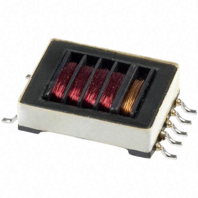
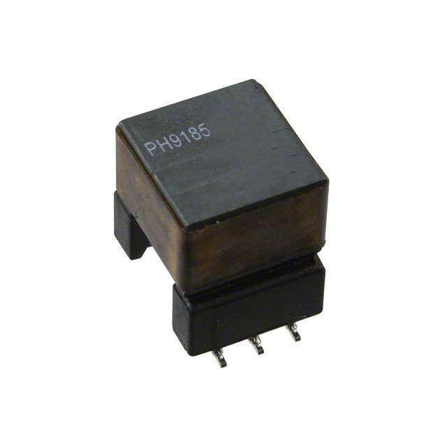
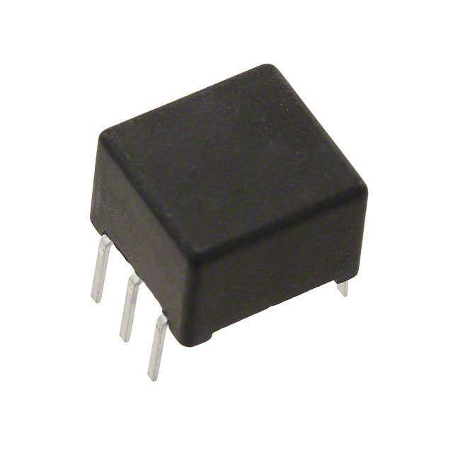
| 描述 | XFRMR 5V IN/OUT MAX 253 DIP电源变压器 MAX253 CNVR XFRMR 5Vin 5Vout 4000VDC |
| 产品分类 | |
| 品牌 | Murata Power Solutions |
| 产品手册 | |
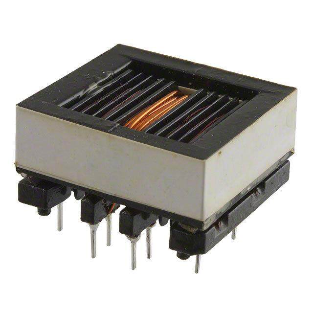
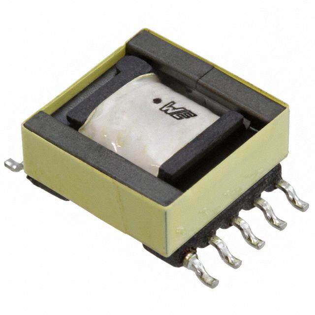
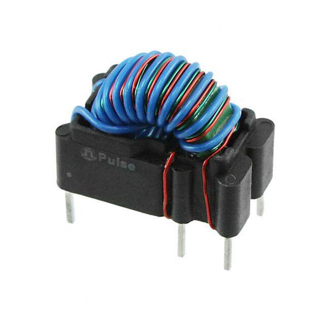
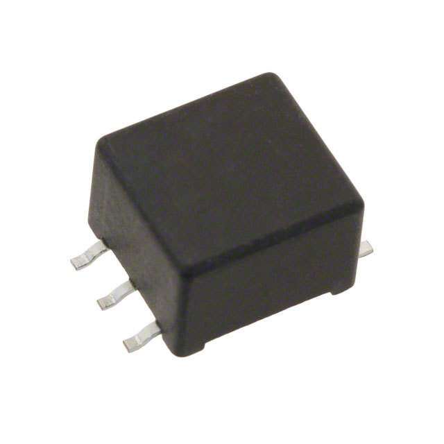
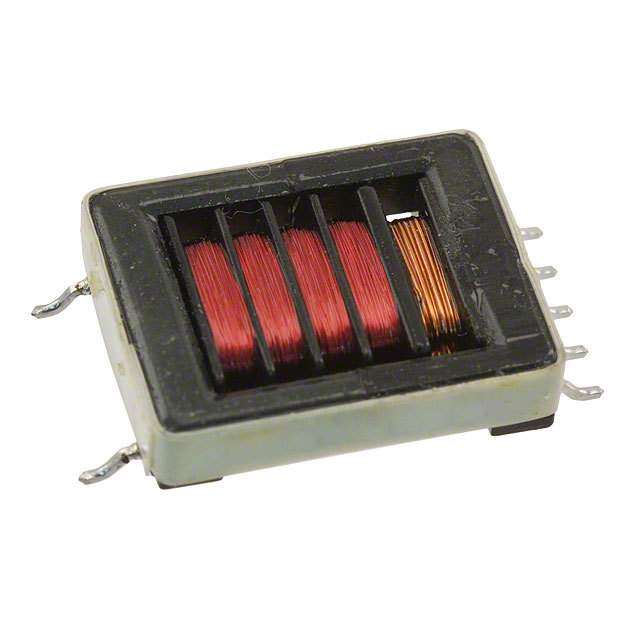
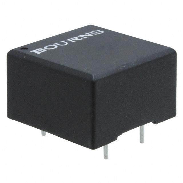
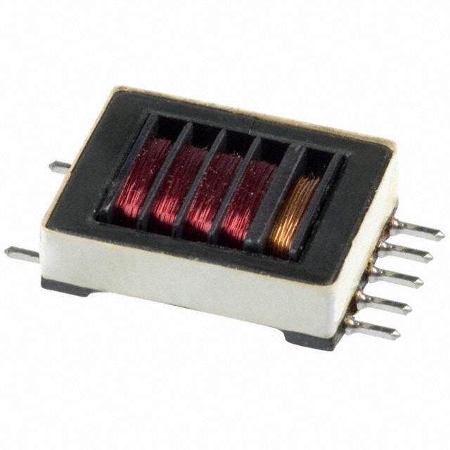
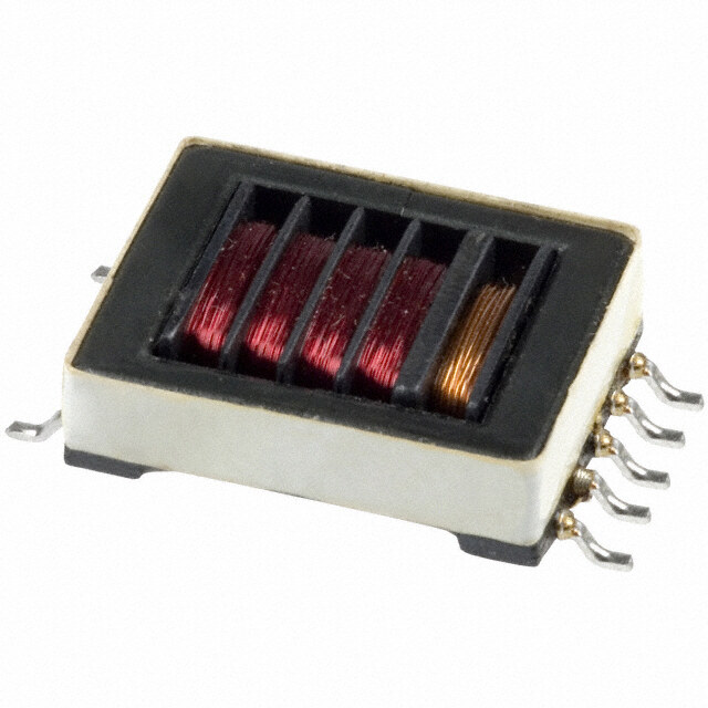
| 产品图片 |
|
| rohs | RoHS 合规性豁免无铅 / 符合限制有害物质指令(RoHS)规范要求 |
| 产品系列 | 电源变压器,Murata Power Solutions 78253/55VC78253 |
| 数据手册 | |
| 产品型号 | 78253/55VC |
| 一次绕组 | Single Primary Winding |
| 二次绕组 | Single Secondary Winding |
| 产品 | Toroidal Power Transformers |
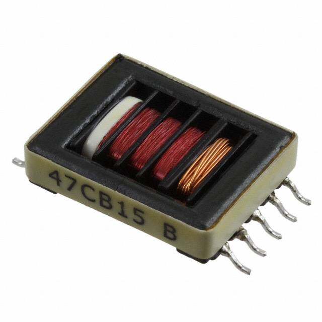
| 产品目录绘图 |
|
| 产品种类 | |
| 其它名称 | 7825355VC |
| 初级电压额定值 | 5 V |
| 功率额定值 | 1 W |
| 匝数比 | 1:1.3 |
| 商标 | Murata Power Solutions |
| 大小/尺寸 | 9.52mm 长 x 9.00mm 宽 |
| 安装类型 | 通孔 |
| 安装风格 | Through Hole |
| 宽度 | 9 mm |
| 封装 | Tube |
| 工作温度范围 | - 40 C to + 85 C |
| 工厂包装数量 | 50 |
| 标准包装 | 50 |
| 次级电压额定值 | 5 V |
| 次级电流额定值 | 200 mA |
| 电感 | 240 uH |
| 端接类型 | Through Hole |
| 类型 | Compatible Converter Transformer |
| 配套使用产品/相关产品 | MAX253 |
| 长度 | 9.52 mm |
| 高度 | 6.35 mm |
| 高度-安装(最大值) | 6.60mm |


- 商务部:美国ITC正式对集成电路等产品启动337调查
- 曝三星4nm工艺存在良率问题 高通将骁龙8 Gen1或转产台积电
- 太阳诱电将投资9.5亿元在常州建新厂生产MLCC 预计2023年完工
- 英特尔发布欧洲新工厂建设计划 深化IDM 2.0 战略
- 台积电先进制程称霸业界 有大客户加持明年业绩稳了
- 达到5530亿美元!SIA预计今年全球半导体销售额将创下新高
- 英特尔拟将自动驾驶子公司Mobileye上市 估值或超500亿美元
- 三星加码芯片和SET,合并消费电子和移动部门,撤换高东真等 CEO
- 三星电子宣布重大人事变动 还合并消费电子和移动部门
- 海关总署:前11个月进口集成电路产品价值2.52万亿元 增长14.8%

PDF Datasheet 数据手册内容提取
78253 Series www.murata-ps.com MAX253 Compatible Converter Transformers SELECTION GUIDE Output Max. Output Isolation Input Voltage Turns Package Order Code Voltage Current Voltage Ratio Style V V mA VDC 78253/35C DIL 3.3 5.0 100 1500 1:2.27 78253/35MC SM 78253/55C DIL 5.0 5.0 200 1500 1:1.31 78253/55MC SM 78253/35VC DIL 3.3 5.0 100 4000 1:2.14 FEATURES 78253/35MVC SM 78253/55VC DIL (cid:132) RoHS compliant 5.0 5.0 200 4000 1:1.33 78253/55MVC SM (cid:132)(cid:3)Maxim MAX253 compatible ORDER CODE DETAILS (cid:132)(cid:3)3.3V and 5V versions Order Code Package Type Packaging Type Quantity (cid:132)(cid:3)Isolation to 4kVDC 78253/XX(V)C 6 Pin DIL Tube 50 78253/XXM(V)C 6 Pin SM Tube 50 (cid:132)(cid:3)Frequency range to 500kHZ 78253/XXM(V)C-R 6 Pin SM Tape & Reel 500 (cid:132)(cid:3)Toroidal construction 78253/35(M)C CHARACTERISTICS (cid:132)(cid:3)Industry-standard pinout Parameter Conditions Min. Typ. Max. Units Primary Inductance, L 100kHz, 250mV 0.30 0.38 0.46 mH (cid:132)(cid:3)UL 94 V-0 package materials P Secondary Inductance, L 100kHz, 250mV 1.60 2.00 2.40 mH S (cid:132)(cid:3)Fully encapsulated Leakage Inductance, L 100kHz, 250mV 0.30 1.00 μH L (cid:132)(cid:3)Low profile Interwinding Capacitance, CWW 100kHz, 250mV 30 50 pF Primary D.C. Resistance, R >0.1VDC 0.40 1.00 Ω (cid:132)(cid:3)Surface mount option DC Volt-time Product, Et Pins 1/2 or 2/3 30 35 Vμs (cid:132)(cid:3)Industrial temperature range 78253/55(M)C CHARACTERISTICS Parameter Conditions Min. Typ. Max. Units DESCRIPTION Primary Inductance, L 100kHz, 250mV 0.60 0.83 1.10 mH P Secondary Inductance, L 100kHz, 250mV 1.10 1.40 1.70 mH The 78253 series of converter transformers are S Leakage Inductance, L 100kHz, 250mV 0.35 1.00 μH specifically designed for use with the MAX253 L Interwinding Capacitance, C 100kHz, 250mV 30 50 pF chip set to provide isolated power supplies. The WW Primary D.C. Resistance, R >0.1VDC 0.70 1.50 Ω 5V version can supply 1W and the 3.3V version DC Volt-time Product, Et Pins 1/2 or 2/3 40 50 Vμs can supply 500mW. A centre tapped secondary winding allows for full bridge, half bridge or 78253/35(M)VC CHARACTERISTICS voltage doubling. Parameter Conditions Min. Typ. Max. Units Primary Inductance, L 100kHz, 20mV 110 142 185 μH P Secondary Inductance, L 100kHz, 20mV 550 710 850 μH Surface-mount parts S Leakage Inductance, L 100kHz, 250mV 3.00 5.00 μH L The surface-mount (M suffix) products are not Interwinding Capacitance, C 100kHz, 250mV 4.20 8.00 pF WW recommended for new designs. For existing designs, Primary D.C. Resistance, R >0.1VDC 0.30 0.50 Ω DC however, Murata Power Solutions will continue to Volt-time Product, Et Pins 1/2 or 2/3 18 22 Vμs manufacture and fully support these parts. 78253/55(M)VC CHARACTERISTICS For recommended alternatives please refer to the Parameter Conditions Min. Typ. Max. Units 78253J Series datasheet. Primary Inductance, L 100kHz, 20mV 190 240 310 μH P Secondary Inductance, L 100kHz, 20mV 350 444 540 μH S Leakage Inductance, L 100kHz, 250mV 5.20 8.00 μH L Interwinding Capacitance, C 100kHz, 250mV 4.20 8.00 pF WW Primary D.C. Resistance, R >0.1VDC 0.40 0.60 Ω DC Volt-time Product, Et Pins 1/2 or 2/3 25 28 Vμs All specifications typical at T=25°C A For full details go to www.murata-ps.com/rohs www.murata-ps.com/support KMP_78253C_D06 Page 1 of 5
78253 Series MAX253 Compatible Converter Transformers ABSOLUTE MAXIMUM RATINGS Operating free air temperature range -40°C to 85°C Storage temperature range -50°C to 125°C Lead Temperature 1.5mm from case for 10 seconds 300°C Peak current I 400mA PK Isolation voltage 78253/XX(M)C (flash tested for 1 second) 1500VDC Isolation voltage 78253/XX(M)VC (flash tested for 1 second) 4000VDC PACKAGE SPECIFICATIONS MECHANICAL DIMENSIONS 6 Pin DIL 6 Pin SM 0.5 (12.70) 0.375 0.375 (9.52) MAX Top View (9.52) MAX Top View Primary Secondary Primary Secondary 1 6 1 6 0.354 0.354 (9.0) MAX 2 5 (9.0) MAX 2 5 78253/35C 78253/55MC XYYWW 3 4 XYYWW 3 4 0.25 0.25 (6.35) (6.35) 0.135±0.02 0.012 0.30 (3.44±0.50) (0.008 0.20) 0.035 0.025 (0.63) (0.90) 0.1 0.021 (0.53) 0.012(0.30) 0.025 (0.63) (2.54) 0.008(0.20) 0.021 (0.53) 0.40 0.1 (2.54) (10.16) Unless otherwise stated all dimensions in inches (mm) ±0.01 (0.25). All pins on a 0.1 (2.54) pitch and within ±0.01 (0.25) of true position. Package weight 1.0g Typ. RECOMMENDED FOOTPRINT DETAILS 6 Pin DIL 6 Pin SM 0.10 (2.54) 0.10 (2.54) 0.06 (1.60) 0.10 (2.54) Ø0.05 (1.20)+0.006 (0.15) -0.000 (0.00) 0.04 (1.00) 0.45 (11.50) Unless otherwise stated all dimensions in inches (mm) ±0.01 (0.25). All pins on a 0.1 (2.54) pitch and within ±0.01 (0.25) of true position. www.murata-ps.com/support KMP_78253C_D06 Page 2 of 5
78253 Series MAX253 Compatible Converter Transformers TYPICAL CHARACTERISTICS (VOLTAGE CURVES) VOLTAGE CURVES 78253/35(M)C 78253/55(M)C 10 10 8 8 V) V) e ( 6 e (6 g g a a olt olt ut V 4 ut V4 p p ut ut O 2 O2 0 0 0 20 40 60 80 100 120 0 100 200 300 400 Output Current (mA) Output Current (mA) 78253/35(M)VC 78253/55(M)VC 10 10 8 8 V) V) e ( 6 e (6 g g a a olt olt ut V 4 ut V4 p p ut ut O 2 O2 0 0 0 20 40 60 80 100 0 100 200 300 400 Output Current (mA) Output Current (mA) EFFICIENCY CURVES 78253/35(M)C 78253/55(M)C 100 100 80 80 %) 60 %)60 cy ( cy ( en 40 en40 ci ci Effi Effi 20 20 0 0 0 20 40 60 80 100 120 0 100 200 300 400 Output Current (mA) Output Current (mA) 78253/35(M)VC 78253/55(M)VC 100 100 80 80 %) 60 %)60 cy ( cy ( en 40 en40 ci ci Effi Effi 20 20 0 0 0 20 40 60 80 100 0 100 200 300 400 Output Current (mA) Output Current (mA) All curves are derived from testing with the Maxim MAX235 IC using the circuit shown in application note MPAN-03 ( download at http://www.murata-ps.com/data/apnotes/mpan-03.pdf). www.murata-ps.com/support KMP_78253C_D06 Page 3 of 5
78253 Series MAX253 Compatible Converter Transformers TYPICAL CHARACTERISTICS (VOLTAGE CURVES) continued VOLTAGE DEVIATION 78253/35(M)C 78253/55(M)C 110 110 al al n n mi 105 mi 105 o o e Deviation from N 25°C Output (%) 10905 e Deviation from N 25°C Output (%)10905 g g a a olt olt V 90 V 90 -50 -25 0 25 50 75 100 -50 -25 0 25 50 75 100 Temperature (°C) Temperature (°C) 78253/35(M)VC 78253/55(M)VC 110 110 al al n n omi 105 omi 105 e Deviation from N 25°C Output (%) 10905 e Deviation from N 25°C Output (%)10905 g g a a olt olt V 90 V 90 -50 -25 0 25 50 75 100 -50 -25 0 25 50 75 100 Temperature (°C) Temperature (°C) TECHNICAL NOTES SOLDERING INFORMATION1 ISOLATION VOLTAGE REPEATED HIGH-VOLTAGE Pin finish Matte tin ‘Hi Pot Test’, ‘Flash Tested’, ‘Withstand Volt- ISOLATION TESTING Peak wave solder temperature 300˚C for 10 seconds age’, ‘Proof Voltage’, ‘Dielectric Withstand It is well known that repeated high-voltage Peak reflow temperature 220˚C2 Voltage’ & ‘Isolation Test Voltage’ are all terms isolation testing of a barrier component can that relate to the same thing, a test voltage, actually degrade isolation capability, to a applied for a specified time, across a compo- lesser or greater degree depending on ma- TUBE OUTLINE DIMENSIONS nent designed to provide electrical isolation, to terials, construction and environment. This verify the integrity of that isolation. series has toroidal isolation transformers, 0.43 (10.95) All products in this series are 100% production with no additional insulation between pri- tested at their stated isolation voltage. mary and secondary windings of enameled 0.16 (4.00) wire. While parts can be expected to with- A question commonly asked is, “What is the stand several times the stated test voltage, continuous voltage that can be applied across the isolation capability does depend on the 0.023±0.005 0.51 the part in normal operation?” wire insulation. Any material, including this (0.60±0.15) (12.95) For a part holding no specific agency approv- enamel (typically polyurethane) is suscep- als both input and output should normally be tible to eventual chemical degradation when 0.22 (5.50) maintained within SELV limits i.e. less than subject to very high applied voltages thus 42.4V peak, or 60VDC. The isolation test implying that the number of tests should be (03..1850) voltage represents a measure of immunity to strictly limited. We therefore strongly advise transient voltages and the part should never against repeated high voltage isolation test- 0.62 (15.70) be used as an element of a safety isolation ing, but if it is absolutely required, that the Tube length: 18.3±0.08 (465±2). Tube quantity: 50. system. The part could be expected to function voltage be reduced by 20% from specified Tube material: Antistatic coated clear pvc. correctly with several hundred volts offset test voltage. Unless otherwise stated all dimensions in inches(mm) ±0.01 (0.25). applied continuously across the isolation bar- rier; but then the circuitry on both sides of the This consideration equally applies to agency All specifications typical at T=25°C barrier must be regarded as operating at an recognised parts rated for better than 1 For further information, plAease visit www.murata-ps.com/rohs unsafe voltage and further isolation/insulation functional isolation where the wire enamel 2 For high temperature reflow parts see 78253J series. systems must form a barrier between these insulation is always supplemented by a circuits and any user-accessible circuitry ac- further insulation system of physical spacing cording to safety standard requirements. or barriers. www.murata-ps.com/support KMP_78253C_D06 Page 4 of 5
78253 Series MAX253 Compatible Converter Transformers TAPE & REEL SPECIFICATIONS REEL OUTLINE DIMENSIONS Ø15.039 (382) Max. 2.36 (60) Min. 0.94-1.08 (23.9-27.4)* Ø0.53 (13.50) 0.50 (12.80) Leader section 15.7 (400) Min. 3.9 (100) Min. 0.059 (1.50) Min. 1.20 (30.4) Max. (cid:103) Goods enclosure section 0.96 (24.4)(cid:103) 1.04 (26.4) Trailer section Reel quantity: 500 6.3 (160) Min. Unless otherwise stated all dimensions in inches (mm) ±0.01(0.25). * Includes flange distortion at outer edge. Ø0.80 (20.20) Min. (cid:103) Measured at hub. TAPE OUTLINE DIMENSIONS 0.069 (1.75) 0.157 (4.00) 0.079 (2.00) 0.059 + - 00 .. 00 00 04 (1.50 + - 00 .. 01 00 ) 21.0+003.0+0.945 (24.00 )0400.-01.0- 0.453 (11.50) WWYYXCM5335287 Cover tape 0.369 (9.37) 0.472 (12.00) 0.024 (0.60) Max. 0.283 (7.20) Direction of unreeling Unless otherwise stated all dimensions in inches (mm) ±0.01(0.25). This product is subject to the following operating requirements and the Life and Safety Critical Application Sales Policy: Refer to: http://www.murata-ps.com/requirements/ Murata Power Solutions, Inc. makes no representation that the use of its products in the circuits described herein, or the use of other technical information contained herein, will not infringe upon existing or future patent rights. The descriptions contained herein do not imply the granting of licenses to make, use, or sell equipment constructed in accordance therewith. Specifications are subject to change without notice. © 2018 Murata Power Solutions, Inc. www.murata-ps.com/support KMP_78253C_D06 Page 5 of 5
Mouser Electronics Authorized Distributor Click to View Pricing, Inventory, Delivery & Lifecycle Information: M urata: 78253/55 78253/35MV 78253/35M 78253/35V 78253/55M 78253/35 78253/55MV 78253/55V 78253/55MVC 78253/35VC 78253/35MC 78253/35MVC 78253/55VC 78253/55MC 78253/35C 78253/55C 78253/35MC-R 78253/35MVC-R 78253/55MC-R 78253/55MVC-R