ICGOO在线商城 > 工具 > 压接器,施用器,压力机 > 58573-1

 Datasheet下载
- 型号: 58573-1
- 制造商: CORCOM/TYCO ELECTRONICS
- 库位|库存: xxxx|xxxx
- 要求:
| 数量阶梯 | 香港交货 | 国内含税 |
| +xxxx | $xxxx | ¥xxxx |
查看当月历史价格
查看今年历史价格
58573-1产品简介:
ICGOO电子元器件商城为您提供58573-1由CORCOM/TYCO ELECTRONICS设计生产,在icgoo商城现货销售,并且可以通过原厂、代理商等渠道进行代购。 58573-1价格参考¥3102.22-¥3239.87。CORCOM/TYCO ELECTRONICS58573-1封装/规格:压接器,施用器,压力机, 手动压接器 工具 接头 侧面插入,棘齿。您可以下载58573-1参考资料、Datasheet数据手册功能说明书,资料中有58573-1 详细功能的应用电路图电压和使用方法及教程。
TE Connectivity AMP Connectors品牌的型号58573-1属于压接器/压力机类工具,主要用于电子连接器的压接工艺。该工具广泛应用于汽车、通信、工业控制等领域,适用于对线缆与连接器之间的端子进行高效、可靠的压接操作。其设计旨在确保压接力的均匀性和稳定性,从而提升连接的电气性能和机械强度。该型号适用于特定尺寸的端子,常用于批量生产环境中,以保证压接质量和操作效率。
| 参数 | 数值 |
| 产品目录 | |
| 描述 | TOOL HAND FOR SPARE WIRE CAPS |
| 产品分类 | |
| 品牌 | TE Connectivity |
| 数据手册 | http://www.te.com/commerce/DocumentDelivery/DDEController?Action=srchrtrv&DocNm=408-4251&DocType=SS&DocLang=EN |
| 产品图片 |
|
| 产品型号 | 58573-1 |
| rohs | 不适用 / 不适用 |
| 产品系列 | Pro-Crimper III,AMP |
| 其它名称 | 585731 |
| 工具类型 | 手动压接器 |
| 标准包装 | 1 |
| 特性 | 侧面插入,棘齿 |
| 特色产品 | http://www.digikey.cn/product-highlights/zh/procrimper-iii-hand-tools/52602 |
| 视频文件 | http://www.digikey.cn/classic/video.aspx?PlayerID=1364138032001&width=640&height=505&videoID=3630218868001 |
| 配套使用产品/相关产品 | 接头 |
| 配用 | /product-detail/zh/324487/324487-ND/2259386/product-detail/zh/324693/324693-ND/2258940/product-detail/zh/324696/324696-ND/1150459/product-detail/zh/324486/A27480-ND/299252/product-detail/zh/324484/A27478-ND/299251/product-detail/zh/324485/A27479-ND/299248/product-detail/zh/324695/A27570-ND/292831/product-detail/zh/324694/A27569-ND/292830 |


- 商务部:美国ITC正式对集成电路等产品启动337调查
- 曝三星4nm工艺存在良率问题 高通将骁龙8 Gen1或转产台积电
- 太阳诱电将投资9.5亿元在常州建新厂生产MLCC 预计2023年完工
- 英特尔发布欧洲新工厂建设计划 深化IDM 2.0 战略
- 台积电先进制程称霸业界 有大客户加持明年业绩稳了
- 达到5530亿美元!SIA预计今年全球半导体销售额将创下新高
- 英特尔拟将自动驾驶子公司Mobileye上市 估值或超500亿美元
- 三星加码芯片和SET,合并消费电子和移动部门,撤换高东真等 CEO
- 三星电子宣布重大人事变动 还合并消费电子和移动部门
- 海关总署:前11个月进口集成电路产品价值2.52万亿元 增长14.8%

PDF Datasheet 数据手册内容提取
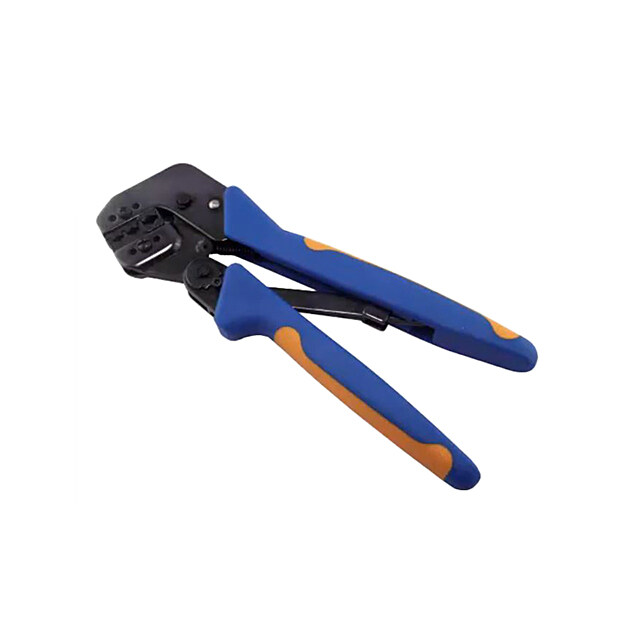
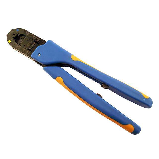
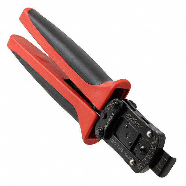
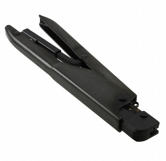
Instruction Sheet PRO-CRIMPER* III Hand Crimping 408-4251 Tool Assembly 58573-1 with Die Assembly 58573-2 21 APR 11 Rev F PROPER USE GUIDELINES Cumulative Trauma Disorders can result from the prolonged use of manually powered hand tools. Hand tools are intended for occasional use and low volume applications. A wide selection of powered application equipment for extended-use, production operations is available. Stationary Jaw Pivot Pin Die Assembly Back of Tool Frame (Wire Side) Moving Jaw Ratchet Die Retaining Screw PRO-CRIMPER III Hand Tool (2 Places) Frame 354940-1 (408-9930) Ratchet Adjustment Wheel Stationary Handle The PRO-CRIMPER III Hand Crimping Tool is a “Commercial" grade tool and is designed primarily for field installation, repair, maintenance work, or prototyping in industrial, commercial, or institutional applications. Product crimped with this tool will meet the crimp height requirement for hand tools in the appropriate Application Specification (114-series), but may not comply with other feature parameters of the Moving Handle specification. TE offers a variety of tools to satisfy your performance requirements. For additional information, contact the Tooling Assistance Center at 1-800-722-1111. DIE ASSEMBLY WIRE INSULATION SPARE WIRE CAP SPARE WIRE CAP DIE ASSEMBLY CRIMPING CHAMBER DIAMETER RANGE MARKING (mm [in.]) Standard Moisture Resistant COLOR CODE W 1.22-1.91 [.048-.075] 324484 324693 White R 2.03-2.92 [.080-.115] 324485 324694 Red 58573-2 B 3.05-3.68 [.120-.145] 324486 324695 Blue Y 3.81-5.33 [.150-.210] 324487 324696 Yellow Figure 1 1. INTRODUCTION For additional information on the hand tool frame, refer to 408-9930. PRO-CRIMPER III Hand Tool Assembly 58573-1 consists of PRO-CRIMPER III Hand Tool Frame Reasons for reissue of this instruction sheet are 354940-1 and Die Assembly 58573-2. The tool provided in Section 8, REVISION SUMMARY. assembly is used to crimp the spare wire caps listed in Figure 1 onto single unstripped wire with thin copper 2. DESCRIPTION (See Figure 1) insert and with or without a moisture-resistant inhibitor. The tool consist of a stationary jaw and handle, a Read these instructions thoroughly before using the moving jaw and handle, and an adjustable ratchet that tool assembly. ensures full crimping. The tool features a ratchet adjustment wheel for adjusting the crimp height. Dimensions in this instruction sheet are in metric NOTE units [with U.S. customary units in brackets]. The die assembly consists of an indenter (stationary i Figures are not drawn to scale. die) and an anvil (moving die). When closed, the dies form four crimping chambers. Each die is held in the tool frame by a single screw. ©2011 Tyco Electronics Corporation, a TE Connectivity Ltd. Company TOOLING ASSISTANCE CENTER 1-800-722-1111 This controlled document is subject to change. 1 of 4 All Rights Reserved PRODUCT INFORMATION 1-800-522-6752 For latest revision and Regional Customer Service, *Trademark visit our website at www.te.com TE Connectivity, TE connectivity (logo), and TE (logo) are trademarks. Other logos, product and/or Company names may be trademarks of their respective owners. LOC B
408-4251 3. INSTALLATION AND REMOVAL OF DIE ASSEMBLY 5. Close the tool handles until the ratchet releases. 1. Close the tool handles until the ratchet releases, 6. Allow the tool handles to open FULLY, and turn then allow the handles to open fully. the spare wire cap and wire one quarter of a turn while pulling lightly on the wire until the spare wire 2. Insert the dies into the tool jaws as shown in cap is free from the crimping chamber. Figure 2, and align the retaining holes in each die with the associated hole in the tool. 7. Refer to Figure 3, and inspect the crimped spare wire cap for the following: 3. Thread, but do not tighten, the die retaining screws into the holes. — The crimp should be near the center of the insert in the spare wire cap, and the wire should be 4. Carefully close the tool handles, making sure that bottomed in the spare wire cap. the dies align properly. — Double check that the correct spare wire cap was 5. Tighten the die retaining screws using the used for the wire insulation diameter, and make appropriate screwdriver. sure that the correct crimping chamber was used. 6. To disassemble, close the tool handles until the If the spare wire cap fails inspection, cut the wire ratchet releases, remove the two die retaining from the spare wire cap, then apply a new spare screws, and slide the dies out of the tool jaws. wire cap to the wire by carefully following the crimping procedure. DO NOT use defective or damaged products. Jaws CAUTION ! Indenter Die Die 2 Retaining Screws 1 4 3 1 Crimp near center of insert; spare wire cap was fully bottomed in closed dies. Anvil 2 Correct wire insulation diameter for spare wire cap was used. Die 3 Wire bottomed in spare wire cap. 4 Spare wire cap insulation color matches die crimping Figure 2 chamber marking. 4. CRIMPING PROCEDURE Figure 3 Refer to Figure 1, and select a spare wire cap for the insulation diameter of the wire being used. Then 5. RATCHET ADJUSTMENT proceed as follows: The tool ratchet mechanism features an adjustment 1. Close the tool handles until the ratchet releases, wheel with numbered settings. The adjustment wheel then allow the handles to open FULLY. controls the amount of handle pressure exerted on the jaws during crimping. If the crimp is not acceptable, 2. Identify the color code of the spare wire cap, and adjust the ratchet as follows: insert the spare wire cap into the crimping chamber with the same color code. Make sure that the spare 1. Remove the lockscrew from the ratchet wire cap is fully inserted. adjustment wheel. Refer to Figure 4. 3. Begin closing the tool handles until the spare wire 2. Using a screwdriver, adjust the ratchet wheel cap is held firmly in place. DO NOT deform the cap. from the front of the tool. 4. Insert the unstripped wire completely into the 3. Observe the ratchet adjustment wheel. If a tighter spare wire cap. When bottoming the wire in a crimp is required, rotate the adjustment wheel moisture-resistant spare wire cap, greater insertion counterclockwise to a higher-numbered setting. If a force must be exerted on the wire to displace the looser crimp is required, rotate the adjustment inhibitor in the spare wire cap. wheel clockwise to a lower-numbered setting. Rev F 2 of 4
408-4251 Figure 5 provides dimensions for the die openings. Y R Screwdriver B W Ratchet Adjustment Wheel Lockscrew Note: Not to Scale Figure 4 DIE DIE OPENING DIMENSION (mm [in.]) 4. Re-install the lockscrew. ASSEMBLY W R B Y 5. Make a sample crimp. If the crimp is acceptable, 1.83 2.26 2.95 3.61 the adjustment setting is correct. If the crimp is 58573-2 [.072] [.089] [.116] [.142] unacceptable, continue to adjust the ratchet, and again measure a sample crimp. Figure 5 6. MAINTENANCE AND INSPECTION 7. REPLACEMENT AND REPAIR 6.1. Maintenance Available separately, Repair Kit 679221-1 includes a replacement nut and a variety of pins, rings, screws, 1. Ensure that the tool frame and dies are clean by and springs. If the dies are damaged or worn wiping them with a clean, soft cloth. Remove any excessively, they must be replaced. debris with a clean, soft brush. Do not use objects that could damage any components. Order the repair kit, tool assembly, and die assembly through your representative, or call 1-800-526-5142, 2. When not in use, keep tool handles closed to or send a facsimile of your purchase order to prevent objects from becoming lodged in the dies, 717-986-7605, or write to: and store in a clean, dry area. CUSTOMER SERVICE (038-035) 3. Remove all lubrication and accumulated film from TYCO ELECTRONICS CORPORATION the dies by immersing the dies in a suitable PO BOX 3608 commercial degreaser. HARRISBURG PA 17105-3608 6.2. Visual Inspection 8. REVISION SUMMARY 1. Inspection of the tool and dies should be made on Revisions to this instruction sheet include: a regular basis to ensure that they have not become worn or damaged. •Changed company logo 2. Make sure that the proper die retaining screws are properly secured. 3. Inspect the crimping chambers of the die assembly for flattened, chipped, worn, or broken areas. If damage or abnormal wear is evident, the dies must be replaced. Refer to Section 7, REPLACEMENT AND REPAIR. 6.3. Measuring Die Opening The tool assembly will perform correctly as long as: (1) the product specified is correct for the die assembly, (2) the correct product is used in the matching crimping chamber of the die assembly, (3) the die assembly has been measured to ensure that the openings are correct, and (4) the dies bottom on each other. Rev F 3 of 4
408-4251 Tooling Compatible with Die Assembly 58573-2 PRO-CRIMPER III Hand Tool Frame 354940-1 SDE-SA Hand Tool 9-1478240-0 (Instruction Sheet 408-9930) (Instruction Sheet 408-8851) SDE Bench Terminator 1490076-2 626 Adapter 679304-1 (Customer Manual 409-10052) (Instruction Sheet 408-4070) Closed Head Assembly 2031460-1 “C”-Head Assembly 2031450-1 (Instruction Sheet 408-10312) (Instruction Sheet 408-10311) Electro-Hydraulic (BT 3500 Battery-Hydraulic) Hand Tool Kits 2031400-[ ] (Customer Manual 409-10095) Rev F 4 of 4
Mouser Electronics Authorized Distributor Click to View Pricing, Inventory, Delivery & Lifecycle Information: T E Connectivity: 58573-1