
 Datasheet下载
- 型号: 47820
- 制造商: CORCOM/TYCO ELECTRONICS
- 库位|库存: xxxx|xxxx
- 要求:
| 数量阶梯 | 香港交货 | 国内含税 |
| +xxxx | $xxxx | ¥xxxx |
查看当月历史价格
查看今年历史价格
47820产品简介:
ICGOO电子元器件商城为您提供47820由CORCOM/TYCO ELECTRONICS设计生产,在icgoo商城现货销售,并且可以通过原厂、代理商等渠道进行代购。 47820价格参考。CORCOM/TYCO ELECTRONICS47820封装/规格:模具組, 。您可以下载47820参考资料、Datasheet数据手册功能说明书,资料中有47820 详细功能的应用电路图电压和使用方法及教程。
TE Connectivity AMP Connectors品牌的47820型号属于模具组(Molded Connector Assemblies)分类,是一种常用于工业和自动化领域的连接器产品。该型号通常为DIN 41612类型的连接器,具备优良的电气性能和机械稳定性。

47820型号主要应用于工业控制系统、PLC(可编程逻辑控制器)、I/O模块、测量设备及自动化设备中,适用于需要高可靠性和稳定信号传输的场合。其结构坚固,具备良好的抗振动和抗干扰能力,适合在较为恶劣的工业环境中使用。

该连接器也常见于轨道交通、能源、楼宇自动化等行业的电气控制系统中,用于实现设备之间的安全、可靠的电气连接。其模具成型的结构设计,不仅提升了产品的防护等级,也增强了其在复杂环境中的耐用性。

总之,TE Connectivity AMP Connectors 47820型号因其高可靠性、优良的电气性能和广泛的适用性,广泛应用于各类工业自动化和控制系统中,是实现设备间稳定连接的重要组件。
| 参数 | 数值 |
| 产品目录 | |
| CompatibleTools | 59974-1, 69051 |
| 描述 | DIE TERMINYL 69051 8AWG |
| 产品分类 | |
| 品牌 | TE Connectivity |
| 数据手册 | http://www.te.com/commerce/DocumentDelivery/DDEController?Action=srchrtrv&DocNm=408-1729&DocType=SS&DocLang=EN |
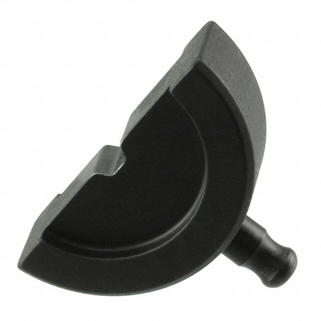
| 产品图片 |
|
| 产品型号 | 47820 |
| rohs | 不适用 / 不适用 |
| 产品系列 | Plasti-Grip; Terminyl,AMP |
| 工具类型 | 成套模具,液压 |
| 标准包装 | 1 |
| 电缆组 | - |
| 规格 | - |
| 配套使用产品/相关产品 | 接片和端子,8 AWG |
| 配用 | /product-detail/zh/328569/328569-ND/2262450/product-detail/zh/324657/324657-ND/2259277/product-detail/zh/696049-1/696049-1-ND/1153903/product-detail/zh/52263-5/52263-5-ND/1153594/product-detail/zh/324658/324658-ND/1150458/product-detail/zh/696050-1/696050-1-ND/1137028/product-detail/zh/53944-1/53944-1-ND/1136898/product-detail/zh/324625/324625-ND/1131629/product-detail/zh/54725-1/54725-1-ND/659772/product-detail/zh/55621-1/A28196-ND/333592/product-detail/zh/324044/A27381-ND/299267/product-detail/zh/324043/A27379-ND/299266/product-detail/zh/324082/A27380-ND/299249/product-detail/zh/52263-1/A27317-ND/298028/product-detail/zh/52263/A27318-ND/298024/product-detail/zh/52041-3/A27319-ND/298023/product-detail/zh/53041/A27378-ND/298006/product-detail/zh/55654-1/A27563-ND/294107/product-detail/zh/52291/A27321-ND/293698/product-detail/zh/52291-1/A27531-ND/293697/product-detail/zh/52262-1/A27532-ND/293686/product-detail/zh/52041/A27530-ND/293670/product-detail/zh/52041-1/A27320-ND/293667/product-detail/zh/324045/A27382-ND/292799 |


- 商务部:美国ITC正式对集成电路等产品启动337调查
- 曝三星4nm工艺存在良率问题 高通将骁龙8 Gen1或转产台积电
- 太阳诱电将投资9.5亿元在常州建新厂生产MLCC 预计2023年完工
- 英特尔发布欧洲新工厂建设计划 深化IDM 2.0 战略
- 台积电先进制程称霸业界 有大客户加持明年业绩稳了
- 达到5530亿美元!SIA预计今年全球半导体销售额将创下新高
- 英特尔拟将自动驾驶子公司Mobileye上市 估值或超500亿美元
- 三星加码芯片和SET,合并消费电子和移动部门,撤换高东真等 CEO
- 三星电子宣布重大人事变动 还合并消费电子和移动部门
- 海关总署:前11个月进口集成电路产品价值2.52万亿元 增长14.8%

PDF Datasheet 数据手册内容提取
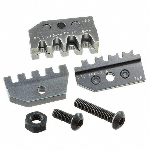
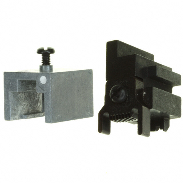
Instruction Sheet 408-1729 Crimping Dies; PN 47820 thru 47825, 47915, and 47918 22 NOV 16 Rev K Crimping Dies; PN 47820 thru 47825, 47915, and 47918 (Typical) Crimping Die Wire Size Head or Tool Part Number Color Code Dot (AWG) 47820 Red 8 Hydraulic Crimping Head 69051 47821 Blue 6 or 47822 Yellow 4 Hydraulic Hand Tool 59974-1 47823 Red 2 47824 Blue 1/0 47825 Yellow 2/0 Hydraulic Crimping Head 69066 47915 Red 3/0 47918 Blue 4/0 Figure 1 1. INTRODUCTION Crimping Dies 47820 through 47823 are used with Crimping Head 69051 or Hand Tool 59974--1. Crimping Dies 47824, 47825, 47915, and 47918 are used with Crimping Head 69066. The dies crimp pre-insulated AMPOWER* terminals onto wire sizes 4 through 1/0 AWG, TERMINYL* terminals and splices onto wire sizes 8 through 4/0 AWG, TERMINYL splices with step-down adapters onto wire sizes 16-14 through 1/0 AWG, and PLASTI-GRIP* terminals and splices onto wire sizes 8 through 4/0 AWG. Refer to Figure 1 to ensure compatibility of crimping die, head or tool, and wire size. NOTE Dimensions in this document are in millimeters [with inches in brackets]. Figures and illustrations are for reference only and are not drawn to scale. For detailed information about the head or tool, refer to the instructions packaged with the head or tool. Reasons for reissue of this instruction sheet are provided in Section 8, REVISION SUMMARY. 2. DESCRIPTION (FIGURE 1) Each crimping die consists of a stationary die (nest) and a moving die (anvil). The stationary die features a locator. Each die contains a color code dot that matches the color code of the terminal and splice. When mated, the dies form a crimping chamber. © 2016 TE Connectivity Ltd. family of companies. PRODUCT INFORMATION 1-800-522-6752 This controlled document is subject to change. 1 of 11 All Rights Reserved. For latest revision and Regional Customer Service, *Trademark visit our website at www.te.com. TE Connectivity, TE connectivity (logo), and TE (logo) are trademarks. Other logos, product, and/or company names may be trademarks of their respective owners.
408-1729 3. DIE INSTALLATION AND REMOVAL DANGER To avoid personal injury, ALWAYS release hydraulic pressure to hose or control and disconnect power unit from power supply before installing or removing dies. 3.1. Installation 1. Remove latch pin and open yoke on crimping head (see Figure 2). Figure 2 2. Loosen the setscrew in the yoke. 3. Insert the shank of the stationary die into the yoke, and tighten the setscrew. NOTE The stationary die has a large shank and the moving die has a small shank, as shown in Figure 2. 4. Extend the ram until the ram setscrew is visible. 5. Loosen the setscrew in the ram. 6. Insert the shank of the moving die into the ram, and tighten the setscrew. CAUTION To avoid damage to the dies, be sure the moving and stationary dies are properly oriented. 7. Activate the tool or power unit to allow the ram to return to the “down” position. 8. Close the yoke and insert the latch pin. 3.2. Removal 1. Remove latch pin and open yoke on crimping head. 2. Loosen the setscrew in the yoke, and remove the stationary die. 3. Extend the ram until the ram setscrew is visible. 4. Loosen setscrew in ram and remove moving die. Rev K 2 of 11
408-1729 4. CRIMPING PROCEDURE 4.1. Crimping Terminals DANGER Avoid personal injury. When operating tool or power unit, exercise caution while holding terminals or wire near crimping area. 1. Strip wire to the dimensions listed in Figure 3. Do not nick or cut the wire strands. Figure 3 2. Select the proper color-coded terminal for the wire size. The wire size stamped on the terminal tongue and on the crimping die must match the wire size selected. 3. Insert stripped wire fully into terminal wire barrel. The end of the conductor must not protrude more than 1.60 mm [.063 in.] beyond the edge of the wire barrel. CAUTION Do NOT turn or twist the wire or terminal during insertion. 4. Remove crimping head latch pin and open yoke. 5. Place the terminal in the stationary die with the edge of the wire barrel resting against the locator and the bottom of the terminal tongue facing the stationary die. See Figure 4. Bottom of Terminal Tongue Facing Stationary Die Edge of Wire Barrel Resting Against Locator Figure 4 Rev K 3 of 11
408-1729 6. Holding the terminal in place, close the yoke and insert the latch pin. CAUTION Be sure latch pin is fully inserted, otherwise damage to the die and tool or head will occur when the tool or power unit is activated. 7. Holding wire in place, activate tool or power unit to complete crimp. 8. When crimp is completed, remove the latch pin, open the yoke, and remove the terminal. NOTE If terminal sticks in die after crimping, apply a rocking action to the terminal to remove it from the die. Wipe light oil on the dies to prevent sticking, or use spray dry lubricant. 9. Inspect the crimp according to Section 5. 4.2. Crimping Splices without Step-Down Adapter DANGER Avoid personal injury. When operating tool or power unit, exercise caution while holding splice or wire near the crimping area. 1. Strip wires to the dimensions listed in Figure 3. Do not nick or cut the wire strands. 2. Select the proper color-coded splice for the wire size. The wire size stamped on the splice and on the crimping die must match the wire size selected. 3. Insert the stripped wire into the wire barrel of the end of the splice to be crimped until the wire bottoms against the wire stop within the splice. 4. Remove crimping head latch pin and open yoke. 5. Place the splice in the stationary die. Grasp the end of the splice to be crimped and point the opposite end toward the top of the head yoke at a 30° (approximate) angle. Rotate the end of the splice to be crimped into the die. Position the edge of the window indent against the locator. Refer to Figure 5. Edge of Window Indent Resting Against Locator Top of Yoke Rotate End of Splice to be Crimped into Stationary Die End of Splice Pointed Toward Top of Yoke at Approximately 30°Angle Figure 5 Rev K 4 of 11
408-1729 6. Holding the splice in place, close the yoke and insert the latch pin. CAUTION Be sure latch pin is fully inserted, otherwise damage to the dies and tool or head will occur when the tool is activated. 7. Holding wire in place, activate tool or power unit to complete first wire barrel crimp. 8. When crimp is completed, remove latch pin, open yoke and remove the splice. NOTE If splice sticks in die after crimping, apply a rocking action to the splice to remove it from the die. Wipe light oil on dies to reduce sticking, or use spray dry lubricant. 9. To crimp the other half of splice, reposition un-crimped end of splice in the stationary die and follow the same procedure used to crimp the first half of splice. 10. Inspect the crimp according to Section 5. 4.3. Crimping Splices with Step-Down Adapter DANGER Avoid personal injury. When operating tool or power unit, exercise caution while holding splice or wire near the crimping area. 1. Strip wires to the dimensions listed in Figure 3. Do not nick or cut the wire strands. 2. Select the proper splice, adapter, and crimping die for the wire size (see Figure 6). NOTE Note that the end of the splice containing the adapter has a different color code. Use the crimping die for the larger wire size to crimp both ends of the splice. For example, use Crimping Die 47820 (for wire size 8 AWG) to crimp both ends of the splice with step-down adapter for stepping down from wire size 8 to 16-14 AWG. Figure 6 3. Insert stripped wire into the wire barrel of the end of the splice to be crimped until the wire bottoms against the wire stop within the splice (refer to Figure 3). 4. Remove crimping head latch pin and open yoke. 5. Place the splice in the stationary die. Grasp the end of the splice to be crimped and point the opposite end toward the top of the head yoke at a 30° (approximate) angle. Rotate the end of the splice to be crimped into the die. Position the edge of the window indent against the locator. Refer to Figure 5. Rev K 5 of 11
408-1729 6. Holding the splice in place, close the yoke and insert the latch pin. CAUTION Be sure latch pin is fully inserted, or damage to the dies and tool or head will occur when the tool is activated. 7. Holding the wire in place, activate tool or power unit to complete first wire barrel crimp. 8. When crimp is completed, remove latch pin, open yoke and remove splice. NOTE If splice sticks in die after crimping, apply a rocking action to the splice to remove it from the die. Wipe light oil on dies to reduce sticking, or use spray dry lubricant. 9. To crimp the other half of splice, reposition un-crimped end of splice in the stationary die and follow the same procedure used to crimp the first half of splice. 10. Inspect the crimp according to Section 5. 4.4. Crimping PLASTI-GRIP Butt Splices DANGER Avoid personal injury. When operating tool or power unit, exercise caution while holding butt splices or wire near crimping area. 1. Strip wires to the dimensions listed in Figure 3. Do not nick or cut the wire strands. 2. Select the proper color-coded butt splice for the wire size. The wire size stamped on the butt splice and on the crimping die must match the wire size selected. 3. Remove crimping head latch pin and open yoke. Remove the stationary die from the yoke, then remove the locator from the stationary die. Re-assemble the stationary die onto the yoke. CAUTION To avoid damage to the dies, be sure the stationary die is properly oriented with the moving die. 4. Insert the stripped wire into the wire barrel of the end of the butt splice to be crimped until the wire bottoms against the wire stop within the splice. 5. Place the butt splice in the stationary die with the wire barrel of the end of the splice to be crimped centered over the crimping chamber (see Figure 7). Figure 7 6. Holding butt splice in place, close the yoke and insert latch pin. CAUTION Be sure latch pin is fully inserted, otherwise damage to the die and tool or head will occur when the tool or power unit is activated. 7. Holding wire in place, activate tool or power unit to complete first wire barrel crimp. Rev K 6 of 11
408-1729 8. When crimp is completed, remove latch pin, open yoke, and remove the butt splice. NOTE If butt splice sticks in die after crimping, apply a rocking action to the butt splice to remove it from the die. Wipe light oil on dies to reduce sticking, or use spray dry lubricant. 9. To crimp the other half of butt splice, reposition un-crimped end of splice in the stationary die and follow the same procedure used to crimp the first half of splice. NOTE Be sure to re-assemble locator onto stationary die after crimping PLASTI-GRIP butt splices. 10. Inspect the crimp according to Section 5. 5. CRIMP INSPECTION Inspect crimped terminals and splices by checking the features described in Figure 9. Use only the terminals and splices that meet the conditions shown in the “ACCEPT” column. 6. MAINTENANCE / INSPECTION DANGER To avoid personal injury, ALWAYS release hydraulic pressure to hose or control and disconnect power unit from power supply before performing maintenance or inspection procedure. Each crimping die is thoroughly inspected before packaging. Since there is a possibility of damage during shipment, the crimping die should be inspected immediately upon arrival at your facility. Regular inspections should be performed by quality control personnel. A record of scheduled inspections should remain with the dies and/or be supplied to supervisory personnel responsible for the dies. Though recommendations call for at least one inspection a month, the inspection frequency should be based on the amount of use, ambient working conditions, operator training and skill, and established company standards. CAUTION Regular inspections should include checking torque setting of (4) screws in accordance with Figure 8. Torque (4) Screws in Accordance with Figure 8. Screw Torque Setting Screw Torque Setting Crimping Die Wire Size Crimping Die Wire Size Specification Specification PN (AWG) PN (AWG) (inch-pounds) (inch-pounds) 47820 8 28 47824 1/0 49 47821 6 28 47825 2/0 49 47822 4 28 47915 3/0 49 47823 2 28 47918 4/0 49 Figure 8 Rev K 7 of 11
408-1729 Figure 9 Rev K 8 of 11
408-1729 6.1. Daily Maintenance It is recommended that each operator of the dies be made aware of-and responsible for-the following steps of daily maintenance: 1. Remove dust, dirt, and other contaminants with a clean brush, or a soft, lint--free cloth. Do NOT use objects that could damage the dies. 2. Make certain the dies are protected with a THIN coat of any good SAE 20 motor oil. Do not oil excessively. 3. When the dies are not in use, mate them and store in a clean, dry area. 6.2. Visual Inspection 1. Remove all lubrication and accumulated film by immersing the dies in a suitable commercial degreaser that will not affect paint or plastic material. 2. Make sure all die components are in place. If replacements are necessary, refer to the replacement parts listed in Figure 12. 3. Check components for wear. Remove and replace worn components. 4. Inspect the crimp area for flattened, chipped, cracked, worn, or broken areas. If damage is evident, the dies must be repaired before returning them to service (see Section 7, REPLACEMENT AND REPAIR). 6.3. Gaging the Crimping Chamber The die closure inspection is accomplished using plug gages. A suggested gage design and the GO and NO- GO diameters of the plug gage elements are shown in Figure 10. Figure 10 Rev K 9 of 11
408-1729 The following procedure is recommended for inspecting the die closures: 1. Mate the dies until it is evident that they have bottomed. Hold the dies in this position. 2. Align the GO element with the crimping chamber. Push element straight into the crimping chamber without using force. The GO element must pass completely through the crimping chamber as shown in Figure 11. 3. Align the NO-GO element and try to insert it straight into the crimping chamber. The NO-GO element may start entry but must not pass completely through as shown in Figure 11. If the crimping chamber conforms to the gage inspection, the crimping die is considered dimensionally correct and should be lubricated with a THIN coat of SAE 20 motor oil. If the crimping chamber DOES NOT conform to the gage inspection not, the dies must be repaired before returning them to service (see Section 7, REPLACEMENT AND REPAIR). For additional information concerning the use of a plug gage, refer to Instruction Sheet 408-7424. Figure 11 7. REPLACEMENT AND REPAIR The parts listed in Figure 12 are customer-replaceable. A complete inventory can be stocked and controlled to prevent lost time when replacement of parts is necessary. Order replacement parts through your TE Connectivity Representative, or call 1-800-526-5142, or send a facsimile of your purchase order to 1-717-986- 7605, or write to: CUSTOMER SERVICE (038-035) TE CONNECTIVITY CORPORATION P.O. BOX 3608 HARRISBURG, PA 17105—3608 NOTE Dies may be returned for evaluation and repair. For die repair service, contact a TE Representative at 1-800-526-5136. Rev K 10 of 11
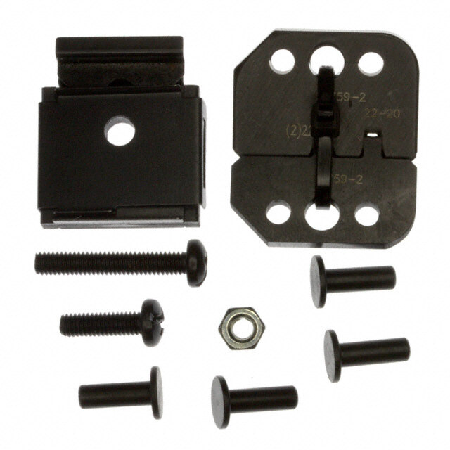
408-1729 8. REVISION SUMMARY Add screw torque and LOCTITE application to process resulting in a new Figure 8, renumbering of subsequent Figures, and CAUTIONS in SECTIONS 6 and 8. Revised quantities of Items 2, 3, 5, 6 in Figure 12. VIEW A VIEW B Replacement Parts Part Numbers for Crimping Die View A View B Qty Item Description Per 47820 47821 47822 47823 47824 47825 47915 47918 Assy 1 47941 47944 47947 47950 47910 47913 47916 47919 Die, Moving 1 Die, 2 47940 47943 47946 47949 47911 47914 47917 47920 1 Stationary 3 313336-1 313336-2 313336-3 313337-1 46606 313337-2 313337-3 313337-4 Locator 1 4 2-21000-0 2-306105-5 2-306105-5 4-306105-4 3-21000-0 Screw 2 5 21018-5 21018-6 Nut 2 6 4-306105-5 2-306105-5 2-21000-2 4-306105-6 6-305927--4 Screw 2 7 313322-4 313322-3 313322-2 313322-1 313323-1 313323-2 313323-3 313323-4 Plate, Flare 2 Plate, Flare, 8 304383 304384 304385 1-45992-0 45992-3 45992-7 45992-8 45992-9 1 Lower Plate, Flare, 9 N/A 45992-2 45992-1 45992-4 45992-5 45992-6 1 Upper CAUTION Apply LOCTITE THREADLOCKER BLUE 242 or LOCTITE THREADLOCKER BLUE 243 to threads of items 4, 5, and 6. Torque screws to applicable specification in Figure 8. Figure 12 LOCTITE, THREADLOCKER BLUE 242, and THREADLOCKER BLUE 243 are trademarks. Rev K 11 of 11
Mouser Electronics Authorized Distributor Click to View Pricing, Inventory, Delivery & Lifecycle Information: T E Connectivity: 47820 47821