ICGOO在线商城 > 电位计,可变电阻器 > 旋转式电位计,变阻器 > 392C2500

 Datasheet下载
- 型号: 392C2500
- 制造商: Honeywell Solid State Electronics
- 库位|库存: xxxx|xxxx
- 要求:
| 数量阶梯 | 香港交货 | 国内含税 |
| +xxxx | $xxxx | ¥xxxx |
查看当月历史价格
查看今年历史价格
392C2500产品简介:
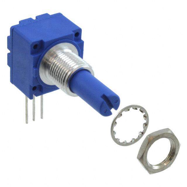
ICGOO电子元器件商城为您提供392C2500由Honeywell Solid State Electronics设计生产,在icgoo商城现货销售,并且可以通过原厂、代理商等渠道进行代购。 392C2500价格参考。Honeywell Solid State Electronics392C2500封装/规格:旋转式电位计,变阻器, 500 Ohm 1 Gang Linear Panel Mount Potentiometer None 1 Turn Conductive Plastic 0.5W, 1/2W PC Pins。您可以下载392C2500参考资料、Datasheet数据手册功能说明书,资料中有392C2500 详细功能的应用电路图电压和使用方法及教程。
Honeywell Sensing and Productivity Solutions 的 392C2500 型号旋转式电位计/变阻器是一种高性能的精密元件,广泛应用于需要精确调节电阻或电压的场景。以下是其主要应用场景:

 1. 工业自动化与控制
   - 用于工业设备中的速度控制、位置反馈和信号调节。
   - 在电机控制系统中,作为可调电阻来调节电机转速或输出功率。
   - 应用于自动化生产线中的传感器校准和参数调整。

 2. 仪器仪表
   - 在测量设备中用作可调电阻,以实现增益调节、零点校准或量程设置。
   - 适用于示波器、万用表等电子测试仪器中的电压或电流调节功能。

 3. 航空航天与国防
   - 用于飞行器或无人机的姿态控制、导航系统和传感器信号调节。
   - 在军事设备中,作为高可靠性元件用于精确控制和数据采集。

 4. 医疗设备
   - 在医疗成像设备(如超声波、X射线机)中调节信号强度或增益。
   - 用于生命体征监测设备中的参数校准和灵敏度调节。

 5. 汽车电子
   - 在车载系统中用于调节灯光亮度、音量控制或其他电子模块的参数。
   - 适用于电动车窗、座椅调节等系统的速度或位置控制。

 6. 消费电子产品
   - 用于音频设备(如收音机、功放)中的音量调节或均衡器设置。
   - 在家用电器中作为可调电阻,控制风扇速度、温度设定等功能。

 7. 科研与实验室设备
   - 在实验装置中用于精确调节电路参数或信号输出。
   - 用于电源供应器、信号发生器等设备中的电压或电流调节。

 特性优势
- 高可靠性:适合严苛环境下的长期使用。
- 精密调节:提供稳定的电阻变化曲线,确保应用精度。
- 耐用性强:能够承受频繁操作和恶劣条件。

综上所述,392C2500 型号的旋转式电位计/变阻器凭借其优异性能,适用于多种行业和领域,特别是在需要精确控制和可靠性的场景中表现出色。
| 参数 | 数值 |
| 产品目录 | |
| 描述 | POT 500 OHM 1/2W COND PLASTIC |
| 产品分类 | 旋转式电位计 - 线性 |
| 品牌 | Honeywell Sensing and Control |
| 数据手册 | http://sensing.honeywell.com/index.php/ci_id/43803/la_id/1/document/1/re_id/0http://sensing.honeywell.com/index.php?ci_id=47380http://sensing.honeywell.com/index.php?ci_id=26158&la_id=1 |
| 产品图片 |
|
| 产品型号 | 392C2500 |
| rohs | 无铅 / 符合限制有害物质指令(RoHS)规范要求 |
| 产品系列 | 392 |
| 其它名称 | RV6L501 |
| 功率(W) | 0.5W,1/2W |
| 包装 | 散装 |
| 圈数 | 单路 |
| 安装类型 | - |
| 容差 | ±10% |
| 尺寸-本体 | 圆形 - 0.510" 直径 x 0.469" 长(12.95mm x 11.91mm) |
| 旋转 | 295° |
| 标准包装 | 100 |
| 温度系数 | - |
| 电阻(Ω) | 500 |
| 电阻材料 | 导电塑料 |
| 端子类型 | 焊片 |
| 致动器直径 | 0.125"(3.18mm) |
| 致动器类型 | 开槽轴 |
| 致动器长度 | 0.625"(15.88mm) |
| 调节类型 | 顶部调节 |


- 商务部:美国ITC正式对集成电路等产品启动337调查
- 曝三星4nm工艺存在良率问题 高通将骁龙8 Gen1或转产台积电
- 太阳诱电将投资9.5亿元在常州建新厂生产MLCC 预计2023年完工
- 英特尔发布欧洲新工厂建设计划 深化IDM 2.0 战略
- 台积电先进制程称霸业界 有大客户加持明年业绩稳了
- 达到5530亿美元!SIA预计今年全球半导体销售额将创下新高
- 英特尔拟将自动驾驶子公司Mobileye上市 估值或超500亿美元
- 三星加码芯片和SET,合并消费电子和移动部门,撤换高东真等 CEO
- 三星电子宣布重大人事变动 还合并消费电子和移动部门
- 海关总署:前11个月进口集成电路产品价值2.52万亿元 增长14.8%
PDF Datasheet 数据手册内容提取
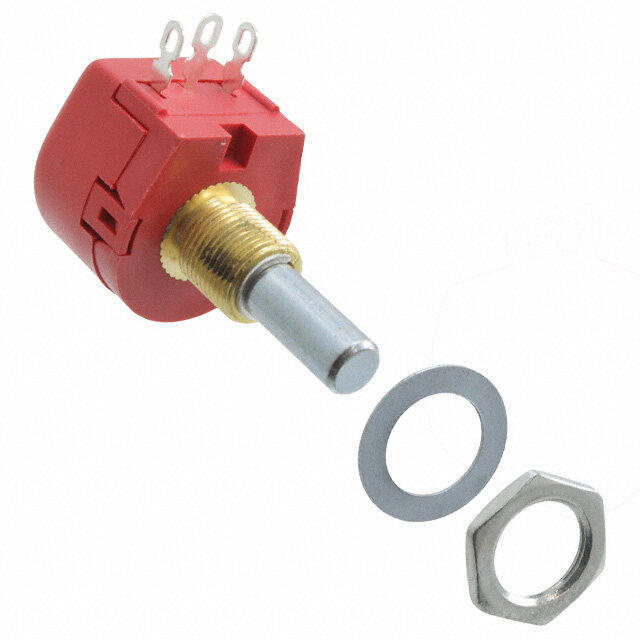
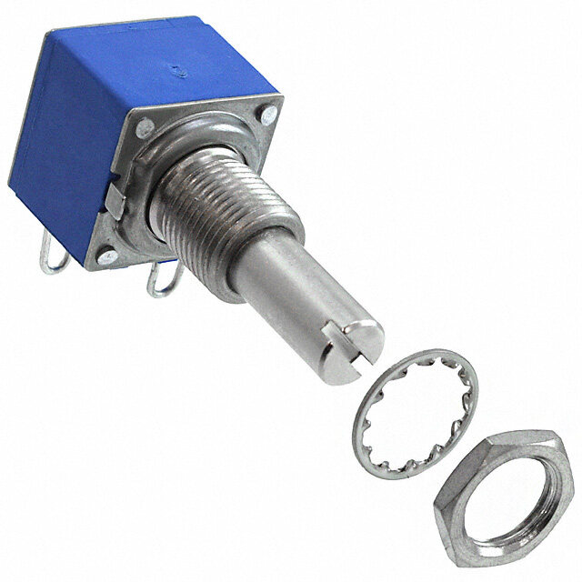
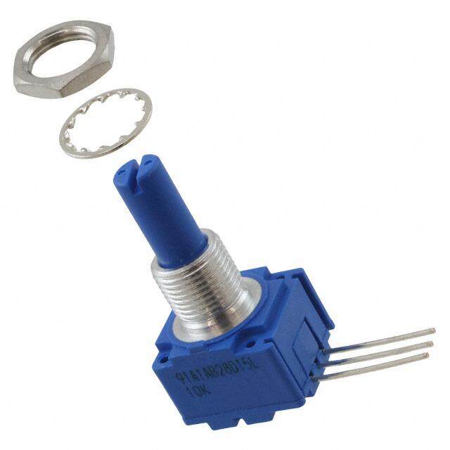
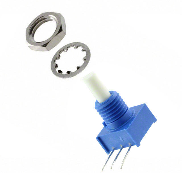
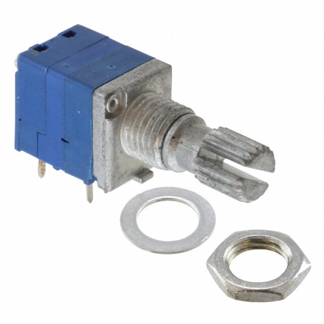
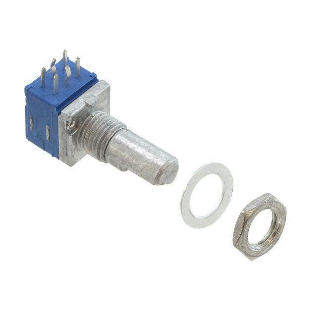
0.5 W Conductive Plastic Potentiometers 392 Series, RV6 Series Datasheet
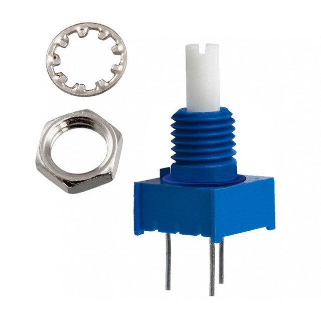
392 Series, RV6 Series 0.5 W Conductive Plastic Potentiometers Potentiometers convert rotary motion into a change of resistance, supplying a smooth transition of voltage or current levels. The resulting voltage output may be used to control position transducers in a wide variety of potential applications. The 392 Series and RV6 Series 0.5 W Plastic Potentiometers are economical devices designed to meet wave soldering process requirements for mounting to printed circuit boards (PCBs). All versions contain an internal shaft seal for moisture protection and comply with PCB washability test requirements and MIL-R-94 standards where appropriate. Termination types are PC pin or solder hook, both are solder-dipped. These small, single turn devices have a 3,18 mm [0.125 in] diameter shaft that is available in a range of lengths. Most configurations have either a standard or split locking 1/4-32 NEF-2A bushing in panel seal or no panel seal versions. The shaft/bushing materials are nickel-plated brass or thermoplastic. They are available in metal/metal, plastic/plastic, or a combination of the two. Custom designs are available upon request. The 392 Series and RV6 Series are available in resistances from 100 Ohm to 5 MOhm, inclusive. Tapers include linear, log, and antilog to meet a wide range of application requirements. RV6 Series devices meet requirements of MIL-R-94. Key Features and Benefits Potential Applications • Wave solderable: Allows the devices to be automatically INDUSTRIAL/COMMERCIAL soldered on a PCB using the wave soldering process instead • Audio and visual equipment (i.e., guitars, sound mixers, of being manually soldered, saving time and yielding consistent projectors) results • Light switches • PCB washable: Permits the PCB board containing the soldered • Hand-held equipment (e.g., multimeters and mobile devices to be washed after soldering, saving time and yielding monitoring devices) consistent results • Test and measurement equipment (e.g. oscilloscopes) • Cost-effective: Supplies good performance at a reasonable • Communications equipment (e.g. walkie-talkies) price • Thermostats • Wide range of resistance values (100 Ohm to 5 MOhm, MEDICAL inclusive): Promotes flexibility in the applications • Small package size: Allows use where space contraints may • Hand-held equipment (e.g., mobile monitoring devices) be present • Laboratory and diagnostic equipment , TRANSPORTATION Table of Contents • Vehicle manual controls (e.g. joysticks) General Specifications .................3-6 General Configuration Guide ..............7 392 Series: Specific Configurations .............. 8-10 Order Guides ......................11-21 RV6 Series: Specific Configurations ................22 Order Guides . . . . . . . . . . . . . . . . . . . . . 23-27 Mounting Hardware ............. back page Additional Information. . . . . . . . . . . . back page Wave solderable • Washable • Cost-effeCtive 2 sensing.honeywell.com
General Specifications Table 1. Electrical Specifications Parameter Characteristic 392 Series RV6 Series Maximum working voltage 350 Vdc max. Dielectric strength 750 Vac for 60 s at 1 mPa [atm], 350 Vac for 60 s at 11,5 kPa [3.4 inHg] Power rating: solder hook 0.5 W at 70 °C [158 °F], derated to 120 °C [248 °F] 0.25 W Taper linear (S), linear (special), log (Z), reverse log (RZ) linear (S), log (Z) CRV1: linear tapers 1.5% max. of total resistance log, reverse log tapers Resistance: linear tapers 100 Ohm to 5 MOhm 100 Ohm to 1 MOhm log, reverse log tapers 500 Ohm to 2 MOhm 500 Ohm to 1 MOhm Resistance tolerance: linear tapers: 100 Ohm to 1 MOhm ±10% >1 MOhm ±20% log, reverse log tapers: 500 Ohm to 250 kOhm ±10% >250 kOhm ±20% End resistance 4 Ohm max. at each end of rotation Linearity ±5% independent Electrical rotation: nominal 265° (+0°/-10°) effective 295° (±5°) 1Contact resistance variation is the maximum momentary change in contact resistance that occurs when the wiper is moved from one location to another location. The larger this change, the more difficult it is to set the trimmer potentiometer and the more unstable the long term setting will be. Wave solderable • Washable • Cost-effeCtive sensing.honeywell.com 3
General Specifications Table 2. Mechanical Specifications Parameter Characteristic 392 Series RV6 Series Shaft: diameter 3,18 mm [0.125 in] material: metal nickel-plated brass plastic thermoplastic Bushing: diameter/thread size 1/4-32 NEF-2A material: metal nickel-plated brass plastic thermoplastic Termination base material thermoset plastic Termination types: solder hook material brass, solder (tin-lead) dip finish PC pin: PCB fit 2,54 mm [0.100 in] grid spacing, 0,86 mm [0.034 in] holes material brass, solder (SAC305) dip finish Cover material stainless steel Housing material thermoplastic Base material thermoset Mounting hardware material: jam nut nickel-plated brass mounting nut nickel-plated brass lock washer nickel-plated phospher bronze panel O-ring Buna-N Sealant epoxy Operating torque 3,5 mN m to 14 mN m [0.5 in-oz to 2.0 in-oz] Stop torque 34 N m [3 in-lb] Weight (approx.): metal shaft and metal bushing 7,09 g [0.25 oz] plastic shaft and plastic bushing 2,84 g [0.1 oz] Table 3. Environmental Specifications Parameter Characteristic 392 Series RV6 Series Operating temperature -55 °C to 120 °C [-67 °F to 248 °F] Base material -40 °C to 120 °C [-40 °F to 248 °F] Rotational life tested to 50,000 cycles Soldering — MIL-R-94 Table 4. Maximum Percent Temporary Resistance from 25 °C [77 °F] Temperature Nominal Resistance -55 °C -40 °C 0 °C 25 °C 55 °C 85 °C 120 °C [-67 °F] [-40 °F] [32 °F] [77 °F] [131 °F] [185 °F] [248 °F] 100 Ohm ±5.0 ±4.0 ±1.5 0 ±1.5 ±2.0 ±3.5 10 kOhm +7.0 +5.5 +2.0 0 ±1.5 ±2.5 ±5.5 100 kOhm +8.0 +6.0 +2.5 0 ±2.0 ±3.5 ±6.0 1 MOhm +10.0 +8.0 +3.0 0 ±2.5 ±4.0 ±7.5 4 sensing.honeywell.com
General Specifications Figure 1. Power Derating Curve 100 90 80 70 %) r ( 60 e w o 50 P d e 40 at R 30 20 10 0 0 10 20 30 40 50 60 70 80 90 100 110 120 Temperature (°C) Figure 2. Recommended Wave Solder and Board Wash Parameters Wave solder Blow dry Wash Fluxing Preheat and Bake dry rinse 345 305 265 F) ° e ( 225 r u at r pe 185 m e T 145 105 65 0 1 2 3 4 5 6 7 8 Time (Minutes) Process Limits Temperature Time Preheat, max. 91 °C [195 °F] 1 min. Solder, max. 288 °C [550 °F] — Differential after solder in wash (3/4T), max. 22 °C [72 °F] — Wash 66 °C to 71 °C [150 °F to 160 °F] 1.5 min. Dry 47 °C to 104 °C [116 °F to 220 °F] 2 min. sensing.honeywell.com 5
General Specifications Figure 3. Electrical Taper Diagrams (For reference only.) Linear (S) The change in resistance is directly proportional to the Linear (Special) Attains 50% resistance value at 50% of clockwise degree of rotation (right-hand or left-hand). rotation (left-hand). 100 100 90 90 80 80 %) %) 70 70 e ( e ( c c n 60 n 60 a a st st si 50 si 50 e e R R al 40 al 40 ot ot T T 30 30 20 20 10 10 0 0 0 10 20 30 40 50 60 70 80 90 100 0 10 20 30 40 50 60 70 80 90 100 Angular Rotation, Clockwise Left to Right (%) Angular Rotation, Clockwise Left to Right (%) Log (Z) Attains 10% resistance value at 50% of clockwise rotation Reverse Log (RZ) Attains 10% resistance value at 50% of clockwise (left-hand). rotation (right-hand). 100 100 90 90 80 80 e (%) 70 e (%) 70 c c n 60 n 60 a a st st si 50 si 50 e e R R al 40 al 40 ot ot T T 30 30 20 20 10 10 0 0 0 10 20 30 40 50 60 70 80 90 100 0 10 20 30 40 50 60 70 80 90 100 Angular Rotation, Clockwise Left to Right (%) Angular Rotation, Clockwise Left to Right (%) Figure 4. Functional Schematic C (Center) CW (Clock-Wise) L (Left) R (Right) 6 sensing.honeywell.com
General Configuration Guide Figure 5. General Configuration Guide Fourth (XXJul14) This figure shows possible 392 Series and RV6 Series configurations. Not all combinations may be available, please contact Honeywell. See the Order Guides for each series on subsequent pages for currently available catalog listings. Resistance Number Electrical Signifi- of Zeros Taper and Anti-Rotation Product Bushing Shaft Shaft cant that Resistance (AR) Termination Series Type and Length Switch Type Length Digit Follow Tolerance Locating Pin Type 392 Series, Metal: None Metal: 9,53 mm [0.325]1 10 Ohm 0 Linear: No Solder RV6 Series 1/4-32 NEF-2A: ø3,18 mm [0.125 in]: 10% locating hook 0.5 W Panel seal: Flatted 12,7 mm [0.50 in]1 15 Ohm 1 20% pins Conductive Standard 15,88 mm [0.625 in] 20 Ohm 2 Linear special Plastic (6,35 mm [0.25 in]) Potentiometers 19,05 mm [0.75 in] 25 Ohm 3 Log: 22,23 mm [0.875 in] 50 Ohm 4 10% 20% One PC pin Round 31,75 mm [1.25 in] 5 Reverse Log: locating Split locking 50,8 mm [2.00 in] 10% pin (12,7 mm [0.50 in]) 20% 63,5 mm [2.50 in] Custom Custom Slotted 1Applies to 6,25 mm [0.25 in] Two bushings only. locating Custom pins No panel seal: Standard (6,25 mm [0.25 in]) Plastic: Custom ø3,18 mm [0.125 in]: Slotted Split locking General 392 Series, RV6 Series Terminology (12,7 mm [0.50 in]) Jam nut Mounting nut Custom Lock washer Unthreaded O-Ring Mounting (6,25 mm [0.25 in]) hardware Locating pin Shaft Plastic: Bushing 1/4-32 NEF-2A: Standard Termination Trimmer Custom sensing.honeywell.com 7
392 Series Specific Configurations Table 5. 392 Series Metal Shaft and Metal Bushing Specific Configurations Shaft Bushing AR Termin- Configuration with Shaft Bushing AR Termin- Configuration with Type Type Pin ation Associated Hardware Type Type Pin ation Associated Hardware 392-A (See Table 392-A on p. 11.) 392-B (See Table 392-B on p. 11.) panel no panel seal, 1 seal, 1 solder solder flatted standard, and round standard, and hook hook 6,35 mm 2 6,35 mm 2 [0.25 in] [0.25 in] 392-C (See Table 392-C on p. 12.) 392-D (See Table 392-D on p. 12.) no panel no panel seal, 1 seal, split, flatted and PC pin slotted standard, 1 PC pin locking, 2 6,35 mm 12,7 mm [0.25 in] [0.50 in] 392-E (See Table 392-E on p. 13.) 392-F (See Table 392-F on p 13.) no panel no panel seal, seal, flatted standard, 0 PC pin slotted standard, 1 PC pin 6,35 mm 6,35 mm [0.25 in] [0.25 in] 392-G (See Table 392-G on p. 14.) 392-H (See Table 392-H on p.14.) no panel no panel seal, seal, solder solder flatted standard, 1 slotted standard, 1 hook hook 6,35 mm 6,35 mm [0.25 in] [0.25 in] 392-I (See Table 392-I on p. 15.) 392-J (See Table 392-J on p.15.) no panel no panel seal, 1 seal, solder flatted, standard, and PC pin slotted standard, 0 hook 6,35 mm 2 6,35 mm [0.25 in] [0.25 in] 8 sensing.honeywell.com
392 Series Specific Configurations Table 5. 392 Series Metal Shaft and Metal Bushing Specific Configurations (continued) Shaft Bushing AR Termin- Configuration with Shaft Bushing AR Termin- Configuration with Type Type Pin ation Associated Hardware Type Type Pin ation Associated Hardware 392-K (See Table 392-K on p. 16.) 392-L (See Table 392-L on p. 17.) no panel no panel seal, 1 seal, solder slotted standard, and PC pin slotted standard, 0 hook 6,35 mm 2 6,35 mm [0.25 in] [0.25 in] 392-M (See Table 392-M on p. 17.) 392-N (See Table 392-N on p. 18.) no panel no panel seal, 1 seal, 1 un- slotted and PC pin slotted standard, and PC pin threaded, 2 6,35 mm 2 6,35 mm [0.25 in] [0.25 in] 392-O (See Table 392-O on p. 18.) 392-P (See Table 392-P on p. 18.) no panel no panel seal, 1 seal, 1 solder slotted standard, and slotted standard, and PC pin hook 6,35 mm 2 6,35 mm 2 [0.25 in] [0.25 in] sensing.honeywell.com 9
392 Series Specific Configurations Table 5. 392 Series Plastic Shaft and Plastic Bushing Specific Configurations Shaft Bushing AR Termin- Configuration with Shaft Bushing AR Termin- Configuration with Type Type Pin ation Associated Hardware Type Type Pin ation Associated Hardware 392-Q (See Table 392-Q on p. 19.) 392-R (See Table 392-R on p 20.) no panel seal, standard, solder slotted 2 6,35 mm hook [0.25 in] no panel length seal, standard, 392-S (See Table 392-S on p. 21.) slotted 0 PC pin 6,35 mm [0.25 in] length trimmer, slotted 0 PC pin standard 10 sensing.honeywell.com
392 Series Order Guides Table 392-A Order Guide Electrical Dimensions Catalog A B C D RoHS Mounting Resistance Listing Resistance Flat Flat Shaft Bushing Compliant Hardware Tolerance Taper (Ohm) Length Width Length Length (±%) (mm [in]) (mm [in]) (mm [in]) (mm [in]) 4,78 2,39 12,70 6,35 392074M8792 10 k 10 S yes unassembled [0.188] [0.094] [0.500] [0.250] Dimensional Drawing (For reference only: mm [in].) 16,66 Max. C [0.656] Shown with 50% shaft rotation 3,97 Typ. 0,91 Max. 2 [0.156] [0.036] ø13,08 Center 11,51 D A [0.515] 1,57 [0.453] 2,03 Typ. [0.062] B [0.080] 6,46 5,08 [0.254] [0.200] 3X 2,24 Typ. [0.088] ø3,18 1 [0.125] 45° 3 Left 1/4-32 NEF-2A Locating 90° Right pin 1 5,08 Mounting surface [0.200] 2X 0,64 [0.025] Locating pin 2 Table 392-B Order Guide Electrical Dimensions Catalog A B RoHS Mounting Resistance Listing Resistance Shaft Bushing Compliant Hardware Tolerance Taper (Ohm) Length Length (±%) (mm [in]) (mm [in]) 15,09 6,35 392063M9270 10 k 10 S yes unassembled [0.594] [0.250] Dimensional Drawing (For reference only: mm [in].) 16,66 Max. [0.656] A Shown with 50% shaft rotation 3,97 Typ. [0.156] 0,89 Max. ø13,08 2 1,57 [0.035] [0.515] Center [0.062] 11,51 B [0.453] 2,03 Typ. 3X 2,24 Typ. [0.080] [0.088] 6,46 [0.254] 5,08 [0.200] ø3,17 Lo pciant i1ng 1 [0.125] 45° 3 Left 1/4-32 NEF-2A Right 5,08 Mounting surface [0.200] 2X 0,89 Locating [0.035] pin 2 sensing.honeywell.com 11
392 Series Order Guides Table 392-C Order Guide Electrical Dimensions Catalog A B C D E RoHS Mounting Resistance Listing Resistance Flat Flat Shaft Bushing Termination Compliant Hardware Tolerance Taper (Ohm) Length Width Length Length Length (±%) (mm [in]) (mm [in]) (mm [in]) (mm [in]) (mm [in]) 5,16 2,39 18,26 12,70 14,30 392050M7461 2.5 M 10 S yes unassembled [0.203] [0.094] [0.719] [0.500] [0.563] Dimensional Drawing (For reference only: mm [in].) 26,59 C [1.047] Shown with 50% shaft rotation 0,89 Max. [0.035] ø13,08 2 [01.,05672] E [ 01.14,6991] Max. D A [0.515] Center B 2,03 Typ. [0.080] 1,02 5,08 [0.040] [0.200] ø3,18 Locating [0.125] pin 1 45° Ri3ght L1eft 3X ø0,71 1/4-32 NEF-2A 90° [05.,20080] [0.028] 2X 0,89 Mounting surface [0.035] Locating pin 2 Table 392-D Order Guide Electrical Dimensions Catalog A B C D E RoHS Mounting Resistance Listing Resistance Slot Slot Shaft Bushing Termination Compliant Hardware Tolerance Taper (Ohm) Depth Width Length Length Length (±%) (mm [in]) (mm [in]) (mm [in]) (mm [in]) (mm [in]) 0,79 0,79 12,70 6,35 14,30 392050M8789 10 k 10 RZ yes unassembled [0.031] [0.031] [0.500] [0.250] [0.563] Dimensional Drawing (For reference only: mm [in].) 26,59 C Shown with 50% shaft rotation [1.047] 0,89 Max. [0.035] ø13,08 11,91 Max. [0.515] 2 E [0.469] D A 2,03 Typ. B Center 1,57 [0.080] [0.062] ø3,18 [0.125] 6,46 [0.254] 5,08 [0.200] Locating 3 1 1/4-32 NEF-2A pin 1 90° 45° Right Left 3X ø0,71 5,08 [0.028] Mounting surface [0.200] 0,89 [0.035] 12 sensing.honeywell.com
392 Series Order Guides Table 392-E Order Guide Electrical Dimensions Catalog A B C D E RoHS Mounting Resistance Listing Resistance Flat Flat Shaft Bushing Termination Compliant Hardware Tolerance Taper (Ohm) Length Width Length Length Length (±%) (mm [in]) (mm [in]) (mm [in]) (mm [in]) (mm [in]) 7,14 2,36 14,27 4,75 14,30 392050M9605 2.5 k 10 S yes unassembled [0.281] [0.093] [0.562] [0.187] [0.563] Dimensional Drawing (For reference only: mm [in].) 26,59 C Ce2nter [01.,05672] [1.04 7 ] 0,89 Max. Shown with 50% shaft rotation [0.035] ø13,08 E 11,91 Max. D A [0.515] [0.469] 2,03 Typ. 5,08 [0.080] [0.200] B 6,46 3 1 [0.254] Right Left [05.,20080] ø3,18 [0.125] 45° 3X ø0,71 1/4-32 NEF-2A 90° [0.028] Mounting surface Table 392-F Order Guide Electrical Dimensions Catalog A B C D E RoHS Mounting Resistance Listing Resistance Slot Slot Shaft Bushing Termination Compliant Hardware Tolerance Taper (Ohm) Depth Width Length Length Length (±%) (mm [in]) (mm [in]) (mm [in]) (mm [in]) (mm [in]) 0,79 0,79 12,70 6,35 14,30 392050234617001 10 k 10 RZ no unassembled [0.031] [0.031] [0.500] [0.250] [0.563] Dimensional Drawing (For reference only: mm [in].) 26,59 C Shown with 50% shaft rotation [1.047] 0,89 Max. [0.035] ø13,08 Ce2nter [01.,05672] E [ 01.14,6991] Max. D A 2,03 Typ. [0.515] B [0.080] ø3,18 [0.125] 6,46 [0.254] 5,08 [0.200] Ri3ght L1eft 3 X [ø00.0,7218] 1/4-32 NEF-2A Lo pciant i1ng 90° 45° 5,08 Mounting surface [0.200] 2X 0,89 Locating [0.035] pin 2 sensing.honeywell.com 13
392 Series Order Guides Table 392-G Order Guide Electrical Dimensions Catalog A B C D RoHS Mounting Resistance Listing Resistance Flat Flat Shaft Bushing Compliant Hardware Tolerance Taper (Ohm) Length Width Length Length (±%) (mm [in]) (mm [in]) (mm [in]) (mm [in]) 6,35 2,39 41,28 6,35 392063M9549 15 k 10 special yes unassembled [0.250] [0.094] [1.625] [0.250] Dimensional Drawings (For reference only: mm [in].) 16,66 Max. C Shown with 50% shaft rotation [0.656] 3,97 Typ. 0,89 Max. 2,03 Typ. [0.156] [0.035] [0.080] Ce2nter [01.,05672] [ 01.14,5531] Max. D A ø [103.5,0185] 6,46 B [0.254] 5,08 [0.200] 45° Ri3ght L1eft 1/4-32 NEF -2A ø[03.1,1285] 90° 5,08 3X 2,24 Typ. Mounting surface [0.200] [0.088] Locating 0,89 pin 1 [0.035] Table 392-H Order Guide Electrical Dimensions Catalog A B C D RoHS Mounting Resistance Listing Resistance Slot Slot Shaft Bushing Compliant Hardware Tolerance Taper (Ohm) Depth Width Length Length (±%) (mm [in]) (mm [in]) (mm [in]) (mm [in]) 0,79 0,79 12,70 6,35 392101M9437 2.5 k 10 S yes unassembled [0.031] [0.031] [0.500] [0.250] Dimensional Drawing (For reference only: mm [in].) [ 01.66,5666] Max. C Shown with 50% shaft rotation [ 0 3.1,5967] Typ. [ 0 0.0,8395 ]Max. ø13,08 2 [0.515] Center [ 01.14,9531] Max. D A B 1,57 3X 2,24 Typ. 2,03 Typ. [0.062] [0.088] ø3,18 [0.080] [0.125] 6,46 5,08 [0.254] [0.200] 1 Locating 45° 3 Left 1/4-32 NEF-2A pin 1 90° Right 5,08 Mounting surface [0.200] 2X 0,99 [0.039] Locating pin 2 14 sensing.honeywell.com
392 Series Order Guides Table 392-I Order Guide Electrical Dimensions Catalog A B C D E RoHS Mounting Resistance Listing Resistance Flat Flat Shaft Bushing Termination Compliant Hardware Tolerance Taper (Ohm) Length Width Length Length Length (±%) (mm [in]) (mm [in]) (mm [in]) (mm [in]) (mm [in]) 11,91 2,39 19,05 6,35 14,30 392050M9173 10 k 10 Z yes unassembled [0.469] [0.094] [0.750] [0.250] [0.563] 15,47 2,39 22,23 6,35 14,30 392050M9514 10 k 10 Z yes unassembled [0.609] [0.094] [0.875] [0.250] [0.563] Dimensional Drawing (For reference only: mm [in].) Shown with 50% shaft rotation 26,59 C [1.047] 11,91 Max. ø13,08 [0.469] [0.515] Ce2nter [01.,05672] E [ 0 0.0,8395 ]Max. D A 0,94 2,03 Typ. [0.037] [0.080] B 5,08 [0.200] 3 1 ø3,18 Lo pciant i1ng 45° Right Left 1/4-32 NEF-2A [0.125] 90° 5,08 3X ø0,71 [0.200] [0.028] Mounting surface 2X 0,89 Locating [0.035] pin 2 Table 392-J Order Guide Electrical Dimensions Catalog A B C D RoHS Mounting Resistance Listing Resistance Slot Slot Shaft Bushing Compliant Hardware Tolerance Taper (Ohm) Depth Width Length Length (±%) (mm [in]) (mm [in]) (mm [in]) (mm [in]) 0,79 0,79 14,68 6,35 392063M9038 25 k 10 S yes unassembled [0.031] [0.031] [0.578] [0.250] Dimensional Drawing (For reference only: mm [in].) 2 Center [01.,05672] [ 01.66,5666] Max. C Shown with 50% shaft rotation 3,97 Typ. [0.156] 0,89 Max. ø13,08 [0.035] [0.515] [ 011.4,5513] D A 2,03 Typ. B 5,08 [0.080] [0.200] 3X 2,24 Typ. ø3,18 [0.088] [0.125] Ri3ght L1eft [06.2,4564] 5,08 [0.200] 45° 1/4-32 NEF-2A 90° Mounting surface sensing.honeywell.com 15
392 Series Order Guides Table 392-K Order Guide Electrical Dimensions Catalog A B C D E RoHS Mounting Resistance Listing Resistance Slot Slot Shaft Bushing Termination Compliant Hardware Tolerance Taper (Ohm) Depth Width Length Length Length (±%) (mm [in]) (mm [in]) (mm [in]) (mm [in]) (mm [in]) 0,79 0,79 22,23 6,35 14,30 392JA2.5MEG 2.5 M 20 S no unassembled [0.031] [0.031] [0.875] [0.250] [0.563] 0,79 0,79 22,23 6,35 14,30 392JA250 250 10 S yes unassembled [0.031] [0.031] [0.875] [0.250] [0.563] 0,79 0,79 22,23 6,35 14,30 392JA2500 2.5 k 10 S yes unassembled [0.031] [0.031] [0.875] [0.250] [0.563] 0,79 0,79 22,23 6,35 14,30 392JA5MEG 5 M 20 S yes unassembled [0.031] [0.031] [0.875] [0.250] [0.563] 0,79 0,79 22,23 6,35 14,30 392JA1MEG 1 M 20 S yes unassembled [0.031] [0.031] [0.875] [0.250] [0.563] 0,79 0,79 22,23 6,35 14,30 392JA100 100 10 S yes unassembled [0.031] [0.031] [0.875] [0.250] [0.563] 0,79 0,79 22,23 6,35 14,30 392JA100K 100 k 10 S yes unassembled [0.031] [0.031] [0.875] [0.250] [0.563] 0,79 0,79 22,23 6,35 14,30 392JA10K 10 k 10 S yes unassembled [0.031] [0.031] [0.875] [0.250] [0.563] 0,79 0,79 22,23 6,35 14,30 392JA1K 1 k 10 S yes unassembled [0.031] [0.031] [0.875] [0.250] [0.563] 0,79 0,79 22,23 6,35 14,30 392JA250K 250 k 10 S yes unassembled [0.031] [0.031] [0.875] [0.250] [0.563] 0,79 0,79 22,23 6,35 14,30 392JA25K 25 k 10 S yes unassembled [0.031] [0.031] [0.875] [0.250] [0.563] 0,79 0,79 22,23 6,35 14,30 392JA500K 500 k 10 S yes unassembled [0.031] [0.031] [0.875] [0.250] [0.563] 0,79 0,79 22,23 6,35 14,30 392JA50K 50 k 10 S yes unassembled [0.031] [0.031] [0.875] [0.250] [0.563] 0,79 0,79 22,23 6,35 14,30 392JA5K 5 k 10 S yes unassembled [0.031] [0.031] [0.875] [0.250] [0.563] 0,79 0,79 15,88 6,35 14,30 392050M8964 50 k 20 S yes unassembled [0.031] [0.031] [0.625] [0.250] [0.563] 0,79 0,79 15,09 6,35 14,30 392050M9492 5 k 10 S yes unassembled [0.031] [0.031] [0.594] [0.250] [0.563] 0,79 0,79 25,40 6,35 14,30 392050M9519 50 k 20 S yes unassembled [0.031] [0.031] [1.00] [0.250] [0.563] 0,79 0,79 22,23 6,35 9.53 392050M0016 10 k 10 S no unassembled [0.031] [0.031] [0.875] [0.250] [0.375] 0,79 0,79 15,88 6,35 14,30 392050M8715 2 k 20 S yes unassembled [0.031] [0.031] [0.625] [0.250] [0.563] Dimensional Drawing (For reference only: mm [in].) 26,59 C [1.047] Shown with 50% shaft rotation 0.89 Max. [0.035] ø13,08 [01.,05672] E [101.4,9619 ]Max. D A 2,03 Typ. [0.515]B 2 [0.080] Center 6,46 [0.254] 5,08 [0.200] 1/4-32 NEF-2A ø[03.1,1285] Lo pciant i1ng 45° 90° Ri3ght L1eft 3 X [ø00.0,7218] 2X 0,99 Mounting surface 5,08 Locating [0.039] [0.200] pin 2 16 sensing.honeywell.com
392 Series Order Guides Table 392-L Order Guide Electrical Dimensions Catalog A B C D RoHS Mounting Resistance Listing Resistance Slot Slot Shaft Bushing Compliant Hardware Tolerance Taper (Ohm) Depth Width Length Length (±%) (mm [in]) (mm [in]) mm [in] mm [in] 0,79 0,79 15,88 6,35 392101M9524 100 10 S yes unassembled [0.031] [0.031] [0.625] [0.250] Dimensional Drawing (For reference only: mm [in].) Ce2nter [106.6,6566 ]Max. C Shown with 50% shaft rotation 1,57 [0.062] 3,97 Typ. 0,89 Max. [0.156] [0.035] ø13,08 [0.515] [101.4,5513 ]Max. D A A 5,08 3X 2,24 Typ. 2,03 Typ. [0.200] [0.088] ø3,17 [0.080] [0.125] 1 6,46 3 Left [0.254] Right 5,08 [0.200] 45° 1/4-2 NEF-2A 90° Mounting surface Table 392-M Order Guide Electrical Dimensions Catalog A B C D E RoHS Mounting Resistance Listing Resistance Slot Slot Shaft Bushing Termination Compliant Hardware Tolerance Taper (Ohm) Depth Width Length Length Length (±%) (mm [in]) (mm [in]) (mm [in]) (mm [in]) (mm [in]) 0,79 0,79 25,40 6,35 14,30 392050M9012 2 k 10 S yes unassembled [0.031] [0.031] [1.000] [0.250] [0.563] Dimensional Drawing (For reference only: mm [in].) 26,59 C [1.047] Shown with 50% shaft rotation 0.89 Max. [0.035] ø13,08 Ce2nter [01.,05672] E [101.4,9619 ]Max. D A [0.515] B 2,03 Typ. [0.080] 6,46 5,08 [0.254] [0.200] ø3,18 3 1 [0.125] 45° Right 5,08 Left 3X ø0,71 Mounting surface Locating 90° [0.200] [0.028] 2X 0,89 pin 1 [0.035] Locating pin 2 sensing.honeywell.com 17
392 Series Order Guides Table 392-N Order Guide Electrical Dimensions Catalog A B C D E RoHS Mounting Resistance Listing Resistance Slot Slot Shaft Bushing Termination Compliant Hardware Tolerance Taper (Ohm) Depth Width Length Length Length (±%) (mm [in]) (mm [in]) (mm [in]) (mm [in]) (mm [in]) 0,79 0,79 22,23 6,35 14,30 392050M8756 10 k 10 Z no unassembled [0.031] [0.031] [0.875] [0.250] [0.563] 0,79 0,79 17,45 7,92 14,30 392050M9382 500 10 Z yes unassembled [0.031] [0.031] [0.687] [0.312 [0.563] 0,79 0,79 15,09 6,35 14,30 392050M9488 1 M 20 Z yes unassembled [0.031] [0.031] [0.594] [0.250] [0.563] Dimensional Drawing (For reference only: mm [in].) 26,59 C [1.047] Shown with 50% shaft rotation 0.89 Max. [0.035] ø13,08 1,57 Ce2nter [0.062] E [101.4,9619 ]Max. D A [0.515]B 2,03 Typ. [0.080] 5,08 6,46 [0.200] [0.254] ø3,17 Ri3ght 5,08 L1eft 3X ø0,71 1/4-32 NEF-2A [0.125] Lo pciant i1ng 90° 45° [0.200] [0.028] 2X 0,89 Mounting surface [0.035] Locating pin 2 Table 392-O Order Guide Electrical Dimensions Catalog A B C D RoHS Mounting Resistance Listing Resistance Slot Slot Shaft Bushing Compliant Hardware Tolerance Taper (Ohm) Depth Width Length Length (±%) (mm [in]) (mm [in]) (mm [in]) (mm [in]) 0,79 0,79 15,88 6,35 392063M9308 10 k 10 S yes unassembled [0.031] [0.031] [0.625] [0.250] Dimensional Drawing (For reference only: mm [in].) 16,66 Max. C [0.656] Shown with 50% shaft rotation 0,89 Max. 3,18 [0.035] [0.125] ø13,08 Ce2nter 1,57 [ 03.,19576 M] ax. [101.4,5513 ]Max. D [04.,17888] [0.515] B [0.062] 2,03 Typ. 3X 2,24 Typ. 6,46 [0.088] B [0.080] [0.254] 5,08 [0.200] ø3,17 1 [0.125] Locating 45° 3 Left 1/4-32 NEF-2A pin 1 90° Right 5,08 Mounting surface [0.200] 2X 0,99 [0.039] Locating pin 2 18 sensing.honeywell.com
392 Series Order Guides Table 392-P Order Guide Electrical Dimensions Catalog A B C D E RoHS Mounting Resistance Listing Resistance Slot Slot Shaft Bushing Termination Compliant Hardware Tolerance Taper (Ohm) Depth Width Length Length Length (±%) (mm [in]) (mm [in]) (mm [in]) (mm [in]) (mm [in]) 0,79 0,79 12,70 6,35 14,30 392NAYSB103A 10 k 10 S no unassembled [0.031] [0.031] [0.500] [0.250] [0.563] Dimensional Drawing (For reference only: mm [in].) 26,59 Max. Shown with 50% shaft rotation [1.047] C 0,89 Max. ø13,08 2 1,57 [0.035] [0.515] Center [0.062] E 11,91 D A [0.469] 2,03 Typ. [0.080] ø3,18 [0.125] 6,46 [0.254] 5,08 [0.200] 3 1 1/4-32 NEF-2A Locating 45° Right Left 3X ø0,71 pin 1 90° [0.028] Mounting surface 5,08 2X 0,89 [0.200] [0.035] Locating pin 2 Table 392-Q Order Guide Electrical Dimensions Catalog A B C D RoHS Mounting Resistance Listing Resistance Slot Slot Shaft Bushing Compliant Hardware Tolerance Taper (Ohm) Depth Width Length Length (±%) (mm [in]) (mm [in]) (mm [in]) (mm [in]) 0,79 0,79 9,53 6,35 392072M6256 5 k 10 S yes unassembled [0.031] [0.031] [0.375] [0.250] Dimensional Drawing (For reference only: mm [in].) 16,66 Max. C [0.656] Shown with 50% shaft rotation 3,97 Max. 0,92 Max. [0.156] [0.036] ø13,08 2 [0.515] Center [01.,05672] [101.4,5513 ]Max. D A 2,03 Typ. B [0.080] 3X 2,24 Typ. [0.088] 6,45 [0.254] 5,08 [0.200] ø3,16 [0.125] Locating 1 pin 1 45° 3 Left 1/4-32 NEF-2A Right 90° 5,08 Mounting surface [0.200] 2X 0,89 [0.035] Locating pin 2 sensing.honeywell.com 19
392 Series Order Guides Table 392-R Order Guide Electrical Dimensions Catalog A B C D E RoHS Mounting Resistance Listing Resistance Slot Slot Shaft Bushing Termination Compliant Hardware Tolerance Taper (Ohm) Depth Width Length Length Length (±%) (mm [in]) (mm [in]) (mm [in]) (mm [in]) (mm [in]) 0,79 0,79 22,23 6,35 14,30 392JB1MEG 1 M 20 S yes unassembled [0.031] [0.031] [0.875] [0.250] [0.563] 0,79 0,79 22,23 6,35 14,30 392JB100 100 10 S yes unassembled [0.031] [0.031] [0.875] [0.250] [0.563] 0,79 0,79 22,23 6,35 14,30 392JB100/NEW 100 10 S no unassembled [0.031] [0.031] [0.875] [0.250] [0.563] 0,79 0,79 22,23 6,35 14,30 392JB100K 100 k 10 S yes unassembled [0.031] [0.031] [0.875] [0.250] [0.563] 0,79 0,79 22,23 6,35 14,30 392JB10K 10 k 10 S yes unassembled [0.031] [0.031] [0.875] [0.250] [0.563] 0,79 0,79 22,23 6,35 14,30 392JB1K 1 k 10 S yes unassembled [0.031] [0.031] [0.875] [0.250] [0.563] 0,79 0,79 22,23 6,35 14,30 392JB250 250 10 S yes unassembled [0.031] [0.031] [0.875] [0.250] [0.563] 0,79 0,79 22,23 6,35 14,30 392JB2500 2.5 k 10 S yes unassembled [0.031] [0.031] [0.875] [0.250] [0.563] 0,79 0,79 22,23 6,35 14,30 392JB250K 250 k 10 S yes unassembled [0.031] [0.031] [0.875] [0.250] [0.563] 0,79 0,79 22,23 6,35 14,30 392JB25K 25 k 10 S yes unassembled [0.031] [0.031] [0.875] [0.250] [0.563] 0,79 0,79 22,23 6,35 14,30 392JB500 500 10 S yes unassembled [0.031] [0.031] [0.875] [0.250] [0.563] 0,79 0,79 22,23 6,35 14,30 392JB500K 500 k 10 S yes unassembled [0.031] [0.031] [0.875] [0.250] [0.563] 0,79 0,79 22,23 6,35 14,30 392JB50K 50 k 10 S yes unassembled [0.031] [0.031] [0.875] [0.250] [0.563] 0,79 0,79 22,23 6,35 14,30 392JB5K 5 k 10 S yes unassembled [0.031] [0.031] [0.875] [0.250] [0.563] 0,79 0,79 22,23 6,35 14,30 392051M9692 10 k 10 S yes none [0.031] [0.031] [0.875] [0.250] [0.563] 0,79 0,79 22,23 6,35 14,30 392051M9693 1 M 20 S yes none [0.031] [0.031] [0.875] [0.250] [0.563] 0,79 0,79 15,85 6,35 14,30 392051M5761 2.5 k 10 S yes none [0.031] [0.031] [0.624] [0.250] [0.563] 0,79 0,79 15,85 6,35 14,30 392051M5803 1 M 10 S yes unassembled [0.031] [0.031] [0.624] [0.250] [0.563] Dimensional Drawing (For reference only: mm [in].) 26,59 C [1.047] Shown with 50% shaft rotation 0.92 Max. ø13,03 [0.036] [0.513] E [101.4,9619 ]Max. D A B 2 1,57 Center [0.062] 2,03 Typ. [0.080] 6,44 [0.253] 5,08 [0.200] ø3,16 [0.125] Locating 45° 1/4-32 NEF-2A pin 1 3 1 3X ø0,71 90° Right Left [0.028] Mounting surface 5,08 2X 0,89 [0.200] [0.035] Locating pin 2 20 sensing.honeywell.com
392 Series Order Guides Table 392-S Order Guide Electrical Dimensions Catalog A B C RoHS Mounting Resistance Listing Resistance Slot Slot Termination Compliant Hardware Tolerance Taper (Ohm) Depth Width Length (±%) (mm [in]) (mm [in]) (mm [in]) 0,79 0,79 14,30 3925100K 100 k 10 S yes none [0.031] [0.031] [0.563] 0,79 0,79 14,30 392510K 10 k 10 S yes none [0.031] [0.031] [0.563] 0,79 0,79 14,30 3925250 250 10 S yes none [0.031] [0.031] [0.563] 0,79 0,79 14,30 3925500 500 10 S yes none [0.031] [0.031] [0.563] 0,79 0,79 14,30 3925500K 500 k 10 S yes none [0.031] [0.031] [0.563] 0,79 0,79 14,30 392550K 50 k 10 S yes none [0.031] [0.031] [0.563] 0,79 0,79 14,30 39255K 5 k 10 S yes none [0.031] [0.031] [0.563] 0,79 0,79 14,30 392055M8814 100 k 10 S yes none [0.031] [0.031] [0.563] Dimensional Drawing (For reference only: mm [in].) 26,59 [1.047] Shown with 50% shaft rotation A 0.92 Max. [0.036] ø13,03 [0.513] C 11.91 Max. 2 1,57 [0.469] A Center [0.062] See Detail A ø3,16 [0.125] 6,52 [0.257] 5,08 [0.200] Detail A 3 1 3X ø0,71 Mounting surface 90° Right Left [0.028] 5,08 [0.200] sensing.honeywell.com 21
RV6 Series Specific Configurations Table 7. RV6 Series Metal Shaft and Metal Bushing Specific Configurations Shaft Bushing AR Termin- Configuration with Shaft Bushing AR Termin- Configuration with Type Type Pin ation Associated Hardware Type Type Pin ation Associated Hardware RV6-A (See Table RV6-A on p. 23.) RV6-B (See Table RV6-B on p. 23.) panel no panel seal, 1 seal, 1 standard, solder solder flatted and flatted standard, and 6,35 mm hook hook 2 6,35 mm 2 [0.25 in] [0.25 in] RV6-C (See Table RV6-C on p. 24.) RV6-D (See Table RV6-D on p. 24.) panel seal, panel split 1 seal, 1 solder solder slotted locking, and slotted standard, and hook hook 12,7 mm 2 6,35 mm 2 [0.50 in] [0.25 in] RV6-E (See Table RV6-E on p. 25.) RV6-F (See Table RV6-F on pp. 26-27.) panel no panel seal, seal, split 1 1 solder standard, solder slotted locking, and slotted and hook 6,35 mm hook 12,7 mm 2 2 [0.25 in] [0.50 in] RV6-G (See Table RV6-G on p 27.) no panel seal, 1 standard, solder slotted and 6,35 mm hook 2 [0.25 in] 22 sensing.honeywell.com
RV6 Series Order Guides Table RV6-A Order Guide Electrical Dimensions Catalog A B C D RoHS Mounting Resistance Listing Resistance Flat Flat Shaft Bushing Compliant Hardware Tolerance Taper (Ohm) Length Width Length Length (±%) (mm [in]) (mm [in]) (mm [in]) (mm [in]) 15,47 2,39 22,23 6,35 RV6SAYFD502B 5 k 20 S no unassembled [0.609] [0.094] [0.875] [0.250] Dimensional Drawing (For reference only: mm [in].) 16,66 Max. C [0.656] Shown with 50% shaft rotation 3,97 Typ. 0,91 Max. 2 [0.156] [0.036] ø13,08 Center [01.,05672 ] 3 X[0 2.0,2848 ]Typ. [ 011.4,5513] D A B 2,03 Typ. [0.515] [0.080] 6,46 [0.254] 5,08 [0.200] Locating 1 ø3,18 pin 1 45° 3 Left 1/4-32 NEF-2A [0.125] 90° Right 5,08 [0.200] 2X 0,64 Mounting surface [0.025] Locating pin 2 Table RV6-B Order Guide Electrical Dimensions Catalog A B C D RoHS Mounting Resistance Listing Resistance Flat Flat Shaft Bushing Compliant Hardware Tolerance Taper (Ohm) Length Width Length Length (±%) (mm [in]) (mm [in]) (mm [in]) (mm [in]) 15,47 2,39 22,23 6,35 RV6NAYFD103A 10 k 10 S no unassembled [0.609] [0.094] [0.875] [0.250] Dimensional Drawing (For reference only: mm [in].) 16,66 Max. C [0.656] Shown with 50% shaft rotation 3,97 Typ. 0,89 Max. 2 [0.156] [0.035] ø13,08 Center 1,57 3X 2,24 Typ. [ 011.4,5513] D A B [0.515] [0.062] [0.088] 2,03 Typ. [0.080] 6,46 [0.254] 5,08 [0.200] Locating pin 1 1 ø3,18 45° Ri3ght Left 1/4-32 NEF-2A [0.125] 90° 5,08 [0.200] 2X 0,89 Mounting surface [0.035] Locating pin 2 sensing.honeywell.com 23
RV6 Series Order Guides Table RV6-C Order Guide Electrical Dimensions Catalog A B C D RoHS Mounting Resistance Listing Resistance Slot Slot Shaft Bushing Compliant Hardware Tolerance Taper (Ohm) Depth Width Length Length (±%) (mm [in]) (mm [in]) (mm [in]) (mm [in]) 0,79 0,79 15,88 12,70 RV6TAYSA103A 10 k 10 S no unassembled [0.031] [0.031] [0.625] [0.500] 0,79 0,79 15,88 12,70 RV6TAYSA503A 50 k 10 S no unassembled [0.031] [0.031] [0.625] [0.500] 0,79 0,79 22,23 12,70 RV6TAYSD103A 10 k 10 S no unassembled [0.031] [0.031] [0.875] [0.500] 0,79 0,79 22,23 12,70 RV6TAYSD502B 5 k 20 S no unassembled [0.031] [0.031] [0.875] [0.500] Dimensional Drawing (For reference only: mm [in].) 16,66 Max. Shown with 50% shaft rotation C [0.656] 2 1,57 3,97 Typ. 0,91 Max. ø13,08 Center [0.062] [0.156] [0.036] [0.515] 3X 2,24 Typ. 11,51 D A B [0.088] [ 0.453] 2,03 Typ. [0.080] ø3,18 [0.125] 5,08 6,54 [0.200] [0.258] Ri3ght L1eft Lo pciant i1ng 45° 5,08 1/4-32 NEF-2A 90° [0.200] Mounting surface 2X 0,89 Typ. Locating [0.035] pin 2 Table RV6-D Order Guide Electrical Dimensions Catalog A B C D RoHS Mounting Resistance Listing Resistance Slot Slot Shaft Bushing Compliant Hardware Tolerance Taper (Ohm) Depth Width Length Length (±%) (mm [in]) (mm [in]) (mm [in]) (mm [in]) 0,79 0,79 15,88 12,70 RV6SAYSA103A 10 k 10 S no unassembled [0.031] [0.031] [0.625] [0.500] 0,79 0,79 22,23 12,70 RV6SAYSA104A 100 k 10 S no unassembled [0.031] [0.031] [0.875] [0.500] 0,79 0,79 22,23 12,70 RV6SAYSD251A 250 k 10 S no unassembled [0.031] [0.031] [0.875] [0.500] RV6SAYSD502A 0,79 0,79 22,23 12,70 5 k 10 S no unassembled N/P 392 [0.031] [0.031] [0.875] [0.500] Dimensional Drawing (For reference only: mm [in].) Shown with 50% shaft rotation 2 16,66 Max. C Center [0.656] 1,57 [ 0 3.1,9576 ]Typ. [ 0 0.0,9316 ]Max. ø [103.5,0185] [0.062 ] 3X 2,24 Typ. [ 011.4,5513] D A [ 0 2.0,0830 ]Typ. B [0.088] 5,08 ø3,18 [0.200] [0.125] 6,46 1 [0.254] 3 Left Right 5,08 Locating 45° [0.200] pin 1 1/4-32 NEF-2A 90° Mounting surface 2X 0,64 [0.025] 24 sensing.honeywell.com
RV6 Series Order Guides Table RV6-E Order Guide Electrical Dimensions Catalog A B C D RoHS Mounting Resistance Listing Resistance Flat Flat Shaft Bushing Compliant Hardware Tolerance Taper (Ohm) Length Width Length Length (±%) (mm [in]) (mm [in]) (mm [in]) (mm [in]) 0,79 0,79 15,88 12,70 RV6LAYSA101A 100 10 S no assembled [0.031] [0.031] [0.625] [0.500] 0,79 0,79 15,88 12,70 RV6LAYSA102A 1 k 10 S no assembled [0.031] [0.031] [0.625] [0.500] 0,79 0,79 15,88 12,70 RV6LAYSA103A 10 k 10 S no assembled [0.031] [0.031] [0.625] [0.500] 0,79 0,79 15,88 12,70 RV6LAYSA104A 100 k 10 S no assembled [0.031] [0.031] [0.625] [0.500] 0,79 0,79 15,88 12,70 RV6LAYSA105A 1 M 10 S no assembled [0.031] [0.031] [0.625] [0.500] 0,79 0,79 15,88 12,70 RV6LAYSA251A 250 10 S no assembled [0.031] [0.031] [0.625] [0.500] 0,79 0,79 15,88 12,70 RV6LAYSA252A 2.5 k 10 S no assembled [0.031] [0.031] [0.625] [0.500] 0,79 0,79 15,88 12,70 RV6LAYSA253A 25k 10 S no assembled [0.031] [0.031] [0.625] [0.500] 0,79 0,79 15,88 12,70 RV6LAYSA501A 500 10 S no assembled [0.031] [0.031] [0.625] [0.500] 0,79 0,79 15,88 12,70 RV6LAYSA502A 5 k 10 S no assembled [0.031] [0.031] [0.625] [0.500] 0,79 0,79 15,88 12,70 RV6LAYSA503A 50 k 20 S no assembled [0.031] [0.031] [0.625] [0.500] 0,79 0,79 15,88 12,70 RV6LAYSA504A 500 k 10 S no assembled [0.031] [0.031] [0.625] [0.500] 0,79 0,79 15,88 12,70 RV6LAYSA505B 5 M 10 S no unassembled [0.031] [0.031] [0.625] [0.500] Dimensional Drawing (For reference only: mm [in].) 16,66 Max. C Shown with 50% shaft rotation [0.656] 3,97 Typ. 0,89 Max. [0.156] [0.035] ø13,08 Ce2nter 3 X[0 2.0,2848 ]Typ. [ 01.14,5531] D A 2,03 Typ. [0.515]B [0.080] 1,57 ø3,18 [0.062] [0.125] 6,46 [0.254] 5,08 [0.200] Locating 45° 3 L1eft 1/4-32 NEF-2A pin 1 90° Right Mounting surface 5,08 2X 0,89 [0.200] [0.035] sensing.honeywell.com 25
RV6 Series Order Guides Table RV6-F Order Guide Electrical Dimensions Catalog A B C D RoHS Mounting Resistance Listing Resistance Slot Slot Shaft Bushing Compliant Hardware Tolerance Taper (Ohm) Depth Width Length Length (±%) (mm [in]) (mm [in]) (mm [in]) (mm [in]) 0,79 0,79 15,88 6,25 RV6NAYSA103A 10 k 10 S no unassembled [0.031] [0.031] [0.625] [0.250] 0,79 0,79 15,88 6,25 RV6NAYSA502A 5 k 10 S no unassembled [0.031] [0.031] [0.625] [0.250] 0,79 0,79 15,88 6,25 RV6NAYSA503A 50 k 10 S no unassembled [0.031] [0.031] [0.625] [0.250] 0,79 0,79 12,70 6,25 RV6NAYSB101A 100 10 S no unassembled [0.031] [0.031] [0.500] [0.250] 0,79 0,79 12,70 6,25 RV6NAYSB103A 10 k 10 S no unassembled [0.031] [0.031] [0.500] [0.250] 0,79 0,79 12,70 6,25 RV6NAYSB502A 5 k 10 S no unassembled [0.031] [0.031] [0.500] [0.250] 0,79 0,79 12,70 6,25 RV6NAYSD101A 100 10 S no assembled [0.031] [0.031] [0.500] [0.250] 0,79 0,79 22,23 6,25 RV6NAYSD102A 1 k 10 S no assembled [0.031] [0.031] [0.875] [0.250] 0,79 0,79 22,23 6,25 RV6NAYSD103A 10 k 10 S no assembled [0.031] [0.031] [0.875] [0.250] 0,79 0,79 22,23 6,25 RV6NAYSD104A 100 k 10 S no assembled [0.031] [0.031] [0.875] [0.250] 0,79 0,79 22,23 6,25 RV6NAYSD105A 1 M 10 S no assembled [0.031] [0.031] [0.875] [0.250] 0,79 0,79 22,23 6,25 RV6NAYSD251A 250 10 S no assembled [0.031] [0.031] [0.875] [0.250] 0,79 0,79 22,23 6,25 RV6NAYSD252A 2.5 k 10 S no assembled [0.031] [0.031] [0.875] [0.250] 0,79 0,79 22,23 6,25 RV6NAYSD253A 25 k 10 S no assembled [0.031] [0.031] [0.875] [0.250] 0,79 0,79 22,23 6,25 RV6NAYSD253A 25 k 10 S no assembled [0.031] [0.031] [0.875] [0.250] 0,79 0,79 22,23 6,25 RV6NAYSD253A 250 k 10 S no assembled [0.031] [0.031] [0.875] [0.250] 0,79 0,79 22,23 6,25 RV6NAYSD501A 500 10 S no assembled [0.031] [0.031] [0.875] [0.250] 0,79 0,79 22,23 6,25 RV6NAYSD502A 5 k 10 S no assembled [0.031] [0.031] [0.875] [0.250] 0,79 0,79 22,23 6,25 RV6NAYSD502B 5 k 10 S no unassembled [0.031] [0.031] [0.875] [0.250] 0,79 0,79 22,23 6,25 RV6NAYSD503A 50 k 10 S no assembled [0.031] [0.031] [0.875] [0.250] 0,79 0,79 22,23 6,25 RV6NAYSD504A 500 k 10 S no assembled [0.031] [0.031] [0.875] [0.250] (Continued on next page.) 26 sensing.honeywell.com
RV6 Series Order Guides Table RV6-F Order Guide (continued) Electrical Dimensions Catalog A B C D RoHS Mounting Resistance Listing Resistance Slot Slot Shaft Bushing Compliant Hardware Tolerance Taper (Ohm) Depth Width Length Length (±%) (mm [in]) (mm [in]) (mm [in]) (mm [in]) 0,79 0,79 9,53 6,25 RV6NAYSL103A 10 k 10 S no assembled [0.031] [0.031] [0.375] [0.250] 0,79 0,79 9,53 6,25 RV6NAYSL104A 100 k 10 S no assembled [0.031] [0.031] [0.375] [0.250] 0,79 0,79 9,53 6,25 RV6LAYSL504A 500 k 10 S no assembled [0.031] [0.031] [0.375] [0.250] 0,79 0,79 22,23 6,25 RV6LAYSD101AP 100 10 S no assembled [0.031] [0.031] [0.875] [0.250] Dimensional Drawing (For reference only: mm [in].) 16,66 Max. C Shown with 50% shaft rotation [0.656] 3,97 Typ. 0,89 Max. [0.156] [0.035] ø13,08 Ce2nter 3 X[0 2.0,2848 ]Typ. [ 01.14,5531] D A 2,03 Typ. [0.515]B [0.080] 1,57 ø3,18 [0.062] [0.125] 6,46 [0.254] 5,08 [0.200] Locating 45° 3 L1eft 1/4-32 NEF-2A pin 1 90° Right Mounting surface 5,08 2X 0,89 [0.200] [0.035] Table RV6-G Order Guide Electrical Dimensions Catalog A B C D RoHS Mounting Resistance Listing Resistance Slot Slot Shaft Bushing Compliant Hardware Tolerance Taper (Ohm) Depth Width Length Length (±%) (mm [in]) (mm [in]) (mm [in]) (mm [in]) 0,79 0,79 15,88 6,35 RV6SAYSA103C 10 k 10 Z no assembled [0.031] [0.031] [0.625] [0.250] 0,79 0,79 15,88 6,35 RV6SAYSA104C 100 k 10 Z no unassembled [0.031] [0.031] [0.625] [0.250] 0,79 0,79 22,23 6,35 RV6SAYSD102C 1 k 10 Z no unassembled [0.031] [0.031] [0.875] [0.250] 0,79 0,79 22,23 6,35 RV6SAYSD102D 1 k 10 Z no unassembled [0.031] [0.031] [0.875] [0.250] 0,79 0,79 22,23 6,35 RV6SAYSD502D 5 k 20 Z no unassembled [0.031] [0.031] [0.875] [0.250] Dimensional Drawing (For reference only: mm [in].) 16,66 Max. C Shown with 50% shaft rotation [0.656] 3,97 Typ. 2 [0.156] 0,89 Max. ø13,08 Center [0.035] [0.515] 1,57 3X 2,24 Typ. [ 011.4,5513] D A B [0.062] [0.088] 2,03 Typ. ø3,18 [0.080] [0.125] 6,46 5,08 [0.254] [0.200] 1 3 Left Locating 45° Right 5,08 1/4-32 NEF-2A pin 1 90° [0.200] Mounting surface 2X 0,89 [0.035] Locating pin 2 sensing.honeywell.com 27
Figure 6. Mounting Hardware Jam Nut Mounting Nut Lock Washer O-Ring 7,94 mm [5/16 in] across flats 1/4 x 32 thread 10,32 mm [5/16 in] outside diameter 3,97 mm [5/32 in] thick 7,94 mm [5/16 in] across flats 0,64 mm [0.025 in] thick WARNING WARNING PERSONAL INJURY MISUSE OF DOCUMENTATION DO NOT USE these products as safety or emergency stop • The information presented in this product sheet is for devices or in any other application where failure of the product reference only. Do not use this document as a product could result in personal injury. installation guide. • Complete installation, operation, and maintenance Failure to comply with these instructions could result in information is provided in the instructions supplied with each death or serious injury. product. ADDITIONAL INFORMATION Failure to comply with these instructions could result in The following associated literature is available at sensing.honeywell.com: death or serious injury. • Product Range Guide WARRANTY/REMEDY • Product Line Guide Honeywell warrants goods of its manufacture as being free of • Installation Instructions defective materials and faulty workmanship. Honeywell’s standard product warranty applies unless agreed to otherwise by Honeywell in writing; please refer to your order acknowledgement or consult your local sales office for specific warranty details. If warranted goods are returned to Honeywell during the period of coverage, Honeywell will repair or replace, at its option, without charge Find out more those items it finds defective. The foregoing is buyer’s sole Honeywell serves its customers remedy and is in lieu of all other warranties, expressed or through a worldwide network implied, including those of merchantability and fitness for of sales offices, representatives a particular purpose. In no event shall Honeywell be liable and distributors. For application for consequential, special, or indirect damages. assistance, current specifications, pricing or name of the nearest While we provide application assistance personally, through our Authorized Distributor, contact literature and the Honeywell website, it is up to the customer to your local sales office. determine the suitability of the product in the application. To learn more about Honeywell’s Specifications may change without notice. The information we sensing and control products, supply is believed to be accurate and reliable as of this printing. call +1-815-235-6847 or However, we assume no responsibility for its use. 1-800-537-6945, visit sensing.honeywell.com, or e-mail inquiries to info.sc@honeywell.com Sensing and Control Honeywell 1985 Douglas Drive North Golden Valley, MN 55422 32301265-A-EN IL50 October 2014 honeywell.com © 2014 Honeywell International Inc. All rights reserved.
Mouser Electronics Authorized Distributor Click to View Pricing, Inventory, Delivery & Lifecycle Information: H oneywell: 3925250 3925500 392510K 39251K 3925500K 392550K 39255K 39255MEG 392JA100 392JA100K 392JA10K 392JA1K 392JA1MEG 392JA250 392JA250K 392JA25K 392JA500K 392JA50K 392JA5K 392JA5MEG RV6LAYSA502A RV6LAYSA503A 392-5-100K 392550M6875 392JA2500 392C2100K 3925100K 392C2500 392JA25MEG 392C310K 392JB25K 392JB50K 392JB100K 392JB1MEG 392C2250K 392JB5K 392C410K 392JB10K 392JB1K 392JB2500 392C35K 392C5100 392C4500K 392JB100 392C31MEG 392JA2.5MEG 392JB500 392JB250K 392JB500K 392C4100K 392JB250 392551M0010 392552M7401 392550M9618 392550M6965 392550M9277 392550M9392 392551M7106 392552M7400 392550M9627 392550M9297 392074M8792 392550M7134 392550M9653 392051M9693 392072M6256 392551M0019 392550M9510 392551M9410 392050M8789 392551M9278 392551M9344 392C31K 392552M0015 392551M9364 392550M9722 392550M9416 392550M9292 392551M9421 392050M8756 392063M9038 392051M9692 392550M8953 392055M8814 392550M7183 392050234617002 392063045450010 392050049630034 392065074420010 392050008060006 392054008060001 392554048950001 392063072551381 392050103366401 392551M9635 392074068280002 392C3250K 392054028300021 392063045450015 392063045450014