ICGOO在线商城 > 电阻器 > 芯片电阻 - 表面安装 > 352124RFT
 Datasheet下载
- 型号: 352124RFT
- 制造商: CORCOM/TYCO ELECTRONICS
- 库位|库存: xxxx|xxxx
- 要求:
| 数量阶梯 | 香港交货 | 国内含税 |
| +xxxx | $xxxx | ¥xxxx |
查看当月历史价格
查看今年历史价格
352124RFT产品简介:
ICGOO电子元器件商城为您提供352124RFT由CORCOM/TYCO ELECTRONICS设计生产,在icgoo商城现货销售,并且可以通过原厂、代理商等渠道进行代购。 352124RFT价格参考。CORCOM/TYCO ELECTRONICS352124RFT封装/规格:芯片电阻 - 表面安装, 24 Ohms ±1% 2W 厚膜 芯片电阻 2512(6432 公制) 厚膜。您可以下载352124RFT参考资料、Datasheet数据手册功能说明书,资料中有352124RFT 详细功能的应用电路图电压和使用方法及教程。
TE Connectivity的352124RFT是一款表面贴装芯片电阻,属于其Passive Product(无源器件)产品线。该型号电阻主要应用于对电子电路中电流、电压进行精确控制和稳定,适用于多种电子设备和系统。

典型应用场景包括:

1. 消费类电子产品:如智能手机、平板电脑、笔记本电脑等,用于电源管理、信号调节等电路中,保证设备稳定运行。

2. 工业控制系统:用于PLC(可编程逻辑控制器)、传感器模块、自动化设备中,提供高精度、高稳定性的电阻值,确保系统测量与控制的准确性。

3. 汽车电子系统:如车载信息娱乐系统、车身控制模块、电池管理系统(BMS)等,适用于较宽温度范围和较高可靠性的要求。

4. 通信设备:在基站、路由器、交换机等通信基础设施中,用于信号处理和电源转换电路,保障数据传输的稳定性。

5. 医疗电子设备:如监护仪、便携式诊断设备等,对精度和可靠性有较高要求的应用场合。

该电阻具有良好的温度系数、耐湿性和长期稳定性,适合SMT(表面贴装技术)工艺,有助于提高生产效率和产品可靠性。
| 参数 | 数值 |
| 产品目录 | |
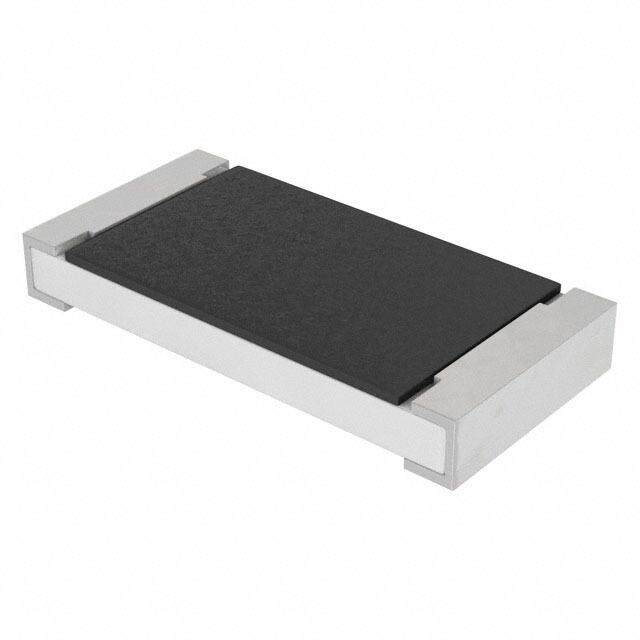
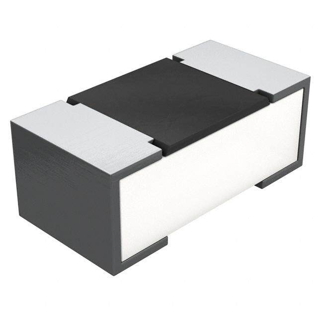
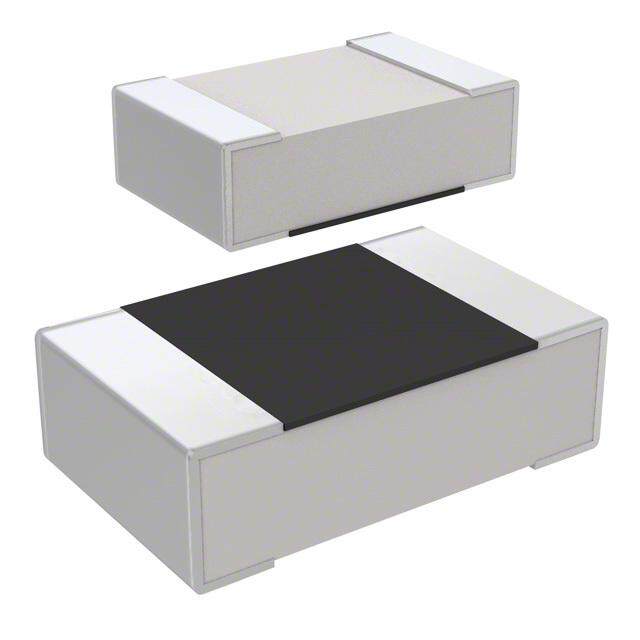
| 描述 | RES 24 OHM 2W 1% 2512 |
| 产品分类 | |
| 品牌 | TE Connectivity |
| 数据手册 | http://www.te.com/commerce/DocumentDelivery/DDEController?Action=srchrtrv&DocNm=9-1773463-5&DocType=DS&DocLang=Englishhttp://www.te.com/commerce/DocumentDelivery/DDEController?Action=srchrtrv&DocNm=2176070&DocType=Customer+Drawing&DocLang=English |
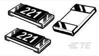
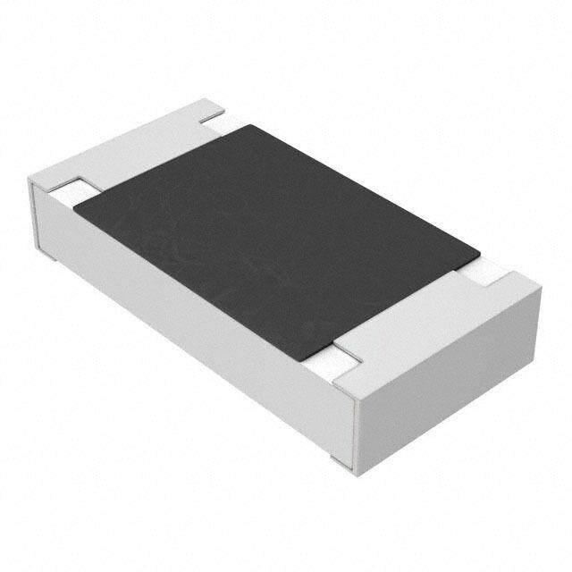
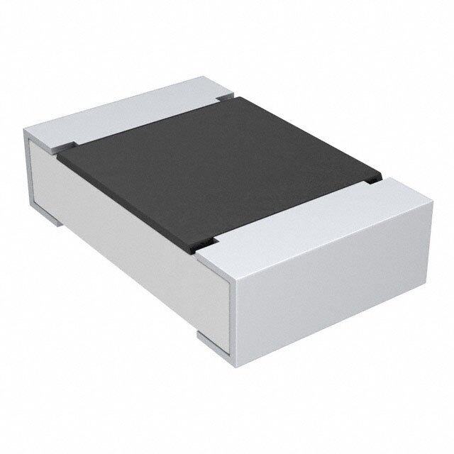
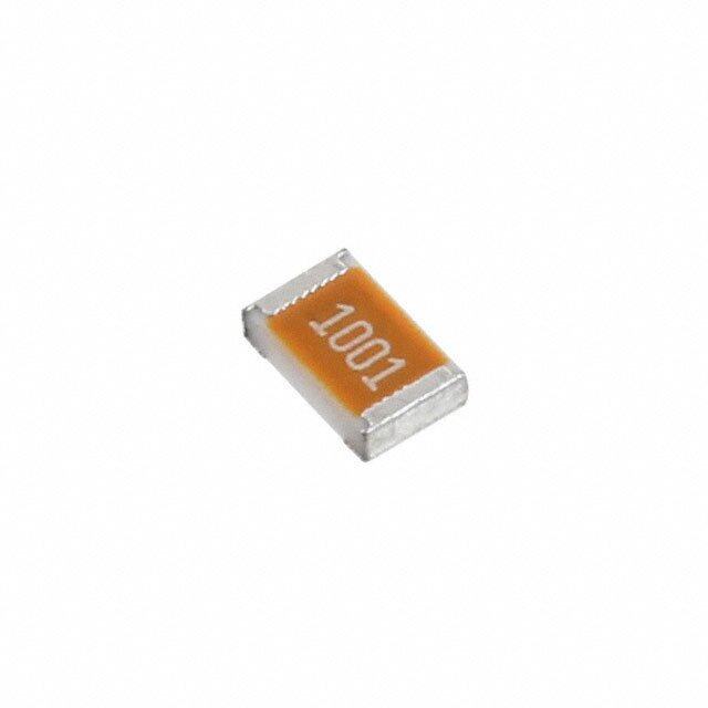
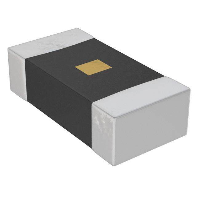
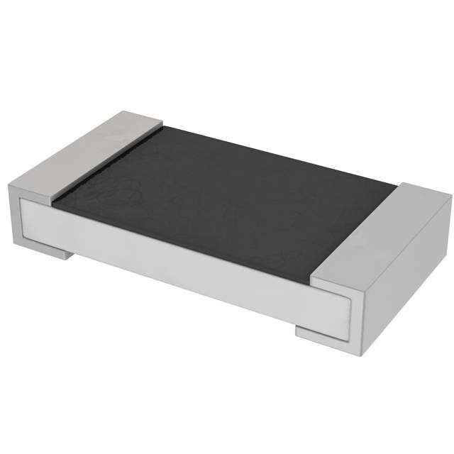
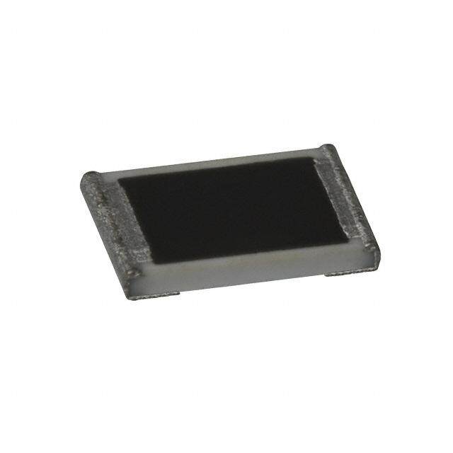
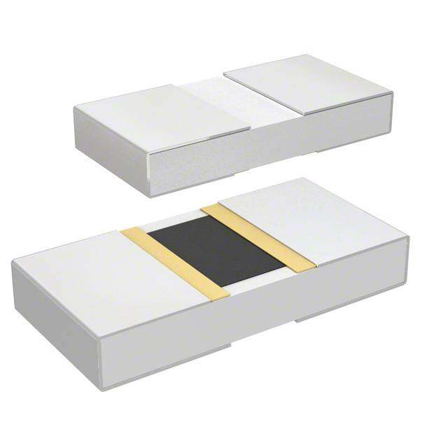
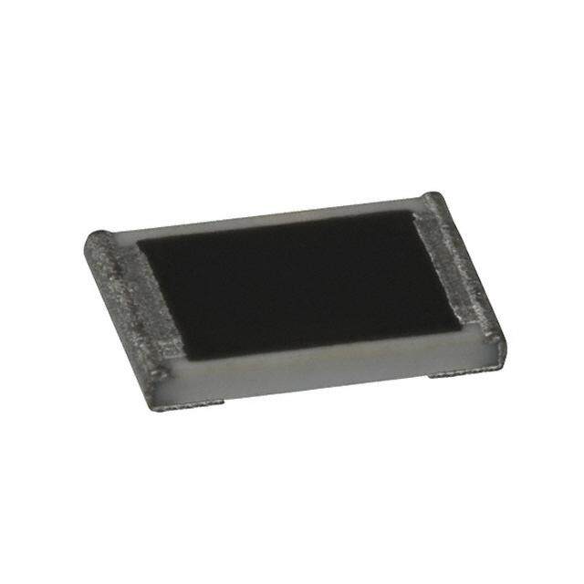
| 产品图片 |
|
| 产品型号 | 1-2176070-0 |
| rohs | 无铅 / 符合限制有害物质指令(RoHS)规范要求 |
| 产品系列 | 3521, CGS |
| 供应商器件封装 | - |
| 其它名称 | A115993DKR |
| 功率(W) | 2W |
| 包装 | Digi-Reel® |
| 大小/尺寸 | 0.248" 长 x 0.126" 宽(6.30mm x 3.20mm) |
| 容差 | ±1% |
| 封装/外壳 | 2512(6432 公制) |
| 成分 | 厚膜 |
| 标准包装 | 1 |
| 温度系数 | ±100ppm/°C |
| 特性 | - |
| 电阻(Ω) | 24 |
| 端子数 | 2 |
| 高度 | 0.026"(0.65mm) |
.jpg)


PDF Datasheet 数据手册内容提取
SMD POWER RESISTORS Type 3521 Series Key Features 2 Watts at 70°C Small size to power ratio Supplied on tape Value marked on resistor Available via distribution TE Connectivity is pleased to introduce this low cost high power device, 500 volt suitable for auto placement in volume, and for most applications, including maximum high frequency operations, owing to the short lead structure. It is overload attractively priced and available on 7" reels of 4000 pieces. 250 volt Characteristics – Electrical working voltage Power rating at 70°C 2W Max RCWV* 250V Terminal finish Max overload voltage 500V matte Sn over Resistance Tolerance 1% Ni Resistance range 1R0 - 1M0 Temperature Coefficient <10R ±200PPM 10R – 1M0 ±100PPM >1M0 ±200PPM Temperature range -55°C ~ +155°C Ambient temperature 70°C * Rated continuous working voltage (RCWV) shall be determined from RCWV = Rated Power x Resistance Value, or Maximum RCWV listed above, whichever is less **Recommended Circuit Board Design - If this device is anticipated to run at full continuous power then action to improve the cooling should be taken. This can be a metal substrate, copper pad left under the chip, an opening in the PCB or enlarged silver conductor pads each end. 9-1773463-5 CIS WR 01/2016 Dimensions in Dimensions Shown for For Email, phone or live chat, millimetres unless reference purposes only. go to: www.te.com/help otherwise specified Specifications subject to change
SMD POWER RESISTORS Power derating curve For resistors operated in ambient temperatures above 70°C, power rating must be derated in accordance with this curve. Dimensions L ± 0.10 W ± 0.15 t ± 0.10 a ± 0.25 b ± 0.20 6.35 3.20 0.55 0.60 0.50 9-1773463-5 CIS WR 01/2016 Dimensions in Dimensions Shown for For Email, phone or live chat, millimetres unless reference purposes only. go to: www.te.com/help otherwise specified Specifications subject to change
SMD POWER RESISTORS Marking: Marking for E-96 series in 2512 size: 4 digit marking First three digits are significant figures of resistance and the fourth digit represents the number of following zeros *For ohmic values below 100 Ω, letter"R" is for decimal point. Recommended PCB layout A B C 3.70 2.45 2.70 4 layers PCB specification: 1) Outside 2 layers (Top and Bottom) with copper foil thickness at 2oz. 2) Inside 2 layers (Middle layers) with copper foil thickness at 4 oz. How To Order 3521 1K0 F T Common Part Resistance Value Tolerance Pack Style 1 ohm 1R0 1K ohm 1000 ohms 3521 1K0 F – 1% T – 4000 reel 1 Meg ohm 1000000 ohms 1M0 9-1773463-5 CIS WR 01/2016 Dimensions in Dimensions Shown for For Email, phone or live chat, mil limetres unless reference purposes only. go to: www.te.com/help otherwise specified Specifications subject to change