ICGOO在线商城 > 电阻器 > 芯片电阻 - 表面安装 > 352118KFT

 Datasheet下载
- 型号: 352118KFT
- 制造商: CORCOM/TYCO ELECTRONICS
- 库位|库存: xxxx|xxxx
- 要求:
| 数量阶梯 | 香港交货 | 国内含税 |
| +xxxx | $xxxx | ¥xxxx |
查看当月历史价格
查看今年历史价格
352118KFT产品简介:
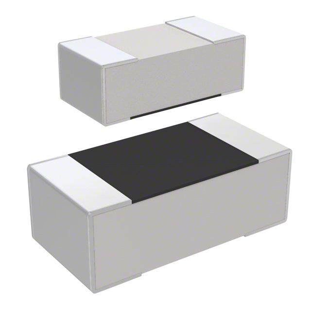
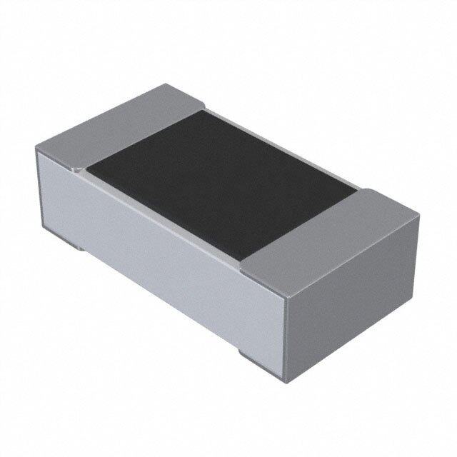
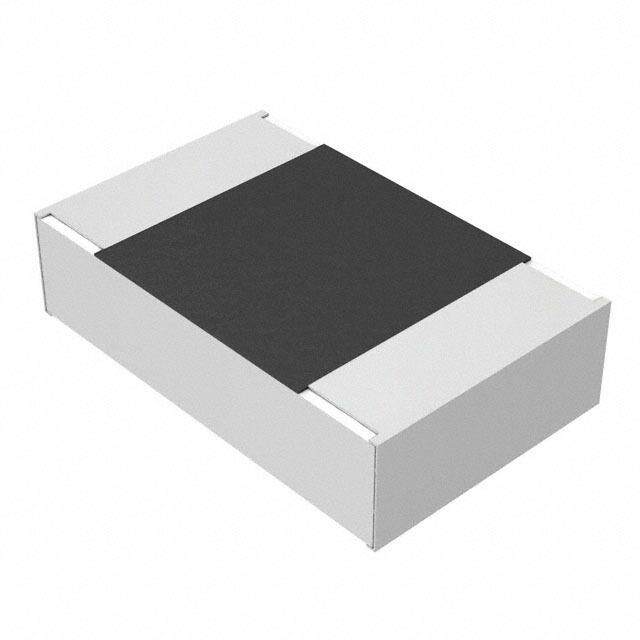
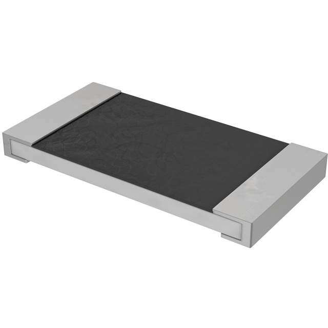
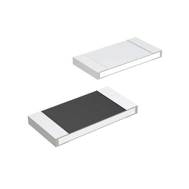
ICGOO电子元器件商城为您提供352118KFT由CORCOM/TYCO ELECTRONICS设计生产,在icgoo商城现货销售,并且可以通过原厂、代理商等渠道进行代购。 352118KFT价格参考¥0.97-¥5.24。CORCOM/TYCO ELECTRONICS352118KFT封装/规格:芯片电阻 - 表面安装, 18 kOhms ±1% 2W Chip Resistor 2512 (6432 Metric) Automotive AEC-Q200 Thick Film。您可以下载352118KFT参考资料、Datasheet数据手册功能说明书,资料中有352118KFT 详细功能的应用电路图电压和使用方法及教程。
TE Connectivity(泰科电子)旗下的352118KFT是一款芯片电阻,属于表面贴装(SMD)类型,阻值为118 kΩ,精度±1%,功率额定值通常为0.125W(1/8W),尺寸常见为0805封装。该型号电阻具有高稳定性、低温度系数和良好的耐湿性,适用于对精度和可靠性要求较高的电子电路。

352118KFT广泛应用于工业控制设备、通信模块、医疗仪器、汽车电子系统以及消费类电子产品中。在工业自动化领域,常用于传感器信号调理、电压分压电路和反馈控制回路;在通信设备中,用于偏置电路、阻抗匹配和电源管理模块;在汽车电子中,适用于ECU(电子控制单元)、车载传感器接口和电池管理系统,确保在复杂温湿度环境下稳定运行。

此外,由于其表面贴装设计,352118KFT适合自动化贴片生产,有助于提高组装效率和产品一致性。其高可靠性和紧凑尺寸也使其成为便携式医疗设备(如血糖仪、心率监测器)和智能家居控制板中的优选元件。

总之,352118KFT凭借其稳定的电气性能和广泛的工作环境适应能力,适用于多种对精度和长期可靠性有要求的中高端电子应用场景。
| 参数 | 数值 |
| 产品目录 | |
| 描述 | RES 18K OHM 2W 1% 2512 |
| 产品分类 | |
| 品牌 | TE Connectivity |
| 数据手册 | http://passives.te.com/documents/webservice/fetch.ashx?fileid=15905&docId=10864 |
| 产品图片 |
|
| 产品型号 | 7-2176070-9 |
| rohs | 无铅 / 符合限制有害物质指令(RoHS)规范要求 |
| 产品系列 | 3521, CGS |
| 供应商器件封装 | - |
| 其它名称 | 352118KFT |
| 功率(W) | 2W |
| 包装 | 带卷 (TR) |
| 大小/尺寸 | 0.248" 长x 0.126" 宽(6.30mm x 3.20mm) |
| 容差 | ±1% |
| 封装/外壳 | 2512(6432 公制) |
| 成分 | 厚膜 |
| 标准包装 | 4,000 |
| 温度系数 | ±100ppm/°C |
| 特性 | - |
| 电阻(Ω) | 18k |
| 端子数 | 2 |
| 高度 | 0.026"(0.65mm) |
.jpg)


- 商务部:美国ITC正式对集成电路等产品启动337调查
- 曝三星4nm工艺存在良率问题 高通将骁龙8 Gen1或转产台积电
- 太阳诱电将投资9.5亿元在常州建新厂生产MLCC 预计2023年完工
- 英特尔发布欧洲新工厂建设计划 深化IDM 2.0 战略
- 台积电先进制程称霸业界 有大客户加持明年业绩稳了
- 达到5530亿美元!SIA预计今年全球半导体销售额将创下新高
- 英特尔拟将自动驾驶子公司Mobileye上市 估值或超500亿美元
- 三星加码芯片和SET,合并消费电子和移动部门,撤换高东真等 CEO
- 三星电子宣布重大人事变动 还合并消费电子和移动部门
- 海关总署:前11个月进口集成电路产品价值2.52万亿元 增长14.8%


PDF Datasheet 数据手册内容提取
SMD POWER RESISTORS AEC-Q200 QUALIFIED Type 3521 Series Key Features 2 Watts at 70°C Small size to power ratio Supplied on tape Value marked on resistor 500 volt maximum overload 250 volt maximum TE Connectivity is pleased to announce that our 3521 series high power Thick Film working Chip Resistor is now AEC-Q200 Qualified. This low cost device, suitable for auto voltage placement in volume, and for most applications, including high frequency operations, owing to the short lead structure, is attractively priced and available on Terminal finish 7" reels of 4000 pieces. matte Sn over Ni Characteristics – Electrical AEC-Q200 Power Rating 2W Qualified Resistance Range 0.1Ω ~ 10MΩ Tolerance ±1% ±5% Max. Working Voltage 250V Max. Overload Voltage 500V Dielectric Withstanding Voltage 500V Temperature Range -55°C ~ +155°C Ambient Temperature 70°C Resistors shall have a power rating based on continuous load operation at an ambient temperature of 70 . For temperature in excess of 70 , The load shall be derated as shown below: ℃ ℃ 9-1773463-5 Rev G 02/2020 Dimensions in Dimensions Shown for For Email, phone or live chat, millimetres unless reference purposes only. go to: www.te.com/help otherwise specified Specifications subject to change
SMD POWER RESISTORS AEC-Q200 QUALIFIED Voltage Rating: Resistors shall have a rated direct-current (DC) continuous working voltage or an approximate sine-wave root-mean-square (RMS) alternating-current (AC) continuous working voltage at commercial line frequency and waveform corresponding to the power rating , as determined from the following formula: RCWV = √P x R Where: RCWV = Rated DC or RMS AC continuous working voltage at commercial-line frequency and waveform (volt) P = Power Rating (watt) R = Nominal Resistance (ohm) In no case shall the rated DC or RMS AC continuous working voltage be greater than the applicable maximum value. Construction & Dimensions: Dimensions: (mm) L W H ℓ(cid:1005) ℓ(cid:1006) 6.35±0.10 3.20±0.20 0.55±0.10 0.60±0.25 0.50±0.20 9-1773463-5 Rev G 02/2020 Dimensions in Dimensions Shown for For Email, phone or live chat, millimetres unless reference purposes only. go to: www.te.com/help otherwise specified Specifications subject to change
SMD POWER RESISTORS AEC-Q200 QUALIFIED Recommended solder pad A C B Width Spacing Pad (mm) (mm) (mm 3.0 1.5 5.0 4 layers PCB specification: 1) Outside 2 layers (Top and Bottom) with copper foil thickness at 2oz. 2) Inside 2 layers (Middle layers) with copper foil thickness at 4 oz. Marking: For E24 series Values three digit marking, the first two digits are significant figures and the third denoting number of zeros. E.G. 333 (cid:1007)(cid:1007)KΩ For Oh(cid:373)i(cid:272) Values (cid:271)elo(cid:449) (cid:1005)(cid:1004)Ω E.G. 3R3 (cid:1007).(cid:1007)Ω For E96 Values four digit marking, the first three showing significant figures and the fourth showing number of zeros. As previously letter R is for decimal point. E.G. 4992 49K9Ω 9-1773463-5 Rev G 02/2020 Dimensions in Dimensions Shown for For Email, phone or live chat, millimetres unless reference purposes only. go to: www.te.com/help otherwise specified Specifications subject to change
SMD POWER RESISTORS AEC-Q200 QUALIFIED Performance Specification: Characteristics Limits Test Methods 125°C, at 35% of operating power, 1000H ±(cid:894)(cid:1005)%+(cid:1004).(cid:1005)Ω(cid:895)(cid:373)a(cid:454) (cid:894)(cid:1005).(cid:1009) hours (cid:862)ON(cid:863), (cid:1004).(cid:1009) hour (cid:862)OFF(cid:863)(cid:895). Operational life (MIL-STD-202) <(cid:1005)(cid:1004)(cid:1004)(cid:373)Ω Apply to rate current for 0Ω Parametrically test per lot and sample size (cid:1004).(cid:1005)Ω<R≤(cid:1004).(cid:1013)(cid:1011)(cid:1010)Ω ±100PPM requirements, summary to show Min, Max, Electrical (cid:1005)Ω R ≤(cid:1005)(cid:1004)Ω ≤ ±(cid:1008)(cid:1004)(cid:1004)PPM/°C Mean and Standard deviation at room as Characterisation (cid:1005)(cid:1004)Ω < R (cid:1005)(cid:1004)(cid:1004)Ω ≤ ±200PPM/°C well as Min and Max operating (cid:1005)(cid:1004)(cid:1004)≦Ω<R 10MΩ ≤ ±100PPM/°C temperatures. (User Spec) ≦ Electrical test not required. Inspect device ≦ External Visual No Mechanical Damage construction, marking and workmanship (MIL-STD-883 Method 2009) Verify physical dimensions to the applicable device detail specification. Physical Reference 2.0 Dimension Note: User(s) and Suppliers spec. Electrical Dimension Standards test not required. (JESD22 MH Method JB-100) Note: Add Aqueous wash chemical – OKEM Resistance to Clean or equivalent. Marking Unsmeared Solvent Do not use banned solvents. ( MIL-STD-202 Method 215) Force of 1.8kg for 60 seconds. Terminal Strength Not broken (JIS-C-6429) 1000hrs. @T=155°C.Unpowered. High Temperature Resistance change rate is Measurement at 24±2 hours after test Exposure ± (cid:894)(cid:1004).(cid:1009)%+(cid:1004).(cid:1005)Ω(cid:895) Ma(cid:454). conclusion. (Storage) (MIL-STD-202 Method 108) <(cid:1009)(cid:1004)(cid:373)Ω Appl(cid:455) to rate (cid:272)urre(cid:374)t for (cid:1004)Ω 1000 Cycles (-55°C to +155°C). Measurement Resistance change rate is Temperature at 24±2 hours after test conclusion ± (cid:894)(cid:1004).(cid:1009)%+(cid:1004).(cid:1005)Ω(cid:895) Ma(cid:454). cycling (JESD22 Method JA-104) <(cid:1009)(cid:1004)(cid:373)Ω Appl(cid:455) to rate (cid:272)urre(cid:374)t for (cid:1004)Ω Resistance change rate is Moisture ± (cid:894)(cid:1004).(cid:1009)%+(cid:1004).(cid:1005)Ω(cid:895) Ma(cid:454). Resistance T=24 hours /cycle. Unpowered. Measurement at 24±2 hours after test conclusion. (MIL-STD-202 Method 106) <(cid:1009)(cid:1004)(cid:373)Ω Appl(cid:455) to rate (cid:272)urre(cid:374)t for (cid:1004)Ω 10% rated power, 85°C/85%RH, 1000H. Resistance change rate is Measurement at 24 hours after test Biased Humidity ± (cid:894)(cid:1005)%+(cid:1004).(cid:1005)Ω(cid:895) Ma(cid:454) conclusion. (MIL-STD-202 Method 103) <(cid:1005)(cid:1004)(cid:1004)(cid:373)Ω Appl(cid:455) to rate (cid:272)urre(cid:374)t for (cid:1004)Ω Wave Form: Tolerance for half sine shock pulse. Peak (cid:448)alue is (cid:1005)(cid:1004)(cid:1004)g’s. Nor(cid:373)al duratio(cid:374) Mechanical Shock ±(1%+0.1Ω) max (D) is 6. (MIL-STD-202 Method 213) (cid:1009)g’s for (cid:1006)(cid:1004) (cid:373)i(cid:374)., (cid:1005)(cid:1006)(cid:272)(cid:455)(cid:272)le ea(cid:272)h of (cid:1007) orientations. Note: Use (cid:1012)(cid:863)*(cid:1009)(cid:863)PCB. (cid:1004)(cid:1007)(cid:1005)(cid:863) thi(cid:272)k (cid:1011) se(cid:272)ure points (onone) long side and 2 secure points Vibration ±(1%+0.1Ω) max at corners of opposite sides. Parts mounted (cid:449)ithi(cid:374) (cid:1006)’ fro(cid:373) a(cid:374)(cid:455) se(cid:272)ure poi(cid:374)t. Test from 10-2000Hz. (MIL-STD-202 Method 204) 9-1773463-5 Rev G 02/2020 Dimensions in Dimensions Shown for For Email, phone or live chat, millimetres unless reference purposes only. go to: www.te.com/help otherwise specified Specifications subject to change
SMD POWER RESISTORS AEC-Q200 QUALIFIED Performance Specification (continued) Characteristics Limits Test Methods -55°C/+155°C Note: Number of cycles required -300, ±(1%+0.1Ω(cid:895) max Maximum transfer time -20 seconds, Dwell Thermal Shock time -15 minutes. Air-Air. (MIL-STD-202 Method 107) <50mΩ Apply to rate current for 0Ω With the electrometer in direct contact with the discharge tip, verify the voltage setting at levels of ESD ±(10%+0.1W)max ±500V,±1KV, ±2KV, ±4KV, ±8KV, The electrometer reading shall be within ±10% for voltages from 500V to 800V. (AEC-Q200-002) For both leaded & SMD. Electrica≦l test not required Magnification 50X. Conditions: a) Method B 4hrs at 155°C dry heat, the dip Solderability 95% coverage Min. in bath with 245°C,5s. b) Method B: at 215°C,5s. c) Method D: at 260°C, 60s. ( J-STD-002) V-0 or V-1 are acceptable. Electrical test not No ignition of the tissue paper or Flammability required. scorching of the pinewood board (UL-94) ±(1%+0.05W)max 2mm (Min) (JIS-C-6429) Board Flex <50mW Apply to rate current for 0 W Temperature sensing at 500, Voltage power subjected to 32VDC current clamped Flame Retardance No flame up to 500ADC and decreased in 1.0VDC/hour. ( AEC-Q200-001) Condition B No per-heat of samples. Note: Single Wave Solder-Procedure 2 for SMD Resistance to ±(cid:894)(cid:1005)%+(cid:1004).(cid:1004)(cid:1009)Ω(cid:895)(cid:373)a(cid:454). and Procedure 1 for Leaded with solder soldering Heat within 1.5mm of device body. (MIL-STD-202 Method 210) <50mW Apply to rate current for 0 W * Sulfuration test: H2S 3~5PPM 50°C±2°C 91%~93%RH 1000H Packaging specification Embossed Taping: A B C ØD+0.1 ØD1+0.1 E F G W T ± ±0.2 ±0.2 ±0.05 -0 -0 ±0.1 ±0.05 ±0.1 ±0.2 0.1 3.50 6.70 2.0 1.5 1.5 1.75 5.5 4.0 12.0 1.0 9-1773463-5 Rev G 02/2020 Dimensions in Dimensions Shown for For Email, phone or live chat, millimetres unless reference purposes only. go to: www.te.com/help otherwise specified Specifications subject to change
SMD POWER RESISTORS AEC-Q200 QUALIFIED Peeling Strength of Top Cover Tape Test Condition: 0.1 to 0.7 N at a peel-off speed of 300 mm / min. Reel Dimensions Tape Reel A ± B ± C ± D ± 1 M ± 2 W ± 1 Qty 0.5 0.5 0.5 Embossed 4,000 2 13 21 60 178 13.8 Environment Related Substance This product complies to EU RoHS directive, EU PAHs directive, EU PFOS directive and Halogen free. Ozone layer depleting substances. Ozone depleting substances are not used in our manufacturing process of this product. This product is not manufactured using Chloro fluorocarbons (CFCs), Hydrochlorofluorocarbons (HCFCs), Hydrobromofluorocarbons (HBFCs) or other ozone depleting substances in any phase of the manufacturing process. 9-1773463-5 Rev G 02/2020 Dimensions in Dimensions Shown for For Email, phone or live chat, millimetres unless reference purposes only. go to: www.te.com/help otherwise specified Specifications subject to change
SMD POWER RESISTORS AEC-Q200 QUALIFIED Storage Condition The performance of these products, including the solderability, is guaranteed for a year from the date of arrival at your company, provided that they remain packed as they were when delivered and stored at a temperature of 25°C ± 10°C and a relative humidity of 60%RH ± 10%RH, chemical and dust free atmosphere Even within the above guarantee periods, do not store these products in the following conditions, otherwise their electrical performance and/or solderability may be deteriorated, and the packaging materials (e.g. taping materials) may be deformed or deteriorated, resulting in mounting failures. 1. In salty air or in air with a high concentration of corrosive gas, such as Cl2, H2S, NH3, SO2, or NO2 2. In direct sunlight AEC-Q200 The 3521 series is qualified to AEC-Q200 standard at Grade"4" How To Order 3521 10K F T Common Part Resistance Value Tolerance Pack Style 1Ω - 1R0 100Ω - 100R 3521 – SMD 1,000Ω (1KΩ) -1K0 F – 1% T – 4000 Reel Power Resistor 10,000Ω (10KΩ) - 10K 1,000,000Ω (1MΩ) - 1M0 9-1773463-5 Rev G 02/2020 Dimensions in Dimensions Shown for For Email, phone or live chat, millimetres unless reference purposes only. go to: www.te.com/help otherwise specified Specifications subject to change