
 Datasheet下载
- 型号: 3314Z-1-203E
- 制造商: Bourns
- 库位|库存: xxxx|xxxx
- 要求:
| 数量阶梯 | 香港交货 | 国内含税 |
| +xxxx | $xxxx | ¥xxxx |
查看当月历史价格
查看今年历史价格
3314Z-1-203E产品简介:
ICGOO电子元器件商城为您提供3314Z-1-203E由Bourns设计生产,在icgoo商城现货销售,并且可以通过原厂、代理商等渠道进行代购。 3314Z-1-203E价格参考。Bourns3314Z-1-203E封装/规格:微调电位计, 20 kOhms 0.25W,1/4W J 引线 表面贴装 微调电位器 金属陶瓷 1 匝 侧面调节。您可以下载3314Z-1-203E参考资料、Datasheet数据手册功能说明书,资料中有3314Z-1-203E 详细功能的应用电路图电压和使用方法及教程。
Bourns Inc.生产的型号为3314Z-1-203E的微调电位计是一种精密可调电阻元件,广泛应用于需要精确调节电压、电流或信号电平的场景。以下是其主要应用场景:

 1. 音频设备
   - 用于调节音量、音调或平衡控制。
   - 应用于音响系统、耳机放大器、混音台等设备中,实现音频信号的精细调整。

 2. 工业控制
   - 在自动化控制系统中,用作校准元件,调节传感器输出或控制器参数。
   - 应用于变频器、伺服驱动器和PLC(可编程逻辑控制器)中,以优化性能。

 3. 医疗设备
   - 用于医疗仪器中的信号调节,例如心率监测仪、血压计或超声波设备。
   - 提供高精度的电阻调节,确保测量结果的准确性。

 4. 通信设备
   - 用于调节射频信号的增益或衰减。
   - 应用于无线通信模块、路由器或调制解调器中,优化信号质量。

 5. 消费电子产品
   - 在家用电器中用于调节亮度、对比度或其他参数。
   - 应用于电视、显示器或投影仪的电路板中,实现图像或声音的优化。

 6. 测试与测量仪器
   - 用于校准万用表、示波器、信号发生器等设备。
   - 提供稳定的电阻值调整,确保测量结果的可靠性。

 7. 汽车电子
   - 用于调节车内电子系统的参数,如灯光亮度、温度控制或音响系统。
   - 应用于电动车窗、后视镜调节或导航系统中。

 特性优势
- 小型化设计:适合空间受限的应用环境。
- 高稳定性:在多种温度和湿度条件下保持性能稳定。
- 长寿命:支持频繁调节,满足长期使用需求。

总之,3314Z-1-203E微调电位计凭借其高精度和可靠性,成为众多电子设备中不可或缺的元件,适用于需要精密电阻调节的各类场景。
| 参数 | 数值 |
| 产品目录 | |
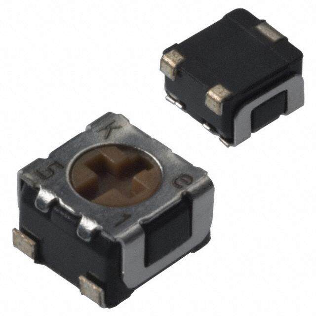
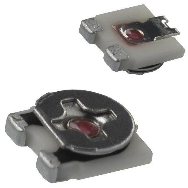
| 描述 | TRIMMER 20K OHM 0.25W SMD微调电阻器 - 表面贴装 4mm SQ 20K |
| 产品分类 | |
| 品牌 | Bourns Inc. |
| 产品手册 | |
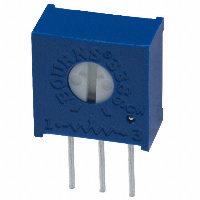
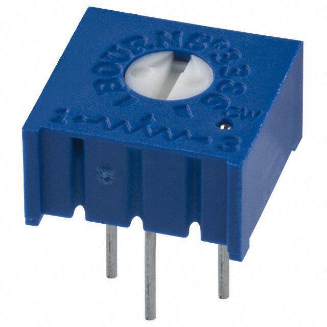
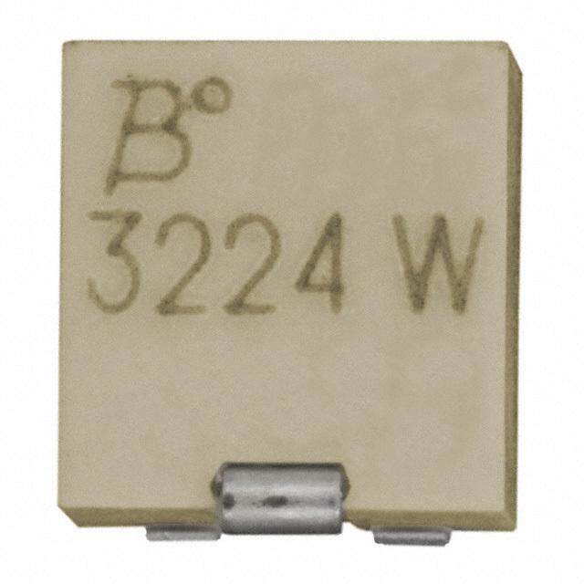
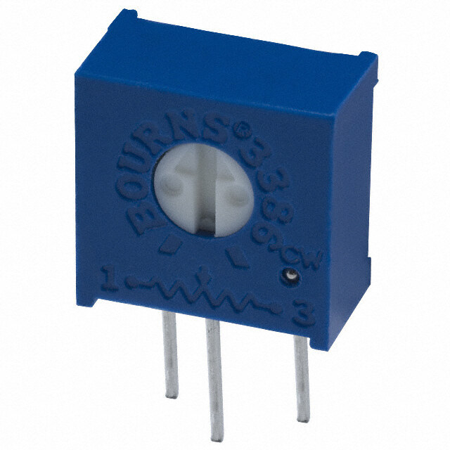
| 产品图片 |
|
| rohs | RoHS 合规性豁免无铅 / 符合限制有害物质指令(RoHS)规范要求 |
| 产品系列 | 微调电阻器 - 表面贴装,Bourns 3314Z-1-203ETrimpot® 3314 - 密封式 |
| 数据手册 | |
| 产品型号 | 3314Z-1-203E |
| 产品 | Trimmers |
| 产品目录绘图 |
|
| 产品目录页面 | |
| 产品种类 | 微调电阻器 - 表面贴装 |
| 产品类型 | Single Turn |
| 元件类型 | Cermet |
| 其它名称 | 3314Z-203EDKR |
| 功率(W) | 0.25W,1/4W |
| 功率额定值 | 250 mW (1/4 W) |
| 包装 | Digi-Reel® |
| 商标 | Bourns |
| 商标名 | Trimpot |
| 圈数 | 单路 |
| 大小/尺寸 | 方形 - 0.219" x 0.197" 表面 x 0.227" 高 (5.56mm x 5.01mm x 5.76mm) |
| 安装类型 | 表面贴装 |
| 容差 | ±20% |
| 封装 | Reel |
| 尺寸 | 4.5 mm W x 4.50 mm L x 2.55 mm H |
| 工作温度范围 | - 55 C to + 125 C |
| 工厂包装数量 | 200 |
| 标准包装 | 1 |
| 温度系数 | ±100ppm/°C |
| 电阻 | 20 kOhms |
| 电阻(Ω) | 20k |
| 电阻材料 | 金属陶瓷 |
| 端子类型 | J 引线 |
| 端接类型 | SMD/SMT |
| 类型 | Trimming Potentiometer |
| 系列 | 3314 |
| 调整 | Top Slot |
| 调节类型 | 侧面调节 |
| 转数 | 1 |
| 锥度 | Linear |


- 商务部:美国ITC正式对集成电路等产品启动337调查
- 曝三星4nm工艺存在良率问题 高通将骁龙8 Gen1或转产台积电
- 太阳诱电将投资9.5亿元在常州建新厂生产MLCC 预计2023年完工
- 英特尔发布欧洲新工厂建设计划 深化IDM 2.0 战略
- 台积电先进制程称霸业界 有大客户加持明年业绩稳了
- 达到5530亿美元!SIA预计今年全球半导体销售额将创下新高
- 英特尔拟将自动驾驶子公司Mobileye上市 估值或超500亿美元
- 三星加码芯片和SET,合并消费电子和移动部门,撤换高东真等 CEO
- 三星电子宣布重大人事变动 还合并消费电子和移动部门
- 海关总署:前11个月进口集成电路产品价值2.52万亿元 增长14.8%
PDF Datasheet 数据手册内容提取
5.00 2.55 (.197) (.100) TAPE TAPE 6.20 2 (.244) (0.0.5210 ±± 0.0.1035) (.0.3102) MAX. 0.25 ± 0.10 TYP. (.010 ± .004) 2.74 ± 0.10 (.108 ± .004) 3.5 ± 0.10 4.50 0.51 ± 0.13 5.50 ± 0.5 (.138 ± .004) 6 ° ± 2 ° (.177) (.020 ± .005) (.217 ± .020) 5.52 ± 0.05 TYP. DIA. (.217 ± .002) 1.50 + 0.10/ - 0.00 5.26 ± 0.10 (J) R 0.13 (.059 + .004/ - .000) (.207 ± .004) 1.50 + 0.10/ - 0.00 (.005) 6.45 ± 0.10 (G) (.059 + .004 - .00) 6.48 ± 0.10 3 1 TYP.(0.0.2008) MTYAPX.. (4.1.0507 ±± 0.0.1004) (.254 ± .004) D4.I0A0. ± 0.10 (.255 ± .004) (.157 ± .004) Features n Side adjust available 5.26 ± 0.10 n Surface Mount / Single Turn / Cermet n Meets EIA/EIAJ/IPC/VECI RLSAEYCMOOUMDTM sEtNaDnEDd PaCrBd (2.0.0709 ±± 0.0.0250) (.207 ± .004) 2.00 ± 0.05 (5.2.2067 ±± 0.0.1004) Industrial / Sealed t2r.i3m5 mer designs (.20.930) (.079 ± .002) n Compatible with surface mount n (R.0o92H)S complian(0.t0.*8301 - ±± s0.0e.10e04) processing (.10.531) (1.0.5509 ++ 0.0.1004/ -- .00.0000) manufacturing processes information on le2a PdL CfSr.ee surface mo2u PnLtC S. 8.00 ± 0.20 DIA. n Compatible with popular vacuum trimmers DIA. (.315 ± .008) 3.2 DIA. pick-and-place equipment n6. 2F0or trimmer applica(.1t2io6)ns/processin5g.5 (1.0.7659 ±± 0.0.1004) 1.50 + 0.10/ - 0.00 1.75 ± 0.10 n J-hook, gull-wing & pinned configurations (.24g4)uidelines, click heTrHeRU. (.216) 12.00 ± 0.30 (.059 + .004/ - .000) (.068 ± .004) 12.00 ± 0.30 n AEC-Q200 Qualified Grade 1 (.472 ± .012) (4.72 ± .012) 3314 - 4 mm Square Trimpot® Trimming Potentiometer 2.0 REEL REEL 1.30 ± 0.10 (.079) 5.00 (.051 ± .004) (.10.531) MIN.(1.0.5509) EQUAL SPACED 3 PLCS. MIN.(1.0.5509) EQUAL SPACED 3 PLCS. (.197) 2 PLCS. 20.2 20.2 (.795) 18.4 (.795) 18.4 Electrical Characteristics Product Dimensions 13.0 ± 0.51 MIN. DIA. (.724) 13.0 ± 0.51 MIN. DIA. (.724) Standard Resistance Range 3314J-1 3314J-1, G-1, R-1, H-1 3314J-2, G-2, R-2, H-2 (.512D ±IA ..020) (MEMASAUXR.ED (.512D ±IA ..020) (MEMASAUXR.ED R e .s..is..t.a..n..c..(e.s. .eT.e.o.( .tls.ei.gtr1aha0ntn edocraeh tr mod..l. se.r. er. a.ts.oni.s. c.2te±a m n2ac0vee ag% iotlaa hsbbmtlldees.)) (4.1.25707) (2.1.5050) (SBtorauirg2nhsCt O (MS4.M1l.2Aa57MoL07rtOL)k)S NPTi nIRDNgAI MSI,G TEHYNTLSEIOSN:S -(C Broous POrsI2n (NU 5.S1SsT.09CS l A0o7MOI DR t±M±EEa)A 0M. rL0WP.k1LO0ACH0 4iNRPRnE) IA ODNNgLSI ,MLS SETE L YN L SEISO:NS - (51H0.9AU.06TB09)) (51H0.9AU.06TB09)) ADJ. SLOT ADJ. SLOT End Resistance .....1 % or 2 ohms max. 0.20 2.45 LONG6.30 2.41 LONG MIN. MIN. Co ntact Resistance(w Vhairciahteiovenr is greater) (4.1.5707) (.0T0Y8P). X( ( ...00592160))W(4.1I.D57E07().248) X( ( ...00592150))W(.0I0TD.0Y2E8P0). ....................................3 % or 3 ohms 3 1 X ( ..05210) DEEP 3 1 X ( ..05210) DEEP Resolution ...................................Infinite 177.8 ± 2.03 177.8 ± 2.03 DIA.* DIA.* Insulation Resistance ...............500 vdc. 3 1 RECOMMENDED PCB 3314J-3, G-3, R-3, H-3 3314J-4, G-4, R-4, H-4 (7.00 ± .080) 12.4 + 2.01/ -.000 (7.00 ± .080) 12.4 + 2.01/ -.000 D ieS leeac tLriecv Selt.r.e..n..g..t.h......150000 m veagco (1h mmsin mutine.) (2.0.3953) (.003.81 ±± 0.0.104)LAYOUT (.20.931)1.3 (SRtreaviegrhsCt3e OS MMlAoMLatLO)r1 NkP IiDNnI gMST,E YNLSEISO:NS (C-Rr(eo2.1.vs50e50s)r sSCeloO MMt)AMaLLOr kNPi I(nDN4.1I g.MS05,T07E Y)NLTSEYISOP:N.S - (1333.00.02 ±± .20.709)DIA.** (M(.4E8A8S +U R.0E7D9 /A -T . 0H0U0B)) (1333.00.02 ±± .20.709)DIA.** (M(.4E8A8S +U R.0E7D9 /A -T . 0H0U0B)) Adjustment Angle .................210 ° nom. 2 PLCS. (.051) 2 STRAIGHT 2 CROSS * Embossed Tape Designator "E" * Embossed Tape Designator "E" 2 PLCS. ADJ. SLOT ADJ. SLOT ** Embossed Tape Designator "G" ** Embossed Tape Designator "G" Environmental Characteristics (2.0.495(62.)1.L50O50N)G (2.0.49152).5L5ONG (See How To Order chart for further information.) (See How To Order chart for further information.) PJ o&w He;r 5 R0a vtoinltgs (m30a0x .v foolrt sS mtyalex .R f)o r Style G, (5.1.0907) 3( .P10L.40C0S). (4.1.0507) 3 1 XX ( ( ....0055221100)) (WD.0E0I32DE. 64EPP L±±C 0.0S.10.4)3 1 XX ( ( ....00552211(00.1)) 0WD0EI)DEEP Meets EIA specification 481. Meets EIA specification 481. 70 °C ....................................0.25 watt TTee1mm2pp5ee °rrCaatt uu..rr..ee.. .RC..ao..ne..gffi..e.c. ..i..e...n-.5.t. 5.... ..°.±.C.1. .0t..o0.. .+p..1p02m 5w/ a°°CCtt (5.1.0907) (.10.5310 ±± .00.014) (.20.709) (.20.709) (5.1.0907) (.00.3810) Seal Test ..85 °C Fluorinert†/60 seconds 3 PLCS. DIA. TYP. Humidity ............................90-98 % RH, 5.00 10 cycles, 240 hours 3314G-1 (.197) 4.50 TRS ±2 %; IR 10 megohms (.177) 2.55 Vibration .....20 G TRS ±1 %; VRS ±1 % 2 (.100) 0.20 Shock .......100 G TRS ±1 %; VRS ±1 % (.008) TYP. Load Life 4.50 ....(@ 70 °C Rated Power 1000 Hours) (.177) 2.55 COMMON DIMENSIONS - COMMON DIMENSIONS - Ro tational Life .......................1T0R0S c ±y3c le%s 2 (4.1.5707) (.100) (.00.264)TYP. 2 ALLSA PTDIRJN.A SSIGLTHOYTLTES: 2 ALLAC PDRIJON.S SSSLT O Y LT ES: TRS ±3 % (.00.0280) (2.0.4956)LONG (2.0.4915)LONG T h ermal Shock ....T...R..S.. .±..2.. .%....;. .V..R5 S c ±y1c le%s 3 1 (4.1.5707) RE5C°TO MYMPAM.XE.NDED PCB TYP. 3 1 XX ( ( ....0055221100)) WDEIDEEP 3 1 XX ( ( ....0055221100)) WDEIDEEP Physical Characteristics 2.35 LAYOUT Mechanical Angle .................240 ° nom. 3 1 (.093) RECOMMEND2E.D3 PCB Torque .............................180 g-cm max. 2.35 0.8 ± 0.1 LAYOUT (.091)1.3 Stop Strength ..................300 g-cm min. (.093) ((..000233. 181P ±L±±C .0.0S0.0.1044)) (.220( ..9P031L5)C11)S.3. COMAMLLO NP IDNI MSTEYNLSEISO:NS - COMAMLLO NP IDNI MSTEYNLSEISO:NS - Pushover Strength (S & Z Style) 2 PLCS. (.051) 2 STRAIGHT 2 CROSS ................1.6 kilograms (3.5 lbs.) min. 2 PLCS. ADJ. SLOT ADJ. SLOT Weight ...............Approximately 0.01 oz. 6.20 5.5 (2.0.4956)LONG (2.0.4915)LONG M Wai prkeirn .g.. ....r..e....s....i..s....t..a...n5..c0..e M% cao (nAduecf taaucnatdlu T rdeRar)’ts e± c 1co0od d%ee, ((.5.21.409407)) 33(( ..PP1010LL.5.430CC10SS)).. (.2(14.17.05)07) 3 1 XX ( ( ....0055221100)) WDEIDEEP 3 1 XX ( ( ....0055221100)) WDEIDEEP Flammability ..........................U.L. 94V-0 11..3300 ±± 00..11 (.20.709) S tJa,n Gda ardn dP Rac .k..a5g0i0n gpcs./7 ” reel (MSL-1) ((5.5.11..09090707)) ((..005511 ±± ..000044)) (.20.709) (.20.709) DIMENSIONS: MM S and Z ........200 pcs./7 ” reel (MSL-1) 3 PLCS. (INCHES) H ....................................100 pcs./tube TOLERANCES: ± 0.30 EXCEPT WHERE NOTED Adjustment Tool ..............................H-90 (.012) 4.50 (.177) 2.55 2 (.100) 0.20 (.008) WARNING Cancer and Reproductive Harm - www.P65Warnings.ca.gov TYP. *RoHS Directive 2015/863, Mar. 31, 2015 and Annex “Trimpot” is a trademark of Bourns, Inc. †“Fluorinert” is a registered trademark of 3M Co4..50 0.6 Specifications are subject to change without notice. Users should verify actual device perfo(.r1m77a)nce in their specific apTYpPli.cations. (.024) The products described herein and this document are subject to specific legal disclaimers as set forth on the last page of this document, and at www.bourns.com/docs/legal/disclaimer.pdf. 5° MAX. TYP. 3 1 RECOMMENDED PCB 2.35 LAYOUT (.093) 2.3 (.091) 0.8 ± 0.1 1.3 (.031 ± .004) (.051) 2 PLCS. 2 PLCS. 6.20 5.5 (.244) 1.3 (.217) (.051) 3 PLCS. 2.0 1.30 ± 0.1 (.079) (.051 ± .004) 5.00 (.197)
3314 - 4 mm Square Trimpot® Trimming Potentiometer Product Dimensions 5.00 2.55 (.197) (.100) TAPE TAPE TAPE 2 (6.2.2404) (0.0.5210T Y±±P 0..0.1035) (.0.3102) MAX. (20..5140) (01.0.4526 ±± 00..10305) (0.0.21505 .±±6 10.0.1004) (0.0.5200 ±± 0.0.0052) 2.74 ± 0.10 (0.221) (.108 ± .004) 1.273.5 ± 0.10 4.50 0.51 ± 0.13 5.50 ± 0.5 (0.0(5.)138 ± .004) 1.05 6 ° ± 2 ° 4.5 (.177) (.020 ± .005) (.217 ± .020) (0.041) 5.52 ±(0 0.1.0757) TYP. DIA. 1 2 3 (.217 ± .002) 3 1 TYP.(0.0.2008) R ( .0MT0.Y01AP53X.) . (1.0.55(094.1 .++05 070.0 .±±10 040.0//. 10--04 0.RWO)0.OF00I 00TTT)HOEIRRNM P±IO N2SA2IL T° I 2OO N F ECDE NATSE SRHLOINWE((N5.6.22..20456754 ±±±± 0.0.00..10100404 )) ((GJ)) 1(..05509 + + 0D4 ...0I10A000.4/ ± -- 00.0..10000) (6.2.4585 ±± 0.0.1004) 1(7..27.59505 ± ±± 0 0..01.10004) (.1663.00 0± ±0 .00.132) (.157 ± .004) (.069 ± .004) R 0 . 5 TYP. RECOMMENDED PCB 2.00 ± 0.05 (5.2.2067 ±± 0.0.1004) (0.0.6214) 5.12.64 2± 0R.1E0F. (.020) 2.35 LAYOUT (.20.930) (.079 ± .020) (2.0.0709( 5.±±1. 090.017.00)52) (04.1.(99.253(.0 0±±75 006±..) 10.030054)) (01.5.59 ++ .00.014/-/0-0.0.0) 12.00 ± 0.10 (.092) 0.80 ± 0.10 1.3 3.113.50 + 0.10/ - 0.00 DIA. (.472 ± .004) (.023 1P L±DC .I0SA0..4) 2( .P0L5C1S). (8.3.0105 ±± 0.0.2008) (030..1.353000) 1.78 ((00.5.12.(282.30195) ±±9 +00 ..D.10030I0A54.) - .000) (4.1.0507 ±± 0.0.1004) 5.5 8.3 3.2 DIA. (.020) (0.70) 2.00 ± 0.10 (.217) (.327) 1.75 ± 0.10 6.20 (.126) 5.5 (.069 ± .004) 1 2 3 1.50 + 0.10/ - 0.00 1.75 ± 0.10 (.079 ± .004) THRU. (.059 + .004/ - .000) (.244) (.216) 12.00 ± R0.O3T0OR POSITIONED AS SHOWN (.068 ± .004) 12.00 ± 0.30 (.472 ± .W01I2T)HIN ± 22 ° OF CENTERLINE (4.72 ± .012) OF TERMINAL 2 (5.1.0907) (1.0.3501 ±± 0.0.1004) 2( .P10L.53C1S). (.20.709) REEL MIN.(1.0.5509) EQUAL SPAC2E0D.2 3 PLCS. REEL MIN.(1.0.5509OF)ERAEIETQNUUTRAAELT SIOPNAC2E0D.2 3 PLCS. (5.2.3009 ±±( 7.0.20..38100704)) DIA. ( . 10 .5 5 9 ) MIN. (.795) 18.4 (.795) 18.4 (1.531.02D ±±IA 0..0.5210) MIN. DIA. (ME(M.A7SA2U4X)R.ED (R1.5E31C.02DO ±±IMA 0..M0.52E10N)DED PCB LAYOUT MIN. DIA. (ME(M.A7SA2U4X)R.ED REEL MIN.(1.0.5509) EQUAL SPACED 3 PLCS. 5.040.50 5.00 ± 0.10 AT 3.5 AT 20.2 (.1(29.1727)7) (6.2.7604) POI(NU.1ST9S A7IDR ±EE . 0WP0AH4R(E)0.A 0N.L352L 10PE L±±LC 0.0S.10.25) 1 2 3 (51H0.9U.06B09)) 1.2 (0.138) (01.10..1423) (51H0.9U.06B09)) (1.531.02D ±±IA 0..0.5210) M(I.N79. 5D)IA. (ME(M2.A82SA8.U42X)R.ED (4.(14..157.570707)()6.2.3408)(0.0.5210T Y±±P 0..0.1035) (.00T.0Y28P0). RWOOFI TTTHOEIRRNM P±IO N2SA2IL T° I 2OO N F ECDE NATSE SRHLOINWEN MIN. (0.047) ((001...007(6450917.).0)1455) MIN. (51H0.9AU.06TB09)) MIN. 177.8 ± 2.03 177.8 ± 2.03 R 0.20 (7.00 ± .080)DIA.* 12.4 + 2.01/ -.000 (7.0(0.52 ±.2 8.80)80)DIA.* 12.4 + 2.01/ -.000 3 1 (.008) 330.2 ± 2.0 DIA.** (.488 + .079/ - .000) 330.2 ± 2.0 DIA.** (.488 + .079/ - .000) 3 1 53 ° (P 2.M1L.50CA50SX).. (4.1.405M 07P)ALXTCY.S P.. (13.00 ± .079) (MEASURED AT HUB) (13.00 ± .079) (M1E.1A5SURED AT HUB) 177.8 ± 2.03 OFERAIETNUTRAETION DIA.* 2.35 (2.1.5050) RLAEYCOOUMTMEN(D2.0E.39D211 P.)5C5B ** * EE(Smmebbe ooHssossweedd T TToaa ppOeer dDDeeer ssciigghnnaraattt ooforr r"" EGfu""rther information.) ** * EE(Smmebbe ooHssossweedd T TToaa ppOeer d(DD0eeer1.0 ss.c66iiggh3nna)raattt ooforr r"" EGfu""rthe(r01 .in.07f6o59r()m0.0at4io5n).) ((1733.30.000.0 2± ± ±. 0 .208.7009))DIA.** (M(.61E46A6.S4 +U + R. 02E7.D09/ /A --T. 0. 0H000U0B)) (.093) 00..68 0± ±0 .01.10 (.100) 1.3 Meets EIA specification 4181.2 3 Meets EIA specification 481. (.0(.320 423P 1L±P C L±.0SC .0.0S40.)4) 2( .P0L5C1S). RWOITTHOIRN P±O 2S2I T°I OONF ECDE NATSE SRHLOINWEN ** * EEmmbboosssseedd TTaappee DDeessiiggnnaattoorr ""EG"" DIA. OF TERMINAL 2 MM (See How To Order chart for further information.) ( .31.226 ( )5. 1.0907) 6.25 D IMENSIONS: (INCHES) Meets EIA specification 481. THRU- (.2460).80 TOLERANCES: ± 0.30 EXCEPT WHERE NOTED HOLE (.031) (.012) DIA. TYP. 5.00 (.197) 0.27 ± 0.10 LEAD FOOTPRINT (.050 ± .004) 2.0 (.079) Specifications are subject to change without notice. 1.3 3 PLCS. Users should verify actual device performance in their specific applications. (.051) The products described herein and this document are subject to specific legal disclaimers as set forth on the last page o f this document, and at www.bourns.com/docs/legal/disclaimer.pdf.
3314 - 4 mm Square Trimpot® Trimming Potentiometer Product Dimensions Packaging Specifications 5.00 2.55 (.197) (.100) TTAAPPEE TAPE (10..2570) 2 ((206.2..(.51024140.04.0)1)497) (0.0.5210T Y±±P 0.(.0.0103.35.133)21) (0.0.4106) MAX. (.0.3102) MAX. (0.0.2150 ±± 0.0.1004) 2.74 ± 0.10 (.108 ± .004) 3.5 ± 0.10 4.50 0.51 ± 0.13 16.00 5.50 ± 0.5 (.138 ± .004) 6 ° ± 2 ° 1 2 3 (.1(7017..0)2591) (.020T Y±P ..005) DIA. (.630)7.5 (.217 ± .020) (5.2.5127 ±± 0.0.0052) RWOOFI TTTHOEIRRNM P±IO N2SA2IL T° I 2OO N F ECDE NATSE SRHLOINWEN 3 5.011 (0.0.6214) TYP.(0.0.2008)(05..25169)R ( .0MT0.Y01AP53X.) . 1.(51.00.55 (+094.1 .0++05. 1070.00 .±±10/( -041.0.000//...76 100--5904 0.))0.0000) (.295) ((5.6.22..20456754 ±±±± 0.0.00..10100404 )) ((GJ)) 1(..05509 + + 0D4 ...0I10A000.4/ ± -- 00.0..10000) (6.2.4585 ±± 0.0.1004) (23.1..312585)(.197) ((0035RL...1.2AE0722YC8617OO))UMTMEN(D.20E(.90.D300. 93P)68C)B (4.(10.05.5079 ±± (+ D2.0..00I0..A0710009.044 )/±±- .0.00.)0250) (1.24.7020)(5.2.2067 ±± 0.0.1004) ((2..01.075097 ±±± 0..00.000524)) (5.2.2067 ±± 0.0.1004) (.092) 0.80 ± 0.10 1.3 2.00 ± 0.10 5.50 ± 0.10 1.50 + 0.10/ - 0.00 RECOMMENDED PCB LAYO(.U0T31 ± .004) (.051) (.079 ± .004) (.217 ± .004) (.059 + .004 - .000) 2 PLCS. 2 PLCS. 8.00 ± 0.20 DIA. 2.54 (.315 ± .008) DIA. 1.3 (0.10) 3.2 2.01 1.75 ± 0.10 DIA. RWOITTHOIRN P±1O 2S2I T°2I OONF E3CDE NATSE SRHLOINWEN (6.2.2404) (0.051) (T.H12R6U). (.079)(0.0.21(.6052).156) (.0(1.624(9.75.02 2.±051 ±07.±0 .±±000 4.10.03).2100)04) D(I1.A0.55. (09 1. 0 .++ 55 090. 0 ). 10M04I//N --. 0.0.0000) (1.0.7658 ±± 0.0.1004) (142..7020 ±± .00.1320) OF TERMINAL 2 3.48 5 ° MAX. (.137) 2.0 REEL REEL 1.30 ± 0.100.21 (.079) (5.1.0907)(2.0.0719) (.051 ± .004().0082() .P10L.53C1S).(2.0.0719) MIN.(1.0.5509) EQUAL SPAC2E0D.2 3(5. 2P.52L90C S±± .0.0.1004) MIN.(1.0.5509) EQUAL SPAC2E0D.2 3 PLCS. RE1E3L.0 ± 0.51 M(I.N79. 5D)IA. (1.782.44) 13.0 ± 0.51 M(I.N79. 5D)IA. (1.782.44) (.512 ± .02M0)IN. 1.50 EQUAL SPACED 3 PLCS. MAX. (.512 ± .020) MAX. DIA. (.059) (MEASURED DIA. (MEASURED 4.50 5.00 ± 0.10 20.2 AT AT (.177) (.197 ± .004) (.795) 2H2.U4B) HUB) 1 2 3 2 POINUSTS AIDREE WPAHREANLLEL (1.531.02D ±±IA 0..0.5210) MIN. DIA. (ME(M(.A851SA80.9U2.X06)R.09E)D (510.9.0609) ROTOR POSITIONED AS SHOWN 6.30 HAMUTBIN). MIN. WITHIN ± 22 ° OF CENTERLINE (.248) 0.20 OF TERMINAL 2 4.50 (.008) 50.00 (.177) 2 WIPER TYP. (1.969) MIN. 177.8 ± 2.03 177.8 ± 2.03 CCW 1 3 CW (7.00 ± .080)DIA.* (7.00 ± .080)DIA.* 12.4 + 2.01/ -.000 12.4 + 2.01/ -.000 3 1 CLOCKWISE 330.2 ± 2.0 DIA.** (.488 + .079/ - .000) 330.2 ± 2.0 DIA.** (.488 + .079/ - .000) 2.55 4.00 TYP. (13.00 ± .079) (MEASURED AT HUB) (13.00 ± .079) (MEASURED AT HUB) (.100) (.157) 177.8 ± 2.03 DIA.* (7.00 ± .080) * Embossed Tape Designator "E" 16.4 + 2.0/ -.000 * Embossed Tape Designator "E" (2.1.5050) 2.55 * * E(Smebe oHsoswed (T 1T3o3a3 .pO00er.02 d D ±e±er . s20cigh.70n9ar)atDt ofIoAr r." *Gfu*"rther inf(oM(r.m6E4Aa6tSi o+Un R..0)E7D9 /A -T . 0H0U0B)) * * E(Smebe oHsoswed T Toa pOer dDeer scighnaratt ofor r" Gfu"rther information.) 1 2 3 0.6 ± 0.1 (.100) Meets EIA specification 481. Meets EIA specification 481. (.024 ± .004) * Embossed Tape Designator "E" ROTOR POSITIONED AS SHOWN 3 PLCS. ** Embossed Tape Designator "G" WITHIN ± 22 ° OF CENTERLINE (See How To Order chart for further information.) OF TERMINAL 2 MM 5.00 Meets EIA speDcIifMicaEtNioSn I4O8N1.S: (.197) (INCHES) 0.80 0.30 TOLERANCES: ± EXCEPT WHERE NOTED (.031) (.012) DIA. TYP. 5.00 (.197) Specifications are subject to change without notice. Users should verify actual device performance in their specific applications. The products described herein and this document are subject to specific legal disclaimers as set forth on the last page of this document, and at www.bourns.com/docs/legal/disclaimer.pdf.
3314 - 4 mm Square Trimpot® Trimming Potentiometer Packaging Specifications 5.00 2.55 (.197) (.100) TAPE TAPE TAPE 0.22 TAPE 2 (6.2.2404) (0.0.5210T Y±±P 0..0.1035) 2.74 ± 0.10 (.0.3102) MAX. (0.0.2150 ±± 0.0.1004) (20..5140) (01.0.4526 ±± 00(..10.3130.3558)) (.009)2 PLCS.(05..262(10.10.)3133) (0.0.5200 ±± 0.0.0052) (4.1.5707) (0.0.5210 ±± 0.0.1035) (.108 ± .004) (.52.1570 ±± .00.250) (.31.358 ± ± 0 ..01004) 6 ° ±5 2.5 °2 ± 0.05 (10..2075) (01(...00004.15312)) (04.1.577) TYP. 1.50 + 0D.1IA0./ - 0.00 5.26 ± 0.10 (J) 1 2 3 (.217 ± .002) DIA. 16.00 ± 0.3 R 0.13 (.059 + .004/ - .000) (.207 ± .004) 1.50 + 0.10/ -R 0O.0T0OR POSITIONED AS SHOWN 1.5 (.630 ± 0.012) (.005) 6.45 ± 0.10 (G) (.059 + .004 -W .0I0T)HIN ± 22 ° OF CENTERLINE 6.48 ± 0.10 (.059) 7.50 ± 0.10 3 1 TYP.(0.0.2008) MTYAPX.. (4.1.0507 ±± 0.0.1004) (.254 ± .004) D4.I0A0. ± O0F.1 T0ERMINAL 2 (.255 ± .004) 4.00 (.295 ± .004) 1.75 ± 0.10 (.157 ± .004) (.157) (.069 ± .004) R 0 . 5 TYP. 5.26 ± 0.10 0.61 (.020) RLAEYCOOUMTMENDED PCB (2.0.0709 ±± 0.0.0250) (.207 ± .004) 2.00 ± 0.05 (5.2.2067 ±± 0.0.1004) 5.01 (.024) (1.0.4526)REF. (2.0.3952) (0.0.8301 ±± 0.0.1004) (.20.930().10.531) (.079 ± .002) (1.0.5509 ++ 0.0.1004/ -- .00.0000) 3.30((2.0..1079097)) 3.(1034.1.9953 ±± 00..10(308.35.01)05) (01.5.59 ++D .00I.0A14./-/0-0.0.0) (1.24.7020 ±± .00.0140) 2 PLCS. 2 PLCS. 8.00 ± 0.20 DIA. (0.130) (0.123) 4.00 ± 0.10 (.315 ± .008) 5.81 ± 0.13 (.157 ± .004) DIA. 0.50 1.78 (0.229 ± 0.005) 5.5 8.3 3.2 1.75 ± 0.10 DIA. (.020) (0.70) 2.00 ± 0.10 (.217) (.327) 6.20 (T.H12R6U). 5.5 (.069 ± .004) (1.0.5509 ++ 0.0.1004// -- 0.0.0000) 1.75 ± 0.101 2 3 (.079 ± .004) (.244) (.216) (1.24.7020 ±± .00.1320) (.068RW ±O I.TT0H0O4IRN) P±O 2S2I T°I OONF ECDE NATSE SRHLOINWEN(142.7.020 ±± .00.1320) (1.0.7659) (.72.955) OF TERMINAL 2 16.00 1.30 ± 0.10 (.20.709) REEL REEL (.630) 5.30 ± 0.10 DIA. 1 . 5 MIN. 5.00 (.051 ± .004) (.10.531) MIN.(1.0.5509) EQUAL SPACED 3 PLCS. MIN.(1.0.5509) EQUAL SPACED 3 PLCS. ORIENTATION (.209 ± 7.0.3004) (.059) (.197) 2 PLCS. 20.2 20.2 FEATURE (.287) (.795) 18.4 (.795) 18.4 LABEL 13.0 ± 0.51 MIN. DIA. (.724) 13.0 ± 0.51 MIN. DIA. (.724) REEL (.512D ±IA ..020) (MEMASAUXR.ED (.512D ±IA ..020) (MEMASAUXR.ED RECOMMENDED PCB LAYOUT MIN.(1.0.5509) EQUAL SPACED 3 PLCS. 4.50 5.00 ± 0.10 AT AT 3.5 20.2 (.177) (.197 ± .004) HUB) HUB) (0.138) (.795) 22.4 2 OUTSIDE WHEN 1.1 13.0 ± 0.51 MIN. DIA. (.882) PINS ARE PARALLEL (510.9.0609) 1 2 3 (510.9.0609) 1.2 (0.10.423) (.512D ±IA ..020) (MEMASAUXR.ED (6.2.3408) 0.20 MIN. RWOITTHOIRN P±O 2S2I T°I OONF ECDE NATSE SRHLOINWEN MIN. (0.047) 178.0 D(I01A..0.7457) HAUTB) 4.50 (.008) OF TERMINAL 2 (7.00) (0.069) (.177) TYP. 1.15 50.00 (0.045) (1.969) MIN. 177.8 ± 2.03 177.8 ± 2.03 DIA.* DIA.* (7.00 ± .080) 12.4 + 2.01/ -.000 (7.00 ± .080) 12.4 + 2.01/ -.000 5.8 3 1 330.2 ± 2.0 DIA.** (.488 + .079/ - .000) 330.2 ± 2.0 DIA.** (.488 + .079/ - .000) (.228) (2.1.5050) (4.1.0507)TYP. (13.00 ± .079) (MEASURED AT HUB) (13.00 ± .079) (MEASURED AT HUB) ORIENTATION 1.15 177.8 ± 2.03 FEATURE * Embossed Tape Designator "E" * Embossed Tape Designator "E" (0.045) (7.00 ± .080) DIA.* ** Embossed Tape Designator "G" ** Embossed Tape Designator "G" 1.6 1.75 16.4 + 2.0/ -.000 (2.1.5050) 2.55 (See How To Order chart for further information.) (See How To Order chart for further information.) (0.063) (0.069) (1333.00.02 ±± .20.709)DIA.** (M(.6E4A6S +U R.0E7D9 /A -T . 0H0U0B)) 0.6 ± 0.1 (.100) Meets EIA specification 481. Meets EIA specificatio1n 4821. 3 (.024 ± .004) 3 PLCS. ROTOR POSITIONED AS SHOWN * Embossed Tape Designator "E" WITHIN ± 22 ° OF CENTERLINE ** Embossed Tape Designator "G" MM DOFIM TEERNMSIINOANLS 2: (See How To Order chart for further information.) 5.00 (INCHES) (.197) 0.30 Meets EIA specification 481. TOLERANCES: ± EXCEPT WHERE NOTED 0.80 (.012) (.031) DIA. TYP. 5.00 (.197) Specifications are subject to change without notice. Users should verify actual device performance in their specific applications. The products described herein and this document are subject to specific legal disclaimers as set forth on the last page of this document, and at www.bourns.com/docs/legal/disclaimer.pdf.
3314 - 4 mm Square Trimpot® Trimming Potentiometer Packaging Specifications How To Order Standard Resistance Table 3314 J - 1 - 502 E Resistance Resistance Model (Ohms) Code TAPE Style 10 100 (10..2570) (20..(510140..0)1497) (03..13321) (0.0.4106) MAX. SI ntda--in12cd a==at orSCdr ir n(ooSgsrt lsyeM l eSSoslldo oJittfi , eGd, PHr o&d Su)c t 1225000000 251200000011 -3 = Single Slot w/Reverse Marking 500 501 16.00 -4 = Cross Slot w/Reverse Marking 1,000 102 (.630) 2,000 202 1.29 Product Indicator (Style R only) 5,000 502 1 2 3 (0.051) 7.5 -GM5 = Cross Slot w/Extended 10,000 103 ROTOR POSITIONED AS SHOWN 1.75 (.295) Lead Frame 20,000 203 WITHIN ± 22 ° OF CENTERLINE (.069) -1 = Single Slot 50,000 503 OF TERMINAL 2 -2 = Cross Slot 100,000 104 0.61 5.56 -3 = Single Slot w/Reverse Marking 200,000 204 5.01 (.024) (0.219) 1.50 + 0.10/-0.0 -4 = Cross Slot w/Reverse Marking 250,000 254 (3.1.1285)(.197) (035..1.072861) (0.0.9368) 4(0.0.509 ± + D0.I0.A10.04/-.0) (1.24.7020) P ro---G13d uA==c4 tCS =Iirnno dSgsiliscen a gSStlloeloor tS t ( Slwot/ty Rlee vZe orsnely M) arking 125,,00000000,0,,00000000 512000455 (0.227) (.157 ± .004) -4 = Cross Slot w/Reverse Marking Popular distribution values listed in boldface. 2.00 ± 0.10 5.50 ± 0.10 Resistance Code Special resistances available. RECOMMENDED PCB LAYOUT (.079 ± .004) (.217 ± .004) Embossed Tape Designator (MSL-1)** E = Styles J, G and R: 500 pcs./7 ” reel 2.54 Styles S and Z: 200 pcs./7 ” reel (0.10) G = Styles J and G: 3000 pcs./13 ” reel 1.3 2.01 Style R: 2500 pcs./13 ” reel 1 2 3 (0.051) (.079) 0.26 5.50 ± 0.10 DIA. ( 1. 0 . 55 09 ) MIN. Styles S and Z: 1000 pcs./13 ” reel ROTOR POSITIONED AS SHOWN (.010) (.217 ± .004) **Style H is available in tube packaging only. WITHIN ± 22 ° OF CENTERLINE OF TERMINAL 2 3.48 5 ° MAX. Tape and reel material meets Antistatic ANSI/ (.137) ESD 5541-2003 packaging standards. 0.21 (.008) (2.0.0719) (2.0.0719) (5.2.5290 ±± 0.0.1004) REEL 1.50 MIN. EQUAL SPACED 3 PLCS. (.059) 20.2 (.795) 22.4 13.0 ± 0.51 MIN. DIA. (.882) (.512 ± .020) MAX. 1 2 3 DIA. (MEASURED AT ROTOR POSITIONED AS SHOWN HUB) WITHIN ± 22 ° OF CENTERLINE OF TERMINAL 2 50.00 (1.969) MIN. Asia-Pacific: Tel: +886-2 2562-4117 • Email: asiacus@bourns.com 177.8 ± 2.03 (7.00 ± .080)DIA.* Europe: Tel: +36 88 885 877 • Email: eurocus@bourns.com 16.4 + 2.0/ -.000 330.2 ± 2.0 DIA.** (.646 + .079/ - .000) The Americas: Tel: +1-951 781-5500 • Email: americus@bourns.com (13.00 ± .079) (MEASURED AT HUB) www.bourns.com 1 2 3 * Embossed Tape Designator "E" ROTOR POSITIONED AS SHOWN ** Embossed Tape Designator "G" WITHIN ± 22 ° OF CENTERLINE (See How To Order chart for further information.) OF TERMINAL 2 Meets EIA specification 481. MM DIMENSIONS: (INCHES) 0.30 TOLERANCES: ± EXCEPT WHERE NOTED (.012) REV. 08/28/19 Specifications are subject to change without notice. Users should verify actual device performance in their specific applications. The products described herein and this document are subject to specific legal disclaimers as set forth on the last page of this document, and at www.bourns.com/docs/legal/disclaimer.pdf.
Legal Disclaimer Notice This legal disclaimer applies to purchasers and users of Bourns® products manufactured by or on behalf of Bourns, Inc. and its affiliates (collectively, “Bourns”). Unless otherwise expressly indicated in writing, Bourns® products and data sheets relating thereto are subject to change without notice. Users should check for and obtain the latest relevant information and verify that such information is current and complete before placing orders for Bourns® products. The characteristics and parameters of a Bourns® product set forth in its data sheet are based on laboratory conditions, and statements regarding the suitability of products for certain types of applications are based on Bourns’ knowledge of typical requirements in generic applications. The characteristics and parameters of a Bourns® product in a user application may vary from the data sheet characteristics and parameters due to (i) the combination of the Bourns® product with other components in the user’s application, or (ii) the environment of the user application itself. The characteristics and parameters of a Bourns® product also can and do vary in different applications and actual performance may vary over time. Users should always verify the actual performance of the Bourns® product in their specific devices and applications, and make their own independent judgments regarding the amount of additional test margin to design into their device or application to compensate for differences between laboratory and real world conditions. Unless Bourns has explicitly designated an individual Bourns® product as meeting the requirements of a particular industry standard (e.g., ISO/TS 16949) or a particular qualification (e.g., UL listed or recognized), Bourns is not responsible for any failure of an individual Bourns® product to meet the requirements of such industry standard or particular qualification. Users of Bourns® products are responsible for ensuring compliance with safety-related requirements and standards applicable to their devices or applications. Bourns® products are not recommended, authorized or intended for use in nuclear, lifesaving, life-critical or life-sustaining ap- plications, nor in any other applications where failure or malfunction may result in personal injury, death, or severe property or environmental damage. Unless expressly and specifically approved in writing by two authorized Bourns representatives on a case-by-case basis, use of any Bourns® products in such unauthorized applications might not be safe and thus is at the user’s sole risk. Life-critical applications include devices identified by the U.S. Food and Drug Administration as Class III devices and generally equivalent classifications outside of the United States. Bourns expressly identifies those Bourns® standard products that are suitable for use in automotive applications on such products’ data sheets in the section entitled “Applications.” Unless expressly and specifically approved in writing by two authorized Bourns representatives on a case-by-case basis, use of any other Bourns® standard products in an automotive application might not be safe and thus is not recommended, authorized or intended and is at the user’s sole risk. If Bourns expressly identifies a sub-category of automotive application in the data sheet for its standard products (such as infotainment or lighting), such identification means that Bourns has reviewed its standard product and has determined that if such Bourns® standard product is considered for potential use in automotive applications, it should only be used in such sub-category of automotive applications. Any reference to Bourns® standard product in the data sheet as compliant with the AEC-Q standard or “automotive grade” does not by itself mean that Bourns has approved such product for use in an automotive application. Bourns® standard products are not tested to comply with United States Federal Aviation Administration standards generally or any other generally equivalent governmental organization standard applicable to products designed or manufactured for use in aircraft or space applications. Bourns expressly identifies Bourns® standard products that are suitable for use in aircraft or space applications on such products’ data sheets in the section entitled “Applications.” Unless expressly and specifically approved in writing by two authorized Bourns representatives on a case-by-case basis, use of any other Bourns® standard product in an aircraft or space application might not be safe and thus is not recommended, authorized or intended and is at the user’s sole risk. The use and level of testing applicable to Bourns® custom products shall be negotiated on a case-by-case basis by Bourns and the user for which such Bourns® custom products are specially designed. Absent a written agreement between Bourns and the user regarding the use and level of such testing, the above provisions applicable to Bourns® standard products shall also apply to such Bourns® custom products. Users shall not sell, transfer, export or re-export any Bourns® products or technology for use in activities which involve the design, development, production, use or stockpiling of nuclear, chemical or biological weapons or missiles, nor shall they use Bourns® products or technology in any facility which engages in activities relating to such devices. The foregoing restrictions apply to all uses and applications that violate national or international prohibitions, including embargos or international regulations. Further, Bourns® products and Bourns technology and technical data may not under any circumstance be exported or re-exported to countries subject to international sanctions or embargoes. Bourns® products may not, without prior authorization from Bourns and/or the U.S. Government, be resold, transferred, or re-exported to any party not eligible to receive U.S. commodities, software, and technical data. To the maximum extent permitted by applicable law, Bourns disclaims (i) any and all liability for special, punitive, consequential, incidental or indirect damages or lost revenues or lost profits, and (ii) any and all implied warranties, including implied warranties of fitness for particular purpose, non-infringement and merchantability. For your convenience, copies of this Legal Disclaimer Notice with German, Spanish, Japanese, Traditional Chinese and Simplified Chinese bilingual versions are available at: Web Page: http://www.bourns.com/legal/disclaimers-terms-and-policies PDF: http://www.bourns.com/docs/Legal/disclaimer.pdf C1753 05/17/18R