ICGOO在线商城 > 电源 - 外部/内部(外接) > AC DC 转换器 > 2902991

 Datasheet下载
- 型号: 2902991
- 制造商: Phoenix Contact
- 库位|库存: xxxx|xxxx
- 要求:
| 数量阶梯 | 香港交货 | 国内含税 |
| +xxxx | $xxxx | ¥xxxx |
查看当月历史价格
查看今年历史价格
2902991产品简介:
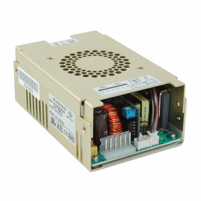
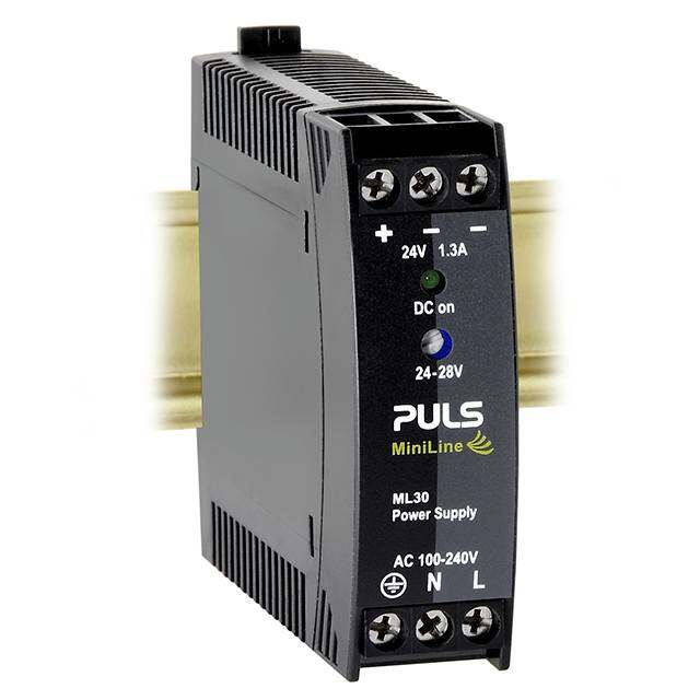
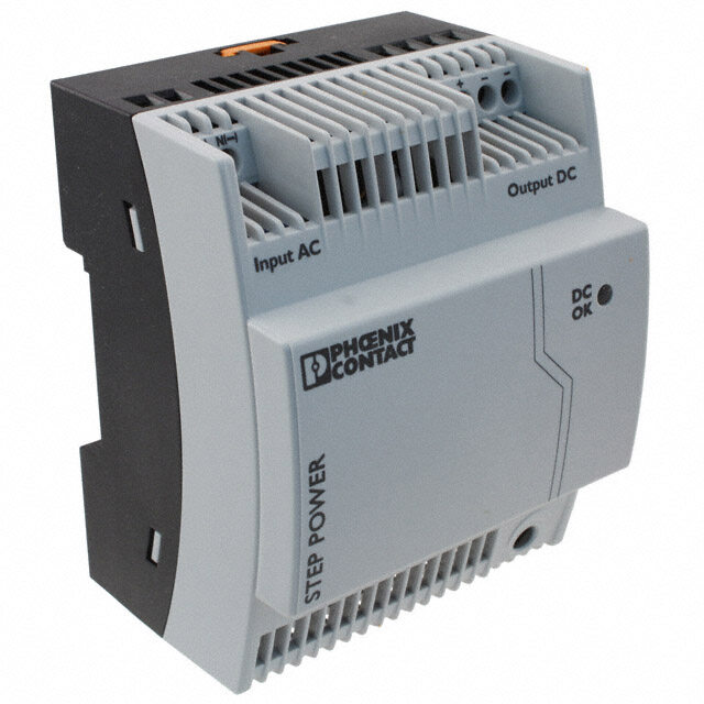
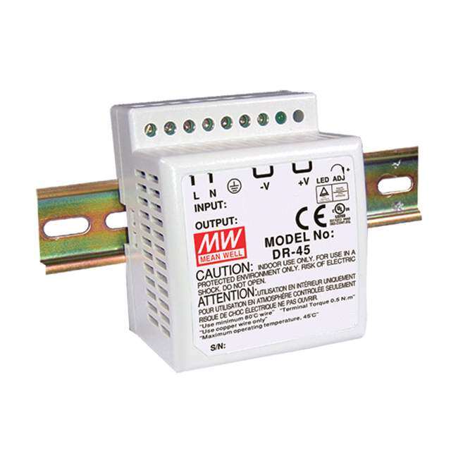
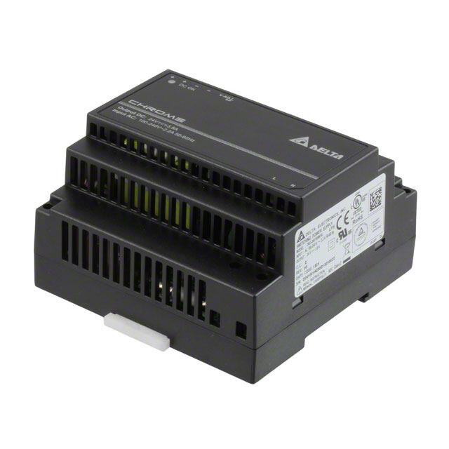
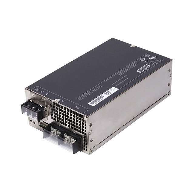
ICGOO电子元器件商城为您提供2902991由Phoenix Contact设计生产,在icgoo商城现货销售,并且可以通过原厂、代理商等渠道进行代购。 2902991价格参考。Phoenix Contact2902991封装/规格:AC DC 转换器, 封闭式 AC DC 转换器 1 输出 24V 1.25A 85 ~ 264 VAC 输入。您可以下载2902991参考资料、Datasheet数据手册功能说明书,资料中有2902991 详细功能的应用电路图电压和使用方法及教程。
Phoenix Contact的型号2902991属于AC/DC转换器,广泛应用于工业自动化领域。该产品主要用于将交流电(AC)转换为稳定直流电(DC),以供各类工业设备使用。其典型应用场景包括:

1. 工业控制系统:用于PLC、HMI和工控机等设备供电,确保系统稳定运行。
2. 机械制造:为机床、装配线设备提供可靠电源,适应复杂电磁环境。
3. 楼宇自动化:支持暖通空调、照明控制及安防系统的电力需求。
4. 能源与基础设施:适用于风力发电、智能电网等场景,保障关键设备持续供电。

该转换器具备高效率、宽输入电压范围及过载/短路保护功能,适合严苛工业环境,助力提升系统稳定性与安全性。
| 参数 | 数值 |
| 产品目录 | |
| 描述 | AC/DC CONVERTER 24V 30WDIN导轨式电源 UNO-PS/1AC/24DC/30W PRIM SWCH SNGL PHASE |
| 产品分类 | |
| 品牌 | Phoenix Contact |
| 产品手册 | http://www.phoenixcontact.com/gb/products/2902992/pdf |
| 产品图片 |
|
| rohs | 符合RoHS无铅 / 符合限制有害物质指令(RoHS)规范要求 |
| 产品系列 | 电源,DIN导轨式电源,Phoenix Contact 2902991UNO |
| 数据手册 | |
| 产品型号 | 2902991 |
| 产品 | Switching Supplies |
| 产品种类 | DIN导轨式电源 |
| 其它名称 | 277-9821 |
| 功率(W) | 30W |
| 功率(W)-最大值 | 30W |
| 商标 | Phoenix Contact |
| 商用/医用 | Commercial |
| 大小/尺寸 | 3.54" 长 x 0.89" 宽 x 3.54" 高 (90.0mm x 22.5mm x 90.0mm) |
| 安装类型 | DIN 轨道 |
| 安装风格 | DIN Rail |
| 尺寸 | 84 mm L x 22.5 mm W |
| 工作温度 | -25°C ~ 70°C |
| 应用 | ITE(商业) |
| 开放式框架/封闭式 | Enclosed |
| 所需最小负载 | - |
| 效率 | 88% |
| 标准包装 | 1 |
| 特性 | 可调输出,负载均分,通用输入 |
| 特色产品 | http://www.digikey.cn/product-highlights/zh/uno-power-supplies/50234 |
| 电压-输入 | 85 ~ 264 VAC |
| 电压-输出1 | 24V |
| 电压-输出2 | - |
| 电压-输出3 | - |
| 电压-输出4 | - |
| 电压-隔离 | 4kV(4000V) |
| 电流-输出(最大值) | 1.25A |
| 类型 | 封闭式 |
| 系列 | UNO-PS |
| 认可 | CB |
| 输入电压 | 85 VAC to 264 VAC |
| 输入类型 | 1-Phase / Single Phase |
| 输出功率额定值 | 30 W |
| 输出数 | 1 |
| 输出电压—通道1 | 24 VDC |
| 输出电流—通道1 | 1.25 A |
| 输出端数量 | 1 |
| 输出类型 | DC |
| 零件号别名 | UNO-PS/1AC/24DC/_30W UNOPS1AC24DC30W |


- 商务部:美国ITC正式对集成电路等产品启动337调查
- 曝三星4nm工艺存在良率问题 高通将骁龙8 Gen1或转产台积电
- 太阳诱电将投资9.5亿元在常州建新厂生产MLCC 预计2023年完工
- 英特尔发布欧洲新工厂建设计划 深化IDM 2.0 战略
- 台积电先进制程称霸业界 有大客户加持明年业绩稳了
- 达到5530亿美元!SIA预计今年全球半导体销售额将创下新高
- 英特尔拟将自动驾驶子公司Mobileye上市 估值或超500亿美元
- 三星加码芯片和SET,合并消费电子和移动部门,撤换高东真等 CEO
- 三星电子宣布重大人事变动 还合并消费电子和移动部门
- 海关总署:前11个月进口集成电路产品价值2.52万亿元 增长14.8%
PDF Datasheet 数据手册内容提取
UNO-PS/1AC/24DC/30W Primary-switched power supply unit Data sheet 105516_en_00 © PHOENIX CONTACT 2013-04-04 1 Description The UNO POWER power supply unit impresses in world- Features wide use thanks to maximum energy efficiency. Low no- – Worldwide use thanks to input voltage range of load losses and the high degree of efficiency save energy. 85 V AC ... 264 V AC Thanks to its high power density, the UNO POWER power – Maximum system availability through reliable power supply unit is the ideal solution, particularly in compact con- supply with 24 V DC trol boxes. – Maximum energy efficiency thanks to optimized efficiency over the entire operating range of the power supply unit and low no-load losses – Particularly compact: 30 W of power from this narrow power supply unit, which is just 22.5 mm wide Make sure you always use the latest documentation. It can be downloaded from the product at phoenixcontact.net/products.
UNO-PS/1AC/24DC/30W 2 Table of contents 1 Description..............................................................................................................................1 2 Table of contents.....................................................................................................................2 3 Ordering data ..........................................................................................................................3 4 Technical data.........................................................................................................................4 5 Intended use............................................................................................................................7 6 Structure..................................................................................................................................7 6.1 Device elements..................................................................................................................7 6.2 Block diagram.....................................................................................................................7 7 Assembly.................................................................................................................................8 7.1 Unpacking.........................................................................................................................8 7.2 Mounting the power supply unit...............................................................................................8 7.3 Mounting on a DIN rail.........................................................................................................10 7.4 Normal mounting position....................................................................................................10 8 Installing the power supply unit..............................................................................................11 8.1 Safety regulations and installation notes..................................................................................11 8.2 Mains connection..............................................................................................................11 8.3 Device connections............................................................................................................12 8.4 Connecting cables.............................................................................................................12 9 Operating behavior of the power supply unit..........................................................................13 9.1 Normal operation...............................................................................................................13 9.2 Overload response.............................................................................................................13 9.3 Behavior at ambient temperatures > 55°C................................................................................13 9.4 Behavior in the case of alternative mounting positions.................................................................14 10 Operating the power supply unit............................................................................................17 10.1 Function monitoring............................................................................................................17 10.2 Operating power supply units in parallel..................................................................................18 10.3 Operating the power supply unit in series.................................................................................19 11 Removal................................................................................................................................19 11.1 Removing the power supply unit............................................................................................19 11.2 Notes on disposal..............................................................................................................19 105516_en_00 PHOENIX CONTACT 2
UNO-PS/1AC/24DC/30W 3 Ordering data Description Type Order No. Pcs. / Pkt. DIN rail power supply unit 24 V DC/30 W, primary-switched, single-phase UNO-PS/1AC/24DC/30W 2902991 1 Accessories Type Order No. Pcs. / Pkt. Redundancy module, 5-24 V DC, 2x 5 A, 1x 10 A STEP-DIODE/5-24DC/2X5/1X10 2868606 1 Our range of accessories is being continually extended, our current range can be found in the download area. 105516_en_00 PHOENIX CONTACT 3
UNO-PS/1AC/24DC/30W 4 Technical data Input data Nominal input voltage range 100 V AC ... 240 V AC AC input voltage range 85 V AC ... 264 V AC AC frequency range 45 Hz ... 65 Hz Current consumption 0.5 A (120 V AC) 0.3 A (230 V AC) Inrush current limitation < 20 A (typical) I2t < 0.4 A2s Typical response time < 1 s Power failure bypass > 25 ms (120 V AC) > 115 ms (230 V AC) Protective circuit Transient surge protection Varistor Input fuse, integrated 2 A (slow-blow, internal) Choice of suitable fuses 6 A ... 16 A (Characteristics B, C, D, K) Input connection data Connection method Screw connection Conductor cross section, solid 0.2 mm² ... 2.5 mm² Conductor cross section, stranded 0.2 mm² ... 2.5 mm² Conductor cross section AWG/kcmil 24 ... 14 Stripping length 8 mm Screw thread M3 Tightening torque 0.5 Nm ... 0.6 Nm Output data Nominal output voltage 24 V DC ±1% Output current 1.25 A (-25°C ... 55°C) Derating 55 °C ... 70 °C (2.5%/K) Control deviation < 1 % (change in load, static 10% ... 90%) < 2 % (Dynamic load change 10% ... 90%, 10 Hz) < 0.1 % (change in input voltage ±10%) Ascent time < 0.5 s (UOUT (10% ... 90%)) Residual ripple < 60 mVPP (with nominal values) Connection in parallel yes, with redundancy module Connection in series Yes Protection against surge voltage on the output ≤ 35 V DC Resistance to reverse feed < 35 V DC Output connection data Connection method Screw connection Conductor cross section, solid 0.2 mm² ... 2.5 mm² Conductor cross section, stranded 0.2 mm² ... 2.5 mm² Conductor cross section AWG/kcmil 24 ... 14 Connection method 8 mm Screw thread M3 Tightening torque 0.5 Nm ... 0.6 Nm 105516_en_00 PHOENIX CONTACT 4
UNO-PS/1AC/24DC/30W Power consumption Efficiency > 88 % (for 230 V AC and nominal values) Maximum power dissipation NO-Load < 0.3 W Power loss nominal load max. < 5 W General data Insulation voltage input/output 4 kV AC (type test) 3 kV AC (routine test) MTBF > 500000 h (According to EN 29500) Housing material polycarbonate Foot latch material Plastic POM Dimensions W / H / D 22.5 mm / 90 mm / 84 mm Weight 0.15 kg Security Degree of protection IP20 Protection class II (in an enclosed control cabinet) SELV IEC 60950-1 (SELV) and EN 60204 (PELV) Ambient conditions Ambient temperature (operation) -25 °C ... 70 °C (> 55° C derating) Ambient temperature (storage/transport) -40 °C ... 85 °C Max. permissible relative humidity (operation) ≤ 95 % (at 25 °C, no condensation) Vibration (operation) < 15 Hz, amplitude ±2.5 mm (according to IEC 60068-2-6) 15 Hz ... 150 Hz, 2.3g, 90 min. Shock 30 g in each direction, according to IEC 60068-2-27 Pollution degree 2 Climatic class 3K3 (in acc. with EN 60721) Inflammability class in acc. with UL 94 (housing) V0 Standards Electrical Equipment for Machinery EN 60204-1 Electrical safety (of information technology equipment - Safety - Part 1) IEC 60950-1/VDE 0805 (SELV) Electronic equipment for use in electrical power installations EN 50178/VDE 0160 (PELV) SELV IEC 60950-1 (SELV) and EN 60204 (PELV) Safe isolation DIN VDE 0100-410 Protection against electric shock DIN 57100-410 Limitation of mains harmonic currents EN 61000-3-2 Network version/undervoltage EN 61000-4-11 Information technology equipment - Safety (CB Scheme) CB Scheme Approvals UL approvals UL/C-UL listed UL 508 UL/C-UL Recognized UL 60950 NEC Class 2 as per UL 1310 CSA CAN/CSA-C22.2 No. 60950-1-07 CSA-C22.2 No. 107.1-01 105516_en_00 PHOENIX CONTACT 5
UNO-PS/1AC/24DC/30W Conformance with EMC Directive 2004/108/EC Noise immunity according to EN 61000-6-2 EN 61000-6-2 requirement Tested Electrostatic discharge EN 61000-4-2 Housing contact discharge 4 kV (Test intensity 2) 6 kV (Test intensity 3) Housing air discharge 8 kV (Test intensity 3) 8 kV (Test intensity 3) Comments Criterion B Criterion B Electromagnetic HF field EN 61000-4-3 Frequency range 80 MHz ... 1 GHz 80 MHz ... 1 GHz Test field strength 10 V/m 10 V/m Frequency range 1.4 GHz ... 2 GHz 1 GHz ... 2 GHz Test field strength 3 V/m 10 V/m Frequency range 2 GHz ... 2.7 GHz 2 GHz ... 3 GHz Test field strength 1 V/m 10 V/m Comments Criterion A Criterion A Fast transients (burst) EN 61000-4-4 Input 2 kV (Test intensity 3 - asymmetrical) 4 kV (Test intensity 4 - asymmetrical) Output 2 kV (Test intensity 3 - asymmetrical) 2 kV (Test intensity 3 - asymmetrical) Comments Criterion B Criterion A Surge current loads (surge) EN 61000-4-5 Input 1 kV (Test intensity 2 - symmetrical) 2 kV (Test intensity 3 - symmetrical) 2 kV (Test intensity 3 - asymmetrical) 4 kV (Test intensity 4 - asymmetrical) Output 0.5 kV (Test intensity 1 - symmetrical) 1 kV (Test intensity 2 - symmetrical) 0.5 kV (Test intensity 1 - asymmetrical) 2 kV (Test intensity 3 - asymmetrical) Comments Criterion B Criterion A Conducted interference EN 61000-4-6 Frequency range 10 kHz ... 80 MHz 10 kHz ... 80 MHz Voltage 10 V (Test intensity 3) 10 V (Test intensity 3) Comments Criterion A Criterion A Criterion A Normal operating behavior within the specified limits. Criterion B Temporary impairment to operational behavior that is corrected by the device it- self. Emitted interference in acc. with EN 61000-6-3 Radio interference voltage in acc. with EN 55011 EN 55011 (EN 55022) class B used in industry and residential area / EMC 1 Emitted radio interference in acc. with EN 55011 EN 55011 (EN 55022) class B used in industry and residential area / EMC 1 All technical specifications are nominal values and refer to a room temperature of 25°C and 70% relative hu- midity at 100 m above sea level. Current approvals can be found for the product in the download area. 105516_en_00 PHOENIX CONTACT 6
UNO-PS/1AC/24DC/30W 5 Intended use This power supply unit features IP20 protection and is in- tended for installation in housing. It is suitable for use in in- dustrial applications. 6 Structure 6.1 Device elements 6.2 Block diagram 2 L + N - 3 Element Meaning 4 Fuse Decoupling 1 Figure 1 Device elements Switch 1. Input voltage: Input AC L/N 2. Output voltage: Output DC+/- Transmitter 3. Green LED: DC OK 4. Universal snap-on foot: 35 mm DIN rail according to EN 60715 Filter Disconnect transducer Controller 105516_en_00 PHOENIX CONTACT 7
UNO-PS/1AC/24DC/30W 7 Assembly 7.1 Unpacking Before mounting the power supply unit, it must be checked for damage: – Take the device out of its packaging. – Check the device for any damage sustained during transport. – Retain the package slip for future use. – Dispose of packaging in an environmentally-friendly way. 7.2 Mounting the power supply unit The power supply unit is intended for installa- tion in a distributor box or control cabinet. The power supply unit is designed for convec- tion cooling. Maintain a minimum distance from other devices in order to ensure convec- tion cooling. Figure 2 Convection 105516_en_00 PHOENIX CONTACT 8
UNO-PS/1AC/24DC/30W Please note the following before mounting the power supply unit: – The minimum distance from other devices that must be observed in order to ensure convection cooling is: 30 mm vertically, 0 mm horizontally 0 3 5 7 0 5 1 – The device dimensions 90 22,5 84 0 9 58 63 7 2 8 0 7 12 5 105516_en_00 PHOENIX CONTACT 9
UNO-PS/1AC/24DC/30W 7.3 Mounting on a DIN rail The power supply unit can be installed on all 35 mm DIN rails according to EN 60175. A B Figure 3 Mounting on a DIN rail 7.4 Normal mounting position When installed, the input terminal blocks must be at the bot- tom and the output terminal blocks at the top. If the power supply unit is installed in a mounting position other than the normal mounting position, the output power must be reduced. Figure 4 Normal mounting position 105516_en_00 PHOENIX CONTACT 10
UNO-PS/1AC/24DC/30W 8 Installing the power supply unit 8.1 Safety regulations and installation notes 8.2 Mains connection The device can be connected to single-phase AC or three- WARNING: risk of electric shock! phase power grids (TN-S, TN-C, TT, and IT) while consider- Only qualified specialist personnel may in- ing the nominal input voltage. stall, start up, and operate the device. Ob- serve the national safety and accident For operation on two of the phase conductors prevention regulations. of a three-phase system, an isolating facility Prior to installation, disconnect the input volt- for all poles must be provided. age and make sure that it cannot be switched on again unintentionally. TN-S TN-C Mains connection must be performed by spe- cialist personnel and protection against elec- L L N PEN tric shock ensured. PE Make sure that the device can be switched off outside the power supply according to the regulations in EN 60950 (e.g., by line protec- L N L N tion on the primary side). + - + - Cover termination area after installation in or- der to avoid accidental contact with live parts TT iT (e.g., by installing in a control cabinet). L1 Protect the device against ingress by foreign L L2 bodies, e.g., paper clips or metal parts. N L3 WARNING: Make sure that all supply lines are sufficiently L N L N dimensioned and have sufficient fuse protec- + - + - tion. Make sure that all output cables are dimen- Figure 5 Network types sioned accordingly for the maximum device output current or have separate fuse protec- tion. NOTE: Never open or repair the device yourself. Internal fuses will only blow in the event of de- vice malfunction. Do not modify or attempt to repair the device. Send the device to the fac- tory for examination. 105516_en_00 PHOENIX CONTACT 11
UNO-PS/1AC/24DC/30W 8.3 Device connections 8.4 Connecting cables Screw connection for input AC L/N Use copper cables with an operating temper- ature > 75°C (ambient temperature < 55°C) and > 90°C (ambient temperature < 75°C). Figure 6 Screw connection for input AC L/N Screw connection for output DC +/- Figure 8 Connecting cables 1. Connect the supply lines to the input AC L/N connection terminal blocks. Figure 7 Screw connection for output DC +/- 2. Connect the output cables to the output DC +/- connec- tion terminal blocks. The power supply unit is operational as soon as the input ter- minal blocks are supplied with voltage. 105516_en_00 PHOENIX CONTACT 12
UNO-PS/1AC/24DC/30W 9 Operating behavior of the power supply unit 9.1 Normal operation In normal operation, the loads are supplied with a constant output voltage of 24 V DC. 9.2 Overload response In the event of overload (I > I ), the device reduces its output N voltage. If the output voltage is greater than U x 0.9, the N green DC OK LED lights up. If the output voltage drops below U x 0.5, the device shuts down. After a short time, N the device attempts to start up again. If the overload has been rectified, it will start up as normal. If the overload has still not been rectified, it will shut down again and attempt to restart again (automatic restart). V] UN [ UN x 0,5 IN [A] Figure 9 Output characteristic curve 9.3 Behavior at ambient temperatures > 55°C At an ambient temperature of up to 55°C, the power supply unit supplies the nominal output current. At ambient temper- atures upwards of 55°C, the output power must be reduced by 2.5% per Kelvin temperature increase (temperature-de- pendent derating). A] [ I N 0 -25 20 40 60 [°C] Figure 10 Temperature-dependent derating 105516_en_00 PHOENIX CONTACT 13
UNO-PS/1AC/24DC/30W 9.4 Behavior in the case of alternative mounting positions For mounting positions that differ from the normal mounting position, the output power must be reduced (position-de- pendent derating). The characteristic curve can be used to determine the max- imum output power to be drawn for each ambient tempera- ture for different mounting positions. Normal mounting position %] 110 [ 100 90 80 70 60 50 40 0 -25 25 35 45 55 65 75 [°C] Y Z X Rotated mounting position 90° X-axis %] 110 [ 100 90 80 70 60 50 40 0 -25 25 35 45 55 65 75 [°C] Y Z X 105516_en_00 PHOENIX CONTACT 14
UNO-PS/1AC/24DC/30W Rotated mounting position 180° X-axis %] 110 [ 100 90 80 70 60 50 40 0 -25 25 35 45 55 65 75 [°C] Y Z X Rotated mounting position 270° X-axis %] 110 [ 100 90 80 70 60 50 40 0 -25 25 35 45 55 65 75 [°C] Y Z X 105516_en_00 PHOENIX CONTACT 15
UNO-PS/1AC/24DC/30W Rotated mounting position 90° Z-axis %] 110 [ 100 90 80 70 60 50 40 0 -25 25 35 45 55 65 75 [°C] Y Z X Rotated mounting position 270° Z-axis %] 110 [ 100 90 80 70 60 50 40 0 -25 25 35 45 55 65 75 [°C] Y Z X 105516_en_00 PHOENIX CONTACT 16
UNO-PS/1AC/24DC/30W 10 Operating the power supply unit 10.1 Function monitoring DC OK LED The DC OK LED is available for visual function monitoring of the power supply unit. Status 1 Status 2 DC OK LED Lit OFF Meaning Output voltage > 21.5 V Output voltage < 21.5 V DC, overload mode or no mains voltage State description The device is operating, output voltage and The device is in operation, but there is a fault on the side output current are OK of the consumer; the current consumption is greater than IN or the output is short-circuited. The device is out of operation because there is no mains voltage, the fuse on the primary side has been triggered, or the device is faulty. Remedy Remove the error at the load, use a more powerful power supply unit, connect a power supply unit of the same type parallel to the existing device, remove the short circuit, apply mains voltage, enable the fuse again or replace the power supply unit. 105516_en_00 PHOENIX CONTACT 17
UNO-PS/1AC/24DC/30W 10.2 Operating power supply units in parallel Power supply units of the same type can be connected in Increased performance parallel to increase both redundancy and power. Power supply units of the same type can be connected in parallel to increase the power to n x I . Parallel connection N To ensure symmetrical current distribution, all is recommended if existing systems are to be extended and cable connections from the power supply unit the power supply unit that is installed here does not cover to the busbar must be the same length and the current consumption of the most powerful load. Other- have the same conductor cross section. wise, the loads should be distributed between individual de- vices that are independent of one another. Using a redundancy module, it is possible for two power Redundant operation supply units of the same type that are connected in parallel Redundant circuits are suitable for supplying systems which on the output side to increase power to be decoupled from place particularly high demands on operational safety. If a one another. fault occurs in the primary circuit of the first power supply unit, the second device automatically takes over the com- I I plete power supply without interruption, and vice versa. N N + − + − Using a redundancy module, it is possible for two power supply units of the same type that are connected in parallel on the output side for redundancy to be decoupled from one another. + − I I N N + − + − Σ= 2 x I + − N + Figure 12 Parallel connection to increase power with a − redundancy module Σ= I N + − Figure 11 Redundant circuit with redundancy module 105516_en_00 PHOENIX CONTACT 18
UNO-PS/1AC/24DC/30W 10.3 Operating the power supply unit in series 11 Removal Two devices can be connected in series to double the volt- age. Only power supply units of the same type should be 11.1 Removing the power supply unit connected in series. Series connection should always be used when the output voltage of the module is not sufficient. For example, devices with 24 V DC nominal output voltage each supply 48 V DC in series. Depending on the specifica- tion of functional earth ground, output voltages of + 48 V/- 48 V as well as ±24 V DC can also be made available. + + + - - +24 V - A B +48 V -48 V Figure 14 Removal + + -24 V + 11.2 Notes on disposal - - - Do not dispose of the power supply unit with household waste. It should be disposed of in Figure 13 Series operation accordance with the currently applicable na- tional regulations. 105516_en_00 PHOENIX CONTACT GmbH & Co. KG • 32823 Blomberg • Germany 19 www.phoenixcontact.com