ICGOO在线商城 > 电路保护 > PTC 可复位保险丝 > 2016L050MR
 Datasheet下载
- 型号: 2016L050MR
- 制造商: Littelfuse
- 库位|库存: xxxx|xxxx
- 要求:
| 数量阶梯 | 香港交货 | 国内含税 |
| +xxxx | $xxxx | ¥xxxx |
查看当月历史价格
查看今年历史价格
2016L050MR产品简介:
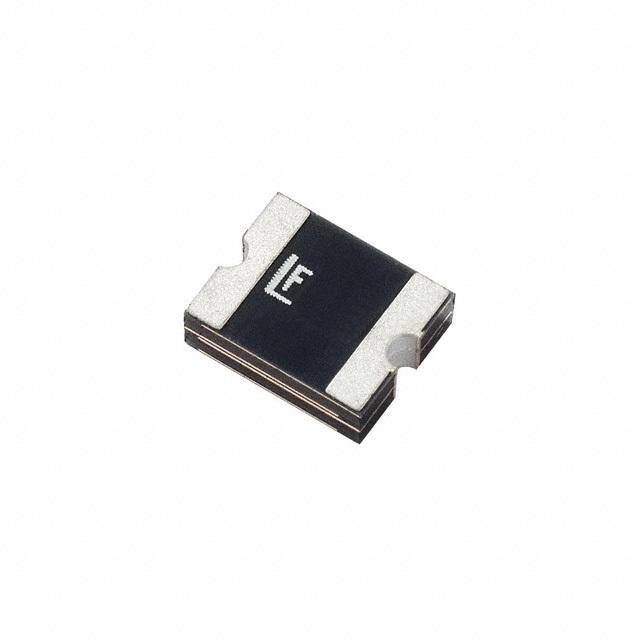
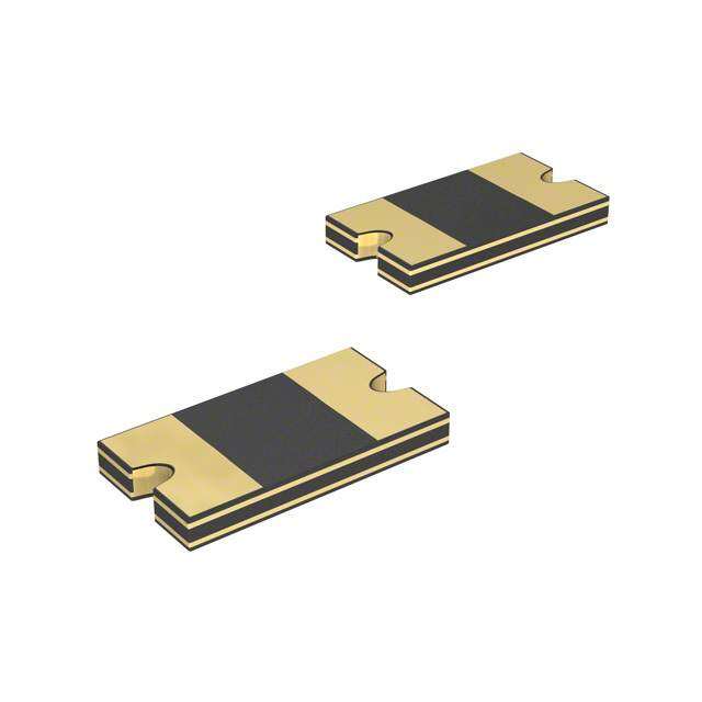
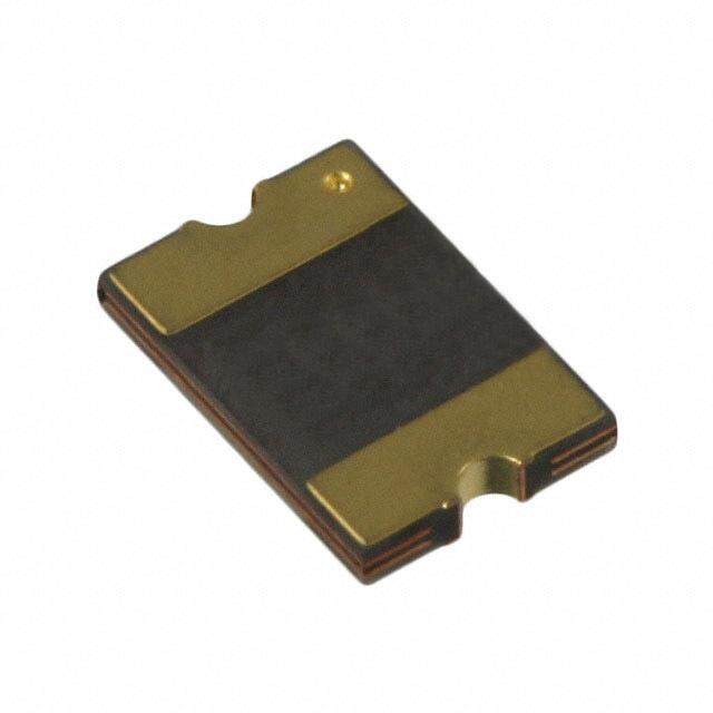
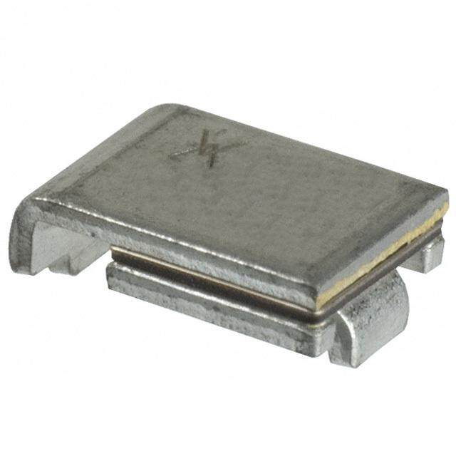
ICGOO电子元器件商城为您提供2016L050MR由Littelfuse设计生产,在icgoo商城现货销售,并且可以通过原厂、代理商等渠道进行代购。 2016L050MR价格参考。Littelfuse2016L050MR封装/规格:PTC 可复位保险丝, Polymeric PTC Resettable Fuse 60V 550mA Ih Surface Mount 2016 (5041 Metric), Concave。您可以下载2016L050MR参考资料、Datasheet数据手册功能说明书,资料中有2016L050MR 详细功能的应用电路图电压和使用方法及教程。
Littelfuse Inc. 的 2016L050MR 是一款表面贴装(SMD)的 PTC 可复位保险丝,额定电压为30V,保持电流为0.5A。该器件主要用于电路过流保护,能够在异常电流出现时迅速升温并进入高阻态,切断或限制电流,故障排除后自动恢复,无需更换元件。

典型应用场景包括:

1. 消费类电子产品:广泛用于智能手机、平板电脑、蓝牙耳机、移动电源等设备中,保护USB接口、充电电路及小型电池组免受短路或过流损坏。

2. 便携式设备:适用于数码相机、电子书阅读器、智能手表等对空间要求严格的设备,其小型化尺寸(约2016封装)便于集成。

3. 通信设备:用于保护数据线、通信模块(如Wi-Fi、蓝牙模块)中的电源线路,防止因误插或静电引发的电流冲击。

4. 工业与家电控制板:在小型电机驱动、传感器供电、LED驱动电源等低压直流电路中提供可靠的可复位保护。

5. 电池管理系统(BMS):常用于锂离子或锂聚合物电池组中,配合保护IC使用,增强过流和短路防护能力,提高系统安全性。

2016L050MR 具有响应快、寿命长、自恢复等优点,特别适合需要高可靠性和维护便利性的应用场合。其无铅设计也符合RoHS环保标准,适用于现代绿色电子产品制造。
| 参数 | 数值 |
| 产品目录 | |
| 描述 | PTC RESETTABLE 60V .55A 2016 SMD可复位保险丝—PPTC 60V 2016 .550A POLYFUSE |
| 产品分类 | |
| 品牌 | Littelfuse Inc |
| 产品手册 | |
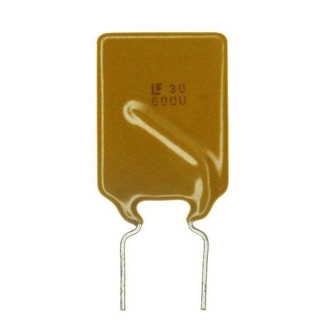
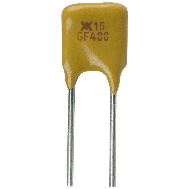
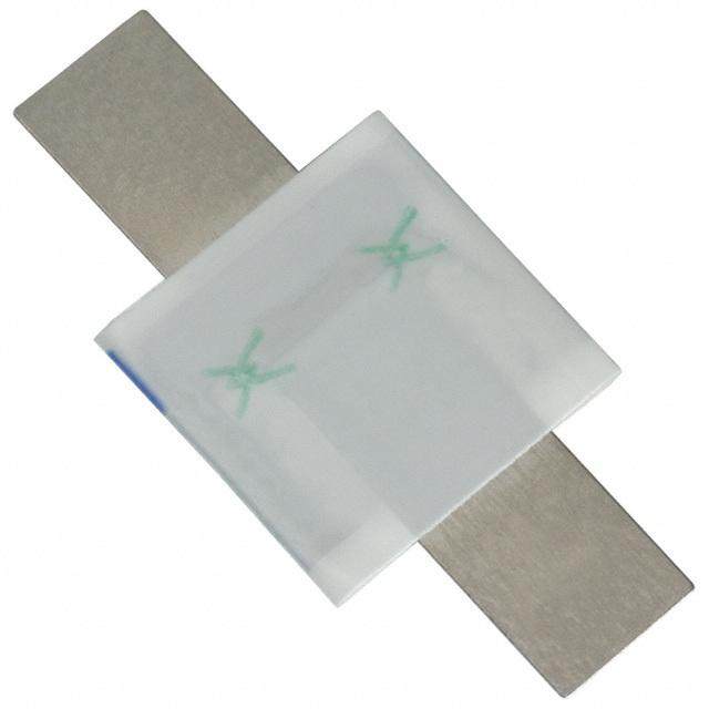
| 产品图片 |
|
| rohs | 符合RoHS无铅 / 符合限制有害物质指令(RoHS)规范要求 |
| 产品系列 | Littelfuse 2016L050MRPOLYFUSE® 2016L |
| mouser_ship_limit | 该产品可能需要其他文件才能进口到中国。 |
| 数据手册 | |
| 产品型号 | 2016L050MR |
| R(最小/最大值) | 0.200 ~ 1.000 欧姆 |
| 产品种类 | 可复位保险丝—PPTC |
| 保持电流 | 0.55 A |
| 其它名称 | F4070DKR |
| 包装 | Digi-Reel® |
| 商标 | Littelfuse |
| 安装风格 | SMD/SMT |
| 封装 | Reel |
| 封装/外壳 | 2016(5041 公制),凹陷 |
| 封装/箱体 | 2016 (5041 metric) |
| 尺寸 | 4.72 mm L x 3.7 mm W x 1.2 mm H |
| 工作温度范围 | - 40 C to + 85 C |
| 工具箱 | /product-detail/zh/00940505Z/00940505Z-ND/2519714 |
| 工厂包装数量 | 1000 |
| 最大电压 | 60 VDC |
| 标准包装 | 1 |
| 电压-最大值 | 60V |
| 电流-保持(Ih)(最大值) | 550mA |
| 电流-最大值 | 20A |
| 电流-跳闸(It) | 1.1A |
| 电阻 | 1 Ohms |
| 端接类型 | SMD/SMT |
| 类型 | PolyFuse Resettable PTC |
| 系列 | 2016L |
| 跳闸时间 | 5s |
| 跳闸电流 | 1.1 A |
| 额定电流—最大值 | 20 A |


- 商务部:美国ITC正式对集成电路等产品启动337调查
- 曝三星4nm工艺存在良率问题 高通将骁龙8 Gen1或转产台积电
- 太阳诱电将投资9.5亿元在常州建新厂生产MLCC 预计2023年完工
- 英特尔发布欧洲新工厂建设计划 深化IDM 2.0 战略
- 台积电先进制程称霸业界 有大客户加持明年业绩稳了
- 达到5530亿美元!SIA预计今年全球半导体销售额将创下新高
- 英特尔拟将自动驾驶子公司Mobileye上市 估值或超500亿美元
- 三星加码芯片和SET,合并消费电子和移动部门,撤换高东真等 CEO
- 三星电子宣布重大人事变动 还合并消费电子和移动部门
- 海关总署:前11个月进口集成电路产品价值2.52万亿元 增长14.8%

PDF Datasheet 数据手册内容提取
POLY-FUSE® Resettable PTCs Surface Mount > 2016L Series 2016L Series RoHS Description The 2016L Series PTC provides surface mount overcurrent protection for low voltage (≤60V) applications where resettable protection is desired. Features • RoHS compliant, lead-free • High voltage and halogen-free • Low-profile • Fast response to fault currents Agency Approvals Applications • IEEE 1394 port protection • Low voltage telecom AGENCY AGENCY FILE NUMBER • Powered ethernet port equipment protection E183209 protection (IEEE 802.3 af) • Automotive electronic R50119118 control module protection Electrical Characteristics Maximum Time Agency Resistance I I V I P typ. To Trip Approvals Part Number Marking hold trip max max d (A) (A) (Vdc) (A) (W) Current Time R R min 1max (A) (Sec.) (Ω) (Ω) 2016L030 LF030 0.30 0.60 60 20 1.40 1.5 3.0 0.500 2.300 X X 2016L050 LF050 0.55 1.10 60 20 1.40 2.5 5.0 0.200 1.000 X X 2016L075/60 LF075 0.75 1.50 60 20 1.40 8.0 0.5 0.130 0.900 X X 2016L100 LF100 1.10 2.20 15 40 1.40 8.0 0.5 0.100 0.400 X X 2016L100/33 LF100-33 1.10 2.20 33 40 1.40 8.0 0.5 0.100 0.400 X X 2016L150 LF150 1.50 3.00 15 40 1.40 8.0 1.0 0.070 0.180 X X 2016L150/33 LF150-33 1.50 3.00 33 40 2.0 8.00 1.00 0.070 0.180 X X 2016L200 LF200 2.00 4.20 6 40 1.40 8.0 3.0 0.048 0.100 X X 2016L260/24 LF260-24 2.60 5.00 24 40 1.6 8.00 5.00 0.025 0.075 X X 2016L300/16 LF300 3.00 5.00 16 40 1.6 8.00 10.00 0.015 0.048 X X 2016L500 LF500 5.00 10.00 6 100 2.0 25.00 2.00 0.005 0.025 X X I = Hold current: maximum current device will pass without tripping in 20°C still air. hold I = Trip current: minimum current at which the device will trip in 20°C still air. trip V = Maximum voltage device can withstand without damage at rated current (I max) max I = Maximum fault current device can withstand without damage at rated voltage (V ) max max P = Power dissipated from device when in the tripped state at 20°C still air. d R = Minimum resistance of device in initial (un-soldered) state. min R = Typical resistance of device in initial (un-soldered) state. typ R = M aximum resistance of device at 20°C measured one hour after tripping or reflow soldering of 260°C for 20 sec. 1max Caution: Operation beyond the specified rating may result in damage and possible arcing and flame. * Agency Approval is Pending WARNING • Users shall independently assess the suitability of these devices for each of their applications • Operation of these devices beyond the stated maximum ratings could result in damage to the devices and lead to electrical arcing and/or fire • These devices are intended to protect against the effects of temporary over-current or over-temperature conditions and are not intended to perform as protective devices where such conditions are expected to be repetitive or prolonged in duration • Exposure to silicon-based oils, solvents, electrolytes, acids, and similar materials can adversely affect the performance of these PPTC devices • These devices undergo thermal expansion under fault conditions, and thus shall be provided with adequate space and be protected against mechanical stresses • Circuits with inductance may generate a voltage (L di/dt) above the rated voltage of the PPTC device. © 2017 Littelfuse, Inc. Specifications are subject to change without notice. Revised: 11/13/17
POLY-FUSE® Resettable PTCs Surface Mount > 2016L Series Temperature Rerating Ambient Operation Temperature -40°C -20°C 0°C 20°C 40°C 50°C 60°C 70°C 85°C Part Number Hold Current (A) 2016L030 0.45 0.40 0.35 0.30 0.25 0.23 0.20 0.18 0.14 2016L050 0.93 0.80 0.65 0.55 0.42 0.38 0.33 0.30 0.23 2016L075/60 1.21 1.06 0.91 0.75 0.61 0.54 0.45 0.38 0.26 2016L100 1.66 1.47 1.29 1.10 0.91 0.83 0.73 0.64 0.50 2016L100/33 1.66 1.47 1.29 1.10 0.91 0.83 0.73 0.64 0.50 2016L150 2.26 2.00 1.76 1.50 1.24 1.13 1.00 0.87 0.68 2016L150/33 2.25 2.05 1.79 1.50 1.31 1.17 1.05 0.93 0.72 2016L200 2.80 2.50 2.19 2.00 1.84 1.74 1.50 1.34 1.14 2016L260/24 3.80 3.43 3.04 2.60 2.24 2.03 1.82 1.64 1.25 2016L300/16 4.32 3.93 3.57 3.00 2.58 2.40 2.22 1.89 1.68 2016L500 7.20 6.55 5.95 5.00 4.30 4.00 3.70 3.15 2.80 Average Time Current Curves Temperature Rerating Curve 170% AAA/60AA/33AA A/33A/24A/16A 150% 100 0.300.500.751.001.001.502.00 1.502.603.005.00 Percentage of Rated Current 111579300000%%%%% 10 s d 30% n o ec 10% S n -40 -30 -20 -10 0 10 20 30 40 50 60 70 8085 e i 1 Temperature (°C) m Ti Note: Typical Temperature rerating curve, refer to table for derating data 0.1 Additional Information 0.01 0.1 1 10 Current in Amperes Datasheet Resources SSaammpplleess The average time current curves and Temperature Rerating curve performance is affected by a number or variables, and these curves provided as guidance only. Customer must verify the performance in their application. © 2017 Littelfuse, Inc. Specifications are subject to change without notice. Revised: 11/13/17
POLY-FUSE® Resettable PTCs Surface Mount > 2016L Series Soldering Parameters Profile Feature Pb-Free Assembly t P T Average Ramp-Up Rate (T to T) 3°C/second max P Critical Zone S(max) P RRaammpp--uupp tL to tP Temperature Min (T ) 150°C s(min) T L t Pre Heat: Temperature Max (Ts(max)) 200°C TS(max) L Time (Min to Max) (ts) 60 – 180 secs eru RRaammpp--ddoown Time Maintained Temperature (TL) 217°C tar T PPrreehheeaatt e S(min) Above: Temperature (tL) 60 – 150 seconds pm tS e Peak / Classification Temperature (T) 260+0/-5 °C T P 25 Time within 5°C of actual peak 20 – 40 seconds time to peak temperature Time Temperature (t) p Ramp-down Rate 6°C/second max -- All temperature refer to topside of the package, measured on the package body surface -- If reflow temperature exceeds the recommended profile, devices may not meet the Time 25°C to peak Temperature (T) 8 minutes Max. P performance requirements -- Recommended reflow methods: IR, vapor phase oven, hot air oven, N environment 2 for lead -- Recommended maximum paste thickness is 0.25mm (0.010 inch) -- Devices can be cleaned using standard industry methods and solvents -- Devices can be reworked using the standard industry practices Physical Specifications Environmental Specifications Solder-Plated Copper (Solder Material: Operating/Storage Terminal Material -40°C to +85°C Matte Tin(Sn)) Temperature Maximum Device Surface Meets EIA Specification RS186-9E, ANSI/ Lead Solderability Temperature in Tripped 125°C J-STD-002 Category 3. State +85°C, 1000 hours Passive Aging -/+5% typical resistance change +85°C, 85%,R.H.,1000 hours Humidity Aging -/+5% typical resistance change MIL–STD–202, Method 107 Thermal Shock +85°C/-40°C 20 times -30% typical resistance change MIL–STD–202, Method 215 Solvent Resistance No change MIL–STD–883, Method 2007, Vibration Condition A No change Moisture Sensitivity Level Level 1, J–STD–020 © 2017 Littelfuse, Inc. Specifications are subject to change without notice. Revised: 11/13/17
POLY-FUSE® Resettable PTCs Surface Mount > 2016L Series Dimensions (mm) A C MARKING CODE VARIES WITH AMPERAGE AND VOLTAGE RATING Top 100 100 Side SEE ELECTRICAL CHARACTERISTICS CHART View B -33 View S- 1H.1OAW/1N5 VA RREA:TING (LEFT) - 1.1A/33V RATING (RIGHT) 3.40 mm Bottom 100 Pad (.133”) 4.60 mm View Layout (.181”) D E 1.50 mm (.059”) A B C D E Part Inches mm Inches mm Inches mm Inches mm Inches mm Number Min Max Min Max Min Max Min Max Min Max Min Max Min Max Min Max Min Max Min Max 2016L030 0.03 0.05 0.75 1.25 2016L050 0.05 0.08 1.20 2.00 2016L075/60 0.05 0.08 1.20 2.00 4.43 2016L100 0.02 0.03 0.50 0.75 2016L100/33 0.03 0.05 0.75 1.25 2016L150 0.19 0.21 4.72 5.44 0.15 0.17 3.7 0.03 0.06 0.75 1.55 0.01 0.06 0.3 1.5 0.01 0.03 0.25 0.65 2016L150/33 4.43 0.03 0.06 0.80 1.60 2016L200 4.43 0.02 0.03 0.50 0.75 2016L260/24 2016L300/16 4.43 0.03 0.06 0.80 1.60 2016L500 Part Ordering Number System 2016 L xxx /xx D R- A -A: Automotive grade Blank: Standard version SERIES PACKAGING STYLE R: Tape & Reel QUANTITY CODE: D=1500 M=1000 P=2000 SPECIAL VOLTAGE RATING ITEM (Not applicable to all parts. Refer to Electrical Characteristics Table for additional information) I HOLD CURRENT CODE HOLD (Refer to Electrical Characteristics Table) L: LITTELFUSE SURFACE MOUNT PPTC DEVICE SIZE CODE (0.20 x 0.16 inch) Packaging Halogen I Voltage Packaging Quantity & Part Number Ordering Number hold I Code Quantity Free (A) hold Option Option Packaging Codes 2016L030 2016L030DR Yes 0.30 030 Tape and Reel 1500 DR 2016L050 2016L050MR Yes 0.55 050 Tape and Reel 1000 MR 2016L075/060 2016L075/60MR Yes 0.75 075 /60 Tape and Reel 1000 MR 2016L100 2016L100PR Yes 1.10 110 Tape and Reel 2000 PR 2016L100/33 2016L100/33DR Yes 1.10 110 /33 Tape and Reel 1500 DR 2016L150 2016L150DR Yes 1.50 150 Tape and Reel 1500 DR 2016L150/33 2016L150/33DR Yes 1.50 150 /33 Tape and Reel 1,500 DR 2016L200 2016L200PR Yes 2.00 200 Tape and Reel 2000 PR 2016L260/24 2016L260/24DR Yes 2.60 260 /24 Tape and Reel 1,500 DR 2016L300/16 2016L300/16MR Yes 3.00 300 /16 Tape and Reel 1,000 MR 2016L500 2016L500DR Yes 5.00 500 /6 Tape and Reel 1,500 DR © 2017 Littelfuse, Inc. Specifications are subject to change without notice. Revised: 11/13/17
POLY-FUSE® Resettable PTCs Surface Mount > 2016L Series Tape and Reel Specifications TAPE SPECIFICATIONS: EIA-481-1 (mm) 2016L030 2016L100/33 2016L150 REEL DIMENSIONS: 2016L100 2016L150/33 2016L050 EIA-481-1 (mm) 2016L200 2016L260/24 2016L075/60 2016L300/16 2016L500 W 12.0+/- 0.30 12.0+/- 0.30 12.0+/- 0.30 C Ø178.0+/-1.0 F 5.50+/- 0.05 5.50+/- 0.05 5.50+/- 0.05 D Ø60.2+/-0.5 E 1.75+/- 0.10 1.75+/- 0.10 1.75+/- 0.10 H 16.0+/- 0.5 1 D 1.55+/- 0.05 1.55+/- 0.05 1.55+/- 0.05 W 13.2+/- 1.5 0 D 1.50 (MIN) 1.50 (MIN) 1.50 (MIN) 1 P 4.0+/- 0.10 4.0+/- 0.10 4.0+/- 0.10 0 P 8.0+/- 0.10 8.0+/- 0.10 8.0+/- 0.10 1 P 2.0+/- 0.05 2.0+/- 0.05 2.0+/- 0.05 2 A 4.40+/- 0.10 4.48+/- 0.10 4.45+/- 0.10 0 B 5.50+/- 0.10 5.40+/- 0.10 5.48+/- 0.10 0 T 0.25+/- 0.10 0.25+/- 0.10 0.25+/- 0.10 K 0.80+/- 0.10 1.36+/- 0.10 1.86+/- 0.10 O Leader Min. 390 390 390 Trailer Min. 160 160 160 Tape and Reel Diagram H D P1 P0 0 P2 E1 D C F W T D 1 W D1 K0 B0 Disclaimer Notice - Information furnished is believed to be accurate and reliable. However, users should independently evaluate the suitability of and test each product selected for their own applications. Littelfuse products are not designed for, and may not be used in, all applications. Read complete Disclaimer Notice at www.littelfuse.com/disclaimer-electronics. © 2017 Littelfuse, Inc. Specifications are subject to change without notice. Revised: 11/13/17