ICGOO在线商城 > 连接器,互连器件 > 圆形连接器 - 配件 > 192990-0000

 Datasheet下载
- 型号: 192990-0000
- 制造商: ITT CANNON
- 库位|库存: xxxx|xxxx
- 要求:
| 数量阶梯 | 香港交货 | 国内含税 |
| +xxxx | $xxxx | ¥xxxx |
查看当月历史价格
查看今年历史价格
192990-0000产品简介:
ICGOO电子元器件商城为您提供192990-0000由ITT CANNON设计生产,在icgoo商城现货销售,并且可以通过原厂、代理商等渠道进行代购。 192990-0000价格参考¥1.19-¥1.89。ITT CANNON192990-0000封装/规格:圆形连接器 - 配件, 。您可以下载192990-0000参考资料、Datasheet数据手册功能说明书,资料中有192990-0000 详细功能的应用电路图电压和使用方法及教程。
ITT Cannon, LLC的型号为192990-0000的圆形连接器配件,通常应用于需要高可靠性和坚固设计的场景中。这种类型的连接器广泛用于工业、军事、航空和医疗设备等领域。以下是其主要应用场景:

1. 工业自动化:在工业环境中,该连接器可用于控制面板、传感器、机器人系统以及各种机械设备中的信号传输。由于其坚固耐用的设计,能够承受恶劣的工作条件,如振动、湿度和温度变化。

2. 军事与国防:在军事应用中,这类连接器常用于通信设备、雷达系统、导航仪器以及车辆电子系统。它们必须满足严格的军用标准(如MIL-DTL-5015),以确保在极端环境下的可靠性能。

3. 航空航天:在航空领域,192990-0000型连接器可能被用于飞机上的娱乐系统、仪表板、飞行控制系统以及其他关键组件之间。这些连接器需要具备抗干扰能力强、重量轻且耐高压的特点。

4. 医疗设备:对于需要精准数据传输的生命支持设备或诊断工具来说,可靠的电气连接至关重要。此款连接器可以用来连接监护仪、超声波机器等高端医疗器械。

5. 交通运输:无论是轨道交通还是汽车制造行业,都需要使用到高质量的圆形连接器来保证车辆内部复杂电路系统的正常运作。例如,在火车车厢间的电力供应系统或者电动汽车充电站接口处都可以见到类似产品的身影。

总之,ITT Cannon生产的192990-0000型号圆形连接器及其配件因其卓越的质量和适应多种苛刻环境的能力而备受青睐,适用于任何要求稳定、安全电连接的应用场合。
| 参数 | 数值 |
| 产品目录 | |
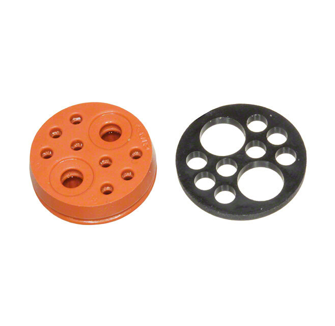
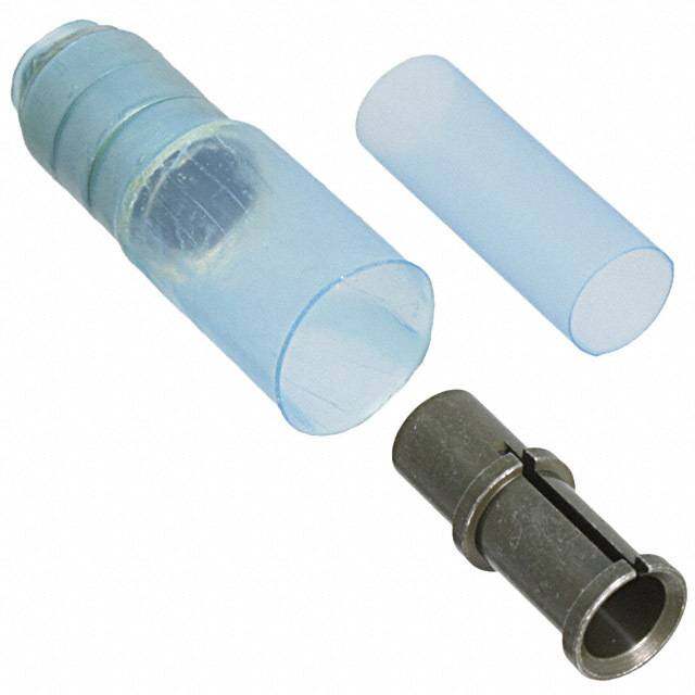
| 描述 | KEYING SIGNAL PIN CONTACT |
| 产品分类 | |
| 品牌 | ITT Cannon, LLC |
| 数据手册 | |
| 产品图片 |
|
| 产品型号 | 192990-0000 |
| rohs | 无铅 / 符合限制有害物质指令(RoHS)规范要求 |
| 产品系列 | Trident |
| 其它名称 | 1003-1308 |
| 外壳尺寸-插件 | - |
| 材料 | - |
| 标准包装 | 1 |
| 特性 | - |
| 配件类型 | 辨别键,信号引脚 |
| 配套使用产品/相关产品 | Trident Neptune 连接器 |
| 配用 | /product-detail/zh/192923-5920/192923-5920-ND/2642891/product-detail/zh/TST24PA00/1003-1376-ND/2642892/product-detail/zh/192990-0350/192990-0350-ND/2642903/product-detail/zh/TST04PA00/TST04PA00-ND/2642904 |
| 颜色 | - |


- 商务部:美国ITC正式对集成电路等产品启动337调查
- 曝三星4nm工艺存在良率问题 高通将骁龙8 Gen1或转产台积电
- 太阳诱电将投资9.5亿元在常州建新厂生产MLCC 预计2023年完工
- 英特尔发布欧洲新工厂建设计划 深化IDM 2.0 战略
- 台积电先进制程称霸业界 有大客户加持明年业绩稳了
- 达到5530亿美元!SIA预计今年全球半导体销售额将创下新高
- 英特尔拟将自动驾驶子公司Mobileye上市 估值或超500亿美元
- 三星加码芯片和SET,合并消费电子和移动部门,撤换高东真等 CEO
- 三星电子宣布重大人事变动 还合并消费电子和移动部门
- 海关总署:前11个月进口集成电路产品价值2.52万亿元 增长14.8%


PDF Datasheet 数据手册内容提取
Trident Series
We Connect When it matters most For more than a century, ITT Cannon has developed innovative interconnect solutions for the world’s harshest environments. With facilities in the United States, Germany, Italy, Mexico, China and Japan, each with its unique strengths, we offer our customers interconnect solutions that are truly Engineered for Life. In addition to this truly global footprint, we offer highly specialized, segmented industry expertise. We have a proven track record as an industry leader in harsh-environment applications. This has equipped us with the knowledge needed to continue to produce the most resilient, reliable connectors for our customers’ most challenging conditions. Interconnect solutions for the harshest environments. Key Features • Simple to install and maintain • Hand insertable contacts • No wedge locks or blind seals required The ITT Cannon difference • From 2 way to 24-way layouts • Global capabilities & local support • Up to IP69K sealing • Proven application expertise • Utilizes Trident Contacts • A century of interconnect leadership • Positive locking latch & polarization key • A committed innovator & business partner • Excellent cost/performance ratio About ITT ITT is a diversified leading manufacturer of highly engineered critical components and customized technology solutions for the energy, transportation and industrial markets. Building on its heritage of innovation, ITT partners with its customers to deliver enduring solutions to the key industries that underpin our modern way of life. Founded in 1920, ITT is headquartered in White Plains, N.Y., with employees in more than 35 countries and sales in a total of approximately 125 countries. For more information, visit www.itt.com.
lndustrial / lnstrumentation Rail Defense Vehicles Oil & Gas Medical Commercial & Military Aerospace Our connector portfolio remains the most extensive in the industry. Heavy Equipment Offering a reliable and cost effective range of interconnect solutions. www.ittcannon.com 3
Additional interconnect solutions utilizing the trusted and proven Trident contact system ITT Cannon’s Trident T2P and T3P contact technology is an extremely reliable and effective solution for harsh environment interconnects. In addition to the extensive Trident range, this contact technology is used in a number of ITT Cannon and Veam connector series including: CTC Series This cost-effective, footprint minimized solution for harsh environment vehicle wiring applications is available in 8 to 24-way layouts. Extremely simple to install and maintain it delivers an IP69K sealing without the need for wedge locks or blind seals. APD Series This full-plastic, proven bayonet series with IP69K sealing and color and mechanical coding is an ideal solution for multiple harsh transportation and industrial environments that require high sealing grades. VRPC Series This full plastic rectangular sealed connector series for multiple transport and industrial applications is extremely durable, small and light weight and meets stringent NFF fire and smoke resistance standards for Rail. www.ittcannon.com 4
Cannon Trident Connectors Table of Contents Description Trident Connector System Cannon’s Trident Connector System is a versatile range of electrical Connector Selection Guide ........................................6 connectors based on a standard • Snap Together - Rectangular contact design. These contacts are Introduction..........................................7 fully interchangeable throughout How to Order.........................................8 the Trident Connector System. The Contact Cavity Arrangements.............................9 connector options include low cost retangulars, rack and panel, Connectors....................................... 10-13 industrial grade circulars, harsh • Flame Retardant - Rectangular environment circulars and shielded Introduction.........................................14 circulars. Contact Cavity Arrangements............................15 Connectors....................................... 16-17 • Snap Together - Slimline Introduction.........................................18 How to Order........................................19 Connectors....................................... 19-21 • Ringlock Circular Connectors Introduction.........................................22 How to Order........................................23 Contact Cavity Arrangements............................24 Connectors....................................... 25-28 Accessories....................................... 29-31 • Neptune Circular Connectors Introduction.........................................31 How to Order........................................33 Contact Cavity Arrangements............................34 Connectors....................................... 35-42 Accessories....................................... 43-47 • TNM Circular Connectors Introduction.........................................48 How to Order........................................49 Contact Cavity Arrangements............................49 Connectors....................................... 50-53 Accessories....................................... 54-56 • High Voltage Introduction.........................................57 Connectors..........................................58 • Contacts Introduction and Performance Data.......................59 Contact Selection Guide............................. 60-61 T2P............................................. 62-63 T3P............................................. 64-67 Power..............................................67 Tools................................................... 70-71 Assembly Instructions ....................................... 72-79 Reader’s Resource IP Rating Chart.................................... 81-82 Glossary of Terms.................................. 83-84 Part Number Index . . . . . . . . . . . . . . . . . . . . 85-87 Product Safety Information . . . . . . . . . . . . . . . . .88 Warranty . . . . . . . . . . . . . . . . . . . . . . . . . . . . . .88 www.ittcannon.com 5
Cannon Trident Connectors Connector Selection Guide Flame Snap Together Circular Retardant Neptune Metal High Voltage Rectangular Slimline Rectangular Ringlock Neptune (TNM) (THV) Up to 250 V ac rms Operating Up to Up to Up to Up to Up to Up to Up to 380 V ac Voltage1 250 V ac rms 250 V ac rms 250 V ac rms 250 V ac rms 250 V ac rms 500 V ac rms rms (7 position connector only) Up to 13 A Up to 13 A Up to 16 A with Up to 13 A Up to 16 A High Conductivity with High Contacts Current Up to 34 A with Up to 13 A Up to 10 A Up to 13 A Up to 16 A with Conductivity Rating2 Up to 30 A with Power Contacts High Conductivity Contacts Power Contacts Contacts Up to 30 A with Up to 40 A with Power Contacts D Sub Contacts -55°C to +105°C -55°C to +105°C -55°C to -40°C to (-67°F to +221°F) (-67°F to +221°F) Operating -55°C to +105°C -55°C to +105°C -55°C to +105°C +105°C +125°C (from -40°C, -40°F (from -40°C, -40°F Temperature (-67°F to +221°F) (-67°F to +221°F) (-67°F to +221°F) (-67°F to (-40°F to for for +221°F) +257°F) PCB versions) PCB versions) Insulation 5000 MW at 5000 MW at 5000 MWat 5000 MWat 5000 MWat 5000 MWat 5000 MWat Resistance 500 V dc 500 V dc 500 V dc 500 V dc 500 V dc 500 V dc 500 V dc Up to 500 Up to 500 Up to 500 Up to 500 Up to 500 Up to 200 Up to 200 Durability3 Mating Cycles Mating Cycles Mating Cycles Mating Cycles Mating Cycles Mating Cycles Mating Cycles Environmental - - - Up to IP65 Up to IP67 Up to IP67 Up to IP67 Sealing I2/F2 according to NFF 16-101 Flammability UL 94 V-0 UL 94 V-0 (fire & smoke stan- UL 94 V-0 UL 94 V-0 UL 94 V-0 UL 94 V-0 dards) UL 94 V-0 Insulator Black Nylon Black Nylon Gray Nylon Black Nylon Black Nylon Black Nylon Orange Nylon Coupling Nickel Plated Nickel Plated Nickel Plated Nickel Plated - - - Ring Brass Brass Brass Brass 12+0, 19+0 4+0, 8+0, 12+0, 2, 3, 4, 6, 12, 2, 3, 4, 6, 12, 4, 7, 8, 12, 19, 23, 13+2, 20+4, Layouts 3, 4, 6, 9, 10 3+3, 4+3, 0+4, 4 24, 36 24, 36 28, 35, 48 28+4, 48+0, 19+0 ** 19+12 ** Page 7-13 18-21 14-17 22-31 32-47 48-56 57-58 * For details please consult the factory ** Signal + Power contacts 1 Depends on contacts used, layout, and degree of pollution 2 Depends on number and type of contacts used 3 Depends on plating and type of contacts used www.ittcannon.com 6
Cannon Trident Connectors Snap Together - Rectangular These are low installed cost connectors rated for up to 13 A and 250 V ac. They are typically used for cir- cuit board and internal wiring applications. Snap Together connectors facilitate easy assembly and remov- al of equipment such as motors, fans, transformers, etc. All Snap Together - Rectangular connectors are RoHS Compliant. Applications: • Vehicle Dashboards. • Circuit board connections. • Internal connections. Product Features • Easy cost effective installation. • Integrally molded latches and connector polarization. • Recognized under the component program of UL Inc. • Inter-connector discrimination facilities available. • Accepts formed (stamped) or machined contacts, see page 64. Performance Specifications Materials and Finishes Operating Voltage1 Up to 250 V ac rms Insulator Black Nylon, UL 94 V-0 Contact Current Rating2 Up to 13 A Operating Temperature -55°C to +105°C (-67°F to +221°F) for free Plug and Receptacles -40°C to +105°C (-40°F to +221°F) for PCB Mounted Receptacles Insulation Resistance 5000MW min. at 500 V dc Durability3 Up to 500 Mating Cylces Connector Latching Force 150 N min. with latches engaged Panel Retention Force 500 N min. Flammability UL 94 V-O 1 Depends on contacts used, layout, and degree of pollution 2 Depends on number and type of contacts used 3 Depends on plating and type of contacts used Dimensions shown in mm (inch) Specifications and dimensions subject to change www.ittcannon.com 7
Cannon Trident Connectors Snap Together - Rectangular How to Order Typical Nomenclature: TST 02 P A 0 0 * Series TST = Trident Snap Together Plating Style T = Tin Y = Gold Z = Gold Flash Number of Contacts * = None (no contacts) 02 03 04 06 12 Contact Type 0 = No Contacts (Standard for Plug and Panel 24 Mounted Receptacle) 36 1 = Machined Solder Tail Pin 2 = Machined Solder Tail Socket 5 = Formed Stamped Solder Tail Pin 6 = Formed Stamped Solder Tail Socket Color of Moulding 0 = Black Type PA Plug; Free RB Receptacle; For PCB, with Mounting Lugs Receptacle; Panel Mounting RA (delivered without any contacts) Receptacle, For PCB, 90° Right Angle Mounting RR (only for 12 position connectors with machined contacts) AS Accessory; Receptacle Shroud AH Accessory; Plug Strain Relief Hood Test Specifications The table below summarizes the results of key tests. Data is applicable to standard connectors with standard contacts. Variations may affect this data, so please consult factory for further information on your requirements. Test Method Criteria of Acceptance Dielectric Withstanding Voltage 2000 V ac No breakdown Thermal Shock -55°C to +125°C (-67°F to +257°F), 5 cycles No physical damage Physical Shock 50 g’s peak, 3 axes, No physical damage. 11 millisecond duration half-sine pulse No loss of continuity >1 sec Vibration 10 g’s peak, No physical damage, 10-500 Hz, 9 hours No loss of continuity >1 sec Durability 500 cycles of mating and unmating, No mechanical or 500 mating cycles max electrical defects Salt Spray 48 hours Shall be capable of mating and unmating and meet contact resistance requirements High Temperature Endurance 1000 hours at 125°C (+257°F) Insulation Resistance > 100 MΩ Humidy Steady State RH 90-95%, 40°C (+104°F), 504 hours Insulation Resistance > 100 MΩ Moisture Resistance 10 Cycles Insulation Resistance > 100 MΩ Dimensions shown in mm (inch) Specifications and dimensions subject to change www.ittcannon.com 8
Cannon Trident Connectors Snap Together - Rectangular Contact Cavity Arrangements — Mating Face View 2-way 3-way 4-way Plug Receptacle Plug Receptacle Plug Receptacle 6-way 12-way Plug Receptacle Plug Receptacle 24-way Plug Receptacle 36-way Plug Receptacle Dimensions shown in mm (inch) Specifications and dimensions subject to change www.ittcannon.com 9
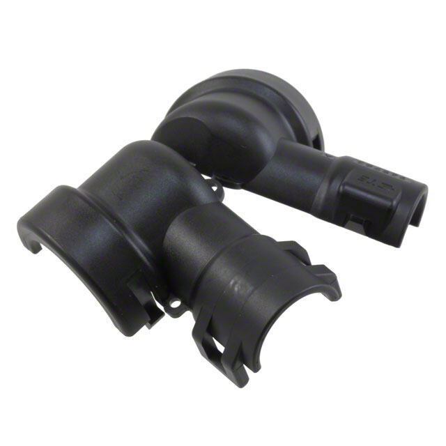
Cannon Trident Connectors Snap Together - Rectangular Free Plug Number of Pack of 100 Dimensions (max.) Contacts Part Number Nomenclature A B • Accepts Pin or Socket contacts. 2 192990-0350 TST02PA00 15,50 (.610) 17,00 (.669) 3 192923-5920 TST03PA00 19,00 (.748) 17,00 (.669) • Contacts to be ordered separately, see page 64. 4 192990-0370 TST04PA00 24,00 (.944) 17,00 (.669) • Mates with panel mounted receptacles, 6 192923-5930 TST06PA00 19,00 (.748) 22,00 (.866) see page 11. 12 192923-5940 TST12PA00 19,00 (.748) 32,00 (1.259) 24 192923-5950 TST24PA00 24,00 (.944) 42,00 (1.653) • Mates with PCB mounted receptacles, 36 192923-5960 TST36PA00 49,50 (1.948) 32,00 (1.259) see pages 12-13. • Connector Discriminating (Keying) Pins available, see page 69. Accessory — Plug Strain Relief Hood • Provides strain relief and wire protection. • Secure with a tie-wrap (customer supplies tie-wrap). Pack of 100 Number of Dimensions (max.) Contacts Part Number Nomenclature Wire Bundle Dia. A B C D 2 192990-0460 TST02AH00 2,30-8,30 (.090-.326) 46,20 (1.818) 16,10 (.633) 11,00 (.433) 56,50 (2.224) 3 192990-0470 TST03AH00 2,30-8,30 (.090-.326) 46,20 (1.818) 18,60 (.732) 11,00 (.433) 56,50 (2.224) 4 192990-0480 TST04AH00 3,00-10,00 (.118-.393) 46,20 (1.818) 23,70 (.933) 11,00 (.433) 56,50 (2.224) 6 192923-5970 TST06AH00 2,30-8,30 (.090-.326) 46,20 (1.818) 19,00 (.748) 16,40 (.645) 56,50 (2.224) 12 192923-5980 TST12AH00 3,00-10,00 (.118-.393) 45,50 (1.791) 19,00 (.748) 26,40 (1.039) 55,80 (2.196) 24 192923-5990 TST24AH00 4,60-12,70 (.181-.500) 51,00 (2.007) 24,10 (.948) 36,80 (1.448) 60,30 (2.374) 36 192923-6000 TST36AH00 7,00-15,90 (.275-.625) 57,50 (2.263) 49,50 (1.948) 26,40 (1.039) 68,00 (2.677) Dimensions shown in mm (inch) Specifications and dimensions subject to change www.ittcannon.com 10
Cannon Trident Connectors Snap Together - Rectangular Panel Cutout Receptacle — Panel Mounted • Accepts Pin or Socket contacts. • Contacts to be ordered separately, see page 60. • Mates with Free Plugs, see page 10. • Connector Discriminating (Keying) Pins available, see page 69. Pack of 100 Dimensions Number of C D Contacts Part Number Nomenclature A B ±0,13 (.005) ±0,13 (.005) 2 192990-0360 TST02RA00 19,00 (.748) 14,00 (.551) 11,50 (.452) 11,60 (.456) 3 192923-6010 TST03RA00 24,00 (.944) 14,00 (.551) 16,50 (.649) 11,60 (.456) 4 192990-0380 TST04RA00 29,00 (1.141) 14,00 (.551) 21,70 (.854) 11,60 (.456) 6 192923-6020 TST06RA00 24,00 (.944) 19,00 (.748) 16,50 (.649) 16,70 (.657) 12 192923-6030 TST12RA00 24,00 (.944) 29,00 (1.141) 16,70 (.657) 26,70 (1.051) 24 192923-6040 TST24RA00 29,00 (1.141) 39,00 (1.535) 21,80 (.858) 36,90 (1.452) 36 192923-6050 TST36RA00 54,20 (2.133) 29,00 (1.141) 46,70 (1.838) 26,40 (1.039) Section X-X Accessory — Pack of 100 Dimensions Protection Shrouds Number of Contacts Part Number Nomenclature A B for Receptacles with 3 192990-0400 TST03AS00 23,50 (.925) 19,05 (.748) Pin Contacts 4 192991-0668 TST04AS00 28,60 (1.126) 19,05 (.748) 6 192990-0420 TST06AS00 23,50 (.925) 24,13 (.948) • Provides protection for panel mounted 12 192990-0430 TST12AS00 23,60 (.929) 34,20 (1.346) receptacles with pin contacts. 24 192990-0440 TST24AS00 29,70 (1.169) 44,40 (1.748) 36 192990-0450 TST36AS00 54,40 (2.141) 34,00 (1.338) • Shrouds can be fitted onto panels up to 1,40 (.055) thick. Dimensions shown in mm (inch) Specifications and dimensions subject to change www.ittcannon.com 11
Cannon Trident Connectors Snap Together - Rectangular Figure 1 Receptacle — Figure 2 PCB Mounted with Pin Contacts • Mates with Free Plug, see page 10. • Integrally molded flanges. • Contacts are on a 5,08 (.200) grid, symmetrical on center lines. • Recommended PCB hole Ø1,15 (.045). • Connector Discriminating Caps available, see page 69. Pack of 100 Formed (Stamped) Machined Dimensions Number of B C Contacts Plating Part Number Nomenclature Part Number Nomenclature Figure A ±0,08 (.003) ±0,08 (.003) D E 2 Gold* 192900-0411 TST02RB05Y 192991-0270 TST02RB01Z 1 11,13 (.438) N/A 19,13 (.753) 6,00 (.236) 25,00 (.984) 2 Tin 192990-3230 TST02RB05T 192991-0271 TST02RB01T 1 11,13 (.438) N/A 19,13 (.753) 6,00 (.236) 25,00 (.984) 3 Gold* 192900-0412 TST03RB05Y 192991-0278 TST03RB01Z 2 16,21 (.638) 14,05 (.553) 10,24 (.403) 6,00 (.236) 20,10 (.791) 3 Tin 192990-3240 TST03RB05T 192991-0279 TST03RB01T 2 16,21 (.638) 14,05 (.553) 10,24 (.403) 6,00 (.236) 20,10 (.791) 4 Gold* 192900-0413 TST04RB05Y 192991-0286 TST04RB01Z 2 21,30 (.838) 14,05 (.553) 15,32 (.603) 6,00 (.236) 20,10 (.791) 4 Tin 192990-3250 TST04RB05T 192991-0287 TST04RB01T 2 21,30 (.838) 14,05 (.553) 15,32 (.603) 6,00 (.236) 20,10 (.791) 6 Gold* 192900-0414 TST06RB05Y 192991-0294 TST06RB01Z 2 16,20 (.637) 19,12 (.752) 10,23 (.402) 11,00 (.433) 26,00 (1.023) 6 Tin 192990-3260 TST06RB05T 192991-0295 TST06RB01T 2 16,20 (.637) 19,12 (.752) 10,23 (.402) 11,00 (.433) 26,00 (1.023) 12 Gold* 192900-0415 TST12RB05Y 192991-0302 TST12RB01Z 2 16,20 (.637) 29,30 (1.153) 10,26 (.404) 21,20 (.834) 35,20 (1.385) 12 Tin 192990-3270 TST12RB05T 192991-0303 TST12RB01T 2 16,20 (.637) 29,30 (1.153) 10,26 (.404) 21,20 (.834) 35,20 (1.385) 24 Gold* 192900-0416 TST24RB05Y 192991-0310 TST24RB01Z 2 21,30 (.838) 39,37 (1.550) 15,32 (.603) 31,30 (1.232) 45,60 (1.795) 24 Tin 192990-3280 TST24RB05T 192991-0311 TST24RB01T 2 21,30 (.838) 39,37 (1.550) 15,32 (.603) 31,30 (1.232) 45,60 (1.795) 36 Gold* 192900-0417 TST36RB05Y 192991-0402 TST36RB01Z 1 46,60 (1.834) 15,24 (.600) 54,64 (2.151) 21,20 (.834) 60,50 (2.382) 36 Tin 192990-3290 TST36RB05T 192991-0403 TST36RB01T 1 46,60 (1.834) 15,24 (.600) 54,64 (2.151) 21,20 (.834) 60,50 (2.382) * Gold plating for Formed (Stamped) Contacts is 0,75 µm (30 µ in.) min gold. Gold plating for Machined Contacts is gold flash. Dimensions shown in mm (inch) Specifications and dimensions subject to change www.ittcannon.com 12
Cannon Trident Connectors Snap Together - Rectangular Figure 1 Receptacle — Figure 2 PCB Mounted with Socket Contacts • Mates with Free Plug, see page 10. • Integrally molded flanges. • Contacts are on a 5,08 (.200) grid, symmetrical on center lines. • Recommended PCB hole Ø 1,15 (.045). • Connector Discriminating Pegs available, see page 69. Pack of 100 Formed (Stamped) Machined Dimensions Number of B C Contacts Plating Part Number Nomenclature Part Number Nomenclature Figure A ±0,08 (.003) ±0,08 (.003) D E 2 Gold* 192900-0418 TST02RB06Y 192991-0213 TST02RB02Z 1 11,13 (.438) N/A 19,13 (.753) 6,00 (.236) 25,00 (.984) 2 Tin 192990-3300 TST02RB06T 192991-0214 TST02RB02T 1 11,13 (.438) N/A 19,13 (.753) 6,00 (.236) 25,00 (.984) 3 Gold* 192900-0419 TST03RB06Y 192991-0221 TST03RB02Z 2 16,21 (.638) 14,05 (.553) 10,24 (.403) 6,00 (.236) 20,10 (.791) 3 Tin 192990-3310 TST03RB06T 192991-0222 TST03RB02T 2 16,21 (.638) 14,05 (.553) 10,24 (.403) 6,00 (.236) 20,10 (.791) 4 Gold* 192900-0420 TST04RB06Y 192991-0229 TST04RB02Z 2 21,30 (.838) 14,05 (.553) 15,32 (.603) 6,00 (.236) 20,10 (.791) 4 Tin 192990-3320 TST04RB06T 192991-0230 TST04RB02T 2 21,30 (.838) 14,05 (.553) 15,32 (.603) 6,00 (.236) 20,10 (.791) 6 Gold* 192900-0421 TST06RB06Y 192991-0237 TST06RB02Z 2 16,20 (.637) 19,12 (.752) 10,23 (.402) 11,00 (.433) 26,00 (1.023) 6 Tin 192990-3330 TST06RB06T 192991-0238 TST06RB02T 2 16,20 (.637) 19,12 (.752) 10,23 (.402) 11,00 (.433) 26,00 (1.023) 12 Gold* 192900-0422 TST12RB06Y 192991-0245 TST12RB02Z 2 16,20 (.637) 29,30 (1.153) 10,26 (.404) 21,20 (.834) 35,20 (1.385) 12 Tin 192990-3340 TST12RB06T 192991-0246 TST12RB02T 2 16,20 (.637) 29,30 (1.153) 10,26 (.404) 21,20 (.834) 35,20 (1.385) 24 Gold* 192900-0423 TST24RB06Y 192991-0253 TST24RB02Z 2 21,30 (.838) 39,37 (1.550) 15,32 (.603) 31,30 (1.232) 45,60 (1.795) 24 Tin 192990-3350 TST24RB06T 192991-0254 TST24RB02T 2 21,30 (.838) 39,37 (1.550) 15,32 (.603) 31,30 (1.232) 45,60 (1.795) 36 Gold* 192900-0424 TST36RB06Y 192991-0261 TST36RB02Z 1 46,60 (1.834) 15,24 (.600) 54,64 (2.151) 21,20 (.834) 60,50 (2.382) 36 Tin 192990-3360 TST36RB06T 192991-0262 TST36RB02T 1 46,60 (1.834) 15,24 (.600) 54,64 (2.151) 21,20 (.834) 60,50 (2.382) * Gold plating for Formed (Stamped) Contacts is 0,75 µm (30 µ in.) min gold. Gold plating for Machined Contacts is gold flash. Dimensions shown in mm (inch) Specifications and dimensions subject to change www.ittcannon.com 13
Cannon Trident Connectors Flame Retardant - Rectangular This connector series is compliant to railway standards. The material properties are I2/F2 according to NFF 16-101 & NFF 16-102. These are low installed cost connectors rated for up to 13 A and 250 V ac. They are typically used for circuit board and internal wiring applications. All flame retardant connectors are RoHS Compliant. Applications: • Vehicle Dashboards. • Circuit board connections. • Internal connections. • Railway. • Lighting. • Cabin Applications. • Control Consoles. Product Features • Material properties I2/F2 according to NFF 16-101 & NFF 16-102 • Easy cost effective installation. • Integrally molded latches and connector polarization. • Accepts formed (stamped) or machined contacts, see page 64. Performance Specifications Materials and Finishes Insulator Gray Nylon Operating Voltage1 Up to 250 V ac rms Contact Current Rating2 Up to 13 A Operating Temperature -55°C to +105°C (-67°F to +221°F) for free Plug and Receptacles Insulation Resistance 5000MW min. at 500 V dc Durability3 Up to 500 Mating Cylces Connector Latching Force 150 N min. with latches engaged Panel Retention Force 500 N min. Flammability UL 94 V-0 1 Depends on contacts used, layout, and degree of pollution 2 Depends on number and type of contacts used 3 Depends on plating and type of contacts used Dimensions shown in mm (inch) Specifications and dimensions subject to change www.ittcannon.com 14
Cannon Trident Connectors Flame Retardant - Rectangular Contact Cavity Arrangements — Mating Face View 2-way 3-way 4-way 6-way 12-way Plug Receptacle Plug Receptacle 24-way Plug Receptacle 36-way Plug Receptacle Dimensions shown in mm (inch) Specifications and dimensions subject to change www.ittcannon.com 15
Cannon Trident Connectors Flame Retardant - Rectangular Free Plug Pack of 100 Number of Dimensions (max.) Contacts Part Number Nomenclature A B • Accepts Pin or Socket contacts. 2 121587-0010 TFR02PA10 15,50 (.610) 17,00 (.669) 3 121587-0011 TFR03PA10 19,00 (.748) 17,00 (.669) • Contacts to be ordered separately, 4 121587-0012 TFR04PA10 24,00 (.944) 17,00 (.669) see page 60. 6 121587-0013 TFR06PA10 19,00 (.748) 22,00 (.866) • Mates with panel mounted receptacles, 12 121587-0014 TFR12PA10 19,00 (.748) 32,00 (1.259) see page 17. 24 121587-0015 TFR24PA10 24,00 (.944) 42,00 (1.653) • Connector Discriminating (Keying) Pins 36 121587-0016 TFR36PA10 49,50 (1.948) 32,00 (1.259) available, see page 68. Accessory — Plug Strain Relief Hood • Provides strain relief and wire protection. • Secure with a tie-wrap (customer supplies tie-wrap). Pack of 100 Number of Dimensions (max.) Contacts Part Number Nomenclature Wire Bundle Dia. A B C D 2 121587-0020 TFR02AH10 2,30-8,30 (.090-.326) 46,20 (1.818) 16,10 (.633) 11,00 (.433) 56,50 (2.224) 3 121587-0021 TFR03AH10 2,30-8,30 (.090-.326) 46,20 (1.818) 18,60 (.732) 11,00 (.433) 56,50 (2.224) 4 121587-0022 TFR04AH10 3,00-10,00 (.118-.393) 46,20 (1.818) 23,70 (.933) 11,00 (.433) 56,50 (2.224) 6 121587-0023 TFR06AH10 2,30-8,30 (.090-.326) 46,20 (1.818) 19,00 (.748) 16,40 (.645) 56,50 (2.224) 12 121587-0024 TFR12AH10 3,00-10,00 (.118-.393) 45,50 (1.791) 19,00 (.748) 26,40 (1.039) 55,80 (2.196) 24 121587-0025 TFR24AH10 4,60-12,70 (.181-.500) 51,00 (2.007) 24,10 (.948) 36,80 (1.448) 60,30 (2.374) 36 121587-0026 TFR36AH10 7,00-15,90 (.275-.625) 57,50 (2.263) 49,50 (1.948) 26,40 (1.039) 68,00 (2.677) Dimensions shown in mm (inch) Specifications and dimensions subject to change www.ittcannon.com 16
Cannon Trident Connectors Flame Retardant - Rectangular Kit — Pack of 100 Number of Plug and Strain Relief Hood Contacts Part Number Nomenclature 2 121587-0040 TFR02PH10 • Provides protection for panel mounted 3 121587-0041 TFR03PH10 receptacles with pin contacts. 4 121587-0042 TFR04PH10 6 121587-0043 TFR06PH10 • Shrouds can be fitted onto panels up to 1,40 (.055) thick. 12 121587-0044 TFR12PH10 24 121587-0045 TFR24PH10 36 121587-0046 TFR36PH10 Panel Cutout Receptacle — Panel Mounted • Accepts Pin or Socket contacts. • Contacts to be ordered separately, see page 60. • Mates with Free Plugs, see page 16. • Connector Discriminating (Keying) Pins available, see page 68. Pack of 100 Dimensions Number of C D Contacts Part Number Nomenclature A B ±0,13 (.005) ±0,13 (.005) 2 121587-0030 TFR02RA10 19,00 (.748) 14,00 (.551) 11,50 (.452) 11,60 (.456) 3 121587-0031 TFR03RA10 24,00 (.944) 14,00 (.551) 16,50 (.649) 11,60 (.456) 4 121587-0032 TFR04RA10 29,00 (1.141) 14,00 (.551) 21,70 (.854) 11,60 (.456) 6 121587-0033 TFR06RA10 24,00 (.944) 19,00 (.748) 16,50 (.649) 16,70 (.657) 12 121587-0034 TFR12RA10 24,00 (.944) 29,00 (1.141) 16,70 (.657) 26,70 (1.051) 24 121587-0035 TFR24RA10 29,00 (1.141) 39,00 (1.535) 21,80 (.858) 36,90 (1.452) 36 121587-0036 TFR36RA10 54,20 (2.133) 29,00 (1.141) 46,70 (1.838) 26,40 (1.039) Dimensions shown in mm (inch) Specifications and dimensions subject to change www.ittcannon.com 17
Cannon Trident Connectors Snap Together - Slimline The Slimline offers a low profile connector system that is well suited for circuit board applications. The precision machined contacts are ideal for power and sensitive signals. All Snap Together - Slimline connectors are RoHS Compliant. Applications: • Junction Boxes. • Communications equipment. • Test equipment. • Instrumentation. Product Features • Less than 10,00 (.393) width on PC board. • Pin headers pre-loaded with straight or 90° machined solder tail pins. • Mating plug accepts all Trident signal crimp socket contacts, see page 60. • Plugs have integrally molded quick connect/disconnect latches. • Five single row contact arrangements available. • Recognized under the component program of UL Inc. • Gold plated version available with earth pin capability. • 10 A per circuit. Performance Specifications Materials and Finishes Operating Voltage1 Up to 250 V ac rms Insulator Black Nylon, UL 94 V-0 Contact Current Rating2 Up to 10 A Operating Temperature -55°C to +105°C (-67°F to +221°F) for free Plug & Receptacles -40°C to +105°C (-40°F to +221°F) for PCB Mounted Receptacles Insulation Resistance 5000MW min. at 500 V dc Durability3 Up to 500 Mating Cylces Connector Latching Force 150 N min. with latches engaged 1 Depends on contacts used, layout, and degree of pollution Panel Retention Force 500 N min. 2 Depends on number and type of contacts used 3 Depends on plating and type of contacts used Flammability UL 94 V-0 Test Specifications The table below summarizes the results of key tests. Data is applicable to standard connectors with standard contacts. Variations may affect this data, so please consult factory for further information on your requirements. Test Method Criteria of Acceptance Dielectric Withstanding Voltage 2000 V ac No breakdown Thermal Shock -55°C to +125°C (-67°F to +257°F), 5 cycles No physical damage Physical Shock 50 g’s peak, 3 axes, No physical damage. 11 millisecond duration half-sine pulse No loss of continuity >1 sec Vibration 10 g’s peak, No physical damage, 10-500 Hz, 9 hours No loss of continuity >1 sec Durability 500 cycles of mating and unmating, No mechanical or 500 mating cycles max electrical defects Salt Spray 48 hours Shall be capable of mating and unmating and meet contact resistance requirements High Temperature Endurance 1000 hours at 125°C (+257°F) Insulation Resistance > 100 MΩ Humidy Steady State RH 90-95%, 40°C (+125°F), 504 hours Insulation Resistance > 100 MΩ Moisture Resistance 10 Cycles Insulation Resistance > 100 MΩ Dimensions shown in mm (inch) Specifications and dimensions subject to change www.ittcannon.com 18
Cannon Trident Connectors Snap Together - Slimline How to Order Typical Nomenclature: TST 03 P F 0 0 * Series Plating Style * = None (Plug only) T = Tin TST = Trident Snap Together Y = 0,4 mm Gold overall Number of Contacts Contact Type 0 = No Contacts (Standard for Plug and Panel 03 04 Mounted Receptacle) 06 1 = Machined Solder Tail Pin 09 2 = Machined Solder Tail Socket 10 5 = Formed Stamped Solder Tail Pin 6 = Formed Stamped Solder Tail Socket Color of Moulding 0 = Black Variant RD PCB Receptacle; Straight Contacts Materials and Finishes RE PCB Receptacle; 90° Contacts PF Plug Plug Connector • Socket contacts must be ordered separately for the plug connectors, see page 60. Pack of 100 Number of D Contacts Part Number Nomenclature max. 3 192990-0960* TST03PF00 16,10 (.633) 4 192990-0970 TST04PF00 21,20 (.834) 6 192990-0980 TST06PF00 31,40 (1.236) 9 192990-0990 TST09PF00 46,60 (1.834) 10 192990-1000 TST10PF00 51,60 (2.031) *Available in gray (material properties I2/F2 according to NFF 16-101 & NFF 16-102), part number: 192990-0965. Dimensions shown in mm (inch) Specifications and dimensions subject to change www.ittcannon.com 19
Cannon Trident Connectors Snap Together - Slimline Receptacle with Straight Pin Contacts • For gold plated versions extended earth pins are available in any one or two positions. Contact your local Cannon Sales Office for further details. Pack of 100 Gold Plated Version 0,4µm (16µin.) min. Gold Tin Plated Version Dimensions (max.) Number of Contacts Part Number Nomenclature Part Number Nomenclature A B C 3 192991-0337 TST03RD01Y 192991-0316 TST03RD01T 31,40 (1.236) 19,40 (.763) 25,50 (1.003) 4 192991-0347 TST04RD01Y 192991-0318 TST04RD01T 36,50 (1.437) 14,50 (.964) 30,60 (1.204) 6 192991-0342 TST06RD01Y 192991-0320 TST06RD01T 46,70 (1.838) 34,70 (1.366) 40,70 (1.602) 9 192991-0536 TST09RD01Y 192991-0322 TST09RD01T 61,90 (2.437) 49,90 (1.964) 56,00 (2.204) 10 192991-0354 TST10RD01Y 192991-0324 TST10RD01T 67,00 (2.637) 55,00 (2.165) 61,10 (2.405) PCB Layout Number of D Contacts max. 3 25,50 (1.003) 4 30,60 (1.204) 6 40,70 (1.602) 9 56,00 (2.204) 10 61,10 (2.405) Dimensions shown in mm (inch) Specifications and dimensions subject to change www.ittcannon.com 20
Cannon Trident Connectors Snap Together - Slimline Receptacle with 90° Pin Contacts • For gold plated versions extended earth pins are available in any one or two positions. Contact your local Cannon Sales Office for further details. Pack of 100 Gold Plated Version 0,4µm (16µin.) min. Gold Tin Plated Version Dimensions (max.) Number of Contacts Part Number Nomenclature Part Number Nomenclature A B C 3 192991-0532* TST03RE01Y 192991-0317 TST03RE01T 31,40 (1.236) 19,40 (.763) 25,50 (1.003) 4 192991-0533 TST04RE01Y 192991-0319 TST04RE01T 36,50 (1.437) 14,50 (.964) 30,60 (1.204) 6 192991-0534 TST06RE01Y 192991-0321 TST06RE01T 46,70 (1.838) 34,70 (1.366) 40,70 (1.602) 9 192991-0535 TST09RE01Y 192991-0323 TST09RE01T 61,90 (2.437) 49,90 (1.964) 56,00 (2.204) 10 192991-0538 TST10RE01Y 192991-0325 TST10RE01T 67,00 (2.637) 55,00 (2.165) 61,10 (2.405) *Available in gray (material properties I2/F2 according to NFF 16-101 & NFF 16-102), part number: 192991-0539. PCB Layout Number of D Contacts max. 3 25,50 (1.003) 4 30,60 (1.204) 6 40,70 (1.602) 9 56,00 (2.204) 10 61,10 (2.405) Dimensions shown in mm (inch) Specifications and dimensions subject to change www.ittcannon.com 21
Cannon Trident Connectors Ringlock Circular Connectors Ringlock is a range of robust circular connectors for industrial and transportation applications. It uses a metal bayonet coupling system for quick and reliable connections and thermoplastic bodies for low installed cost. The connectors are available in several sizes ranging from 4 to 48 circuits for signals of up to 16 A. With the addition of a cable clamp, the connectors can be water sealed to meet IP65. All Ringlock Circular Connectors are RoHS Compliant. Applications: Product Features • Industrial Electronics. • Rugged metal coupling. • Wide range of accessories. • Robotic Systems. • Available in unsealed and • Accepts all Trident signal sealed versions. contacts. • Manufacturing Equipment. • Positive bayonet locking. • PCB versions are available. • Printing Equipment. • Instrumentation. • Shell to shell keying. • Recognized under the component program of UL Inc. • Machine Building. • Integrally molded combined plastic body and insulator. Performance Specifications Materials and Finishes - Operating Voltage1 Up to 250 V ac rms Connector Body Black Nylon Up to 380 V ac rms (Size 1807 only) Coupling Ring Nickel Plated Copper Alloy Contact Current Rating2 Up to 13 A, Up to 16 A with High Conductivity Contacts Bayonet Pins Stainless Steel Bayonet Pins Support Band Nickel Plated Copper Alloy Operating Temperature -55°C to +105°C (-67°F to + 221°F) Insulation Resistance 5000MW min. at 500 V dc Durability3 Up to 500 Mating Cycles Environmental Sealing Up to IP65 Flammability UL 94 V-0 1 Depends on contacts used, layout and degree of pollution 2 Depends on number and type of contacts used 3 Depends on plating and type of contact used Dimensions shown in mm (inch) Specifications and dimensions subject to change www.ittcannon.com 22
Cannon Trident Connectors Ringlock Circular Connectors Test Specifications The table below summarizes the results of key tests. Data is applicable to standard connectors with standard contacts. Variations may affect this data, so please consult factory for further information on your requirements. Test Method Criteria of Acceptance Dielectric Withstanding Voltage 1550 V ac for 60 seconds No breakdown 2500 V ac for 60 seconds (Size 1807 only) No breakdown Thermal Shock -55°C to +125°C (-67°F to +257°F), 5 cycles No physical damage. Physical Shock 50 g’s peak, 3 axes, No physical damage. 11 millisecond duration half-sine pulse No loss of continuity >1 sec Vibration 10 g’s peak,10-500 Hz, 9 hours No physical damage. No loss of continuity >1 sec Durability 500 cycles of mating and unmating, No mechanical or 500 mating cycles max Electrical defects Salt Spray 48 hours Shall be capable of mating and unmating and meet contact resistance requirements High Temperature Endurance 1000 hours at 125°C (+257°F) Insulation Resistance > 100 MΩ Humidy Steady State RH 90-95%, 40°C(+104°F), 504 hours Insulation Resistance > 100 MΩ Moisture Resistance 10 Cycles Insulation Resistance > 100 MΩ How to Order-Connectors Typical Nomenclature: TR 16 19 P M S 1 N B Series TR = Trident Ringlock Color Shell Number of B = Black Size Contacts 10 04 Material 12 08 N = Nylon 14 12 16 19 Series Identification 18 07 1 = Standard 18 23 20 28 S = Standard 22 35 H = Interface Sealing* 24 48 P = Plastic Coupling Nut** M = Accepts Male Contacts F = Accepts Female Contacts * Receptacle only ** Shell size 16 and 24 only P = Plug R = Receptacle Dimensions shown in mm (inch) Specifications and dimensions subject to change www.ittcannon.com 23
Cannon Trident Connectors Ringlock Circular Connectors Contact Cavity Arrangements Mating Face View, Standard Plug (Mating Face View, Reversed Plug is mirror image) Shell Size Number of Contacts Shell Size 10 Shell Size 12 Shell Size 14 4 8 12 Shell Size 16 Shell Size 18 Shell Size 18 19 7 (VDE 0110)* 23 Shell Size 20 Shell Size 22 Shell Size 24 28 35 48 * Meets creepage and clearance requirements according to VDE 0110. Note: The shell size indicates the diameter of the interface in sixteenths of an inch. Example: Shell size 16 is 1.00 inch in diameter, 25,4 mm. Dimensions shown in mm (inch) Specifications and dimensions subject to change www.ittcannon.com 24
Cannon Trident Connectors Ringlock Circular Connectors Standard Plug for Pin Contacts • Mates with Standard Receptacles, see page 26. • Accepts pin contacts, see page 60. • Discriminating (Keying) Pins available, see page 68. • Can be water sealed to IP65. Shell Number of Sing le Piece Connector Dimensions Accessory Size Contacts Part Number Nomenclature ØA ± 0,20 (.008) B max. ØC ± 0,15 (.005) ØD ± 0,15 (.005) E Thread 10 4 192922-1250 TR1004PMS1NB 21,60 (.850) 31,80 (1.252) 10,90 (.429) 12,20 (.480) 19,10 ±0,20 (.751 ±.007) 9/16 - 24 UNEF 12 8 192922-1260 TR1208PMS1NB 24,80 (.976) 31,80 (1.252) 13,80 (.543) 15,10 (.594) 19,10 ±0,20 (.751 ±.007) 11/16 - 24 UNEF 14 12 192922-1270 TR1412PMS1NB 28,00 (1.102) 31,80 (1.252) 17,00 (.669) 18,30 (.720) 19,10 ±0,20 (.751 ±.007) 13/16 - 20 UNEF 16 19 192922-1280 TR1619PMS1NB 31,20 (1.228) 31,80 (1.252) 19,90 (.783) 21,40 (.842) 19,10 ±0,20 (.751 ±.007) 15/16 - 20 UNEF 18 7 192990-1330 TR1807PMS1NB 34,30 (1.350) 33,00 (1.299) 22,50 (.885) 24,00 (.944) 19,10 ±0,20 (.751 ±.007) 1-1/16 - 18 UNEF 18 23 192990-1320 TR1823PMS1NB 34,30 (1.350) 31,80 (1.252) 22,40 (.881) 24,00 (.944) 19,10 ±0,20 (.751 ±.007) 1-1/16 - 18 UNEF 20 28 192922-1290 TR2028PMS1NB 37,50 (1.476) 31,80 (1.252) 25,60 (1.007) 27,10 (1.066) 19,10 ±0,20 (.751 ±.007) 1-3/16 - 18 UNEF 22 35 192922-1300 TR2235PMS1NB 40,70 (1.602) 31,80 (1.252) 28,50 (1.122) 30,40 (1.196) 19,10 ±0,20 (.751 ±.007) 1-5/16 - 18 UNEF 24 48 192990-1340 TR2448PMS1NB 43,90 (1.728) 31,80 (1.252) 31,70 (1.248) 33,50 (1.318) 14,72 ±0,15 (.580 ±.006) 1-7/16 - 18 UNEF Note: For versions with plastic locking ring, please consult the factory. IMPORTANT NOTE: Standard and Reversed Format Equipment design dictates whether the fixed connector is “live” or “dead” when disconnected. Connector housings are available that provide socket contacts on the live side of the equipment. Standard Format: Receptacle with socket contacts. Reversed Format: Receptacle with pin contacts. Standard and Reversed connectors are not intermateable. Dimensions shown in mm (inch) Specifications and dimensions subject to change www.ittcannon.com 25
Cannon Trident Connectors Ringlock Circular Connectors Standard Receptacle ØJ=Flange in Front of Panel for Socket Contacts ØH= Flange at Rear of Panel • Mates with Standard Plugs, see page 25. • Accepts socket contacts, see page 60. • Printed circuit contacts are available, see page 60. Dimensions Shell Number of A B C ØD E F ØG ØH ØJ Accessory Size Contacts max. ± 0,15 (.005) ± 0,20 (.007) ± 0,15 (.005) ± 0,15 (.005) ± 0,25 (.009) ± 0,10 (.003) ± 0,10 (.003) ± 0,10 (.003) Thread 10 4 24,00 (.945) 2,30 (.091) 11,15 (.439) 15,00 (.591) 18,00 (.709) 23,50 (.925) 3,25 (.128) 17,30 (.681) 15,10 (.594) 9/16 - 24 UNEF 12 8 25,80 (1.016) 2,30 (.091) 11,35 (.447) 19,00 (.748) 20,50 (.807) 26,20 (1.031) 3,25 (.128) 21,80 (.858) 18,20 (.716) 11/16 - 24 UNEF 14 12 24,00 (.945) 2,30 (.091) 11,35 (.447) 22,20 (.874) 22,60 (.890) 28,15 (1.108) 3,25 (.128) 25,00 (.984) 21,40 (.842) 13/16 - 20 UNEF 16 19 25,80 (1.016) 2,30 (.091) 11,35 (.447) 25,40 (1.000) 24,20 (.953) 30,50 (1.200) 3,25 (.128) 28,10 (1.106) 24,60 (.968) 15/16 - 20 UNEF 18 7 32,50 (1.280) 2,50 (.098) 18,20 (.716) 28,50 (1.122) 27,00 (1.063) 33,30 (1.311) 3,25 (.128) 31,30 (1.232) 27,80 (1.094) 1-1/16 - 18 UNEF 18 23 25,80 (1.016) 2,50 (.098) 11,35 (.447) 28,50 (1.122) 26,90 (1.059) 33,30 (1.311) 3,25 (.128) 31,30 (1.232) 27,80 (1.094) 1-1/16 - 18 UNEF 20 28 27,00 (1.063) 2,50 (.098) 14,50 (.571) 31,70 (1.248) 29,20 (1.150) 36,50 (1.437) 3,25 (.128) 34,50 (1.358) 30,90 (1.216) 1-3/16 - 18 UNEF 22 35 28,00 (1.102) 3,50 (.138) 14,50 (.571) 34,90 (1.374) 31,60 (1.244) 39,70 (1.563) 3,25 (.128) 37,70 (1.484) 34,10 (1.342) 1-5/16 - 18 UNEF 24 48 30,30 (1.193) 3,50 (.138) 15,30 (.602) 38,05 (1.498) 34,45 (1.356) 42,90 (1.689) 3,90 (.154) 40,90 (1.610) 37,30 (1.468) 1-7/16 - 18 UNEF Part Numbers-Single Piece Connector Shell Number of Unsealed Sealed (see important note below) Size Contacts Part Number Nomenclature Part Number Nomenclature 10 4 192922-1190 TR1004RFS1NB 192990-1660 TR1004RFH1NB 12 8 192922-1200 TR1208RFS1NB 192990-1670 TR1208RFH1NB 14 12 192922-1210 TR1412RFS1NB 192990-1680 TR1412RFH1NB 16 19 192922-1220 TR1619RFS1NB 192990-1690 TR1619RFH1NB 18 7 192990-1300 TR1807RFS1NB 192990-1700 TR1807RFH1NB 18 23 192990-1290 TR1823RFS1NB 192990-1710 TR1823RFH1NB 20 28 192922-1230 TR2028RFS1NB 192990-1720 TR2028RFH1NB 22 35 192922-1240 TR2235RFS1NB 192990-1730 TR2235RFH1NB 24 48 192990-1310 TR2448RFS1NB 192990-1740 TR2448RFH1NB IMPORTANT NOTE: Sealed Connectors A sealed receptacle has an O-Ring seal that blocks moisture when the plug and receptacle are mated. However, the receptacle is not sealed in an unmated condition. For protection, dust caps are recommended for unmated receptacles, see page 34. Plug connectors using a sealed cable clamp (see page 35) with jacketed cable will meet IP65 when mated to a sealed receptacle. Dimensions shown in mm (inch) Specifications and dimensions subject to change www.ittcannon.com 26
Cannon Trident Connectors Ringlock Circular Connectors Reversed Plug for Socket Contacts • Mates with Reversed Receptacles, see page 28. • Accepts socket contacts, see page 60. • Discriminating (Keying) Pins available, see page 69. • Can be water sealed to IP65. Shell Number of Sin gle Piece Connector Dimensions Accessory Size Contacts Part Number Nomenclature ØA ± 0,20 (.008) B max. ØC ± 0,15 (.005) ØD ± 0,15 (.005) E Thread 10 4 192926-0500 TR1004PFS1NB 21,60 (.850) 26,10 (1.027) 11,00 (.433) 12,20 (.480) 19,10 ±0,20 (.751 ±.007) 9/16 - 24 UNEF 12 8 192926-0510 TR1208PFS1NB 24,80 (.976) 25,60 (1.008) 13,90 (.547) 15,10 (.594) 19,10 ±0,20 (.751 ±.007) 11/16 - 24 UNEF 14 12 192926-0520 TR1412PFS1NB 28,00 (1.102) 26,80 (1.055) 17,10 (.673) 18,30 (.720) 19,10 ±0,20 (.751 ±.007) 13/16 - 20 UNEF 16 19 192926-0530 TR1619PFS1NB 31,20 (1.228) 27,60 (1.087) 20,00 (.787) 21,40 (.842) 19,10 ±0,20 (.751 ±.007) 15/16 - 20 UNEF 18 7 192990-1390 TR1807PFS1NB 34,30 (1.350) 31,50 (1.240) 22,50 (.885) 24,00 (.944) 19,10 ±0,20 (.751 ±.007) 1-1/16 - 18 UNEF 18 23 192990-1380 TR1823PFS1NB 34,30 (1.350) 25,60 (1.088) 22,50 (.885) 24,00 (.944) 19,10 ±0,20 (.751 ±.007) 1-1/16 - 18 UNEF 20 28 192926-0540 TR2028PFS1NB 37,50 (1.476) 31,30 (1.232) 25,70 (1.011) 27,10 (1.066) 19,10 ±0,20 (.751 ±.007) 1-3/16 - 18 UNEF 22 35 192926-0550 TR2235PFS1NB 40,70 (1.602) 31,30 (1.232) 28,60 (1.126) 30,40 (1.196) 19,10 ±0,20 (.751 ±.007) 1-5/16 - 18 UNEF 24 48 192990-1400 TR2448PFS1NB 43,90 (1.728) 31,30 (1.232) 31,80 (1.225) 33,50 (1.318) 14,72 ±0,15 (.580 ±.006) 1-7/16 - 18 UNEF Note: For versions with plastic locking ring, please consult the factory. IMPORTANT NOTE: Standard and Reversed Format Equipment design dictates whether the fixed connector is “live” or “dead” when disconnected. Connector housings are available that provide socket contacts on the live side of the equipment. Standard Format: Receptacle with socket contacts. Reversed Format: Receptacle with pin contacts. Standard and Reversed connectors are not intermateable. Dimensions shown in mm (inch) Specifications and dimensions subject to change www.ittcannon.com 27
Cannon Trident Connectors Ringlock Circular Connectors Panel Cutout Reversed Receptacle for Pin Contacts • Mates with Reversed Plugs, see page 27. ØJ = Flange in Front of Panel ØH = Flange at Rear of Panel • Accepts pin contacts, see page 60. • Printed Circuit contacts are available, see page 60. Dimensions Shell Number of A B C ØD E F ØG ØH ØJ Accessory Size Contacts max. ±0,15 (.005) ±0,20 (.007) ±0,15 (.005) ±0,15 (.005) ±0,25 (.009) ±0,10 (.003) ±0,10 (.003) ±0,10 (.003) Thread 10 4 31,50 (1.240) 2,30 (.091) 11,35 (.447) 15,00 (.591) 18,00 (.709) 23,50 (.925) 3,25 (.128) 17,30 (.681) 15,10 (.594) 9/16 - 24 UNEF 12 8 31,50 (1.240) 2,30 (.091) 11,35 (.447) 19,00 (.748) 20,50 (.807) 26,20 (1.031) 3,25 (.128) 21,80 (.858) 18,20 (.716) 11/16 - 24 UNEF 14 12 31,50 (1.240) 2,30 (.091) 11,35 (.447) 22,20 (.874) 22,90 (.902) 28,15 (1.108) 3,25 (.128) 25,00 (.984) 21,40 (.842) 13/16 - 20 UNEF 16 19 31,50 (1.240) 2,30 (.091) 11,35 (.447) 25,40 (1.000) 24,20 (.953) 30,50 (1.200) 3,25 (.128) 28,10 (1.106) 24,60 (.968) 15/16 - 20 UNEF 18 7 34,20 (1.346) 2,30 (.091) 17,80 (.700) 28,50 (1.122) 27,00 (1.063) 33,30 (1.311) 3,25 (.128) 31,30 (1.232) 27,80 (1.094) 1-1/16 - 18 UNEF 18 23 31,50 (1.240) 2,50 (.098) 11,35 (.447) 28,50 (1.122) 26,90 (1.059) 33,30 (1.311) 3,25 (.128) 31,30 (1.232) 27,80 (1.094) 1-1/16 - 18 UNEF 20 28 33,00 (1.299) 2,50 (.098) 14,55 (.573) 31,70 (1.248) 29,20 (1.150) 36,50 (1.437) 3,25 (.128) 34,50 (1.358) 30,90 (1.216) 1-3/16 - 18 UNEF 22 35 33,00 (1.299) 3,50 (.138) 14,55 (.573) 34,90 (1.374) 31,60 (1.244) 39,70 (1.563) 3,25 (.128) 37,70 (1.484) 34,10 (1.342) 1-5/16 - 18 UNEF 24 48 34,80 (1.370) 3,50 (.138) 15,35 (.604) 38,05 (1.498) 34,45 (1.356) 42,90 (1.689) 3,90 (.154) 40,90 (1.610) 37,30 (1.468) 1-7/16 - 18 UNEF Part Numbers - Single Piece Connector Number of Unsealed Sealed (see important note below) Shell Size Contacts Part Number Nomenclature Part Number Nomenclature 10 4 192926-0440 TR1004RMS1NB 192990-1760 TR1004RMH1NB 12 8 192926-0450 TR1208RMS1NB 192990-1770 TR1208RMH1NB 14 12 192926-0460 TR1412RMS1NB 192990-1780 TR1412RMH1NB 16 19 192926-0470 TR1619RMS1NB 192990-1790 TR1619RMH1NB 18 7 192990-1360 TR1807RMS1NB 192990-1800 TR1807RMH1NB 18 23 192990-1350 TR1823RMS1NB 192990-1810 TR1823RMH1NB 20 28 192926-0480 TR2028RMS1NB 192990-1820 TR2028RMH1NB 22 35 192926-0490 TR2235RMS1NB 192990-1830 TR2235RMH1NB 24 48 192990-1370 TR2448RMS1NB 192990-1840 TR2448RMH1NB IMPORTANT NOTE: Sealed Connectors A sealed receptacle has an O-Ring seal that blocks moisture when the plug and receptacle are mated. However, the receptacle is not sealed in an unmated condition. For protection, dust caps are recommended for unmated receptacles, see page 34. Plug connectors using a sealed cable clamp (see page 35) with jacketed cable will meet IP65 when mated to a sealed receptacle. Dimensions shown in mm (inch) Specifications and dimensions subject to change www.ittcannon.com 28
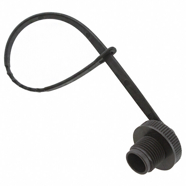
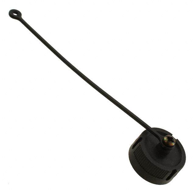
Cannon Trident Connectors Ringlock Circular Accessories How to Order-Accessories Typical Nomenclature: TR 10 A HC 1 N Series N = Nylon TR = Trident Ringlock Shell Size Series Identification 1 = Standard 10 12 14 HC = Sealed Cable Clamp 16 SR = Unsealed Cable Clamp 18 AD = Heat Shrink Adapter 20 22 24 A = Accessory How to Order-Dust Caps Typical Nomenclature: TNA 10 DCR0 - 00 B Material Series Packaging TNA = Trident Neptune Accessory B = Bulk L = Single Pack (Ringlock Compatible) Shell Size 10 Accessory Style, Type and Size 12 Dust Cap 14 16 DC R0-00 Unsealed Dust Cap, Receptacle (PAD)* 18 20 22 24 Dimensions shown in mm (inch) Specifications and dimensions subject to change www.ittcannon.com 29
Cannon Trident Connectors Ringlock Circular Accessories Unsealed Shell Part Number Part Number Dimension Size (Each) (Pack of 100) Ø A max. Plastic Dust Caps 10 192900-0666 192900-0676 21,80 (.858) for Receptacles 12 192900-0667 192900-0677 25,40 (1.000) 14 192900-0668 192900-0678 28,60 (1.126) • Protects unmated receptacles. 16 192900-0669 192900-0679 31,70 (1.248) • Durable construction for long-term use. 18 192900-0670 192900-0680 34,90 (1.374) 20 192900-0671 192900-0681 38,10 (1.500) • For use with Ringlock receptacles. 22 192900-0672 192900-0682 41,20 (1.622) 24 192900-0673 192900-0683 44,40 (1.748) Adapters for Heat Shrink Boots or Sleeving Part Number Dimensions Shell Size (Each) Nomenclature ØA ±0,3 (.012) ØB ±0,3 (.012) C ±0,3 (.012) H Thread 10 192990-1430 TR10AAD 21,00 (.827) 18,10 (.712) 19,20 (.755) 9/16 - 24 UNEF-2B 12 192990-1440 TR12AAD 24,00 (.944) 23,40 (.921) 19,20 (.755) 11/16 - 24 UNEF-2B 14 192990-1450 TR14AAD 27,00 (1.063) 24,20 (.952) 19,20 (.755) 13/16 - 20 UNEF-2B 16 192990-1460 TR16AAD 30,20 (1.189) 29,60 (1.165) 21,50 (.846) 15/16 - 20 UNEF-2B 18 192990-1470 TR18AAD 33,30 (1.311) 31,70 (1.248) 21,50 (.846) 1-1/16 - 18 UNEF-2B 20 192990-1480 TR20AAD 36,50 (1.437) 35,80 (1.409) 22,80 (.897) 1-3/16 - 18 UNEF-2B 22 192990-1490 TR22AAD 39,70 (1.563) 38,20 (1.503) 22,80 (.897) 1-5/16 - 18 UNEF-2B 24 192990-1500 TR24AAD 42,90 (1.689) 41,30 (1.626) 21,90 (.862) 1-7/16 - 18 UNEF-2B Shell Size Part Number (Pack of 100) 10 075-8543-011 12 075-8543-012 14 075-8543-013 16 075-8543-014 Panel Gaskets 18 075-8543-015 20 075-8543-016 for Ringlock Receptacles 22 075-8543-017 24 075-8543-018 • For sealed versions Dimensions shown in mm (inch) Specifications and dimensions subject to change www.ittcannon.com 30
Cannon Trident Connectors Ringlock Circular Accessories Sealed Cable Clamps for Use With Ringlock Circular Connectors • For use with jacketed cables. * For disassembly, add 9,00 (.354) for Shell Sizes 10-16 & add 10,60 (.417) for Shell Sizes 18-24. • Provides strain relief and wire protection. • Can be water sealed to IP65. See notes on pages 26 and 28. • For assembly instructions, see page 75. Part Number Dimensions Shell Size (Each) Nomenclature Ø A max. B ± 0,20 (.007) C* max. 10 192990-1530 TR10AHC1N 11,10 (.437) 18,80 (.740) 76,50 (3.011) 12 192990-1540 TR12AHC1N 13,60 (.535) 20,80 (.818) 77,80 (3.063) 14 192990-1550 TR14AHC1N 14,60 (.574) 22,80 (.897) 85,50 (3.366) 16 192990-1560 TR16AHC1N 16,60 (.653) 24,70 (.972) 89,80 (3.535) 18 192990-1570 TR18AHC1N 16,60 (.653) 24,70 (.972) 93,00 (3.661) 20 192990-1580 TR20AHC1N 22,10 (.870) 31,80 (1.252) 107,50 (4.232) 22 192990-1590 TR22AHC1N 22,10 (.870) 31,80 (1.252) 114,50 (4.507) 24 192990-1600 TR24AHC1N 29,60 (1.165) 41,80 (1.645) 128,50 (5.059) * Assumes a uniformly cylindrical cable. Variations in the diameter could effect sealing. * For disassembly, add 9,00 (.354) for Shell Sizes 10-16 & add 10,60 (.417) for Shell Sizes 18-24. Unsealed Cable Clamps for Use With Ringlock Circular Connectors • Provides strain relief and wire protection. • For assembly instructions, see page 79. Part Number Dimensions Shell Size (Each) Nomenclature Ø A max. B ± 0,15 (.005) ØC max. Ø D ± 0,15 (.005) E* max. 10 192922-1310 TR10ASR1N 21,50 (.846) 6,40 (.251) 8,70 (.342) 21,00 (.826) 61,30 (2.413) 12 192922-1320 TR12ASR1N 24,90 (.980) 6,40 (.251) 12,80 (.503) 24,00 (.944) 61,30 (2.413) 14 192922-1330 TR14ASR1N 27,00 (1.063) 6,40 (.251) 13,80 (.543) 27,00 (1.063) 67,10 (2.641) 16 192922-1340 TR16ASR1N 30,10 (1.185) 6,40 (.251) 17,00 (.669) 30,20 (1.189) 67,10 (2.641) 18 192990-1510 TR18ASR1N 32,00 (1.259) 7,00 (.275) 19,90 (.783) 33,20 (1.307) 70,80 (2.787) 20 192922-1350 TR20ASR1N 34,30 (1.350) 7,00 (.275) 21,00 (.827) 36,40 (1.433) 79,30 (3.122) 22 192922-1360 TR22ASR1N 37,10 (1.460) 8,20 (.322) 23,00 (.905) 39,60 (1.559) 85,30 (3.358) 24 192990-1520 TR24ASR1N 41,80 (1.645) 8,20 (.322) 27,00 (1.063) 42,80 (1.685) 90,80 (3.574) Dimensions shown in mm (inch) Specifications and dimensions subject to change www.ittcannon.com 31
Cannon Trident Connectors Neptune Circular Connectors Neptune is a range of circular connectors specifi- cally designed for harsh environment applications. They come with membrane wire seals that meet the requirements for IP67 and do not require blanking plugs for unused cavities. They will accept various combinations of signal (13 A) and power (30 A) contacts. The receptacle connectors feature stainless steel bayonet pins integrally molded into the bodies. The plug connectors are available with either high strength metal or corrosion resistant plastic coupling rings. All Neptune Circular Connectors are RoHS Compliant. Applications Product Features • Off Road Vehicles. • Mixes signal and 30 A power contacts in one housing. • Truck and Bus. • Printed circuit contacts available. • Agricultural Equipment. • Full interface and cable sealing up to IP67. • Construction Equipment. • Large range of support accessories. • Printing Machines. • Robust, cost effective connector for harsh environments. • Industrial Automation. • Stamping Machines. Performance Specifications Materials and Finishes - Operating Voltage1 Up to 250 V ac rms Connector Body Black Nylon Contact Current Rating2 Up to 13 A, Up to 16 A with High Conductivity Coupling Ring Nickel Plated Copper Alloy Contacts, Up to 30 A with Power Contacts Bayonet Pins Stainless Steel Bayonet Pins Support Band Nickel Plated Copper Alloy Operating Temperature -55°C to + 105°C (-67°F to +221°F) Insulation Resistance 5000MW min. at 500 V dc Durability3 Up to 500 Mating Cycles Environmental Sealing Up to IP67 Flammability UL 94 V-0 1 Depends on contacts used, layout, and degree of pollution 2 Depends on type and number of contacts used 3 Depends on plating and type of contacts used Dimensions shown in mm (inch) Specifications and dimensions subject to change www.ittcannon.com 32
Cannon Trident Connectors Neptune Circular Connectors Test Specifications The table below summarizes the results of key tests. Data is applicable to standard connectors with standard contacts. Variations may affect this data, so please consult factory for further information on your requirements. Test Method Criteria of Acceptance Dielectric Withstanding Voltage 2000 V ac for 60 seconds No breakdown Thermal Shock -55°C to +120°C (-67°F to +248°F) No physical damage Physical Shock 40 g’s peak, 3 axes, No physical damage. 6 millisecond duration half-sine pulse No loss of continuity >10 sec Vibration 10 g’s peak,10-500 Hz No physical damage, No loss of continuity >10 sec Durability 500 cycles of mating and unmating, No mechanical or 500 mating cycles max electrical defects Salt Spray 48 hours Shall be capable of mating and unmat ing and meet contact resistance requirements High Temperature Endurance 1000 hours at 85°C (+185°F) Insulation Resistance > 100 MW 250 hours at 120°C (+248°F) Humidy Steady State RH 90-95%, 40°C (+104°F), 504 hours Insulation Resistance > 100 MW How to Order-Connectors Typical Nomenclature: TN 7 S 24 - 1219 P 1 B 01 Series TN = Trident Neptune Modification * = Standard Shell Style 01= Jam Nut Receptacles bulk packages are delivered without nut 0 = Flange Receptacle (4 holes) See page 50 for Spare Jam Nuts 6 = Plug 7 = Jam Nut Receptacle Packaging B = Bulk (100 pcs) L = Single Pack Sealing Class Connector Finish Materials G = Grommet, no nut 1 = Standard (Nickel Plated Metal Parts) LS = Large Grommet, extender and nut (Size 24-0048 only) 2 = Plastic Coupling Nut (TN plug shell S = With Grommet and nut sizes 16 and 24 only) U = Unsealed Contact Type Shell Size and Contact Arrangement P = Pin S = Socket Number of Number of Shell Size Power Contacts Signal Contacts 14 - 00 12 16 - 00 19 16 - 02 13 24 - 12 19 24 - 04 20 24 - 04 28 24 - 00 48 Dimensions shown in mm (inch) Specifications and dimensions subject to change www.ittcannon.com 33
Cannon Trident Connectors Neptune Circular Connectors Contact Cavity Arrangements Neptune Circular Connectors offer combinations of Signal and Power contacts. The Signal cavities will accept any of the standard Trident contacts, including signal contacts up to 16 A. The power cavities will accept power contacts rated at 30 A. PCB contacts are also available, for more information, see page 60. Mating Face Views of Reversed and Standard Receptacles. Shell Size Number of Power Contacts Number of Signal Contacts Shell Size 14 Shell Size 16 Shell Size 16 0 Power 0 Power 2 Power 12 Signal 19 Signal 13 Signal The view is of reversed receptacle Standard receptacle is a mirror image Shell Size 24 Shell Size 24 Shell Size 24 Shell Size 24 12 Power 4 Power 4 Power 0 Power 19 Signal 20 Signal 28 Signal 48 Signal Note: The Signal cavities will accept any of the standard Trident contacts, including signal contacts up to 16 A. The power cavities will accept power contacts rated at 30 A. PCB contacts are also available. Wire Sealing Range* Contact Signal Power Arrangement (Overall Diameter) (Overall Diameter) (Power- Signal Contacts) 0-12 1,70-2,70 (.066-.106) N/A 0-19 1,70-2,70 (.066-.106) N/A 2-13 1,70-2,70 (.066-.106) 2,70-4,00 (.106-.157) 4-20 1,70-2,70 (.066-.106) 2,70-4,00 (.106-.157) 4-28 1,70-2,70 (.066-.106) 2,70-4,00 (.106-.157) 0-48 1,70-2,20 (.066-.086) N/A 0-48 (L) 2,60-3,20 (.102-.126) N/A 12-19 1,70-2,70 (.066-.106) 2,70-4,00 (.106-.157) (L) Larger overall sealing diameter for thick insulation wires * Describes the range of cable diameters to be used respective layout Dimensions shown in mm (inch) Specifications and dimensions subject to change www.ittcannon.com 34
Cannon Trident Connectors Neptune Circular Connectors Ø C Standard Plug for Pin Contacts Metal Locking Ring • For Wire Sealing Ranges, see page 34. • Accepts pin contacts, see page 60. • Water sealed to IP67. With Wire Seal and Securing Nut Bulk Packages Contact Layout Single Piece Connector (100 Connectors) Shell Power Signal Size Contacts Contacts Part Number Nomenclature Part Number Nomenclature A ØB ØC D 14 00 12 192900-0303 TN6S14-0012P1L 192900-0318 TN6S14-0012P1B 38,80 (1.527) 24,30 (.957) 28,00 (1.102) 19,10 ±0,20 (.751 ±.007) 16 00 19 192900-0017 TN6S16-0019P1L 192900-0013 TN6S16-0019P1B 38,90 (1.532) 27,00 (1.063) 30,20 (1.189) 19,10 ±0,20 (.751 ±.007) 16 02 13 192900-0507 TN6S16-0213P1L 192900-0510 TN6S16-0213P1B 38,90 (1.532) 27,00 (1.063) 30,20 (1.189) 19,10 ±0,20 (.751 ±.007) 24 00 48 192900-0469 TN6S24-0048P1L 192900-0472 TN6S24-0048P1B 39,80 (1.566) 40,50 (1.594) 44,00 (1.732) 14,72 ±0,15 (.580 ±.006) 24 04 20 192900-0014 TN6S24-0420P1L 192990-9430 TN6S24-0420P1B 39,80 (1.566) 40,50 (1.594) 44,00 (1.732) 14,72 ±0,15 (.580 ±.006) 24 04 28 192900-0015 TN6S24-0428P1L 192900-0012 TN6S24-0428P1B 39,80 (1.566) 40,50 (1.594) 44,00 (1.732) 14,72 ±0,15 (.580 ±.006) 24 12 19 192900-0016 TN6S24-1219P1L 192990-9380 TN6S24-1219P1B 39,80 (1.566) 40,50 (1.594) 44,00 (1.732) 14,72 ±0,15 (.580 ±.006) 24 00 48 (L) 192991-0628 TN6LS24-0048P1L 192991-0637 TN6LS24-0048P1B 50,70 (2.000) 40,50 (1.594) 44,00 (1.732) 14,72 ±0,15 (.580 ±.006) Without Securing Nut Contact Layout Bulk Packages Shell Power Signal Single Piece Connector (100 Connectors) Size Contacts Contacts Part Number Nomenclature Part Number Nomenclature A ØB ØC D 14 00 12 * TN6G14-0012P1L 192900-0319 TN6G14-0012P1B - 13/16 – 20 UNEF 28,00 (1.102) 19,10 ±0,20 (.751 ±.007) 16 00 19 * TN6G16-0019P1L 192900-0095 TN6G16-0019P1B - 15/16 – 20 UNEF 30,20 (1.189) 19,10 ±0,20 (.751 ±.007) 24 00 48 * TN6G24-0048P1L 192900-0473 TN6G24-0048P1B - 1-7/16 – 18 UNEF 44,00 (1.732) 14,72 ±0,15 (.580 ±.006) 24 04 20 * TN6G24-0420P1L 192900-0092 TN6G24-0420P1B - 1-7/16 – 18 UNEF 44,00 (1.732) 14,72 ±0,15 (.580 ±.006) 24 04 28 * TN6G24-0428P1L 192990-0093 TN6G24-0428P1B - 1-7/16 – 18 UNEF 44,00 (1.732) 14,72 ±0,15 (.580 ±.006) 24 12 19 * TN6G24-1219P1L 192900-0094 TN6G24-1219P1B - 1-7/16 – 18 UNEF 44,00 (1.732) 14,72 ±0,15 (.580 ±.006) Unsealed - Without Wire Seal and Securing Nut Bulk Packages Contact Layout Shell Power Signal Single Piece Connector (100 Connectors) Size Contacts Contacts Part Number Nomenclature Part Number Nomenclature A ØB ØC D 16 02 13 * TN6U16-0213P1L * TN6U16-0213P1B 34,70 (1.366) 15/16 – 20 UNEF 30,20 (1.189) 19,10 ±0,20 (.751 ±.007) 24 04 20 * TN6U24-0420P1L * TN6U24-0420P1B 35,70 (1.406) 1-7/16 – 18 UNEF 44,00 (1.732) 14,72 ±0,15 (.580 ±.006) 24 04 28 * TN6U24-0428P1L * TN6U24-0428P1B 35,70 (1.406) 1-7/16 – 18 UNEF 44,00 (1.732) 14,72 ±0,15 (.580 ±.006) 24 12 19 * TN6U24-1219P1L * TN6U24-1219P1B 35,70 (1.406) 1-7/16 – 18 UNEF 44,00 (1.732) 14,72 ±0,15 (.580 ±.006) * For details please consult the factory Dimensions shown in mm (inch) Specifications and dimensions subject to change www.ittcannon.com 35
Cannon Trident Connectors Neptune Circular Connectors Ø C Standard Plug for Pin Contacts Plastic Locking Ring • For Wire Sealing Ranges, see page 34. • Accepts pin contacts, see page 60. • Water sealed to IP67. With Wire Seal and Securing Nut Bulk Packages Contact Layout Single Piece Connector (100 Connectors) Shell Power Signal Size Contacts Contacts Part Number Nomenclature Part Number Nomenclature A ØB ØC 16 00 19 192900-0557 TN6S16-0019P2L * TN6S16-0019P2B 38,90 (1.532) 27,00 (1.063) 32,80 (1.291) 16 02 13 192900-0561 TN6S16-0213P2L * TN6S16-0213P2B 38,90 (1.532) 27,00 (1.063) 32,80 (1.291) 24 00 48 192900-0539 TN6S24-0048P2L * TN6S24-0048P2B 39,80 (1.566) 40,50 (1.594) 45,75 (1.800) 24 04 20 192900-0537 TN6S24-0420P2L * TN6S24-0420P2B 39,80 (1.566) 40,50 (1.594) 45,75 (1.800) 24 04 28 192900-0549 TN6S24-0428P2L 192900-0551 TN6S24-0428P2B 39,80 (1.566) 40,50 (1.594) 45,75 (1.800) 24 12 19 192900-0538 TN6S24-1219P2L * TN6S24-1219P2B 39,80 (1.566) 40,50 (1.594) 45,75 (1.800) 24 00 48 (L) 192991-0660 TN6LS24-0048P2L * TN6LS24-0048P2B 50,70 (2.000) 40,50 (1.594) 45,75 (1.800) Unsealed - Without Wire Seal and Securing Nut Contact Layout Bulk Packages Shell Power Signal Single Piece Connector (100 Connectors) Size Contacts Contacts Part Number Nomenclature Part Number Nomenclature A ØB ØC 16 02 13 * TN6U16-0213P2L * TN6U16-0213P2B 34,70 (1.366) 15/16 – 20 UNEF 32,80 (1.291) 24 04 20 * TN6U24-0420P2L * TN6U24-0420P2B 35,70 (1.406) 1-7/16 – 18 UNEF 45,75 (1.800) 24 04 28 * TN6U24-0428P2L 192900-0692 TN6U24-0428P2B 35,70 (1.406) 1-7/16 – 18 UNEF 45,75 (1.800) 24 12 19 * TN6U24-1219P2L 192900-0691 TN6U24-1219P2B 35,70 (1.406) 1-7/16 – 18 UNEF 45,75 (1.800) * For details please consult the factory Dimensions shown in mm (inch) Specifications and dimensions subject to change www.ittcannon.com 36
Cannon Trident Connectors Neptune Circular Connectors Panel Cutout F G G F Standard Receptacle for Socket Contacts Flange Mounting Ø H ØJ = Flange in Front of Panel ØK = Flange at Rear of Panel • For Wire Sealing Ranges, see page 34. • 3,00 (.118) max with Panel Gasket. • For Panel Gaskets, see page 47. With Wire Seal and Securing Nut Bulk Packages Contact Layout Shell Power Signal Single Piece Connector (100 Connectors) Size Contacts Contacts Part Number Nomenclature Part Number Nomenclature A B C ØD ØE F G ØH ØJ ØK 14 00 12 192900-0308 TN0S14-0012S1L 192900-0323 TN0S14-0012S1B 39,70 3,50 11,40 22,20 24,30 28,60 22,90 3,20 24,60 24,60 (1.563) (.137) (.448) (.874) (.956) (1.122) (.901) (.125) (.968) (.968) 16 00 19 192900-0039 TN0S16-0019S1L 192900-0029 TN0S16-0019S1B 39,80 2,30 11,40 25,40 27,00 31,00 24,50 3,20 28,10 28,10 (1.566) (.090) (.448) (1.000) (1.063) (1.220) (.964) (.125) (1.106) (1.106) 16 02 13 192900-0509 TN0S16-0213S1L 192900-0512 TN0S16-0213S1B 39,80 2,30 11,40 25,40 27,00 31,00 24,50 3.20 28,10 28,10 (1.566) (.090) (.448) (1.000) (1.063) (1.220) (.964) (.125) (1.106) (1.106) 24 00 48 192900-0475 TN0S24-0048S1L 192900-0478 TN0S24-0048S1B 41,80 3,50 15,40 38,10 40,10 50,80 39,70 4,20 41,00 41,00 (1.645) (.137) (.606) (1.500) (1,578) (2.000) (1.563) (.165) (1.614) (1.614) 24 04 20 192900-0030 TN0S24-0420S1L 192990-9420 TN0S24-0420S1B 41,80 3,50 15,40 38,10 40,10 50,80 39,70 4,20 41,00 41,00 (1.645) (.137) (.606) (1.500) (1,578) (2.000) (1.563) (.165) (1.614) (1.614) 24 04 28 192900-0033 TN0S24-0428S1L 192900-0024 TN0S24-0428S1B 41,80 3,50 15,40 38,10 40,10 50,80 39,70 4,20 41,00 41,00 (1.645) (.137) (.606) (1.500) (1,578) (2.000) (1.563) (.165) (1.614) (1.614) 24 12 19 192900-0036 TN0S24-1219S1L 192990-9390 TN0S24-1219S1B 41,80 3,50 15,40 38,10 40,10 50,80 39,70 4,20 41,00 41,00 (1.645) (.137) (.606) (1.500) (1,578) (2.000) (1.563) (.165) (1.614) (1.614) 24 00 48 (L) 192991-0640 TN0LS24-0048S1L * TN0LS24-0048S1B 52,70 3,50 15,40 38,10 40,10 50,80 39,70 4,20 41,00 41,00 (2.075) (.137) (.606) (1.500) (1,578) (2.000) (1.563) (.165) (1.614) (1.614) Without Securing Nut Bulk Packages Contact Layout Shell Power Signal Single Piece Connector (100 Connectors) Size Contacts Contacts Part Number Nomenclature Part Number Nomenclature A B C ØD ØE F G ØH ØJ ØK 14 00 12 * TN0G14-0012S1L 192900-0324 TN0G14-0012S1B - 2,30 11,40 22,20 13/16 – 20 UNEF 28,60 22,90 3,20 24,60 24,60 (.090) (.448) (.874) (1.122) (.901) (.125) (.968) (.968) 16 00 19 * TN0G16-0019S1L 192900-0105 TN0G16-0019S1B - 2,30 11,40 25,40 15/16 – 20 UNEF 31,00 24,50 3,20 28,10 28,10 (.090) (.448) (1.000) (1.220) (.964) (.125) (1.106) (1.106) 24 00 48 192900-0479 TN0G24-0048S1L * TN0G24-0048S1B - 3,50 15,40 38,18 1-7/16 – 18 UNEF 50,80 39,70 4,20 41,00 41,00 (.137) (.606) (1.500) (2.000) (1.563) (.165) (1.614) (1.614) 24 04 20 * TN0G24-0420S1L 192900-0096 TN0G24-0420S1B - 3,50 15,40 38,18 1-7/16 – 18 UNEF 50,80 39,70 4,20 41,00 41,00 (.137) (.606) (1.500) (2.000) (1.563) (.165) (1.614) (1.614) 24 04 28 * TN0G24-0428S1L 192900-0099 TN0G24-0428S1B - 3,50 15,40 38,18 1-7/16 – 18 UNEF 50,80 39,70 4,20 41,00 41,00 (.137) (.606) (1.500) (2.000) (1.563) (.165) (1.614) (1.614) 24 12 19 * TN0G24-1219S1L 192900-0102 TN0G24-1219S1B - 3,50 15,40 38,18 1-7/16 – 18 UNEF 50,80 39,70 4,20 41,00 41,00 (.137) (.606) (1.500) (2.000) (1.563) (.165) (1.614) (1.614) * For details please consult the factory Dimensions shown in mm (inch) Specifications and dimensions subject to change www.ittcannon.com 37
Cannon Trident Connectors Neptune Circular Connectors Panel Cutout Ø F G Standard Receptacle for Socket Contacts • Bulk packages are not supplied with Jam Nuts, • Panel thickness 4,00 (.157) max. Jam Nut Mounting to order Jam Nuts, see page 46. • 3,00 (.118) max with Panel gasket. • For Wire Sealing Ranges, see page 34. With Wire Seal and Securing Nut • For Panel Gaskets, see page 47. Bulk Packages Contact Layout Shell Power Signal Single Piece Connector (100 Connectors) Size Contacts Contacts Part Number Nomenclature Part Number Nomenclature A B C ØD ØE ØF G H ØJ 14 00 12 192900-0313 TN7S14-0012S1L 192900-0328 TN7S14-0012S1B01 39,70 3,50 22,10 22,20 24,30 35,80 32,20 25,10 27,30 (1.563) (.137) (.870) (.874) (.956) (1.409) (1.267) (.988) (1.075) 16 00 19 192900-0490 TN7S16-0019S1L 192900-0493 TN7S16-0019S1B01 39,80 2,30 23,00 25,40 27,00 39,80 38,40 28,00 30,50 (1.566) (.090) (.905) (1.000) (1.063) (1.566) (1,511) (1.102) (1.200) 16 02 13 192900-0508 TN7S16-0213S1L 192900-0511 TN7S16-0213S1B01 39,80 2,30 23,00 25,40 27,00 39,80 38,40 28,00 30,50 (1.566) (.090) (.905) (1.000) (1.063) (1.566) (1.511) (1.102) (1.200) 24 00 48 192900-0481 TN7S24-0048S1L 192900-0484 TN7S24-0048S1B01 41,80 3,50 23,40 38,10 40,10 51,00 47,50 41,50 43,20 (1.645) (.137) (.921) (1.500) (1,578) (2.007) (1.870) (1.633) (1.700) 24 04 20 192900-0032 TN7S24-0420S1L 192990-9460 TN7S24-0420S1B01 41,80 3,50 23,40 38,10 40,10 51,00 47,50 41,50 43,20 (1.645) (.137) (.921) (1.500) (1,578) (2.007) (1.870) (1.633) (1.700) 24 04 28 192900-0035 TN7S24-0428S1L 192900-0026 TN7S24-0428S1B01 41,80 3,50 23,40 38,10 40,10 51,00 47,50 41,50 43,20 (1.645) (.137) (.921) (1.500) (1,578) (2.007) (1.870) (1.633) (1.700) 24 12 19 192900-0038 TN7S24-1219S1L 192900-0028 TN7S24-1219S1B01 41,80 3,50 23,40 38,10 40,10 51,00 47,50 41,50 43,20 (1.645) (.137) (.921) (1.500) (1,578) (2.007) (1.870) (1.633) (1.700) 24 00 48 (L) 192991-0644 TN7LS24-0048S1L * TN7LS24-0048S1B01 52,70 3,50 23,40 38,10 40,10 51,00 47,50 41,50 43,20 (2.075) (.137) (921) (1.500) (1,578) (2.007) (1.870) (1.633) (1.700) Without Securing Nut Bulk Packages Contact Layout Shell Power Signal Single Piece Connector (100 Connectors) Size Contacts Contacts Part Number Nomenclature Part Number Nomenclature A B C ØD ØE ØF G H ØJ 14 00 12 * TN7G14-0012S1L 192900-0329 TN7G14-0012S1B01 - 2,30 22,10 22,20 13/16 – 20 UNEF 35,80 32,20 25,10 27,30 (.090) (.870) (.874) (1.409) (1.267) (.988) (1.075) 16 00 19 * TN7G16-0019S1L * TN7G16-0019S1B01 - 2,30 23,00 25,40 15/16 – 20 UNEF 39,80 38,40 28,00 30,50 (.090) (.905) (1.000) (1.566) (1,511) (1.102) (1.200) 24 00 48 * TN7G24-0048S1L * TN7G24-0048S1B01 - 3,50 23,40 38,10 1-7/16 – 18 UNEF 51,00 47,50 41,50 43,20 (.137) (.921) (1.500) (2.007) (1.870) (1.633) (1.700) 24 04 20 * TN7G24-0420S1L 192900-0098 TN7G24-0420S1B01 - 3,50 23,40 38,10 1-7/16 – 18 UNEF 51,00 47,50 41,50 43,20 (.137) (.921) (1.500) (2.007) (1.870) (1.633) (1.700) 24 04 28 * TN7G24-0428S1L 192900-0101 TN7G24-0428S1B01 - 3,50 23,40 38,10 1-7/16 – 18 UNEF 51,00 47,50 41,50 43,20 (.137) (.921) (1.500) (2.007) (1.870) (1.633) (1.700) 24 12 19 * TN7G24-1219S1L 192900-0104 TN7G24-1219S1B01 - 3,50 23,40 38,10 1-7/16 – 18 UNEF 51,00 47,50 41,50 43,20 (.137) (.921) (1.500) (2.007) (1.870) (1.633) (1.700) Unsealed - Without Wire Seal and Securing Nut Bulk Packages Contact Layout Single Piece Connector (100 Connectors) Shell Power Signal Part Part Size Contacts Contacts Number Nomenclature Number Nomenclature A B C ØD ØE ØF G H ØJ 16 02 13 * TN7U16-0213S1L * TN7U16-0213S1B01 35,60 (1.402) 2,30(.090) 23,00(.905) 25,40(1.000) 15/16 – 20 UNEF 39,80(1.566) 38,40(1,511) 28,00(1,511) 30,50(1.200) 24 04 20 * TN7U24-0420S1L * TN7U24-0420S1B01 37,65 (1.482) 3,50(.137) 23,40(.921) 38,10(1.500) 1-7/16 – 18 UNEF 51,00(2.007) 47,50(1.870) 41,50(1.633) 43,20(1.700) 24 04 28 * TN7U24-0428S1L * TN7U24-0428S1B01 37,65 (1.482) 3,50(.137) 23,40(.921) 38,10(1.500) 1-7/16 – 18 UNEF 51,00(2.007) 47,50(1.870) 41,50(1.633) 43,20(1.700) 24 12 19 * TN7U24-1219S1L * TN7U24-1219S1B01 37,65 (1.482) 3,50(.137) 23,40(.921) 38,10(1.500) 1-7/16 – 18 UNEF 51,00(2.007) 47,50(1.870) 41,50(1.633) 43,20(1.700) * For details please consult the factory Dimensions shown in mm (inch) Specifications and dimensions subject to change www.ittcannon.com 38
Cannon Trident Connectors Neptune Circular Connectors Reversed Plugs for Socket Contacts Metal Locking Ring • For Wire Sealing Ranges, see page 34. • Accepts socket contacts, see page 60. • Water sealed to IP67. With Wire Seal and Securing Nut Bulk Packages Contact Layout Single Piece Connector (100 Connectors) Shell Power Signal Size Contacts Contacts Part Number Nomenclature Part Number Nomenclature A ØB ØC D 14 00 12 192900-0236 TN6S14-0012S1L 192900-0241 TN6S14-0012S1B 31,60 (1.244) 24,30 (.957) 28,00 (1.102) 19,10 ±0,20 (.751 ±.007) 16 00 19 192900-0057 TN6S16-0019S1L 192990-9970 TN6S16-0019S1B 31,70 (1.248) 27,00 (1.063) 30,20 (1.189) 19,10 ±0,20 (.751 ±.007) 16 02 13 192900-0581 TN6S16-0213S1L * TN6S16-0213S1B 31,70 (1.248) 27,00 (1.063) 30,20 (1.189) 19,10 ±0,20 (.751 ±.007) 24 00 48 192900-0425 TN6S24-0048S1L 192900-0428 TN6S24-0048S1B 32,40 (1.275) 40,50 (1.594) 44,00 (1.732) 14,72 ±0,15 (.580 ±.006) 24 04 20 192900-0054 TN6S24-0420S1L 192990-9450 TN6S24-0420S1B 32,40 (1.275) 40,50 (1.594) 44,00 (1.732) 14,72 ±0,15 (.580 ±.006) 24 04 28 192900-0055 TN6S24-0428S1L 192900-0053 TN6S24-0428S1B 32,40 (1.275) 40,50 (1.594) 44,00 (1.732) 14,72 ±0,15 (.580 ±.006) 24 12 19 192900-0056 TN6S24-1219S1L 192990-9240 TN6S24-1219S1B 32,40 (1.275) 40,50 (1.594) 44,00 (1.732) 14,72 ±0,15 (.580 ±.006) 24 00 48 (L) 192991-0648 TN6LS24-0048S1L * TN6LS24-0048S1B 43,00 (1.693) 40,50 (1.594) 44,00 (1.732) 14,72 ±0,15 (.580 ±.006) Without Securing Nut Bulk Packages Contact Layout Single Piece Connector (100 Connectors) Shell Power Signal Size Contacts Contacts Part Number Nomenclature Part Number Nomenclature A ØB ØC D 14 00 12 * TN6G14-0012S1L 192900-0242 TN6G14-0012S1B - 13/16–20 UNEF 28,00 (1.102) 19,10 ±0,20 (.751 ±.007) 16 00 19 * TN6G16-0019S1L 192900-0109 TN6G16-0019S1B - 15/16–20 UNEF 30,20 (1.189) 19,10 ±0,20 (.751 ±.007) 24 00 48 * TN6G24-0048S1L 192900-0429 TN6G24-0048S1B - 1-7/16–18 UNEF 44,00 (1.732) 14,72 ±0,15 (.580 ±.006) 24 04 20 * TN6G24-0420S1L 192900-0106 TN6G24-0420S1B - 1-7/16–18 UNEF 44,00 (1.732) 14,72 ±0,15 (.580 ±.006) 24 04 28 * TN6G24-0428S1L 192900-0107 TN6G24-0428S1B - 1-7/16–18 UNEF 44,00 (1.732) 14,72 ±0,15 (.580 ±.006) 24 12 19 * TN6G24-1219S1L 192900-0108 TN6G24-1219S1B - 1-7/16–18 UNEF 44,00 (1.732) 14,72 ±0,15 (.580 ±.006) Unsealed - Without Wire Seal and Securing Nut Bulk Packages Contact Layout Single Piece Connector (100 Connectors) Shell Power Signal Size Contacts Contacts Part Number Nomenclature Part Number Nomenclature A ØB ØC D 16 02 13 * TN6U16-0213S1L * TN6U16-0213S1B 27,55 (1.085) 15/16–20 UNEF 30,20 (1.189) 19,10 ±0,20 (.751 ±.007) 24 04 20 * TN6U24-0420S1L * TN6U24-0420S1B 28,10 (1.106) 1-7/16–18 UNEF 44,00 (1.732) 14,72 ±0,15 (.580 ±.006) 24 04 28 * TN6U24-0428S1L * TN6U24-0428S1B 28,10 (1.106) 1-7/16–18 UNEF 44,00 (1.732) 14,72 ±0,15 (.580 ±.006) 24 12 19 * TN6U24-1219S1L * TN6U24-1219S1B 28,10 (1.106) 1-7/16–18 UNEF 44,00 (1.732) 14,72 ±0,15 (.580 ±.006) * For details please consult the factory Dimensions shown in mm (inch) Specifications and dimensions subject to change www.ittcannon.com 39
Cannon Trident Connectors Neptune Circular Connectors Reversed Plugs for Socket Contacts Plastic Locking Ring • For Wire Sealing Ranges, see page 34. • Accepts socket contacts, see page 60. • Water sealed to IP67. With Wire Seal and Securing Nut Bulk Packages Contact Layout Single Piece Connector (100 Connectors) Shell Power Signal Size Contacts Contacts Part Number Nomenclature Part Number Nomenclature A ØB ØC 16 00 19 192900-0558 TN6S16-0019S2L 192900-0560 TN6S16-0019S2B 31,70 (1.248) 27,00 (1.063) 32,80 (1.291) 16 02 13 192900-0562 TN6S16-0213S2L 192900-0564 TN6S16-0213S2B 31,70 (1.248) 27,00 (1.063) 32,80 (1.291) 24 00 48 192900-0542 TN6S24-0048S2L 192900-0548 TN6S24-0048S2B 32,40 (1.275) 40,50 (1.594) 44,00 (1.732) 24 04 20 192900-0540 TN6S24-0420S2L * TN6S24-0420S2B 32,40 (1.275) 40,50 (1.594) 44,00 (1.732) 24 04 28 192900-0550 TN6S24-0428S2L 192900-0552 TN6S24-0428S2B 32,40 (1.275) 40,50 (1.594) 44,00 (1.732) 24 12 19 192900-0541 TN6S24-1219S2L 192900-0547 TN6S24-1219S2B 32,40 (1.275) 40,50 (1.594) 44,00 (1.732) 24 00 48 (L) 192991-0664 TN6LS24-0048S2L * TN6LS24-0048S2B 43,00 (1.693) 40,50 (1.594) 44,00 (1.732) Unsealed - Without Wire Seal and Securing Nut Contact Layout Bulk Packages Shell Power Signal Single Piece Connector (100 Connectors) Size Contacts Contacts Part Number Nomenclature Part Number Nomenclature A ØB ØC 16 02 13 * TN6U16-0213S2L * TN6U16-0213S2B 27,55 (1.085) 15/16 – 20 UNEF 32,80 (1.291) 24 04 20 * TN6U24-0420S2L * TN6U24-0420S2B 28,10 (1.106) 1-7/16 – 18 UNEF 44,00 (1.732) 24 04 28 * TN6U24-0428S2L * TN6U24-0428S2B 28,10 (1.106) 1-7/16 – 18 UNEF 44,00 (1.732) 24 12 19 * TN6U24-1219S2L * TN6U24-1219S2B 28,10 (1.106) 1-7/16 – 18 UNEF 44,00 (1.732) * For details please consult the factory Dimensions shown in mm (inch) Specifications and dimensions subject to change www.ittcannon.com 40
Cannon Trident Connectors Neptune Circular Connectors Panel Cutout Reversed Receptacle for Pin Contacts Flange Mounting ØJ = Flange in Front of Panel ØK = Flange at Rear of Panel • For Wire Sealing Ranges, see page 34. • 3,00 (.118) max with Panel Gasket. For Panel Gaskets, see page 47. With Wire Seal and Securing Nut Bulk Packages Contact Layout Shell Power Signal Single Piece Connector (100 Connectors) Size Contacts Contacts Part Number Nomenclature Part Number Nomenclature A B C ØD ØE F G ØH ØJ ØK 14 00 12 192900-0256 TN0S14-0012P1L 192900-0261 TN0S14-0012P1B 39,70 2,30 11,40 22,20 24,30 28,60 22,90 3,20 24,60 24,60 (1.563) (.090) (.448) (.874) (.956) (1.122) (.901) (.125) (.968) (.968) 16 00 19 192900-0078 TN0S16-0019P1L 192990-9980 TN0S16-0019P1B 39,80 2,30 11,40 25,40 27,00 31,00 24,50 3,20 28,10 28,10 (1.566) (.090) (.448) (1.000) (1.063) (1.220) (.964) (.125) (1.106) (1.106) 16 02 13 192900-0582 TN0S16-0213P1L * TN0S16-0213P1B 39,80 2,30 11,40 25,40 27,00 31,00 24,50 3.20 28,10 28,10 (1.566) (.090) (.448) (1.000) (1.063) (1.220) (.964) (.125) (1.106) (1.106) 24 00 48 192900-0431 TN0S24-0048P1L 192900-0434 TN0S24-0048P1B 41,80 3,50 15,40 38,10 40,10 50,80 39,70 4,20 41,00 41,00 (1.645) (.137) (.606) (1.500) (1,578) (2.000) (1.563) (.165) (1.614) (1.614) 24 04 20 192900-0069 TN0S24-0420P1L 192990-9440 TN0S24-0420P1B 41,80 3,50 15,40 38,10 40,10 50,80 39,70 4,20 41,00 41,00 (1.645) (.137) (.606) (1.500) (1,578) (2.000) (1.563) (.165) (1.614) (1.614) 24 04 28 192900-0072 TN0S24-0428P1L 192900-0064 TN0S24-0428P1B 41,80 3,50 15,40 38,10 40,10 50,80 39,70 4,20 41,00 41,00 (1.645) (.137) (.606) (1.500) (1,578) (2.000) (1.563) (.165) (1.614) (1.614) 24 12 19 192900-0075 TN0S24-1219P1L 192990-9250 TN0S24-1219P1B 41,80 3,50 15,40 38,10 40,10 50,80 39,70 4,20 41,00 41,00 (1.645) (.137) (.606) (1.500) (1,578) (2.000) (1.563) (.165) (1.614) (1.614) 24 00 48 (L) 192991-0652 TN0LS24-0048P1L * TN0LS24-0048P1B 52,70 3,50 15,40 38,10 40,10 50,80 39,70 4,20 41,00 41,00 (2.075) (.137) (.606) (1.500) (1,578) (2.000) (1.563) (.165) (1.614) (1.614) Without Securing Nut Contact Layout Bulk Packages Shell Power Signal Single Piece Connector (100 Connectors) Size Contacts Contacts Part Number Nomenclature Part Number Nomenclature A B C ØD ØE F G ØH ØJ ØK 14 00 12 * TN0G14-0012P1L 192900-0262 TN0G14-0012P1B - 2,30 11,40 22,20 15/16 – 20 UNEF 28,60 22,90 3,20 24,60 24,60 (.090) (.448) (.874) (1.122) (.901) (.125) (.968) (.968) 16 00 19 * TN0G16-0019P1L 192900-0119 TN0G16-0019P1B - 2,30 11,40 25,40 15/16 – 20 UNEF 31,00 24,50 3,20 28,10 28,10 (.090) (.448) (1.000) (1.220) (.964) (.125) (1.106) (1.106) 24 00 48 * TN0G24-0048P1L 192900-0435 TN0G24-0048P1B - 3,50 15,40 38,10 1-7/16 – 18 UNEF 50,80 39,70 4,20 41,00 41,00 (.137) (.606) (1.500) (2.000) (1.563) (.165) (1.614) (1.614) 24 04 20 * TN0G24-0420P1L 192900-0110 TN0G24-0420P1B - 3,50 15,40 38,10 1-7/16 – 18 UNEF 50,80 39,70 4,20 41,00 41,00 (.137) (.606) (1.500) (2.000) (1.563) (.165) (1.614) (1.614) 24 04 28 * TN0G24-0428P1L 192900-0113 TN0G24-0428P1B - 3,50 15,40 38,10 1-7/16 – 18 UNEF 50,80 39,70 4,20 41,00 41,00 (.137) (.606) (1.500) (2.000) (1.563) (.165) (1.614) (1.614) 24 12 19 * TN0G24-1219P1L 192900-0116 TN0G24-1219P1B - 3,50 15,40 38,10 1-7/16 – 18 UNEF 50,80 39,70 4,20 41,00 41,00 (.137) (.606) (1.500) (2.000) (1.563) (.165) (1.614) (1.614) * For details please consult the factory Dimensions shown in mm (inch) Specifications and dimensions subject to change www.ittcannon.com 41
Cannon Trident Connectors Neptune Circular Connectors Panel Cutout Reversed Receptacle for Pin Contacts Jam Nut Mounting • For Wire Sealing Ranges, see page 34. • Panel thickness 4,00 (.157) max • 3,00 (.118) max with Panel gasket. With Wire Seal and Securing Nut • For Panel Gaskets, see page 47. • Bulk packages are not supplied with Jam Bulk Packages Contact Layout Nuts. To order Jam Nuts see page 47. Shell Power Signal Single Piece Connector (100 Connectors) Size Contacts Contacts Part Number Nomenclature Part Number Nomenclature A B C ØD ØE ØF G H ØJ 14 00 12 192900-0266 TN7S14-0012P1L 192900-0271 TN7S14-0012P1B01 39,70 3,50 22,10 22,20 24,30 35,80 32,20 25,10 27,30 (1.563) (.137) (.870) (.874) (.956) (1.409) (1.267) (.988) (1.075) 16 00 19 192900-0353 TN7S16-0019P1L 192900-0395 TN7S16-0019P1B01 39,80 2,30 23,00 25,40 27,00 39,80 38,40 28,00 30,50 (1.566) (.090) (.905) (1.000) (1.063) (1.566) (1,511) (1.102) (1.200) 16 02 13 192900-0583 TN7S16-0213P1L 192900-0586 TN7S16-0213P1B01 39,80 2,30 23,00 25,40 27,00 39,80 38,40 28,00 30,50 (1.566) (.090) (.905) (1.000) (1.063) (1.566) (1.511) (1.102) (1.200) 24 00 48 192900-0437 TN7S24-0048P1L 192900-0440 TN7S24-0048P1B01 41,80 3,50 23,40 38,10 40,10 51,00 47,50 41,50 43,20 (1.645) (.137) (.921) (1.500) (1,578) (2.007) (1.870) (1.633) (1.700) 24 04 20 192900-0071 TN7S24-0420P1L 192990-9470 TN7S24-0420P1B01 41,80 3,50 23,40 38,10 40,10 51,00 47,50 41,50 43,20 (1.645) (.137) (.921) (1.500) (1,578) (2.007) (1.870) (1.633) (1.700) 24 04 28 192900-0074 TN7S24-0428P1L 192900-0066 TN7S24-0428P1B01 41,80 3,50 23,40 38,10 40,10 51,00 47,50 41,50 43,20 (1.645) (.137) (.921) (1.500) (1,578) (2.007) (1.870) (1.633) (1.700) 24 12 19 192900-0077 TN7S24-1219P1L 192900-0068 TN7S24-1219P1B01 41,80 3,50 23,40 38,10 40,10 51,00 47,50 41,50 43,20 (1.645) (.137) (.921) (1.500) (1,578) (2.007) (1.870) (1.633) (1.700) 24 00 48 (L) 192991-0656 TN7LS24-0048P1L * TN7LS24-0048P1B01 52,70 3,50 23,40 38,10 40,10 51,00 47,50 41,50 43,20 (2.075) (.137) (921) (1.500) (1,578) (2.007) (1.870) (1.633) (1.700) Without Securing Nut Bulk Packages Contact Layout Shell Power Signal Single Piece Connector (100 Connectors) Size Contacts Contacts Part Number Nomenclature Part Number Nomenclature A B C ØD ØE ØF G H ØJ 14 00 12 * TN7G14-0012P1L 192900-0370 TN7G14-0012P1B01 - 2,30 22,10 22,20 15/16 – 20 UNEF 35,80 32,20 25,10 27,30 (.090) (.870) (.874) (1.409) (1.267) (.988) (1.075) 16 00 19 * TN7G16-0019P1L 192900-0396 TN7G16-0019P1B01 - 2,30 23,00 25,40 15/16 – 20 UNEF 39,80 38,40 28,00 30,50 (.090) (.905) (1.000) (1.566) (1,511) (1.102) (1.200) 24 00 48 192900-0438 TN7G24-0048P1L 192900-0441 TN7G24-0048P1B01 - 3,50 23,40 38,10 1-7/16 – 18 UNEF 51,00 47,50 41,50 43,20 (.137) (.921) (1.500) (2.007) (1.870) (1.633) (1.700) 24 04 20 * TN7G24-0420P1L 192900-0112 TN7G24-0420P1B01 - 3,50 23,40 38,10 1-7/16 – 18 UNEF 51,00 47,50 41,50 43,20 (.137) (.921) (1.500) (2.007) (1.870) (1.633) (1.700) 24 04 28 * TN7G24-0428P1L 192900-0115 TN7G24-0428P1B01 - 3,50 23,40 38,10 1-7/16 – 18 UNEF 51,00 47,50 41,50 43,20 (.137) (.921) (1.500) (2.007) (1.870) (1.633) (1.700) 24 12 19 * TN7G24-1219P1L 192900-0118 TN7G24-1219P1B01 - 3,50 23,40 38,10 1-7/16 – 18 UNEF 51,00 47,50 41,50 43,20 (.137) (.921) (1.500) (2.007) (1.870) (1.633) (1.700) Unsealed- Without Wire Seal and Securing Nut Contact Layout Bulk Packages Shell Power Signal Single Piece Connector (100 Connectors) Size Contacts Contacts Part Number Nomenclature Part Number Nomenclature A B C ØD ØE ØF G H ØJ 16 02 13 * TN7U16-0213P1L * TN7U16-0213P1B01 35,60 2,30 23,00 25,40 15/16 – 20 UNEF 39,80 38,40 28,00 30,50 (1.402) (.090) (.905) (1.000) (1.566) (1,511) (1.102) (1.200) 24 04 20 * TN7U24-0420P1L * TN7U24-0420P1B01 37,65 3,50 23,40 38,10 1-7/16 – 18 UNEF 51,00 47,50 41,50 43,20 (1.482) (.137) (.921) (1.500) (2.007) (1.870) (1.633) (1.700) 24 04 28 * TN7U24-0428P1L * TN7U24-0428P1B01 37,65 3,50 23,40 38,10 1-7/16 – 18 UNEF 51,00 47,50 41,50 43,20 (1.482) (.137) (.921) (1.500) (2.007) (1.870) (1.633) (1.700) 24 12 19 * TN7U24-1219P1L * TN7U24-1219P1B01 37,65 3,50 23,40 38,10 1-7/16 – 18 UNEF 51,00 47,50 41,50 43,20 (1.482) (.137) (.921) (1.500) (2.007) (1.870) (1.633) (1.700) * For details please consult the factory Dimensions shown in mm (inch) Specifications and dimensions subject to change www.ittcannon.com 42
Cannon Trident Connectors Neptune Circular Accessories How to Order-Accessories Typical Nomenclature: TNA 24 CA01 - 20 L Packaging Series B = Bulk TNA = Trident Neptune Accessory L = Single Pack Shell Size 14 Accessory Style, Type, and Size 16 Conduit Adapter 24 ** Blanking Plug CA 01-xx Type 1, xx=diameter of conduit* CA 02-xx Type 2, xx=diameter of conduit* CA 03-xx Type 3, xx=diameter of conduit* Cable Clamp CC HC-00 Sealed CC SR-00 Unsealed Panel Gasket PG 01-00 Flange Type PG 03-00 Jam Nut Type Dust Cap DC P0-00 Sealed Dust Cap, Plug DC R0-01 Sealed Dust Cap, Receptacle (Top Hat)*** Spare Jam Nut JN 00-00 Blanking Plug BP SG-00 For Signal Holes *** Can be sealed up to IP 67 *Conduit Adapter Sizes Shell Size Type Diameter (mm) 14 01 12 16 01 20 16 02 18 24 01 20 24 01 25 24 02 25 24 02 26 24 03 34 Dimensions shown in mm (inch) Specifications and dimensions subject to change www.ittcannon.com 43
Cannon Trident Connectors Neptune Circular Accessories Sealed Cable Clamps * For disassembly, add 9,00 (.354) for shell sizes 14 and 16 and add 10,60 (.417) for shell size 24. for Use With Neptune Circular Connectors • For use with jacketed cables. • Provides sealing to IP67. • Provides Strain relief and wire • For assembly instructions, see page 76. protection. Shell ØA C Wire Sealing Diameter Size Part Number Nomenclature max. B max. Minimum Maximum 14 192900-0496 TNA14CCHC-00L 14,60 (.574) 22,80 (.897) 85,50 (3.366) 6,50 (.256) 12,40 (.488) 16 192900-0497 TNA16CCHC-00L 16,60 (.653) 24,70 (.972) 89,80 (3.535) 6,50 (.256) 12,40 (.488) 24 192900-0498 TNA24CCHC-00L 29,60 (1.165) 41,80 (1.645) 128,50 (5.059) 17,00 (.670) 26,50 (1.040) * Assumes a uniformly cylindrical cable. Variations in the diameter could effect sealing. * For disassembly, add 9,00 (.354) for shell sizes 14 and 16 and add 10,60 (.417) for shell size 24. Unsealed Cable Clamps for Use With Neptune Circular Connectors • Provides strain relief and wire protection. jacketed cables. • For use with discrete wires or • For assembly instructions, see page 76. Shell ØA ØC E Size Part Number Nomenclature max. B max. ØD max. 14 192900-0286 TNA14CCSR-00L 27,00 (1.063) 6,40 (.251) 13,80 (.543) 27,00 (1.063) 67,10 (2.641) 16 192900-0343 TNA16CCSR-00L 30,10 (1.185) 6,40 (.251) 17,00 (.669) 30,20 (1.189) 67,10 (2.641) 24 192900-0344 TNA24CCSR-00L 41,80 (1.645) 8,20 (.322) 28,00 (1.102) 42,50 (1.673) 90,80 (3.574) Dimensions shown in mm (inch) Specifications and dimensions subject to change www.ittcannon.com 44
Cannon Trident Connectors Neptune Circular Accessories Conduit Adapters Adapters facilitate the fitting of various accessories to the Neptune housings. Figure 1 Figure 2 Single Piece Pack Figure 1 Type 1 Shell Part Size Figure Number Nomenclature A ØB ØC 16 1 192900-0187 TNA16CA01-20L 28,60 (1.126) 28,00 (1.102) 21,50 (.846) • External threads for use with conduit. 24 2 192900-0184 TNA24CA01-20L 47,00 (1.850) 44,00 (1.732) 21,50 (.846) 24 1 192900-0185 TNA24CA01-25L 32,00 (1.260) 43,50 (1.713) 28,50 (1.122) Figure 1 Figure 2 Ø B Ø C Type 2 A Standard Type Drain Hole Type • External grooves for heat shrink tubing Single Piece Pack or conduit “push-fit” onto the adapter. Shell Part Size Figure Number Nomenclature A ØB ØC • Standard type is recommended for 16 1 192991-0015 TNA16CA02-18L 37,80 (1.488) 27,50 (1.082) 17,40 (.685) sealed connections to the adapter. 24 1 192991-0013 TNA24CA02-26L 46,70 (1.839) 41,50 (1.634) 24,00 (.945) • Drain hole type is recommended for 24 2 192900-0654 TNA24CA02-25L 46,70 (1.839) 41,50 (1.634) 24,00 (.945) non sealed connections. E.g. split conduit. Thread M42X2 Type 3 Single Piece Pack Shell Part • For use with a 90° elbow. Size Number Nomenclature A ØB • External threads for use with conduit. 24 192900-0226 TNA24CA03-34L 36,50 (1.437) 34,70 (1.366) Dimensions shown in mm (inch) Specifications and dimensions subject to change www.ittcannon.com 45
Cannon Trident Connectors Neptune Circular Accessories Blanking Plugs for Signal Cavities Blanking Plugs • Blanking plugs are used to repair damaged seals. If the membrane seal is pierced in a position that is not normally used, then the blanking Pack of 100 plug will restore the seal. Part Number Nomenclature 192991-0018 TNA**BPSG-00B Note: Replacement membrane seals are also available. Contact ITT for details. Discriminating Pin Insertion Discriminating (Keying) Pins • Discriminating (keying) pins are used Prevents Cross - Mating to prevent cross-mating of similar con- nectors. These pins are used in place of a pin contact. The corresponding socket cavity must be left open. If a socket contact is present, the discriminating pin will prevent mating. • The discriminating pin is installed from the mating side of the connector. Part Number Pin Type (Pack of 25) Signal 192990-0000 Power 192900-0189 Shell Pack of 100 Spare Jam Nuts Size Part Number Nomenclature ØA max. B Nom C 14 192900-0489 TNA14JN00-00B 36,00 (1.417) 31,00 (1.220) 6,00 (.236) • To order with Bulk packaged Jam 16 192900-0488 TNA16JN00-00B 40,60 (1.598) 35,00 (1.378) 6,00 (.236) Nut Receptacles. 24 192900-0487 TNA24JN00-00B 56,00 (2.205) 49,00 (1.929) 7,00 (.275) Dimensions shown in mm (inch) Specifications and dimensions subject to change www.ittcannon.com 46
Cannon Trident Connectors Neptune Circular Accessories Plug Dust Cap Receptacle Dust Cap Sealed Plastic Dust Caps Plastic Dust Caps are available for both plugs and receptacles. It is immaterial whether these are standard or reversed types, only the shell size matters in determining the correct item. Plug Dust Cap Shell Pack of 100 Size Part Number Nomenclature ØA ØB C 14 192991-0673 TNA14DCP0-00B 22,17 (.873) 28,40 (1.118) 15,00 (.591) 16 192900-0388 TNA16DCP0-00B 25,40 (1.000) 31,70 (1.248) 14,30 (.562) 24 192900-0392 TNA24DCP0-00B 38,10 (1.500) 44,40 (1.748) 16,70 (.657) Receptacle Dust Cap Shell Pack of 100 Size Part Number Nomenclature ØA 14 192900-0378 TNA14DCR0-01B 28,60 (1.126) 16 192900-0379 TNA16DCR0-01B 31,70 (1.248) 24 192900-0383 TNA24DCR0-01B 44,40 (1.748) 16 192900-0718 Trident Dust Cap 31,70 (1.248) Special Note: Receptacle Dust Caps are also suitable for Ringlock. For other shell sizes please consult the factory. Flange Type Jam Nut Type Panel Gaskets Flange Type Jam Nut Type Pack of 100 Pack of 100 Shell Size Part Number Nomenclature Shell Size Part Number Nomenclature 14 192900-0565 TNA14PG01-00B 14 192900-0457 TNA14PG03-00B 16 192900-0566 TNA16PG01-00B 16 192900-0402 TNA16PG03-00B 24 192900-0567 TNA24PG01-00B 24 192900-0458 TNA24PG03-00B Dimensions shown in mm (inch) Specifications and dimensions subject to change www.ittcannon.com 47
Cannon Trident Connectors TNM Circular Connectors TNM (Trident Neptune Metal) is specifically designed to meet the needs of systems that require shielding, sealing, and the extra durability of a metal shell. The combination of Trident contacts, membrane seals, and the Universal Shielded Endbell* make TNM both cost effective and easy to assemble. TNM features nickel plated zinc alloy shells and UL 94 V-0 rated thermoplastic insulators. All TNM receptacles are supplied with an interfacial seal to provide sealing between connectors to IP67. In addition, a membrane seal is available for those applications requiring the sealing of discrete wires a the rear of the connector. In order to seal multicore jacketed cables to connectors an endbell is available. This has ‘O’ ring sealing to the connector and second seal to the cable jacket. All TNM Circular Connectors are RoHS Compliant. *Patent pending Product Features Applications • Accepts all Trident signal contacts. • Antennas. • Mixed signal and power contact version. • Industrial electronics. • Can be sealed to IP67. • Heavy duty equipment. • 360° shielding. • Servo Motors. • Robotics/ Control Panel. • Easy to assemble. • Industrial Instrumentation. • Recognized under the component program of UL Inc. and CSA. Performance Specifications Materials and Finishes Operating Voltage1 Up to 250 V ac rms Shell Nickel Plated Zinc Alloy Contact Current Rating2 Up to 13 A; Up to 16 A with High Insulator Black Nylon Coupling Ring Nickel Plated Brass Conductivity Contacts; Seal Rubber Up to 30 A with Power Contacts; Up to 40 A with D Sub Contacts Operating Temperature -55°C to +105°C (-67°F to +221°F) Insulation Resistance 5000MW min. at 500 V dc Durability3 Up to 200 Mating Cycles 1 Depends on contacts used, layout, and degree of pollution Environmental Sealing Up to IP67 2 Depends on type and number of contacts used Flammability UL 94 V-0 3 Depends on plating and type of contacts used Test Specifications The table below summarizes the results of key tests performed. Data is applicable to standard connectors with standard cotnacts. Variations may affect this data, so please consult factory for further information on your requirements. Test Method Criteria of Acceptance Dielectric Withstanding Voltage 2000 V ac rms No breakdown Thermal Shock -55°C to +125°C (-67°F to +257°F), 5 cycles No physical damage Physical Shock 40 g‘s peak, 3 axes, 6 millisecond No physical damage duration half-sine pulse No loss of continuity > 10 µsec Vibration 10 g’s peak, 10-500 Hz, 9 hours No physical damage No loss of continuity > 10 µsec Durability 200 cycles of mating and unmating Capable of mating and unmating 200 mating cycles max. and meeting contact resistance requirements Salt Spray 48 hours Capable of mating and unmating and meeting contact resistance requirements High Temperature Endurance 1000 hours at 85°C (+185°F), 16 hours at 105°C (+221°F) Insulation Resistance > 100 MW Humidty Steady State RH 90-95%, 40°C (+104°F) , 504 hours Insulation Resistance > 100 MW Dimensions shown in mm (inch) Specifications and dimensions subject to change www.ittcannon.com 48
Cannon Trident Connectors TNM Circular Connectors How to Order-Connectors Typical Nomenclature: TNM 6 U 14 - 0012 S 1 L * Series TNM = Trident Neptune Metal Modification * = Standard Shell Style Packaging 0 = Flange Receptacle (4 holes) B = Bulk (100 pcs) 6 = Plug L = Single Pack 7 = Jam Nut Receptacle (Shell Size 14 only) Connector Finish Materials 1 = Standard (Nickel Plated Metal Sealing Class Parts) S = Grommet and nut U = Unsealed Contact Type P = Pin S = Socket Shell Size and Contact Arrangement Number of Number of Signal Shell Size Power Contacts Contacts 10 - 00 04 12 - 00 08 14 - 00 12 14 - 03 03 14 - 03 04 16 - 00 19 16 - 04 00 Contact Cavity Arrangements Mating Face View Shell Size Number of Power Contacts Number of Signal Contacts1 Shell Size 10 Shell Size 12 Shell Size 14 Shell Size 14 Shell Size 14 Shell Size 16 Shell Size 16 0 Power 0 Power 0 Power 3 Power 3 Power 0 Power 4 Power 4 Signal 8 Signal 12 Signal 3 Signal 4 Signal 19 Signal 0 Signal 1 Wire sealing range 1,70 to 2,70 (.066 to .106) Dimensions shown in mm (inch) Specifications and dimensions subject to change www.ittcannon.com 49
Cannon Trident Connectors TNM Circular Connectors Standard Plugs for Pin Contacts With Wire Seal and Securing Nut Single Piece Connector Shell Size Contact Layout Part Number Nomenclature A ØB ØC 10 00 04 192993-0011 TNM6S10-0004P1L 42,50 (1.673) 17,50 (.689) 21,60 (.850) 12 00 08 192993-0012 TNM6S12-0008P1L 42,50 (1.673) 20,60 (.811) 24,80 (.976) 14 03 04 192993-0695 TNM6S14-0304P1L 42,50 (1.673) 24,30 (.957) 28,00 (1.102) 14 00 12 192993-0013 TNM6S14-0012P1L 42,50 (1.673) 24,30 (.957) 28,00 (1.102) 16 00 19 192993-0014 TNM6S16-0019P1L 42,50 (1.673) 27,00 (1.063) 31,20 (1.229) Unsealed — Without Wire Seal and Securing Nut♦ Single Piece Connector Shell Size Contact Layout Part Number Nomenclature A* ØB* ØC 10 00 04 192993-0001 TNM6U10-0004P1L 38,10 (1.500) 13,80 (.543) 21,60 (.850) 12 00 08 192993-0002 TNM6U12-0008P1L 38,10 (1.500) 16,90 (.665) 24,80 (.976) 14 00 12 192993-0003 TNM6U14-0012P1L 38,10 (1.500) 20,10 (.791) 28,00 (1.102) 16 00 19 192993-0004 TNM6U16-0019P1L 38,10 (1.500) 23,30 (.917) 31,20 (1.229) * Dimensions A and B apply to connectors without wire seals and securing nuts. ♦ Can be sealed to IP67 with a sealed endbell, see page 55. Panel Cutout Standard Receptacles for Socket Contacts Flange Mounting ØH = Flange in Front of Panel ØG = Flange at Rear of Panel With Wire Seal and Securing Nut Shell Contact Single Piece Connector Size Layout Part Number Nomenclature A ØB ØC D E ØF ØG ØH 10 00 04 192993-0031 TNM0S10-0004S1L 34,70 (1.366) 17,50 (.689) 14,92 (.563) 23,79 (.937) 18,26 (.719) 3,20 (.126) 17,30 (.681) 15,10 (.594) 12 00 08 192993-0032 TNM0S12-0008S1L 34,70 (1.366) 20,60 (.811) 18,98 (.747) 26,15 (1.030) 20,62 (.812) 3,20 (.126) 21,80 (.858) 18,20 (.717) 14 03 04 192993-0698 TNM0S14-0304S1L 34,70 (1.366) 24,30 (.957) 22,16 (.872) 28,54 (1.124) 22,80 (.898) 3,50 (.138) 25,00 (.984) 21,40 (.843) 14 00 12 192993-0033 TNM0S14-0012S1L 34,70 (1.366) 24,30 (.957) 22,16 (.872) 28,54 (1.124) 22,80 (.898) 3,50 (.138) 25,00 (.984) 21,40 (.843) 16 00 19 192993-0034 TNM0S16-0019S1L 34,70 (1.366) 27,00 (1.063) 25,33 (.997) 30,89 (1.216) 24,40 (.961) 3,50 (.138) 28,10 (1.106) 24,60 (.969) Unsealed - Without Wire Seal and Securing Nut♦ Shell Contact Single Piece Connector Size Layout Part Number Nomenclature A* ØB* ØC D E ØF ØG ØH 10 00 04 192993-0021 TNM0U10-0004S1L 30,30 (1.193) 14,30 (.563) 14,92 (.563) 23,79 (.937) 18,26 (.719) 3,20 (.126) 17,30 (.681) 15,10 (.594) 12 00 08 192993-0022 TNM0U12-0008S1L 30,30 (1.193) 17,40 (.685) 18,98 (.747) 26,15 (1.030) 20,62 (.812) 3,20 (.126) 21,80 (.858) 18,20 (.717) 14 00 12 192993-0023 TNM0U14-0012S1L 30,30 (1.193) 20,60 (.811) 22,16 (.872) 28,54 (1.124) 22,80 (.898) 3,50 (.138) 25,00 (.984) 21,40 (.843) 16 00 19 192993-0024 TNM0U16-0019S1L 30,30 (1.193) 23,80 (.937) 25,33 (.997) 30,89 (1.216) 24,40 (.961) 3,50 (.138) 28,10 (1.106) 24,60 (.969) * Dimensions A and B apply to connectors without wire seals and securing nuts ♦ Can be sealed to IP67 with a sealed endbell, see page 50. Dimensions shown in mm (inch) Specifications and dimensions subject to change www.ittcannon.com 50
Cannon Trident Connectors TNM Circular Connectors Reversed Plugs for Socket Contacts With Wire Seal and Securing Nut Single Piece Connector Shell Size Contact Layout Part Number Nomenclature A ØB ØC 10 00 04 192993-0051 TNM6S10-0004S1L 34,20 (1.346) 17,50 (.689) 21,60 (.850) 12 00 08 192993-0052 TNM6S12-0008S1L 34,20 (1.346) 20,60 (.811) 24,80 (.976) 14 03 04 192993-0696 TNM6S14-0304S1L 34,20 (1.346) 24,30 (.957) 28,00 (1.102) 14 00 12 192993-0053 TNM6S14-0012S1L 34,20 (1.346) 24,30 (.957) 28,00 (1.102) 16 00 19 192993-0054 TNM6S16-0019S1L 34,20 (1.346) 27,00 (1.063) 31,20 (1.229) Unsealed — Without Wire Seal and Securing Nut♦ Single Piece Connector Shell Size Contact Layout Part Number Nomenclature A* ØB* ØC 10 00 04 192993-0041 TNM6U10-0004S1L 29,80 (1.173) 13,80 (.543) 21,60 (.850) 12 00 08 192993-0042 TNM6U12-0008S1L 29,80 (1.173) 16,90 (.665) 24,80 (.976) 14 00 12 192993-0043 TNM6U14-0012S1L 29,80 (1.173) 20,10 (.791) 28,00 (1.102) 16 00 19 192993-0044 TNM6U16-0019S1L 29,80 (1.173) 23,30 (.917) 31,20 (1.229) * Dimensions A and B apply to connectors without wire seals and securing nuts ♦ Can be sealed to IP67 with a sealed endbell, see page 55. Panel Cutout Reversed Receptacles for ØH = Flange in Front of Panel Pin Contacts Flange Mounting ØG = Flange at Rear of Panel With Wire Seal and Securing Nut Shell Contact Single Piece Connecter Size Layouts Part Number Nomenclature A ØB ØC D E ØF ØG ØH 10 00 04 192993-0071 TNM0S10-0004P1L 43,00 (1.693) 17,50 (.689) 14,92 (.563) 23,79 (.937) 18,26 (.719) 3,20 (.126) 17,30 (.681) 15,10 (.594) 12 00 08 192993-0072 TNM0S12-0008P1L 43,00 (1.693) 20,60 (.811) 18,98 (.747) 26,15 (1.030) 20,62 (.812) 3,20 (.126) 21,80 (.858) 18,20 (.717) 14 03 04 192993-0697 TNM0S14-0304P1L 43,00 (1.693) 24,30 (.957) 22,16 (.872) 28,54 (1.124) 22,80 (.898) 3,50 (.138) 25,00 (.984) 21,40 (.843) 14 00 12 192993-0073 TNM0S14-0012P1L 43,00 (1.693) 24,30 (.957) 22,16 (.872) 28,54 (1.124) 22,80 (.898) 3,50 (.138) 25,00 (.984) 21,40 (.843) 16 00 19 192993-0074 TNM0S16-0019P1L 43,00 (1.693) 27,00 (1.063) 25,33 (.997) 30,89 (1.216) 24,40 (.961) 3,50 (.138) 28,10 (1.106) 24,60 (.969) Unsealed - Without Wire Seal and Securing Nut♦ Shell Contact Single Piece Connecter Size Layouts Part Number Nomenclature A* ØB* ØC D E ØF ØG ØH 10 00 04 192993-0061 TNM0U10-0004P1L 38,60 (1.520) 14,30 (.563) 14,92 (.563) 23,79 (.937) 18,26 (.719) 3,20 (.126) 17,30 (.681) 15,10 (.594) 12 00 08 192993-0062 TNM0U12-0008P1L 38,60 (1.520) 17,40 (.685) 18,98 (.747) 26,15 (1.030) 20,62 (.812) 3,20 (.126) 21,80 (.858) 18,20 (.717) 14 00 12 192993-0063 TNM0U14-0012P1L 38,60 (1.520) 20,60 (.811) 22,16 (.872) 28,54 (1.124) 22,80 (.898) 3,50 (.138) 25,00 (.984) 21,40 (.843) 16 00 19 192993-0064 TNM0U16-0019P1L 38,60 (1.520) 23,80 (.937) 25,33 (.997) 30,89 (1.216) 24,40 (.961) 3,50 (.138) 28,10 (1.106) 24,60 (.969) * Dimensions A and B apply to connectors without wire seals and securing nuts ♦ Can be sealed to IP67 with a sealed endbell, see page 55. Dimensions shown in mm (inch) Specifications and dimensions subject to change www.ittcannon.com 51
Cannon Trident Connectors TNM Circular Connectors Standard/Reversed Receptacles for Pin/Socket Contacts Jam Nut Mounting • Mates with Standard and Reversed Plugs, see pages 50-51. With Wire Seal and Securing Nut Shell Contact Single Piece Connecter Size Layout Type Part Number Nomenclature A B C ØD ØE ØF ØG 14 03 04 Standard 192993-0700 TNM7S14-0304S1L 50,00 (1.968) 2,80 (.110) 17,60 (.692) 22,20 (.874) 24,30 (.956) 38,09 (1.500) 34,90(1.374) 14 03 04 Reversed 192993-0699 TNM7S14-0304P1L 50,00 (1.968) 2,80 (.110) 17,60 (.692) 22,20 (.874) 24,30 (.956) 38,09 (1.500) 34,90(1.374) 4-way Reversed Plug/Receptacle for Power Contacts This connector was developed for • Uses Cannon D Subminiature • Voltage rating 500V. use on servomotors where high power contacts, see page 67. currents and high voltages are used. • Short receptacle to save space. • Current rating 40A. Single Piece Connecter Shell Contact Size Type Layout Part Number Nomenclature A B C D E F G H I J 16 Reversed Receptacle 04 00 192993-0106 TNM192993-0106 30,3 1,85 11,6 23,7 25,33 30,9 24,4 24,6 28,1 3,5 16 Reversed Plug 04 00 192993-0105 TNM192993-0105 29,8 19,1 23,2 31,2 16 Earth Plug 04 00 192993-0109 TNM192993-0109 29,8 19,1 23,2 31,2 Dimensions shown in mm (inch) Specifications and dimensions subject to change www.ittcannon.com 52
Cannon Trident Connectors TNM Circular Connectors 3-3 Connector Designed for use as an antenna • Can terminate wire sizes up to 8 AWG (10 mm2) connector, this design incorporates • Large cables with outside diameters up to 16,00 (.630) diameter can be accommodated. D Subminiature power contacts and standard Trident signal contacts. • Uses Cannon D Subminiature power contacts see page 67. For more information, please contact your local Cannon sales office. Shell Contact Size Layouts Type Part Number A B C D E F G H 14 03 03 Reversed Receptacle Pin 192993-2013 38,6 2,8 17,6 18,8 22,16 34,9 24,2 25,8 14 03 03 Reversed Plug Socket 192993-0261 29,8 19,1 18,85 28 Dimensions shown in mm (inch) Specifications and dimensions subject to change www.ittcannon.com 53
Cannon Trident Connectors TNM Circular Accessories How to Order-Accessories Typical Nomenclature: TNA 10 CCSE - 01 L Series Packaging L = Single Pack TNA- Trident Neptune Accessory Shell Size Accessory Style, Type and Size Cable Clamp 10 12 CC HC-00 Sealed 14 CC SR-00 Unsealed 16 CC SE-00 Universal Shielded Endbell Shielded Endbell for larger CC SE-01 Cable Sizes Heat Shrink Adapter HS AD-00 Heat Shrink Adapter Shielded Endbell for Larger Cable Sizes • Metal body with plastic cable clamp. • For assembly instructions, see page 77. • For use with jacketed cables. Cable Accommodation Outer Single Piece Pack Sheath Diameter Shell Size Part Number Nomenclature ØA max ØB min ØB max ØC ØD max 10 192993-0091 TNA10CCSE-01L 18,10 (.712) 5,00 (.196) 10,0 (.393) 19,00 (.748) 70,00 (2.755) 12 192993-0092 TNA12CCSE-01L 21,20 (.834) 6,00 (.236) 12,00 (.472) 21,00 (.826) 72,00 (2.834) 14 192993-0093 TNA14CCSE-01L 24,20 (.952) 7,00 (.275) 14,00 (.551) 23,00 (.905) 78,00 (3.070) 16 192993-0094 TNA16CCSE-01L 27,60 (1.086) 8,00 (.314) 16,00 (.629) 25,00 (.984) 82,50 (3.248) Heat Shrink Adapter for use with TNM Circular Connectors Single Piece Pack Shell Size Part Number Nomenclature ØAmax ØB min ØC ØDmax 10 192993-0631 TNA10HSAD-00L 18,10 (.712) 10,20 (.401) 16,00 (.629) 35,50 (1.397) 12 192993-0632 TNA12HSAD-00L 21,20 (.834) 12,20 (.480) 18,00 (.708) 36,00 (1.417) 14 192993-0633 TNA14HSAD-00L 24,20 (.952) 14,20 (.559) 20,00 (.787) 36,00 (1.417) 16 192993-0634 TNA16HSAD-00L 27,60 (1.086) 16,30 (.641) 22,00 (.866) 36,50 (1.437) Dimensions shown in mm (inch) Specifications and dimensions subject to change www.ittcannon.com 54
Cannon Trident Connectors TNM Circular Accessories Universal Shielded Endbell* In order to meet EMC requirements it will be necessary to fit a shielded endbell to the TNM connectors. The TNM Shielded Endbell provides sealing to the connector shell, a cable braid grip and sealing to the outer sheath of the cable. Sealing rating is IP67. Shielded endbells are used with unsealed plugs and receptacles. *Patent Pending Materials and Finishes Description Material/Finish Housing Aluminum/Nickel Grounding Ring Aluminum/Nickel Clamp Nut Aluminum/Nickel Cable Grip Nylon, UL 94 V-0 Support Sleeve Nylon, UL 94 V-0 O-Ring Rubber For assembly instruction, see page 80. Cable Seal Rubber Dimensions Shell Part E max. Size Number Nomenclature A ØB ØC D Standard Format Reversed Format 10 192993-0081 TNA10CCSE-00L 56,60 (2.228) 8,00 (.315) 17,90 (.705) 16,00 (.630) 88,50 (3.484) 80,00 (3.150) 12 192993-0082 TNA12CCSE-00L 56,70 (2.320) 10,00 (.394) 21,00 (.827) 19,00 (.748) 88,50 (3.484) 80,00 (3.150) 14 192993-0083 TNA14CCSE-00L 57,00 (2.441) 11,30 (.449) 24,00 (.945) 22,00 (.886) 88,50 (3.484) 80,00 (3.150) 16 192993-0084 TNA16CCSE-00L 57,40 (2.260) 13,60 (.535) 27,40 (1,079) 25,00 (.984) 88,50 (3.484) 80,00 (3.150) Cables Cable Accommodation The TNM Shielded Endbell covers a wide Endbell Number of Outer Sheath Size range of multicore cable used in industrial Shell Size Signal Contacts Minimum Maximum applications. The following table indicates 10 4 4,40 (.173) 7,30 (.287) the sizes that can be accommodated 12 8 6,40 (.252) 9,50 (.374) provided the outside sheath diameter is 14 12 8,50 (.334) 10,20 (.402) within the accommodation range shown. 16 19 7,90 (.311) 12,60 (.496) For detail of contacts, see page 59. Shielded cable to Endbell Assembly Instructions are supplied with the Endbell piece parts kit, also shown on page 76. Dimensions shown in mm (inch) Specifications and dimensions subject to change www.ittcannon.com 55
Cannon Trident Connectors TNM Circular Accessories Sealed Cable Clamps for use with TNM Circular Connectors * For disassembly, add 9,000 (.0354) for shell sizes 10-16. • For use with jacketed cables. • Provides strain relief and wire protection. • Provides sealing to IP67. • For assembly instructions, see page 75. Dimensions Shell C max. Size Part Number Nomenclature ØA max. B Standard Format Reversed Format 10 192900-0636 TNA10CCHC-00L 11,10 (.437) 18,80 (.740) 89,00 (3.504) 80,70 (3.177) 12 192900-0637 TNA12CCHC-00L 13,60 (.535) 20,80 (.818) 92,00 (3.622) 83,70 (3.295) 14 192900-0496 TNA14CCHC-00L 14,60 (.574) 22,80 (.897) 99,00 (3.898) 90,70 (3.571) 16 192900-0497 TNA16CCHC-00L 16,60 (.653) 24,70 (.972) 103,00 (4.055) 94,70 (3.728) * Assumes a uniformly cylindrical cable. Variations in the diameter could effect sealing. * For disassembly, add 9,000 (.0354) for shell sizes 10-16. Unsealed Cable Clamps for use with TNM Circular Connectors • Provides strain relief and wire protection. • For use with discrete wires or jacketed cables. • For assembly instructions, see page 75. Dimensions Shell Part E max. Size Number Nomenclature ØA max. B ØC max. ØD Standard Format Reversed Format 10 192900-0639 TNA10CCSR-00L 21,50 (.846) 6,40 (.251) 8,70 (.342) 21,00 (.826) 74,50 (2.933) 66,20 (2.606) 12 192900-0640 TNA12CCSR-00L 24,90 (.980) 6,40 (.251) 12,80 (.503) 24,00 (.944) 74,50 (2.933) 66,20 (2.606) 14 192900-0286 TNA14CCSR-00L 27,00 (1.063) 6,40 (.251) 13,80 (.543) 27,00 (1.063) 80,50 (3.169) 71,80 (2.826) 16 192900-0343 TNA16CCSR-00L 30,10 (1.185) 6,40 (.251) 17,00 (.669) 30,20 (1.189) 80,50 (3.169) 71,80 (2.826) Dimensions shown in mm (inch) Specifications and dimensions subject to change www.ittcannon.com 56
Cannon Trident Connectors Trident High Voltage (THV) This connector series is based on the Trident Neptune Metal housing. The insulator body has been designed for high voltage applications. These connectors rated for up to 34 A (for wire size 4,0 mm² at 20°C) and 500 V ac. This connector series is VDE certified. Performance Specifications Electrical Data Operating Voltage Up to 500 V (dc and ac) Contact Current Rating Max. 34 A for wire size 4,0 mm² at 20°C Contact Resistance 5mOhm max. Voltage Proof 6kV rated impulse voltage Insulation Resistance 5000MOhm Mechanical Data Durability Up to 200 Mating cycles, depending on contact type Mating Torque Max. 2,3 Nm Unmating Torque Min. 0,25 Nm to max. 2,3 Nm Environmental Data (acc. ISO 15170) Operating Temperature -40°C to +125°C (-40°F to +257°F) Humity Steady State RH 90 to 95%, 40°C, 504 hours Environmental Sealing IP67 in mated condition Salt Spray 48 hours Vibration 10 g’s peak, 10 to 500 Hz, 9 hours Physical Shock 40 g’s peak, 6msec., half-spine pulse Materials and Finishes Shell Nickel Plated Zinc Alloy Insulator Orange Nylon Coupling Ring Nickel Plated Brass Flammability UL 94 V-0 Dimensions shown in mm (inch) Specifications and dimensions subject to change www.ittcannon.com 57
Cannon Trident Connectors Trident High Voltage (THV) Dimensions: Standard Receptacle 28.5 11.6 1.8 22.8 SW19 Ø22.2 22.8 28.5 34.8 → ← Ø3.5 Dimensions: Standard Plug with Endbell Ø28 19.1 SW 21 SW 22 70.3 High Voltage 4-way for Power Contacts • Standard and reversed version available. • Uses APK Power contacts, see page 61. • For sealing the receptacle use panel gasket, see page 47. Shell Size Type Contact Layout Part Number Nomenclature 14 Standard Plug with Endbell* 04-00 192993-0702 THV6U14-0400P1L-02 14 Standard Receptacle* 04-00 192993-0704 THV0U14-0400S1L-02 14 Reversed Plug with Endbell** 04-00 192993-0706 THV6U14-0400S1L-02 14 Reversed Receptacle** 04-00 192993-0708 THV0U14-0400P1L-02 * Parts are VDE-qualified. ** Parts are not VDE-qualified. High Voltage 4-way Jam Nut Receptacle for Power Contacts Information available upon request. O-RING CONUS RING ENDBELL SEALING CABLE GRIP GLAND NUT 42.5min SW 21 SW 22 Shielded Endbell Part Number (Pack of 100) 192993-0087 Dimensions shown in mm (inch) Specifications and dimensions subject to change www.ittcannon.com 58
Cannon Trident Connectors Contacts General recommendations for the selection of Trident contacts are listed below. Platings: Tin is recommended for most applications (with 50 or fewer mating cycles). It is cost effective and matches well to most wires. Gold is preferred for special situations. Gold resists oxidation, has high surface conductivity, and has a low coefficient of friction. These features make gold the preferred plating for low level signals (a rule of thumb is <100 mA), corrosive environments (for unsealed connectors), and for increased mating cycles. The electrical performance of the contact is determined at the surface of the contact. For this reason, flash gold can be supplied on reels which lowers volume and prototype applications platings are suitable for applications with assembly costs for volume production. where the added cost of crimp tools is 50 or fewer mating cycles. Thicker gold Machined contacts offer improved not justified. platings are recommended for precision and durability. They are more than 50 mating cycles. All recommended for applications with High Conductivity: These contacts Trident Contacts are RoHS more than 200 mating cycles. use a different base material then the Compliant. standard contacts. They are recommend- Stamped versus Machined: The two part Crimp versus Solder: Crimp contacts offer ed for high current applications. These stamped contacts are manufactured to pre- improved electrical performance, strain contacts will also reduce the derating of cise tolerances and are field proven. They relief and quality control compared to connectors with several high current lines. solder cup contacts. Solder cup contacts are recommended for low Temperature/Current Rating 13 Derating curves define the max. current that 12 can be applied to a connector at a given 11 SNAP TOGETHER ambient temperature so that the additional SLIMLINE CONNECTORS temperature rise caused by the current does 10 3 PART CONTACTS MIT not exceed the material limit of the connector. 9 SNAP TOGETHER LI A 8 CONNECTORS AL The following curves show the max. currents NT 2 PART CONTACTS ERI blikaes ecdu rornen tth leo aadss upmerp ctoionnta acttt,a wchireed s: iAzes efatcc.t ors URRE 76 RCIONNGNLEOCCTKORS R MAT WAY C 2 PART CONTACTS E TI may be different in your application. This 5 PP UL U M chart is an indication only. 4 MUTLIWAY T - • • DTFeiegsruti vr5eebsd. ainre a fcocro mrdaaxnimceu wmi twh iIrEeC s i5z1e2s.- 3, 32 RC3 EOPCANRTNTAE NCCGOTUNOTLRAASCRTS PPER LIMI Smaller wires will reduce rating. 1 30°C TEMPERATURE RISE U 0 • All contacts equally loaded. 20 30 40 50 60 70 80 90 100 105 110 120 125 • PCB mounted connectors will be limited TEMPERATURE °C by PCB performance. • Bunched cables will further reduce values. • Cable insulation type will affect temperature and loading. • Figures are for maximum connector sizes in each range. Smaller connectors will increase rating. Dimensions shown in mm (inch) Specifications and dimensions subject to change www.ittcannon.com 59
Cannon Trident Connectors Overview of Contacts T2P T3P • Two piece formed (stamped) contact • Three piece machined contact • For up to 200 mating cycles • For up to 500 mating cycles • Full support tooling available • Full support tooling available Standard Crimp High Conductivity Machined Crimp Solder Cup Flow Solder (PCB) Crimp Technical and Performance Data Supported wire sizes AWG 14 to 26 AWG 14 to 26 AWG 16 to 26 AWG 14 to 26 - Current rating 13 A 16 A 13 A 13 A Up to 30 A Contact Resistance (initial) 5 mW 5 mW 5 mW 5 mW 5 mW Mechanical endurance Up to 200 insertions Up to 200 insertions Up to 500 insertions Up to 500 insertions Up to 500 insertions Body material Brass Copper Alloy Brass Brass Brass Retention spring Stainless Steel Stainless Steel Beryllium Copper Beryllium Copper Beryllium Copper material Contact retention force 67 N 67 N 67 N 67 N 67 N (minimum) Plating Availability Tin Yes Yes Yes Yes Yes Gold Flash Yes Yes Yes Yes Yes (0,1 µm) 0,4 µm (pin) 0,4 µm (pin) 0,4 µm (pin) Gold 0,75 µm 0,75 µm 0,75 µm (socket) 0,75 µm (socket) 0,75 µm (socket) Connector/Contact Capability Snap Together Rectangular, Yes, pre-installed in Slimline (TST) and Flame Yes Yes Yes Yes connectors Retardant (TFR) Ringlock (TR) Yes Yes Yes Yes Yes Neptune (TN) Yes Yes Yes Yes Yes Neptune Metal (TNM) Yes Yes Yes Yes - High Voltage (THV) — — — — — Page Number 63 63 65 66 66 Dimensions shown in mm (inch) Specifications and dimensions subject to change www.ittcannon.com 60
Cannon Trident Connectors Overview of Contacts High Power • For mixed Neptune and TNM layouts • Full support tooling available APK25 D Sub Technical and Performance Data Supported wire sizes AWG 12 to 20 AWG 8 to 14 Current rating 30 A Up to 40 A Contact Resistance (initial) 2,5 mW * Mechanical endurance Up to 200 insertions Up to 500 insertions Body material Copper Alloy Copper Alloy Retention spring Stainless Steel * material Contact retention force 100 N * (minimum) Plating Availability Tin Yes - Gold Flash - - (0,1 µm) Gold - 0,76 µm Connector/Contact Capability Snap Together Rectangular, Slimline (TST) and Flame - - Retardant (TFR) Ringlock (TR) - - Neptune (TN) Yes - Neptune Metal (TNM) - Yes High Voltage (THV) Yes — Page Number 67 67 * For details please consult the factory Dimensions shown in mm (inch) Specifications and dimensions subject to change www.ittcannon.com 61
Cannon Trident Connectors T2P Contacts Overview - T2P Contacts Typical Nomenclature: T2P 16 M C 1 L T Series T2P = Two Part Stamped Contact Plating T = Tin Y = Gold Contact Size Z = Gold Flash 14 = 14-16 AWG Packaging 16 = 16-20 AWG 20 = 20-22 AWG L = Loose (bag of 100) 24 = 24-26 AWG S = Reel of 3000 Gender M = Male (Pin) F = Female (Socket) Contact Type Crimp Contact C 1 Standard, Brass C 4 High Conductivity Note: This overview shows available options for formed (stamped) T2P contacts. The T2P nomenclature above appears as our description on ITT paperwork, etc, and this is for reference only. To order use the order codes on the following page. Dimensions shown in mm (inch) Specifications and dimensions subject to change www.ittcannon.com 62
Cannon Trident Connectors T2P Contacts Formed (Stamped) Crimp Contacts — Standard Brass Material • 13 A current rating. • Three plating styles available. • Separate retention spring. Socket Pin • Up to 200 mating cycles. 17,8 (.701) 26,7 (1.051) Size 14 to 16 AWG, • Wide range of wire sizes. No Insulation Grip • Full support tooling available, 17,8 (.701), AWG 18-16: 18,2 (.717) 26,7 (1.051), AWG 18-16: 27,1 (1.067) see pages 69-70. Size 16 to 26 AWG, Insulation Grip • Two part design. Part Number Part Number Pack (100) Reeled (3000) 0,8 mm (32 m in.) 0,8 mm (32 m in.) Insulation Wire Range Wire mm2 Size Contact Tin Plating Gold Flash Gold Plating Tin Plating Gold Flash Gold Plating Diameter Strip Length 0,14 - 0,25 26-24 AWG Pin 192990-0020 192990-0080 192900-0448 192990-2510 192990-2650 192900-0406 0,89 (.035) - 1,58 (.062) 3,95 (.155)±0,25(.009) 0,14 - 0,25 26-24 AWG Socket 192990-0030 192990-0090 192900-0452 192990-2550 192990-2690 192900-0410 0,89 (.035) - 1,58 (.062) 3,95 (.155)±0,25(.009) 0,32 - 0,50 22-20 AWG Pin 192990-0040 192922-1460 192900-0447 192990-2500 192990-2640 192900-0405 1,17 (.046) - 2,08 (.081) 3,95 (.155)±0,25(.009) 0,32 - 0,50 22-20 AWG Socket 192990-0050 192922-1470 192900-0451 192990-2540 192990-2680 192900-0409 1,17 (.046) - 2,08 (.081) 3,95 (.155)±0,25(.009) 0,75 - 1,50 18-16 AWG Pin 192990-0060 192990-0100 192900-0446 192990-2490 192990-2630 192900-0404 2,00 (.078) - 2,70 (.106) 3,95 (.155)±0,25(.009) 0,75 - 1,50 18-16 AWG Socket 192990-0070 192990-0110 192900-0450 192990-2530 192990-2670 192900-0408 2,00 (.078) - 2,70 (.106) 3,95 (.155)±0,25(.009) 1,50 - 2,50 16-14 AWG Pin 192990-1240 192990-1220 192900-0445 192990-2480 192990-2620 192900-0403 Without insulation support 5,60 (.220)±0,25(.009) 1,50 - 2,50 16-14 AWG Socket 192990-1250 192990-1230 192900-0449 192990-2520 192990-2660 192900-0407 Without insulation support 5,60 (.220)±0,25(.009) Formed (Stamped) Crimp Contacts — High Conductivity Material • 16 A current rating. • Recommended for elevated temperatures. Socket Pin • High conductivity copper alloy with tin plating. Size 14 to 16 AWG, • For use with standard crimp tooling, No Insulation Grip see pages 69-70. • Two part design. Size 16 to 26 AWG, Insulation Grip • Up to 200 mating cylces. Part Number Pack (100) Reeled (3000) Wire Range Wire Insulation Strip mm2 Size Contact Tin Plating Tin Plating Diameter Length 0,14 - 0,25 26-24 AWG Pin 192900-0122 192900-0120 0,89 (.035) - 1,58 (.062) 3,95 (.155)±0,25 (.009) 0,14 - 0,25 26-24 AWG Socket 192900-0123 192900-0121 0,89 (.035) - 1,58 (.062) 3,95 (.155)±0,25 (.009) 0,32 - 0,50 22-20 AWG Pin 192900-0126 192900-0124 1,17 (.046) - 2,08 (.081) 3,95 (.155)±0,25 (.009) 0,32 - 0,50 22-20 AWG Socket 192900-0127 192900-0125 1,17 (.046) - 2,08 (.081) 3,95 (.155)±0,25 (.009) 0,75 - 1,50 18-16 AWG Pin 192900-0002 192900-0000 2,00 (.078) - 2,70 (.106) 3,95 (.155)±0,25 (.009) 0,75 - 1,50 18-16 AWG Socket 192900-0003 192900-0001 2,00 (.078) - 2,70 (.106) 3,95 (.155)±0,25 (.009) 1,50 - 2,50 16-14 AWG Pin 192900-0005 192900-0004 Without insulation support 5,60 (.220)±0,25 (.009) 1,50 - 2,50 16-14 AWG Socket 192900-0007 192900-0006 Without insulation support 5,60 (.220)±0,25 (.009) Dimensions shown in mm (inch) Specifications and dimensions subject to change www.ittcannon.com 63
Cannon Trident Connectors T3P Contacts Overview - T3P Contacts Typical Nomenclature: T3P 16 M C 1 L T Series Plating T3P = Three Part machined Contact T = Tin X = 3m m (120m in.) Gold Gender Y = Gold Z = Gold Flash (only for Pin Contacts) M = Male (Pin) F = Female (Socket) Packaging L = Loose (bag of 100) Type and Configuration Variant AWG Size Gender Crimp Contacts 16 C 1 No insulation support, Black colorband 20 C 1 Insulation dia Ø1,6 (.062)-2,1 (.082), Green colorband 22 C 1 Insulation dia Ø1,6 (.062)-2,15 (.084), Red colorband 24 C 1 Insulation dia Ø1,05 (.041)-1,6 (.062), Blue colorband 26 C 1 Insulation dia Ø0,9 (.035)-1,4 (.055), Black colorband Earth Contact 16 E 1 Black colorband 20 E 1 Green colorband Solder Cup Contact 16 S 1 Flow Solder Contact 20 F 1 Ø0,72 (.028) short (female only) 20 F 3 Ø0,72 (.028) long (female only) 20 F 5 Ø0,73 (.029) 25 F 5 Ø1,52 (.060) (TN) Note: This overview shows available options for formed (stamped) T3P contacts. The T3P nomenclature above appears as our description on ITT paperwork, etc, and this is for reference only. To order use the order codes on the following page. Dimensions shown in mm (inch) Specifications and dimensions subject to change www.ittcannon.com 64
Cannon Trident Connectors T3P Contacts Machined Crimp Contacts • 13 A current rating. • Separate contact and retention spring. • Up to 500 mating cycles. Pin Socket • Variety of plating options. Size 16 AWG, No Insulation Grip • Full support tooling available, see pages 69-70. Size 20 to 26 AWG, Insulation Grip Wire Range Wire Part Number (Pack of 100) Insulation mm2 Size Contact Gold Plating(X) Gold Plating(Y) Tin Plating Diameter Strip Length Color Band 0,08 - 0,23 26 AWG Pin 192991-0101 192991-0100 192991-0102 0,90 (.035) - 1,40 (.055) 5,08 (.200)±0,25 (.009) Black 0,08 - 0,23 26 AWG Socket 192991-0054 192991-0042 192991-0048 0,90 (.035) - 1,40 (.055) 5,08 (.200)±0,25 (.009) Black 0,20 - 0,24 24 AWG Pin 192991-0093 192991-0092 192991-0094 1,05 (.041) - 1,60 (.062) 5,08 (.200)±0,25 (.009) Blue 0,20 - 0,24 24 AWG Socket 192991-0055 192991-0043 192991-0049 1,05 (.041) - 1,60 (.062) 5,08 (.200)±0,25 (.009) Blue 0,25 - 0,50 22 AWG Pin 192991-0097 192991-0096 192991-0098 1,60 (.062) - 2,15 (.084) 5,08 (.200)±0,25 (.009) Red 0,25 - 0,50 22 AWG Socket 192991-0056 192991-0044 192991-0050 1,60 (.062) - 2,15 (.084) 5,08 (.200)±0,25 (.009) Red 0,44 - 0,64 20 AWG Pin 192991-0089 192991-0088 192991-0090 1,60 (.062) - 2,10 (.082) 5,08 (.200)±0,25 (.009) Green 0,44 - 0,64 20 AWG Socket 192991-0058 192991-0046 192991-0052 1,60 (.062) - 2,10 (.082) 5,08 (.200)±0,25 (.009) Green 0,60 - 1,51 16 AWG Pin 192991-0085 192991-0084 192991-0086 Without insulation support 7,11 (.279)±0,25 (.009) Black 0,60 - 1,51 16 AWG Socket 192991-0059 192991-0047 192991-0053 Without insulation support 7,11 (.279)±0,25 (.009) Black 1,50 - 2,50 14 AWG Pin 121587-0028 on request on request Without insulation support 7,11 (.279)±0,25 (.009) White 1,50 - 2,50 14 AWG Socket 121587-0039 on request on request Without insulation support 7,11 (.279)±0,25 (.009) White (Y) Gold plating Pin: 0,4 µ m (16 µ in.). Gold plating Socket: 0,75 µ m (30 µ in.). (X) Gold plating Pin & Socket: 3 µ m (120 µ in.). Machined Earth (First Mate/Last Break) Contacts • 13 A current rating. Pin Socket • Separate contact and retention spring. • Up to 500 mating cycles. Size 16 AWG, • Variety of plating options. No Insulation Grip • Full support tooling available, see pages 69-70. Size 20 AWG, Insulation Grip Wire Range Wire Part Nu mber (Pack of 100) Insulation Color mm2 Size Contact G old Plating(Y) Description Diameter Strip Length Band 0,44 - 0,64 20 AWG Pin 192991-0164 T3P20ME1LY 1,60 (.062) - 2,10 (.082) 5,08 (.200)±0,25 (.009) Green 0,44 - 0,64 20 AWG Socket 192991-0207 T3P20FE1LY 1,60 (.062) - 2,10 (.082) 5,08 (.200)±0,25 (.009) Green 0,60 - 1,51 16 AWG Pin 192991-0160 T3P16ME1LY Without insulation support 7,11 (.279)±0,25 (.009) Black 0,60 - 1,51 16 AWG Socket 192991-0208 T3P16FE1LY Without insulation support 7,11 (.279)±0,25 (.009) Black (Y) Gold plating Pin: 0,4 µ m (16 µ in.). Gold plating Socket: 0,75 µ m (30 µ in.). For Gold Flash Plating, please consult the factory. Dimensions shown in mm (inch) Specifications and dimensions subject to change www.ittcannon.com 65
Cannon Trident Connectors T3P Contacts Solder Cup Contacts • 13 A current rating. • Ideal for prototypes and small volume applications. • Fits into all Trident connectors. • Simple solder, then insert. Socket Pin Part Number 18,26 (.719) 26,19 (1.031) Description Tin Plating Gold Plating (Y) Socket 192900-0634 192900-0635 Pin 192900-0632 192900-0633 (Y) Gold plating 0,4 µ m (16 µ in.) Flow Solder (PCB) Contacts • 13 A current rating. • Available in different lengths depending on connector. • 30 A power version available. Part Number (Pack of 100) Connector Series Type Tin Plating Gold Flash Plating A ±1,00 (.039) ØB ±0,06 (.002) Ringlock Standard Receptacle Socket *** 192991-0524 33,6 (1.323) 0,72 (.028) Ringlock Standard Receptacle Socket *** 192991-0066 26,5 (1.043) 0,72 (.028) Neptune Pin 192900-0465 192900-0356 40,6 (1.598) 0,73 (.029) Neptune Power** Pin 192991-0617 192991-0618 40,6 (1.598) 1,52 (.060) ** Note: Appearance differs slightly from the picture. *** For details please consult the factory Nominal lengths (x) of Flow Solder Contacts out of the connector* Ringlock Standard Receptacle Shell Size 192991-0066 192991-0524 10 4,5 (.177) 11,6 (.456) 12 2,7 (.106) 9,8 (.386) 14 4,5 (.177) 11,6 (.456) 16 2,7 (.106) 9,8 (.386) 18 2,7 (.106) 9,8 (.386) 20 3,0 (.118) 10,1 (.398) 22 2,0 (.079) 9,1 (.358) 24 1,2 (.047) 8,3 (.327) Ringlock Reversed Receptacle Shell Size 192991-0119 192991-0122 10 4,7 (.177) 12 4,7 (.177) 14 4,7 (.177) 16 4,7 (.177) 18 4,7 (.177) 20 4,6 (.181) 22 4,6 (.181) 24 4,6 (.181) * For other connector series please consult the factory Dimensions shown in mm (inch) Specifications and dimensions subject to change www.ittcannon.com 66
Cannon Trident Connectors Power Contacts APK Socket Pin Power Contacts • 30 A current rating. Part Number Wire Range Wire Loose (100) Reeled (3000) Insulation Strip mm2 Size Contact Description* Tin Plated Tin Plated Diameter Length 0,50 - 1,00 20-18 AWG Pin APK-PB25A10 031-8717-020 121668-0000 1,40 (.055) - 2,00 (.078) 5,00 (.196)±0,25 (.009) 0,50 - 1,00 20-18 AWG Socket APK-SB25A10 031-8717-120 121668-0100 1,40 (.055) - 2,00 (.078) 5,00 (.196)±0,25 (.009) 1,50 - 2,50 16-14 AWG Pin APK-PB25A25 031-8717-021 121668-0001 2,00 (.078) - 2,90 (.114) 5,00 (.196)±0,25 (.009) 1,50 - 2,50 16-14 AWG Socket APK-SB25A25 031-8717-121 121668-0101 2,00 (.078) - 2,90 (.114) 5,00 (.196)±0,25 (.009) 2,50 - 4,00 14-12 AWG Pin APK-PB25A40 031-8717-022 121668-0002 2,90 (.114) - 3,60 (.141) 5,00 (.196)±0,25 (.009) 2,50 - 4,00 14-12 AWG Socket APK-SB25A40 031-8717-122 121668-0102 2,90 (.114) - 3,60 (.141) 5,00 (.196)±0,25 (.009) * Referring to reeled contacts D Subminiature Loose Contacts, Size 8- High Power-Crimp Plug Recommended Wire Trim Length Part Number Current (30 µin) 0,76µm A B Rating Wire Size Gold over Copper A AWG DM130338 4,60 (.181) 5,84 (.230) 40 A 8 AWG DM130339 2,54 (.100) 5,54 (.218) 20 A 12 AWG 20,93 - 20,42 Recommended Wire Trim Length Receptacle (.824 - .804) Ø B Ø A Part Number Current (30 µin) 0,76µm A B Rating Wire Size Gold over Copper A AWG DM130341 4,60 (.181) 5,84 (.230) 40 A 8 AWG DM130342 2,54 (.100) 5,54 (.218) 20 A 12 AWG Dimensions shown in mm (inch) Specifications and dimensions subject to change www.ittcannon.com 67
Cannon Trident Connectors Accessories Accessories Description Part Number Pack Size Discriminating (Keying) Pin, Signal Contacts 192990-0000 Bulk Pack (25) Discriminating (Keying) Pin, Power Contacts 192900-0189 Bulk Pack (25) Discriminating (Keying) Cap, Pin Contacts 192990-0010 Bulk Pack (100) Discriminating (Keying) Peg, Socket Contacts 192990-7650 Bulk Pack (100) Discriminating (Keying) Pins and Caps Discriminating (Keying) Pins are used to prevent cross-mating of similar connectors. These pins are used in place of a pin contact. The corresponding socket cavity must be left open. If a socket contact is present, the discriminating pin will prevent mating. There are two types of discriminating pins. Board Mount PCB connectors have caps and pegs. All other connectors have signal or power pins. Dimensions shown in mm (inch) Specifications and dimensions subject to change www.ittcannon.com 68
Cannon Trident Connectors Tools Hand Tools for Formed (Stamped) contacts Ratcheted Hand Tool A range of single action, factory calibrated tools are available to support the stamped contacts and 30 A power contacts. Signal Contact Power Contact Part Number 14-16 AWG N/A 121586-5238 16-18 AWG N/A 121586-5237 20-22, 24-26 AWG N/A 121586-5236 N/A 12-14, 14-16, 18-20 AWG 121586-5241 Hand Tool for Machined Contacts This is a ratcheted, four indent crimptool that is fully adjustable. They crimp all sizes of machined contacts. Hand Tool Description Part Number Locator Machined Crimp* 995-0001-585 192990-7600 (Calibrated)1 1Nomenclature: TH-Trident * M22520-1-01 Extraction Tools Contacts can readily be removed from the housings using an extraction tool. Part Number The tool is placed over the contact and For Signal Contact 192922-1450 the sleeve rotated slightly as it is pushed For Power Contact 192900-0176 home to release the spring. Light pressure on the knob then ejects the contact from the rear of the housing. Part Number For Power Contact 121086-3278 Dimensions shown in mm (inch) Specifications and dimensions subject to change www.ittcannon.com 69
Cannon Trident Connectors Tools Wiring Assist Tool Description Part Number These wiring needles are available as a For Pin Contact 192900-0605 wiring aid for high density layouts to For Socket Contact 192900-0606 ease insertion of individual contacts. Mini Applicators AWG Contact Mecal Size Description Part Number (for Stamped Contacts) 14-16 Trident Signal 121586-5240 Mini Applicators are interchangeable 16-18 Trident Signal 121586-5217 modules that will fit into many 20-26 Trident Signal 121586-5239 standard crimping machines. They are 12-14 Trident 30 A Power * available for all sizes of stamped signal 14-16 Trident 30 A Power * and power contacts. 18-20 Trident 30 A Power * * For details please consult the factory Testing Gauge Description Part Number (for Stamped Contacts) Testing Gauge 317-8675-133 The testing gauge will be helpful to check whether a crimp is ok or not. The contact should be inserted into the test fixture without scratching the test hole (diameter 3.3 mm). Pneumatic Table Crimp Tool Part Nomenclature Description Number AWG (for Machined Contacts) WA27F-CE Pneumatic Crimp Tool 121586-5067 12-20 This Hand Crimp Tool fully meets the WA22F-CE Pneumatic Crimp Tool 121586-5070 20-32 requirements of specification MIL-C-22520. BM-2 Bench Mount 121586-5068 The tool produces eight-indent crimp WA10 Foot Pedal 121586-5069 terminations of excellent quality. Together with the bench mount BM-2 and the food pedal WA-10 it becomes an installed tool facilitating the work: The Hands of the operator are free to insert the contact and the wire and to remove the terminated contact. Dimensions shown in mm (inch) Specifications and dimensions subject to change www.ittcannon.com 70
Cannon Trident Connectors Assembly Instructions Crimping Instructions — Formed (Stamped) Crimp Contacts Figure 1 - Correct Figure 2 - Unacceptable Assembly Instructions: 1. Strip wires to length. For wire strip lengths, see page 63. 2. Open the hand tool and place the contact in the chosen die, ensuring that the locating plate is positioned between the collar and crimp saddle. Then squeeze tool gently to hold the contact in place. Figure 3 - Unacceptable 3. Insert the wire. 4. Cycle the tool. 5. Remove the wire and inspect the crimp. The strands should be visible at both ends of the crimp. There should be no loose strands (see Figures 1-3). The contact should be co-linear with the wire (see Figure 4). Bent contacts are unacceptable (see Figure 5). Figure 4 - Correct Figure 5 - Unacceptable Side View Front View Side View Front View Crimping Instructions — Figure 6 - Correct Figure 7 - Unacceptable Machined Crimp Contacts Assembly Instructions: 1. Strip wires to length. For wire strip lengths, see page 65. 2. Attach the correct locator (turret) to the hand tool. Contact Type Locator Color Pin Blue Notes: Socket Green 1 Wire Insulation. Earthing Black 2 Wire Strands. 3 Contact. 3. Adjust the dial for the wire gauge. 5. Cycle the tool. 4 Inspection Window. 4. Place the contact into the locator and 6. Remove and inspect the contact. Strands must be visible. insert the wire into the contact as indicat- Strands should be visible through the ed on the locator (turret) label. inspection window (see Figure 6). There should be no loose strands (see Figure 7). Dimensions shown in mm (inch) Specifications and dimensions subject to change www.ittcannon.com 71
Cannon Trident Connectors Assembly Instructions Contact Insertion Proper Insertion of Trident Contact No insertion tool is required. Trident RETENTION TINE contacts are inserted from the rear of the connector and held in place by retention tines (cantilever springs). These tines compress during insertion. They expand once contact is in place and prevent the contact from backing out. Contact Retention Forces Contact Newton(s) Signal Contacts 67 • Minimum retention force of the (Formed Crimp, Machined Crimp, contact to the insulator. Solder Cup, Flow Solder) 30 A Power Contacts 100 Note: Newton is a metric unit of force. One pound = 4.45 Newtons Trident Assembly Instructions (For Neptune and TNM Assembly, see page 73) Assembly instructions: 1. Grasp the crimped or soldered Contact Insertion - Slimline Contact Insertion - Ringlock contact just behind where the wire enters the contact. 2. Push the contact into the connector cavity until it locks into place. 3. Pull on the wire slightly to verify that the contact is secure. 4. Inspect the mating face of the connector. The contacts should extend the same distance into the connector. Dimensions shown in mm (inch) Specifications and dimensions subject to change www.ittcannon.com 72
Cannon Trident Connectors Assembly Instructions Neptune and TNM Assembly Instructions Contact Insertion For Neptune and TNM Connectors (For Trident Assembly, see page 72) Neptune and TNM connectors feature membrane seals. These seals have a thin membrane that seals unused contact cavities. No sealing plugs are required for unused cavities. Neptune connectors do not require insertion tools. Cannon offers stitching tools as an optional assembly aid for high volume usage. Many customers find that stitching tools reduce the assembly time. Assembly Instructions: 1. On Neptune and TNM connectors do not remove the Securing Nut holding the Wire Seal in place, unless an accessory such as Metal Endbell, Conduit Adapter, HC or SR Clamp assembly is to be used in its place. Then remove the Securing Nut (to be replaced by the accessory), make sure the tab on the Seal is positioned in the receiving IMPORTANT NOTE: The stitching tool is not slot in the connector, fit the accessory over designed to pull the contact through; it is the cables/wires and proceed as follows. intended to ease the insertion process with high 2. Grasp the crimped or soldered contact density connectors. just behind where the wire enters the On the high density connectors, such as contact. If using a stitching tool, insert the 0-48, it is beneficial to start loading contacts on contact into the rear of the tool. a center row first and filling adjacent rows fully each side, so progressively filling the connector 3. Push the contact through the membrane from the center in a controlled manner. seal into the insulator. Continue to push until the contact locks into place. If using a stitching tool, first insert the tool into the required contact position in the seal and examine the mating face to confirm that the correct contact cavity has been entered, if not, this can be corrected by partially removing the tool and engaging the correct position. Then fit the contact to the stitching tool and push the CONTACT through until it locks into place; remove the stitching tool. 4. Pull on the wire slightly to verify that the contact is secure. 5. Inspect the mating face of the connector. The contacts should extend the same distance into the connector. 6. Secure the nut, or other accessory, to hold the membrane seal in place. Dimensions shown in mm (inch) Specifications and dimensions subject to change www.ittcannon.com 73
Cannon Trident Connectors Assembly Instructions Contact Extraction Contact Extraction Contacts may be removed with an extraction tool. The tool has an outer tube and an internal spring loaded plunger. The outer tube depresses the retention tines on the contact. The plunger then pushes the contact back out of the connector. Extraction Instructions: 1. Grasp the extraction tool on the knurled portion of the outer tube. Do not push on the plunger knob yet. 2. Insert the tube into the contact cavity from the mating surface. Push the tube fully into the cavity. Extraction Tool IMPORTANT: Verify that the depth indicating line on the tool is even with the mating face of the connector before depressing the plunger. 3. Depress the plunger. This should only require light pressure to eject the contact. The contact can now be removed from the back of the connector. 4. Inspect the contact. Verify the tines are not damaged. Dimensions shown in mm (inch) Specifications and dimensions subject to change www.ittcannon.com 74
Cannon Trident Connectors Assembly Instructions Endbell — Unsealed Assembly Instructions: 1. Separate the body of the clamp, the two screws, and the clamping bar. 2. Slide the body over the wires or cable and screw onto the threads on the back of the connector. The backshell should be hand-tight. For Neptune and TNM connectors, the cable clamp will fit over the membrane seal and will hold it in place. 3. There are three clamp bars supplied. Select the appropriate one for the wire bundle and attach to the clamp body with the screws. Endbell — Sealed Assembly Instructions: 1. Separate the body of the clamp body, the two pressure rings, the sealing grommet, the clamp, and O-ring. 2. Slide the backshell components over the cable prior to crimping the contacts and assembling the connector. The farthest part from the connector is the clamp, followed by a pressure ring, then the grommet, then the other pressure ring, then the clamp body and then the O-ring. Assembly Note: The grommet is a layered design. For large cables one or more of the interior sections can be removed. If the grommet resists sliding over the cable, lubricate with isopropyl alcohol. 3. Crimp and insert the contacts. 4. Slide the O-ring up and over the back of the connector. 5. Screw the clamp body onto the back of the connector. It should be hand-tight. For Neptune and TNM connectors, the cable clamp will fit over the membrane seal and will hold it in place. 6. Slide the pressure rings and grommet forward into the body. 7. Screw the cable clamp into the clamp body. The cable clamp will apply pressure to the grommet causing it to seal the backshell to the cable. 8. Screw down the clamp bar to secure the cable. Note that the bar is reversible, depending on the size of the cable. Dimensions shown in mm (inch) Specifications and dimensions subject to change www.ittcannon.com 75
Cannon Trident Connectors Assembly Instructions Universal Endbell Universal Endbell Assembly The Universal Endbell is suitable to accept shielded and unshielded cable. This cable is sealed with a highly flexible seal and an additional sealing ring with a flexible plastic cable clamp serving as a strain relief. The Universal Endbell can be screwed onto plug and receptacle connectors. The O-ring and the cable sealing meet IP67. Assembly Instructions: 1. Slide O-ring over the back of the connector body. 2. Slide the endbell components onto the cable in the following order: • Clamp Nut • Cable Grip1 • Cable Seal2 • Housing • Grounding Ring • Support Sleeve • O-Ring Note: 1. The compression fingers of the Wire Strip Length Cable Grip face toward the connector. Note: 2. Isopropyl alcohol will lubricate the Cable Seal making it easier to slide over the cable. 3. Cut back the Outside Jacket to expose 25,40 (1.000) of Braid followed by 12,70 (.500) of Insulated Wires. 4. Terminate the wires and insert contacts per assembly instructions, see page 73. 5. Slide the Support Sleeve down until it reaches the back of the connector. 6. Pull the Braid over the Grounding Ring. 7. Slide the Grounding Ring down until it snaps onto the Support Sleeve. The Braid should be secured between the Support Sleeve and the Grounding Ring. Fold any excess shielding over the Grounding Ring. 8. Slide the Housing over the Grounding Ring and the Support Sleeve and screw it into the connector body. The recommended torque is 10 ± 1 Nm (88.50 in lbs). 9. Slide the Cable Seal and Cable Grip onto Wire Strip Length the Housing. Shell Size A B C 10 38,00 (1.500) 22,00 (.870) * 10. Tighten the Clamp Nut into the 12 38,00 (1.500) 22,00 (.870) * Housing. The recommended torque is 14 40,00 (1.600) 24,00 (.950) * 10 ± 1 Nm (88.50 in lbs). 16 40,00 (1.600) 24,00 (.950) * * Strip length will vary based on the contact selected, see page 64-65. Dimensions shown in mm (inch) Specifications and dimensions subject to change www.ittcannon.com 76
Cannon Trident Connectors Assembly Instructions Shielded Endbell for Larger Figure 1 Cable Sizes This Endbell is an alternative to the Universal Endbell for use with larger diameter cables. The outer body is sealed to the connector with an O-ring and the rear cable clamp also incorporates sealing rings for a complete sealed termination. The cable braid is terminated between metal cones. A rear cable clamp provides mechanical strain relief in addition to the clamping and holding of the rear cable seal. Assembly Instructions: Figure 2 1. Assemble all parts onto the cable as shown (Figure 1). Strip sheath of cable to dimensions shown in table below. Dimension Shell Size A min. 10 22,30 (.877) 12 22,30 (.877) 14 26,20 (1.031) 16 28,10 (1.106) Wire Stripping Lengths 2. Fold braid back over cable. Strip and terminate wires with selected contacts (Figure 2). Contact Type Wire Size Wire Range mm2 Dimension B 3. Assemble O-ring in groove of the shell Formed 24-16 AWG 0,08 - 1,50 3,95 ± 0,25 (.155 ± .009) after positioning coupling nut (Figure 3). contact 14 AWG 1,50 - 2,50 5,60 ± 0,25 (.220 ± .009) Machined 26-20 AWG 0,08 - 0,64 5,08 ± 0,25 (.200 ± .009) contact 16 AWG 0,60 - 1,51 7,11 ± 0,25 (.279 ± .009) Figure 3 Cable Sizes Endbell Cable Outer Sheath Diameter Shell Size Part Number Maximum Minimum 10 192993-0091 10,00 (.393) 5,00 (.196) 12 192993-0092 12,00 (.472) 6,00 (.236) 14 192993-0093 14,00 (.551) 7,00 (.279) 16 192993-0094 16,00 (.629) 8,00 (.314) Dimensions shown in mm (inch) Specifications and dimensions subject to change www.ittcannon.com 77
Cannon Trident Connectors Assembly Instructions Shielded Endbell for Larger Cable Sizes (continued from page 77) 4. Fold braid forward as shown and trim to length (Figure 4). 5. Slide on clamp ring in position shown (Figure 5). 6. Screw clamp body onto the connector using a strap wrench (Figure 6). Tighten to the recommended torque values in table below. Shell Clamp body Size Torque max. 10 4 Nm 12 6 Nm 14 10 Nm 16 10 Nm 7. Push metal washers and rubber washer into rear of clamp body. Then screw compression nut to compress rubber washer. Avoid overtightening as this may twist the cable. Finally tighten screws to provide the mechanical strain relief (Figure 7). 8. Assembled connector (Figure 8). Dimensions shown in mm (inch) Specifications and dimensions subject to change www.ittcannon.com 78
Cannon Trident Connectors IP rating Chart Chart 1 International Protection (IP) ratings for IEC 529 Second digit of IP Number – Ingress of water First digit of IP Number – Ingress of foreign objects IP 0 IP 1 IP 2 IP 3 IP 4 IP 5 IP 6 IP 7 IP 8 Meaning for the Meaning for the non- Protected Protected Water sprayed Water splashed Water project- Water project- Protected Protected protection of protection of persons protected against against an angle up from any ed in jets from ed in powerful against against equipment against against access to vertically vertically to 60˚ on direction any direction jets from any temporary continuous ingress of solid hazardous parts with falling falling water either side of shall have no shall have no direction immersion immersion foreign objects water drops when the vertical harmful effectsharmful effectsshall have no drops device is tilt- shall have no harmful effects ed up to 15˚ harmful effects IP 0 non-protected non-protected IP 00 IP 1 Protected against Protected against IP 10 IP 11 IP 12 solid foreign objects access to hazardous larger in diameter parts with the back than 50 mm (1.97 in) of the hand IP 2 Protected against Protected against IP 20 IP 21 IP 22 IP 23 solid foreign objects access to hazardous larger in diameter parts with a finger than 12.5 mm (.49 in) IP 3 Protected against Protected against IP 30 IP 31 IP 32 IP 33 IP 34 solid foreign objects access to hazardous larger in diameter parts with a tool than 2.5 mm (.10 in.) larger in diameter than 2.5 mm (.10 in.) IP 4 Protected against Protected against IP 40 IP 41 IP 42 IP 43 IP 44 solid foreign objects access to hazardous larger in diameter parts with a wire than 1.0 mm (.04 in.) larger in diameter than 1.0 mm (.04 in.) IP 5 Ingress of dust is Protected against IP 54 IP 55 not totally prevented, access to hazardous but dust shall not parts with a wire penetrate in a quantity larger in diameter to interfere with than 1.0 mm (.04 in.) satisfactory operation of the apparatus or to impair safety IP 6 No ingress of dust Protected against IP 66 IP 67 IP 68 access to hazardous parts with a wire larger in diameter than 1.0 mm (.04 in.) Dimensions shown in mm (inch) Specifications and dimensions subject to change www.ittcannon.com 79
Cannon Trident Connectors IP rating Chart Chart 2 NEMA / IP Cross Reference IEC 529 NEMA Ratings Protection Ratings 1 2 3 3R 4 4X 5 6 12 13 IP 00 IP 10 IP 11 IP 20 IP 21 IP 22 IP 23 IP 30 IP 31 IP 32 IP 33 IP 40 IP 41 IP 42 IP 43 IP 50 IP 51 IP 52 IP 53 IP 54 IP 55 IP 56 IP 60 IP 61 IP 62 IP 63 IP 64 IP 65 IP 66 IP 67 IP 68 The chart above provides a cross-reference from NEMA to International Protection (IP) Ratings. This cross-reference is an approximation based on the most current information available. It is not sanctioned by NEMA, IEC, or any other regulatory body. This chart should be used only as a guideline. Dimensions shown in mm (inch) Specifications and dimensions subject to change www.ittcannon.com 80
Cannon Trident Connectors Glossary of Terms GLOSSARY OF TERMS CONTACT – The conductive element in tor halves together. a connector which makes the actual con- CRIMP CONTACT – A contact which is termi- In every job speciality there are certain nection between the wire and the mating nated to a wire by means of mechanical words and phrases used by “insiders” connector for the purpose of transferring deformation of the receiving area by which after a time become almost a electrical energy. Ideally the contact means of an appropriate tool. language unique to that speciality. Trident should add nothing to the circuit. In the CSA – Abbreviation for Canadian technology is a typical example of that real world, however, contacts typically Standards Association. condition. have a small CONTACT RESISTANCE and associated potential drop. Contacts come CURRENT RATING – The maximum This page provides some explanations, in in many styles such as solder, crimp, current that a particular wire, contact, an attempt to clarify some of the terms printed circuit (PC), to name just those or connector can accommodate. NOTE: that are commonly used by engineers and found in this catalog. Also see SOLDER When several wires are used in a single sales staff at Cannon. CONTACT, CRIMP CONTACT, STAMPED connector or elevated temperature or The list is not comprehensive, but high- AND FORMED CONTACT, PIN CONTACT, altitude is involved, derating curves must lights many of the expressions commonly and SOCKET CONTACT. be applied to these ratings. used. Should you have any comments or CONTACT ALIGNMENT – The overall play that DERATING CURVE – A graph of the change additions please contact us. Feedback will a contact has in the insulator cavity to in power handling capability of a connec- be appreciated. allow the mating contacts to self align. tor as a function of ambient temperature ADAPTER – A device used to modify the Also called contact float. or altitude. Typically the graphed function is curved, hence the name. accessory threading on the rear of the CONTACT ARRANGEMENT – See LAYOUT. connector. Typical adapters are used to DISCRIMINATION – A method of attach conduit, heat shrink, overmolds, CONTACT CAVITY – A defined hole in the ensuring that two similar size connectors or tubing to the connectors. They are connector insulator into which the cannot be mated. This may be achieved generally used in place of a cable clamp. contacts fit. The cavities are generally by inclusion of discriminating pins, which marked with a unique designation or AWG – American Wire Gauge. A method of number for ease of identification. enter an empty contact cavity, or by other mechanical means. specifying wire diameter. The higher the number, the smaller the diameter (a size CONTACT RESISTANCE – The maximum DISCRIMINATING PINS – See KEYING. 16 AWG wire has a larger diameter than amount of resistance which a contact ENDBELL (also know as BACKSHELL) – The a size 22 AWG). introduces into the connection when outer rear end of the connector, which carrying a specified current (usually stated BAYONET COUPLING – A quick coupling in milliohms). When not stated, values is attached by means of internal threads or screws. It adapts the connector to mechanism for mechanically mating and are typically given for “Initial” or new its wire connections in a variety of ways. unmating connector halves. The plug contacts. Most specifications also limit Typical endbells might have cable clamps half has a coupling nut with internal the maximum resistance during or after to secure a wire bundle, ridges for heat ramps and the receptacle has three each of a series of extreme tests, such as shrink tubing, pipe threads, or shield ter- “bayonet” pins. The two halves are “Contact Resistance After Corrosion Test”. mination mechanisms. mated and unmated by rotating the These figures are typically slightly higher coupling nut. The two haves are mated than “Initial”. EXTRACTION TOOL – A device used to and unmated by rotating the coupling nut. remove a contact from a connector CONTACT RETENTION – The maximum allow- BACKSHELL – See ENDBELL. able axial load which can be applied to insulator. The extraction tool is inserted into the mating face of the insulator and BODY - The main portion of the con- a contact from either direction without the contact comes out the rear, or wire nector made of the shell, insulator, and it being dislodged from the insulator. side, of the connector. contacts. Usually stated in Newtons or pounds of force (4.45 = 1 lbf). FIRST-MAKE LAST-BREAK CONTACT – A con- CABLE CLAMP – A rear connector clamping tact which is longer than a standard con- accessory which tightens over a cable CONTACT SEPARATION FORCE – The force tact or which sits in the insulator in such or wire bundle to provide strain relief to required to separate a pair of mated con- a way that it mates with the the cable. The cable clamp may be part tacts. Usually stated in grams or ounces. opposing connector half before any of of a more elaborate endbell or it may be CONTACT SIZE – The size of the the other contacts. Used to ensure that used alone. Some cable clamps also pro- engaging pin and socket contacts in a ground connection between the vide cable jacket sealing using a resilient AWG size or metric diameter of the pin. connector halves mates before any of the gland, others provide only strain relief. other contacts. CONTACT SPACING – The distance between CABLE SEAL – An endbell or cable two centers of adjacent FLANGED RECEPTACLE – The shell of this clamp that is used to seal a round contacts. connector has a square flange with jacketed cable as it enters the rear of mounting holes at each corner. Mounting the connector. COUPLING NUT (Also known as LOCKING RING) - holes are usually clearance holes, but may The rotating ring on plug style connectors which mechanically locks the two connec- Dimensions shown in mm (inch) Specifications and dimensions subject to change www.ittcannon.com 81
Cannon Trident Connectors Glossary of Terms be threaded. Receptacle flanges may be nector that is mounted from the rear side the panel. Flange mount receptacles mounted in front or at the rear of the of the panel and is held in place by a usually come in front and rear mount ver- panel. large hex nut (jam nut). sions. All Jam nut receptacles are FLASH PLATING. – As commonly used rear mount. KEYING – A method of differentiating a in connector terminology, flash refers connector if more than one connector RECEPTACLE – The connector which to extremely thin platings of metal. A with the same sex and layout is to be mates with the plug. The receptacle has flash plating is the minimum thickness used in a system. The key is a pin which threads, pins or ramps that engage the required to ensure complete surface can be located in a contact cavity or slot. coupling nut on the plug, locking the two coverage. It is typically used on contacts The key will prevent a connector without halves together. A receptacle may have that will have only occasional mating and a matching orifice from mating. either pin or socket contacts. unmating. LAYOUT – The number, size, and geometric SHELL – The outside case of a connector IEC – Abbreviation for the International arrangement of the contacts in a con- into which the insulator and contacts are Electrotechnical Commission. An nector. When a connector is said to have situated. international organization, which devel- a certain “layout” it refers to a specific ops standards exclusively for electrical SHELL SIZE – A standard system contact configuration. For example, the engineering. CENELEC is the equivalent developed for military circular connectors Snap Together Connector series has a organization at the European level. for indicating the diameter of the shell. page of drawings showing the arrange- The system is based upon 1/16” INSULATOR – The insulating element into ment of the contacts in the insulator. increments, that is, a size 16 shell is which the contacts are mounted in Each of these arrangements can be one inch in diameter. a connector. referred to as a layout. SOCKET CONTACT – The contact that has IP67 - One classification from a rating sys- LOCKING RING – See COUPLING NUT. an opening at the engagement end to tem used in Europe covering the PIN CONTACT – The contact that has a accept the pin contact. environmental sealing capability of an long shaft at the engagement end which enclosure. The system uses two digits, the SOLDER CONTACT – A contact that is termi- enters the socket contact. first digit relates to the degrees of pro- nated to the wire or printed circuit with tection the connector has from dirt and PLUG – The male portion of the connector solder. The alternative is crimp dust under the conditions defined in the pair usually employing a coupling nut to contacts to which a wire is attached specification. The second digit relates to secure it to the receptacle half. A Plug by crimping. the degrees of protection it has against may have either pin or socket contacts. SOLDER CUP – The end of a SOLDER moisture. The degree of POLARIZATION – Polarization ensures that CONTACT designed to accept a wire, protection against dirt ranges from 1 (no connector halves engage in such a way which will then be soldered to the protection), to 6 (dust tight). Moisture that the identified contact cavities always contact. sealing in the specification ranges from 1 engage each other, A to A etc. The con- (no protection), to 8 (protected against STAMPED AND FORMED CONTACT – Contacts nector is polarized. continuous submersion). The classifi- made by stamping and forming a sheet cation IP67 states that the connector POLARIZING PIN – See KEYING. of metal rather than by is “dust-tight” (6), allowing no ingress machining metal stock. REAR MOUNTING – A receptacle that mounts of dust what-so-ever, and “protected through the panel from the rear, with its UL – Abbreviation for Underwriter’s against the effects of immersion” (7), mounting flange inside the equipment. Laboratories, a corporation supported by the ingress of water in harmful quantity Typically, rear mount a group of underwriters for the shall not be possible when the connector receptacles are slightly longer than front purpose of establishing safety standards is immersed in water under defined mount types to allow for the thickness of covering certain types of equipment and conditions of pressure and time. components in the United States. JAM NUT RECEPTACLE – A receptacle con- Product Safety Information Dimensions shown in mm (inch) Specifications and dimensions subject to change www.ittcannon.com 82
Cannon Trident Connectors Part Number Index Part Number Page Part Number Page Part Number Page Part Number Page Part Number Page 031-8717-020 ......................67 192900-0035 .......................38 192900-0392 .......................37 192900-0558 .......................40 192926-0500 .......................29 031-8717-021 ......................67 192900-0036 .......................37 192900-0395 .......................42 192900-0560 .......................40 192926-0510 .......................29 031-8717-022 ......................67 192900-0038 .......................38 192900-0396 .......................42 192900-0561 .......................36 192926-0520 .......................29 031-8717-120 ......................67 192900-0039 .......................37 192900-0402 .......................47 192900-0562 .......................40 192926-0530 .......................29 031-8717-121 ......................67 192900-0051 .......................36 192900-0403 .......................63 192900-0564 .......................40 192926-0540 .......................29 031-8717-122 ......................67 192900-0052 .......................40 192900-0404 .......................63 192900-0565 .......................47 192926-0550 .......................29 075-8543-011 ......................30 192900-0053 .......................39 192900-0405 .......................63 192900-0566 .......................47 192943-4580 .......................69 075-8543-012 ......................30 192900-0054 .......................39 192900-0406 .......................63 192900-0567 .......................47 192945-4380 .......................68 075-8543-013 .....................30 192900-0055 .......................39 192900-0407 .......................63 192900-0581 .......................39 192945-4390 .......................68 075-8543-014 ......................30 192900-0056 .......................39 192900-0408 .......................63 192900-0582 .......................41 192945-4530 .................68, 69 075-8543-015 ......................30 192900-0057 .......................39 192900-0409 .......................63 192900-0583 .......................42 192945-4930 .................68, 69 075-8543-016 .....................30 192900-0064 .......................41 192900-0410 .......................63 192900-0586 .......................42 192990-0000 .................56, 69 075-8543-017 ......................30 192900-0066 .......................42 192900-0411 .......................12 192900-0632 .......................66 192990-0010 .......................69 075-8543-018 .....................30 192900-0068 .......................42 192900-0412 .......................12 192900-0633 .......................66 192990-0020 .......................63 120090-0118 ......................71 192900-0069 .......................41 192900-0413 .......................12 192900-0634 .......................66 192990-0030 .......................63 121086-3278 .......................70 192900-0071 .......................42 192900-0414 .......................12 192900-0635 .......................66 192990-0040 .......................63 121586-5067 .......................71 192900-0072 .......................41 192900-0415 .......................12 192900-0636 .......................56 192990-0050 .......................63 121586-5068 .......................71 192900-0074 .......................45 192900-0416 .......................12 192900-0637 .......................56 192990-0060 .......................63 121586-5069 .......................71 192900-0075 .......................41 192900-0417 .......................12 192900-0639 .......................56 192990-0070 .......................63 121586-5070 .......................71 192900-0077 .......................42 192900-0418 .......................13 192900-0640 .......................56 192990-0080 .......................63 121586-5217 .......................71 192900-0078 .......................41 192900-0419 .......................13 192900-0654 .......................45 192990-0090 .......................63 121586-5236 .......................70 192900-0092 .......................35 192900-0420 .......................13 192900-0664 .......................40 192990-0100 .......................63 121586-5237 .......................70 192900-0093 .......................35 192900-0421 .......................13 192900-0666 .......................30 192990-0110 .......................63 121586-5238 .......................70 192900-0094 .......................35 192900-0422 .......................13 192900-0667 .......................30 192990-0350 .......................10 121586-5239 .......................71 192900-0096 .......................37 192900-0423 .......................13 192900-0668 .......................30 192990-0360 .......................11 121586-5240 .......................71 192900-0098 .......................38 192900-0424 .......................13 192900-0669 .......................30 192990-0370 .......................10 121586-5241 .......................70 192900-0099 .......................37 192900-0425 .......................39 192900-0670 .......................30 192990-0380 .......................11 121587-0010 .......................16 192900-0101 .......................38 192900-0428 .......................39 192900-0671 .......................30 192990-0400 .......................11 121587-0011 .......................16 192900-0102 .......................37 192900-0429 .......................39 192900-0672 .......................30 192990-0420 .......................11 121587-0012 .......................16 192900-0104 .......................38 192900-0431 .......................41 192900-0673 .......................30 192990-0430 .......................11 121587-0013 .......................16 192900-0105 .......................37 192900-0434 .......................41 192900-0676 .......................30 192990-0440 .......................11 121587-0014 .......................16 192900-0106 .......................39 192900-0435 .......................41 192900-0677 .......................30 192990-0450 .......................11 121587-0015 .......................16 192900-0107 .......................39 192900-0437 .......................42 192900-0678 .......................30 192990-0460 .......................10 121587-0016 .......................16 192900-0108 .......................39 192900-0438 .......................42 192900-0679 .......................30 192990-0470 .......................10 121587-0020 .......................16 192900-0109 .......................39 192900-0440 .......................42 192900-0680 .......................30 192990-0480 .......................10 121587-0021 .......................16 192900-0110 .......................41 192900-0441 .......................42 192900-0681 .......................30 192990-0960 .......................19 121587-0022 .......................16 192900-0113 .......................41 192900-0445 .......................63 192900-0682 .......................30 192990-0970 .......................19 121587-0023 .......................16 192900-0115 .......................42 192900-0446 .......................63 192900-0683 .......................30 192990-0980 .......................19 121587-0024 .......................16 192900-0116 .......................41 192900-0447 .......................63 192900-0691 .......................36 192990-0990 .......................19 121587-0025 .......................16 192900-0118 .......................42 192900-0448 .......................63 192900-0692 .......................36 192990-1000 .......................19 121587-0026 .......................16 192900-0119 .......................41 192900-0449 .......................63 192900-0718 .......................47 192990-1220 .......................63 121587-0030 .......................17 192900-0120 .......................63 192900-0450 .......................63 192922-1190 .......................26 192990-1230 .......................63 121587-0031 .......................17 192900-0121 .......................63 192900-0451 .......................63 192922-1200 .......................26 192990-1240 .......................63 121587-0032 .......................17 192900-0122 .......................63 192900-0452 .......................63 192922-1210 .......................26 192990-1250 .......................63 121587-0033 .......................17 192900-0123 .......................63 192900-0457 .......................47 192922-1220 .......................26 192990-1290 .......................26 121587-0034 .......................17 192900-0124 .......................63 192900-0458 .......................47 192922-1230 .......................26 192990-1300 .......................26 121587-0035 .......................17 192900-0125 .......................63 192900-0465 .......................66 192922-1240 .......................26 192990-1310 .......................26 121587-0036 .......................17 192900-0126 .......................63 192900-0469 .......................35 192922-1250 .......................25 192990-1320 .......................25 121587-0040 .......................17 192900-0127 .......................63 192900-0473 .......................35 192922-1260 .......................25 192990-1330 .......................25 121587-0041 .......................17 192900-0176 .......................70 192900-0472 .......................35 192922-1270 .......................25 192990-1340 .......................25 121587-0042 .......................17 192900-0184 .......................45 192900-0475 .......................37 192922-1280 .......................25 192990-1350 .......................28 121587-0043 .......................17 192900-0185 .......................45 192900-0478 .......................37 192922-1290 .......................25 192990-1360 .......................28 121587-0044 .......................17 192900-0187 .......................45 192900-0479 .......................37 192922-1300 .......................25 192990-1370 .......................28 121587-0045 .......................17 192900-0189 .................46, 69 192900-0481 .......................38 192922-1310 .......................31 192990-1380 .......................27 121587-0046 .......................17 192900-0226 .......................45 192900-0484 .......................38 192922-1320 .......................31 192990-1390 .......................27 121668-0000 .......................71 192900-0236 .......................39 192900-0485 .................35, 38 192922-1330 .......................31 192990-1400 .......................27 121668-0001 .......................71 192900-0242 .......................39 192900-0487 .......................46 192922-1340 .......................31 192990-1430 .......................30 121668-0002 .......................71 192900-0241 .......................39 192900-0488 .......................46 192922-1350 .......................31 192990-1440 .......................30 121668-0100 .......................71 192900-0256 .......................41 192900-0489 .......................46 192922-1360 .......................31 192990-1450 .......................30 121668-0101 .......................71 192900-0261 .......................41 192900-0490 .......................38 192922-1450 .......................70 192990-1460 .......................30 121668-0102 .......................71 192900-0262 .......................41 192900-0493 .......................38 192922-1460 .......................63 192990-1470 .......................30 192900-0000 .......................63 192900-0266 .......................42 192900-0494 .......................38 192922-1470 .......................63 192990-1480 .......................30 192900-0001 .......................63 192900-0271 .......................42 192900-0496 .................44, 56 192923-5920 .......................10 192990-1490 .......................30 192900-0002 .......................63 192900-0286 .................44, 56 192900-0497 .................44, 56 192923-5930 .......................10 192990-1500 .......................30 192900-0003 ......................63 192900-0303 .......................35 192900-0498 .......................44 192923-5940 .......................10 192990-1510 .......................31 192900-0004 .......................63 192900-0308 .......................37 192900-0507 .......................35 192923-5950 .......................10 192990-1520 .......................31 192900-0005 .......................63 192900-0313 .......................38 192900-0508 .......................38 192923-5960 .......................10 192990-1530 .......................31 192900-0006 .......................63 192900-0318 ......................35 192900-0509 .......................37 192923-5970 .......................10 192990-1540 .......................31 192900-0007 .......................63 192900-0319 ......................35 192900-0510 .......................35 192923-5980 .......................10 192990-1550 .......................31 192900-0012 .......................35 192900-0323 ......................37 192900-0511 .......................38 192923-5990 .......................10 192990-1560 .......................31 192900-0013 .......................35 192900-0324 ......................37 192900-0512 .......................37 192923-6000 .......................10 192990-1570 .......................31 192900-0014 .......................35 192900-0328 .......................38 192900-0537 .......................36 192923-6010 .......................11 192990-1580 .......................31 192900-0015 .......................35 192900-0329 ......................38 192900-0538 .......................36 192923-6020 .......................11 192990-1590 .......................31 192900-0016 .......................35 192900-0343 .................44, 56 192900-0539 .......................36 192923-6030 .......................11 192990-1600 .......................31 192900-0017 .......................35 192900-0344 .......................44 192900-0540 .......................40 192923-6040 .......................11 192990-1660 .......................26 192900-0024 .......................37 192900-0353 .......................42 192900-0541 .......................40 192923-6050 .......................11 192990-1670 .......................26 192900-0026 .......................38 192900-0356 .......................66 192900-0542 .......................40 192926-0440 .......................28 192990-1680 .......................26 192900-0028 .......................38 192900-0370 ......................42 192900-0547 .......................40 192926-0450 .......................28 192990-1690 .......................26 192900-0029 .......................37 192900-0378 .......................47 192900-0548 .......................40 192926-0460 .......................28 192990-1700 .......................26 192900-0030 .......................37 192900-0379 .......................47 192900-0549 .......................36 192926-0470 .......................28 192990-1710 .......................26 192900-0032 .......................38 192900-0383 .......................47 192900-0550 .......................40 192926-0480 .......................28 192990-1720 .......................26 192900-0033 .......................37 192900-0388 .......................47 192900-0557 .......................36 192926-0490 .......................28 192990-1730 .......................26 Dimensions shown in mm (inch) Specifications and dimensions subject to change www.ittcannon.com 83
Cannon Trident Connectors Part Number Index Part Number Page Part Number Page Part Number Page Part Number Page Part Number Page 192990-1740 .......................26 192991-0094 .......................65 192993-0013 .......................50 TFR04AH10 ..........................16 TN6G14-0012P1B .................35 192990-1760 .......................28 192991-0096 .......................65 192993-0014 .......................50 TFR04PA10 ...........................16 TN6G14-0012P1L .................35 192990-1770 .......................28 192991-0097 .......................65 192993-0021 .......................50 TFR04PH10 ...........................17 TN6G14-0012S1B .................39 192990-1780 .......................28 192991-0098 .......................65 192993-0022 .......................50 TFR04RA10 ...........................17 TN6G14-0012S1L .................39 192990-1790 .......................28 192991-0100 .......................65 192993-0023 .......................50 TFR06AH10 ..........................16 TN6G16-0019S1B .................39 192990-1800 .......................28 192991-0101 .......................65 192993-0024 .......................50 TFR06PA10 ...........................16 TN6G16-0019S1L .................39 192990-1810 .......................28 192991-0102 .......................65 192993-0031 .......................50 TFR06PH10 ...........................17 TN6G16-0019P1B .................35 192990-1820 .......................28 192991-0119 .......................66 192993-0032 .......................50 TFR06RA10 ...........................17 TN6G16-0019P1L .................35 192990-1830 .......................28 192991-0122 .......................66 192993-0033 .......................50 TFR12AH10 ..........................16 TN6G24-0048S1B .................39 192990-1840 .......................28 192991-0160 .......................65 192993-0034 .......................50 TFR12PA10 ...........................16 TN6G24-0048S1L .................39 192990-2480 .......................63 192991-0164 .......................65 192993-0041 .......................51 TFR12PH10 ...........................17 TN6G24-0048P1B .................35 192990-2490 .......................63 192991-0207 .......................65 192993-0042 .......................51 TFR12RA10 ...........................17 TN6G24-0048P1L .................35 192990-2500 .......................63 192991-0208 .......................65 192993-0043 .......................51 TFR24AH10 ..........................16 TN6G24-0420P1B .................35 192990-2510 .......................63 192991-0213 .......................13 192993-0044 .......................51 TFR24PA10 ...........................16 TN6G24-0420P1L .................35 192990-2520 .......................63 192991-0214 .......................13 192993-0051 .......................51 TFR24PH10 ...........................17 TN6G24-0420S1B .................39 192990-2530 .......................63 192991-0221 .......................13 192993-0052 .......................51 TFR24RA10 ...........................17 TN6G24-0420S1L .................39 192990-2540 .......................63 192991-0222 .......................13 192993-0053 .......................51 TFR36AH10 ..........................16 TN6G24-0428P1B .................35 192990-2550 .......................63 192991-0229 .......................13 192993-0054 .......................51 TFR36PA10 ...........................16 TN6G24-0428P1L .................35 192990-2620 .......................63 192991-0230 .......................13 192993-0061 .......................51 TFR36PH10 ...........................17 TN6G24-0428S1B .................39 192990-2630 .......................63 192991-0237 .......................13 192993-0062 .......................51 TFR36RA10 ...........................17 TN6G24-0428S1L .................39 192990-2640 .......................63 192991-0238 .......................13 192993-0063 .......................51 THV6U14-0400P1L-02 ..........58 TN6G24-1219P1B .................35 192990-2650 .......................63 192991-0245 .......................13 192993-0064 .......................51 THV0U14-0400S1L-02 ..........58 TN6G24-1219P1L .................35 192990-2660 .......................63 192991-0246 .......................13 192993-0071 .......................51 THV6U14-0400S1L-02 ..........58 TN6G24-1219S1B .................39 192990-2670 .......................63 192991-0253 .......................13 192993-0072 .......................51 THV0U14-0400P1L-02 ..........58 TN6G24-1219S1L .................39 192990-2680 .......................63 192991-0254 .......................13 192993-0073 .......................51 TN0G14-0012P1B .................41 TN6L24-0048P1L ..................35 192990-2690 .......................63 192991-0261 .......................13 192993-0074 .......................51 TN0G14-0012P1L .................41 TN6L24-0048P1B ..................35 192990-3230 .......................12 192991-0262 .......................13 192993-0081 .......................55 TN0G14-0012S1B .................37 TN6L24-0048P2B ..................36 192990-3240 .......................12 192991-0270 .......................12 192993-0082 .......................55 TN0G14-0012S1L .................37 TN6L24-0048P2L ..................36 192990-3250 .......................12 192991-0271 .......................12 192993-0083 .......................55 TN0G14-0012P1B .................41 TN6L24-0048S1B ..................39 192990-3260 .......................12 192991-0278 .......................12 192993-0084 .......................55 TN0G14-0012P1L .................41 TN6L24-0048S1L ..................39 192990-3270 .......................12 192991-0279 .......................12 192993-0087 .......................58 TN0G16-0019S1B .................37 TN6L24-0048S2B ..................40 192990-3280 .......................12 192991-0286 .......................12 192993-0091 .................54, 77 TN0G16-0019S1L .................37 TN6L24-0048S2L ..................40 192990-3290 .......................12 192991-0287 .......................12 192993-0092 .................54, 77 TN0G24-0048P1B .................41 TN6S14-0012P1B .................35 192990-3300 .......................13 192991-0294 .......................12 192993-0093 .................54, 77 TN0G24-0048P1L .................41 TN6S14-0012P1L ..................35 192990-3310 .......................13 192991-0295 .......................12 192993-0094 .................54, 77 TN0G24-0048S1B .................37 TN6S14-0012S1B ..................39 192990-3320 .......................13 192991-0302 .......................12 192993-0105 .......................52 TN0G24-0048S1L .................37 TN6S14-0012S1L ..................39 192990-3330 .......................13 192991-0303 .......................12 192993-0106 .......................52 TN0G24-0420P1B .................41 TN6S16-0019P1B ..................35 192990-3340 .......................13 192991-0310 .......................12 192993-0109 .......................52 TN0G24-0420P1L .................41 TN6S16-0019P1L ..................35 192990-3350 .......................13 192991-0311 .......................12 192993-0261 .......................53 TN0G24-0420S1B .................37 TN6S16-0019P2B ..................36 192990-3360 .......................13 192991-0316 .......................20 192993-0631 .......................54 TN0G24-0420S1L .................37 TN6S16-0019P2L ..................36 192990-7650 .......................69 192991-0317 .......................21 192993-0632 .......................54 TN0G24-0428P1B .................41 TN6S16-0019S1B ..................39 192990-9240 .......................39 192991-0318 .......................20 192993-0633 .......................54 TN0G24-0428P1L .................41 TN6S16-0019S1L ..................39 192990-9250 .......................41 192991-0319 .......................21 192993-0634 .......................54 TN0G24-0428S1B .................37 TN6S16-0019S2B ..................40 192990-9380 .......................35 192991-0320 .......................20 192993-0695 .......................50 TN0G24-0428S1L .................37 TN6S16-0019S2L ..................40 192990-9390 .......................37 192991-0321 .......................21 192993-0696 .......................51 TN0G24-1219P1B .................41 TN6S16-0213P1B ..................35 192990-9420 .......................37 192991-0322 .......................20 192993-0697 .......................51 TN0G24-1219P1L .................41 TN6S16-0213P1L ..................35 192990-9430 .......................35 192991-0323 .......................21 192993-0698 .......................50 TN0G24-1219S1B .................37 TN6S16-0213P2B ..................36 192990-9440 .......................41 192991-0324 .......................20 192993-0699 .......................52 TN0G24-1219S1L .................37 TN6S16-0213P2L ..................36 192990-9450 .......................39 192991-0325 .......................21 192993-0700 .......................52 TN0L24-0048P1B ..................41 TN6S16-0213S1B ..................39 192990-9460 .......................38 192991-0337 .......................20 192993-0702 .......................58 TN0L24-0048P1L ..................41 TN6S16-0213S1L ..................39 192990-9470 .......................42 192991-0342 .......................20 192993-0704 .......................58 TN0L24-0048S1B ..................37 TN6S16-0213S2B ..................40 192990-9970 .......................39 192991-0347 .......................20 192993-0706 .......................58 TN0L24-0048S1L ..................37 TN6S16-0213S2L ..................40 192990-9980 .......................41 192991-0354 .......................20 192993-0708 .......................58 TN0S14-0012P1B ..................41 TN6S24-0048P1B ..................35 192991-0013 .......................45 192991-0402 .......................12 192993-2013 .......................53 TN0S14-0012P1L ..................41 TN6S24-0048P1L ..................35 192991-0015 .......................45 192991-0403 .......................12 193800-0023 .......................48 TN0S14-0012S1B ..................37 TN6S24-0048P2B ..................36 192991-0018 .......................46 192991-0524 .......................66 193800-0024 .......................48 TN0S14-0012S1L ..................37 TN6S24-0048P2L ..................36 192991-0042 .......................65 192991-0532 .......................21 193800-0029 .......................48 TN0S16-0019P1B ..................41 TN6S24-0048S1B ..................39 192991-0043 .......................65 192991-0533 .......................21 193800-0031 .......................48 TN0S16-0019P1L ..................41 TN6S24-0048S1L ..................39 192991-0044 .......................65 192991-0534 .......................21 193877-5630 .......................48 TN0S16-0019S1B ..................37 TN6S24-0048S2B ..................40 192991-0046 .......................65 192991-0535 .......................21 193877-5640 .......................48 TN0S16-0019S1L ..................37 TN6S24-0048S2L ..................40 192991-0047 .......................65 192991-0536 .......................20 274-7613-000 ......................70 TN0S16-0019P1B ..................41 TN6S24-0420P1B ..................35 192991-0048 .......................65 192991-0538 .......................21 317-8675-133 ......................71 TN0S16-0213P1L ..................41 TN6S24-0420P1L ..................35 192991-0049 .......................65 192991-0617 .......................66 995-0001-584 ......................70 TN0S16-0213S1B ..................37 TN6S24-0420P2B ..................36 192991-0050 .......................65 192991-0618 .......................66 995-0001-585 ......................70 TN0S16-0213S1L ..................37 TN6S24-0420P2L ..................36 192991-0052 .......................65 192991-0628 .......................35 DM130338 ...........................67 TN0S24-0048P1B ..................41 TN6S24-0420S1B ..................39 192991-0053 .......................65 192991-0640 .......................37 DM130339 ...........................67 TN0S24-0048P1L ..................41 TN6S24-0420S1L ..................39 192991-0054 .......................65 192991-0644 .......................38 DM130341 ...........................67 TN0S24-0048S1B ..................37 TN6S24-0420S2B ..................40 192991-0055 .......................65 192991-0648 .......................39 DM130342 ...........................67 TN0S24-0048S1L ..................37 TN6S24-0420S2L ..................40 192991-0056 .......................65 192991-0652 .......................41 TC1FCLY ................................62 TN0S24-0048P1B ..................41 TN6S24-0428P1L ..................35 192991-0058 .......................65 192991-0656 .......................42 TC1MCLY ..............................62 TN0S24-0420P1L ..................41 TN6S24-0428P2B ..................36 192991-0059 .......................65 192991-0660 .......................36 TC2FCLY ................................62 TN0S24-0420S2B ..................37 TN6S24-0428P2L ..................36 192991-0066 .......................66 192991-0664 .......................35 TC2MCLY ..............................62 TN0S24-0420S1L ..................37 TN6S24-0428S1B ..................39 192991-0084 .......................65 192991-0668 .......................11 TFR02AH10 ..........................16 TN0S24-0428P1B ..................41 TN6S24-0428S1L ..................39 192991-0085 .......................65 192991-0673 .......................47 TFR02PA10 ...........................16 TN0S24-0428P1L ..................41 TN6S24-0428S2B ..................40 192991-0086 .......................65 192993-0001 .......................50 TFR02PH10 ...........................17 TN0S24-0428S1B ..................37 TN6S24-0428S2L ..................40 192991-0088 .......................65 192993-0002 .......................50 TFR02RA10 ...........................17 TN0S24-0428S1L ..................37 TN6S24-1219P1B ..................35 192991-0089 .......................65 192993-0003 .......................50 TFR03AH10 ..........................16 TN0S24-1219P1B ..................41 TN6S24-1219P1L ..................35 192991-0090 .......................65 192993-0004 .......................50 TFR03PA10 ...........................16 TN0S24-1219P1L ..................41 TN6S24-1219P2B ..................36 192991-0092 .......................65 192993-0011 .......................50 TFR03PH10 ...........................17 TN0S24-1219S1B ..................37 192991-0093 .......................65 192993-0012 .......................50 TFR03RA10 ...........................17 TN0S24-1219S1L ..................37 www.ittcannon.com 84
Cannon Trident Connector Part Number Index Part Number Page Part Number Page Part Number Page Part Number Page Part Number Page TN6S24-1219P2L ...................36 TN7S16-0019S1L ...................38 TNM0S10-0004P1L ................51 TR1619RFH1N........................26 TST04RB01Z ...........................12 TN6S24-1219S1B ...................39 TN7S16-0213P1B01 ...............42 TNM0S10-0004S1L ................50 TR1619RFS1NB ......................26 TST04RB02T ...........................13 TN6S24-1219S1L ...................39 TN7S16-0213P1L ..................42 TNM0S12-0008P1L ................51 TR1619RMH1NB ....................28 TST04RB02Z ...........................13 TN6S24-1219S2B ...................40 TN7S16-0213S1B01 ...............38 TNM0S12-0008S1L ................50 TR1619RMS1NB .....................28 TST04RB05T ...........................12 TN6S24-1219S2L ...................40 TN7S16-0213S1L ...................38 TNM0S14-0012P1L ................51 TR18AAD ...............................30 TST04RB05Y ..........................12 TN6S24-0420P2L ...................32 TN7S16-0213P1B01 ...............42 TNM0S14-0012S1L ................50 TR18AHC1N ...........................31 TST04RB06T ...........................13 TN6S24-0428P2L ...................32 TN7S24-0048P1L ...................42 TNM0S14-0304P1L ................51 TR18ASR1N ...........................31 TST04RB06Y ..........................13 TN6U16-0213P1B ..................35 TN7S24-0048S1B01 ...............38 TNM0S14-0304S1L ................50 TR1807PFS1NB ......................27 TST04RD01T ..........................20 TN6U16-0213P2B ..................36 TN7S24-0048S1L ...................38 TNM0S16-0019P1L ................51 TR1807PMS1NB .....................25 TST04RD01Y .........................20 TN6U16-0213P1L ..................35 TN7S24-0420P1B01 ...............42 TNM0S16-0019S1L ................50 TR1807RFH1NB ......................26 TST04RE01T ...........................21 TN6U16-0213P2L ..................36 TN7S24-0420P1L ...................42 TNM0U10-0004P1L ...............51 TR1807RFS1NB ......................26 TST04RE01Y ..........................21 TN6U16-0213S1B ..................39 TN7S24-0420S1B01 ...............38 TNM0U10-0004S1L ...............50 TR1807RMHNB ......................28 TST06AH00 ............................10 TN6U16-0213S1L ..................39 TN7S24-0420S1L ...................38 TNM0U12-0008P1L ...............51 TR1807RMS1NB .....................28 TST06AS00 ............................11 TN6U16-0213S2B ..................40 TN7S24-0428P1B01 ...............42 TNM0U12-0008S1L ...............50 TR1823PFS1NB ......................27 TST06PA00 ............................10 TN6U16-0213S2L ..................40 TN7S24-0428P1L ...................42 TNM0U14-0012P1L ...............51 TR1823PMS1NB .....................25 TST06PF00 .............................19 TN6U24-0420P1B ..................35 TN7S24-0428S1B01 ...............38 TNM0U14-0012S1L ...............50 TR1823RFH1NB ......................26 TST06RA00 ............................11 TN6U24-0420P2B ..................36 TN7S24-0428S1L ...................38 TNM0U16-0019P1L ...............51 TR1823RFS1NB ......................26 TST06RB01T ...........................12 TN6U24-0420P1L ..................35 TN7S24-1219P1B01 ...............42 TNM0U16-0019S1L ...............50 TR1823RMH1NB ....................28 TST06RB01Z ...........................12 TN6U24-0420P2L ..................36 TN7S24-1219P1L ...................42 TNM6S10-0004P1L ................50 TR1823RMS1NB .....................28 TST06RB02T ...........................13 TN6U24-0420S1B ..................39 TN7S24-1219S1B01 ...............38 TNM6S10-0004S1L ................51 TR20AAD ...............................30 TST06RB02Z ...........................13 TN6U24-0420S1L ..................37 TN7S24-1219S1L ...................38 TNM6S12-0008P1L ................50 TR20AHC1N ...........................31 TST06RB05T ...........................12 TN6U24-0420S2B ..................40 TN7U16-0213S1B01 ..............38 TNM6S12-0008S1L ................51 TR20ASR1N ...........................31 TST06RB05Y ..........................12 TN6U24-0420S2L ..................40 TN7U160213S1L ....................38 TNM6S14-0012P1L ................50 TR2028PFS1NB ......................27 TST06RB06T ...........................13 TN6U24-0428P1B ..................35 TN7U24-0420S1B01 ..............38 TNM6S14-0012S1L ................51 TR2028PMS1NB .....................25 TST06RB06Y ..........................13 TN6U24-0428P2B ..................36 TN7U24-0420S1L ..................38 TNM6S14-0304P1L ................50 TR2028RFH1NB ......................26 TST06RD01T ..........................20 TN6U24-0428P1L ..................35 TN7U24-0428P1B01 ..............42 TNM6S14-0304S1L ................51 TR2028RFS1NB ......................26 TST06RD01Y .........................20 TN6U24-0428P2L ..................36 TN7U24-0428P1L ..................42 TNM6S16-0019P1L ................50 TR2028RMH1NB ....................28 TST06RE01T ...........................21 TN6U24-0428S1B ..................39 TN7U24-0428S1B01 ..............38 TNM6S16-0019S1L ................51 TR2028RMS1NB .....................28 TST06RE01Y ..........................21 TN6U24-0428S1L ..................39 TN7U24-0428S1L ..................38 TNM6U10-0004P1L ...............50 TR22AAD ...............................30 TST09PF00 .............................19 TN6U24-0428S2B ..................40 TN7U24-1219P1B01 ..............42 TNM6U10-0004S1L ...............51 TR22AHC1N ...........................31 TST09RD01T ..........................20 TN6U24-0428S2L ..................40 TN7U24-1219P1L ..................42 TNM6U12-0008P1L ...............50 TR22ASR1N ..........................31 TST09RD01Y .........................20 TN6U24-1219P1B ..................35 TN7U24-1219S1B01 ..............38 TNM6U12-0008S1L ...............51 TR2235PFS1NB ......................27 TST09RE01T ...........................21 TN6U24-1219P2B ..................36 TN7U24-1219S1L ..................38 TNM6U14-0012P1L ...............50 TR2235PMS1NB .....................25 TST09RE01Y ..........................21 TN6U24-1219P1L ..................35 TNA10CCHC-00L ....................56 TNM6U14-0012S1L ...............51 TR2235RFH1NB ......................26 TST10PF00 .............................19 TN6U24-1219P2L ..................36 TNA10CCSE-00L ....................55 TNM6U16-0019P1L ...............50 TR2235RFS1NB ......................26 TST10RD01T ..........................20 TN6U24-1219S1B ..................39 TNA10CCSR-00L ....................56 TNM6U16-0019S1L ...............51 TR2235RMH1NB ....................28 TST10RD01Y .........................20 TN6U24-1219S1L ..................39 TNA10HSAD-00L ...................54 TNM7S14-0304P1L ................52 TR2235RMS1NB .....................28 TST10RE01T ...........................21 TNA10CCSE-01L ....................54 TNM7S14-0304S1L ................52 TR24AAD ...............................30 TST10RE01Y ..........................21 TN6U24-1219S2B ..................40 TNA12CCHC-00L ....................56 TP03R3E00Y ..........................13 TR24AHC1N ...........................31 TST12AH00 ............................10 TN6U24-1219S2L ..................40 TNA12CCSE-00L ....................55 TP03R4E00Y ..........................12 TR24ASR1N ...........................31 TST12AS00 ............................11 TN7G14-0012P1B01 ..............42 TNA12CCSR-00L ....................56 TP04R3E00Y ..........................13 TR2448PFS1NB ......................27 TST12PA00 ............................10 TN7G14-0012P1L ..................42 TNA12CCSE-01L ....................54 TP04R4E00Y ..........................12 TR2448PMS1NB .....................25 TST12RA00 ............................11 TN7G14-0012S1B01 ..............38 TNA12HSAD-00L ...................54 TP06R3E00Y ..........................13 TR2448RFH1NB ......................26 TST12RB01T ...........................12 TN7G14-0012S1L ..................38 TNA14CCHC-00L ....................56 TP06R4E00Y ..........................12 TR2448RFS1NB ......................26 TST12RB01Z ...........................12 TN7G16-0019P1B01 ..............42 TNA14CCSE-00L ....................55 TP09R3E00Y ..........................13 TR2448RMH1NB ....................28 TST12RB02T ...........................13 TN7G16-0019P1L ..................42 TNA14CCSR-00L .............44, 56 TP09R4E00Y ..........................12 TR2448RMS1NB .....................28 TST12RB02Z ...........................13 TN7G16-0019S1B01 ..............38 TNA14CCSE-01L ....................50 TP10R3E00Y ..........................13 TST02AH00 ............................10 TST12RB05T ...........................12 TN7G16-0019S1L ..................38 TNA14CCSE-01L ....................54 TP10R4E00Y ..........................12 TST02PA00 ............................10 TST12RB05Y ..........................12 TN7G24-0048P1B01 ..............42 TNA14DCP0-00B ....................47 TR10AAD ...............................30 TST02RA00 ............................11 TST12RB06T ...........................13 TN7G24-0048P1L ..................42 TNA14DCR0-01B ....................47 TR10AHC1N ...........................31 TST02RB01T ...........................12 TST12RB06Y ..........................13 TN7G24-0048S1B01 ..............38 TNA14JN00-00B ....................46 TR10ASR1N ...........................31 TST02RB01Z ...........................12 TST24AH00 ............................10 TN7G24-0048S1L ..................38 TNA14HSAD-00L ...................54 TR1004PFS1NB ......................27 TST02RB02T ...........................13 TST24AS00 ............................11 TN7G24-0420P1B01 ..............42 TNA14PG01-00 ......................47 TR1004PMS1NB .....................25 TST02RB02Z ...........................13 TST24PA00 ............................10 TN7G24-0420P1L ..................42 TNA14PG03-00 ......................47 TR1004RFH1NB ......................26 TST02RB05T ...........................12 TST24RA00 ............................11 TN7G24-0420S1B01 ..............38 TNA16CA01-20L ....................45 TR1004RFS1NB ......................26 TST02RB05Y ..........................12 TST24RB01T ...........................12 TN7G24-0420S1L ..................38 TNA16CA02-18L ....................45 TR1004RMH1NB ....................28 TST02RB06T ...........................13 TST24RB01Z ...........................12 TN7G24-0428P1B01 ..............42 TNA16CA22-18L ....................41 TR1004RMS1NB .....................28 TST02RB06Y ..........................13 TST24RB02T ...........................13 TN7G24-0428P1L ..................42 TNA16CCHC-00L ....................56 TR12AAD ...............................30 TST03AH00 ............................10 TST24RB02Z ...........................13 TN7G24-0428S1B01 ..............38 TNA16CCSE-00L ....................55 TR12AHC1N ...........................31 TST03AS00 ............................11 TST24RB05T ...........................12 TN7G24-0428S1L ..................38 TNA16CCSR-00L ...............44,56 TR12ASR1N ...........................31 TST03PA00 ............................10 TST24RB05Y ..........................12 TN7G24-1219S1B01 ..............38 TNA16CCSE-01L ....................54 TR1208PFS1NB ......................27 TST03PF00 .............................19 TST24RB06T ...........................13 TN7G24-1219P1B01 ..............42 TNA16HSAD-00L ...................54 TR1208PMS1NB .....................25 TST03RA00 ............................11 TST24RB06Y ..........................13 TN7G24-1219P1L ..................42 TNA16DCP0-00B ....................47 TR1208RFH1NB ......................26 TST03RB01T ...........................12 TST36AH00 ............................10 TN7G24-1219S1L ..................38 TNA16DCR0-01B ....................47 TR1208RFS1NB ......................26 TST03RB01Z ...........................12 TST36AS00 ............................11 TN7L24-0048P1B01 ...............42 TNA16JN00-00B ....................46 TR1208RMH1NB ....................28 TST03RB02T ...........................13 TST36PA00 ............................10 TN7L240048P1L ....................42 TNA16PG01-00 ......................47 TR1208RMS1NB .....................28 TST03RB02Z ...........................13 TST36RA00 ............................11 TN7L24-0048S1B01 ...............38 TNA16PG03-00 ......................47 TR14AAD ...............................30 TST03RB05T ...........................12 TST36RB01T ...........................12 TN7L24-0048S1L ...................38 TNA24CA01-20L ....................45 TR14AHC1N ...........................31 TST03RB05Y ..........................12 TST36RB01Z ...........................12 TN7L24-0048P1L ...................38 TNA24CA01-25L ....................45 TR14ASR1N ...........................31 TST03RB06T ...........................13 TST36RB02T ...........................13 TN7U16-0213P1B01 ..............42 TNA24CA02-25L ....................45 TR1412PFS1NB ......................27 TST03RB06Y ..........................13 TST36RB02Z ...........................13 TN7U16-0213P1L ..................42 TNA24CA02-26L ....................45 TR1412PMS1NB .....................25 TST03RD01T ..........................20 TST36RB05T ...........................12 TN7U24-0420P1B01 ..............42 TNA24CA03-34L ....................45 TR1412RFH1NB ......................26 TST03RD01Y .........................20 TST36RB05Y ..........................12 TN7U24-0420P1L ..................42 TNA24CA22-26L ....................41 TR1412RFS1NB ......................26 TST03RE01T ...........................21 TST36RB06T ...........................13 TN7S14-0012P1B01 ...............42 TNA24CCHC-00L ....................44 TR1412RMH1NB ....................28 TST03RE01Y ..........................21 TST36RB06Y ..........................13 TN7S14-0012P1L ...................42 TNA24CCSR-00L ....................44 TR1412RMS1NB .....................28 TST04AH00 ............................10 TN7S14-0012S1B01 ...............38 TNA24DCP0-00B ....................47 TR16AAD ...............................30 TST04AS00 ............................11 TN7S14-0012S1L ...................38 TNA24DCR0-01B ....................47 TR16AHC1N ...........................31 TST04PA00 ............................10 TN7S16-0019P1B01 ...............42 TNA24JN00-00B ....................46 TR16ASR1N ...........................31 TST04PF00 .............................19 TN7S16-0019P1L ...................42 TNA24PG01-00 ......................47 TR1619PFS1NB ......................27 TST04RA00 ............................11 TN7S16-0019S1B01 ...............38 TNA24PG03-00 ......................47 TR1619PMS1NB .....................25 TST04RB01T ...........................12 www.ittcannon.com 85
Cannon Trident Connectors Product Safety Information 1. MATERIAL CONTENT AND PHYSICAL 4. DISPOSAL Product Warranty FORM Incineration of certain materials may release A limited warranty applies to Cannon prod- Electrical connectors do not usually contain noxious or even toxic fumes. ucts. In general, except for obligations hazardous materials. They contain conduct- assumed by Cannon under this warranty, ing and non-conducting materials and can 5. APPLICATION Cannon shall not be liable for any loss, be divided into two groups. Connectors with exposed contacts should damage, cost of repairs, incidental or con- a) Printed circuit types and low cost audio not be selected for use on the current sup- sequential damages of any kind, whether or types which employ all plastic insulators and ply side of an electrical circuit, because an not based on express or implied warranty, casings. electric shock could result from touching contract, negligence or strict liability arising b) Rugged, Fire Barrier and High Reliability exposed contacts on an unmated connector. in connection with the design, manufac- types with metal casings and either natural Voltages in excess of 30 V ac or 42.5 V dc are ture, sale, use or repair of the products. rubber, synthetic rubber, plastic or glass potentially hazardous and care should be Product availability, prices and delivery dates insulating materials. Contact materials vary taken to ensure that such voltages cannot are exclusively subject to our respective with type of connector and also application be transmitted in any way to exposed metal order confirmation form; the same applies and are usually manufactured from either: parts of the connector body. The connec- to orders based on development samples Copper, copper alloys, nickel, alumel, chro- tor and wiring should be checked, before delivered. Please refer to www.ittcannon. mel or steel. In special applications, other making live, to have no damage to metal com (General Terms of Sale) for the com- alloys may be specified. parts or insulators, no solder blobs, loose plete text of Cannon’s applicable Terms and strands, conducting lubricants, swarf, or any Conditions, including Warranty. 2. FIRE CHARACTERISTICS AND ELECTRIC other undesired conducting particles. Circuit SHOCK HAZARD resistance and continuity check should be This publication is not to be construed as There is no fire hazard when the connec- made to make certain that there are no an offer. It is intended merely as an invita- tor is correctly wired and used within the high resistance joints or spurious conducting tion to make an offer. By this publication, specified parameters. Incorrect wiring or paths. Always use the correct application Cannon does not assume responsibility or assembly of the connector or careless tools as specified in the Data Sheet/Catalog. any liability for any patent infringements or use of metal tools or conductive fluids, Do not permit untrained personnel to wire, other rights of third parties which may result or transit damage to any of the compo- assemble or tamper with connectors. For from its use. nent parts may cause electric shock or operation voltage please see appropriate burns. Live circuits must not be broken national regulations. by separating mated connectors as this Reprinting this publication is generally per- may cause arcing, ionization and burn- IMPORTANT GENERAL INFORMATION mitted, indicating the source. However, ing. Heat dissipation is greater at maximum (i) Air and creepage paths/Operating Cannon’s prior consent must be obtained in resistance in a circuit. Hot spots may occur voltage. The admissible operating voltages all cases. “Engineered for life” is a registered when resistance is raised locally by damage, depend on the individual applications and trademark of ITT INC 2018. All other trade- e.g. cracked or deformed contacts, broken the valid national and other applicable safe- marks or registered trademarks are property strands of wire. Local overheating may also ty regulations. of their respective owners. All dates subject result from the use of the incorrect appli- For this reason the air and creepage path to change without notice. cation tools or from poor quality soldering data are only reference values. Observe or slack screw terminals. Overheating may reduction of air and creepage paths due to occur if the ratings in the product Data PC board and/or harnessing. Sheet/Catalog are exceeded and can cause Commodities in this catalog may be breakdown of insulation and hence electric (ii) Temperature controlled for export by the International Traffic in shock. If heating is allowed to continue it All information given are temperature limits. Arms Regulations (ITAR) and Export Administration intensifies by further increasing the local The operation temperature depends on the Regulations (EAR) when specifically designed mod- resistance through loss of temper of spring individual application. ified, or configured for articles controlled by the contacts, formation of oxide film on contacts United States Government. and wires and leakage currents through car- (iii) Other important information bonization of insulation and tracking paths. Cannon continuously endeavors to improve Fire can then result in the presence of com- their products. Therefore, Cannon products bustible materials and this may release nox- may deviate from the description, technical ious fumes. Overheating may not be visually data and shape as shown in this catalog and apparent. Burns may result from touching data sheets. overheated components. 3. HANDLING ITT Cannon, a brand of ITT INC manufactures Care must be taken to avoid damage the highest quality products available in the to any component parts of electrical connec- marketplace; however these products are tors during installation and use. Although intended to be used in accordance with the there are normally no sharp edges, care specifications in this publication. Any use must be taken when handling certain com- or application that deviates from the stated ponents to avoid injury to fingers. Electrical operating specifications is not recommend- connectors may be damaged in transit to ed and may be unsafe. No information and the customers, and damage may result in data contained in this publication shall be creation of hazards. Products should there- construed to create any liability on the part fore be examined prior to installation/use of Cannon. Any new issue of this publication and rejected if found to be damaged. shall automatically invalidate and supersede any and all previous issues. www.ittcannon.com 86
Notes _____________________________________________________________________________________________________________________ _____________________________________________________________________________________________________________________ _____________________________________________________________________________________________________________________ _____________________________________________________________________________________________________________________ _____________________________________________________________________________________________________________________ _____________________________________________________________________________________________________________________ _____________________________________________________________________________________________________________________ _____________________________________________________________________________________________________________________ _____________________________________________________________________________________________________________________ _____________________________________________________________________________________________________________________ _____________________________________________________________________________________________________________________ _____________________________________________________________________________________________________________________ _____________________________________________________________________________________________________________________ _____________________________________________________________________________________________________________________ _____________________________________________________________________________________________________________________ _____________________________________________________________________________________________________________________ _____________________________________________________________________________________________________________________ _____________________________________________________________________________________________________________________ _____________________________________________________________________________________________________________________ _____________________________________________________________________________________________________________________ _____________________________________________________________________________________________________________________ _____________________________________________________________________________________________________________________ _____________________________________________________________________________________________________________________ _____________________________________________________________________________________________________________________ _____________________________________________________________________________________________________________________ _____________________________________________________________________________________________________________________ _____________________________________________________________________________________________________________________ _____________________________________________________________________________________________________________________ _____________________________________________________________________________________________________________________ _____________________________________________________________________________________________________________________ _____________________________________________________________________________________________________________________ _____________________________________________________________________________________________________________________ _____________________________________________________________________________________________________________________ _____________________________________________________________________________________________________________________ _____________________________________________________________________________________________________________________ _____________________________________________________________________________________________________________________ www.ittcannon.com 87
Connect with your ITT Cannon representative today or visit us at www.ittcannon.com Connect with the experts ITT’s Cannon brand is a world leader in the design and manufacture of highly engineered connector solutions for multiple end markets. North America Europe Asia Irvine Italy Germany China Phone: +1.800.854.3028 Phone: +39.02938721 Phone: +49.7151.699.0 Phone: +86.755.2726.7888 “Engineered for life” and “Cannon” are registered trademarks of ITT Inc. Specification and other data are based on information © 2020 ITT Inc. available at the time of printing, and are subject to change without notice. ITT Cannon Trident Catalog 042020