ICGOO在线商城 > 连接器,互连器件 > 接线座 - 接头,插头和插口 > 1912919
 Datasheet下载
- 型号: 1912919
- 制造商: Phoenix Contact
- 库位|库存: xxxx|xxxx
- 要求:
| 数量阶梯 | 香港交货 | 国内含税 |
| +xxxx | $xxxx | ¥xxxx |
查看当月历史价格
查看今年历史价格
1912919产品简介:
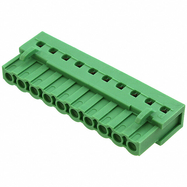
ICGOO电子元器件商城为您提供1912919由Phoenix Contact设计生产,在icgoo商城现货销售,并且可以通过原厂、代理商等渠道进行代购。 1912919价格参考。Phoenix Contact1912919封装/规格:接线座 - 接头,插头和插口, 9 位 端接块 插头,母插口 0.200"(5.08mm) 270° 自由悬挂。您可以下载1912919参考资料、Datasheet数据手册功能说明书,资料中有1912919 详细功能的应用电路图电压和使用方法及教程。
Phoenix Contact型号1912919属于接线座-接头/插头类电气连接器,广泛应用于工业自动化和电气控制系统中。该产品常用于PLC控制柜、配电箱、机械设备、工业生产线、测试设备及电力电子设备中,实现安全可靠的电源和信号传输。其紧凑设计和高防护等级适用于空间受限但要求稳定连接的场合,如工厂自动化、机械制造、能源管理及楼宇控制系统。
| 参数 | 数值 |
| 产品目录 | |
| 描述 | TERM BLOCK PLUG 9POS 5.08MM可插拔接线端子 MVSTBW 2.5 HC/ 9-ST- |
| 产品分类 | |
| 品牌 | Phoenix Contact |
| 产品手册 | http://www.phoenixcontact.com/us/products/1912919/pdf |
| 产品图片 | |
| rohs | 符合RoHS无铅 / 符合限制有害物质指令(RoHS)规范要求 |
| 产品系列 | 可插拔接线端子,Phoenix Contact 1912919COMBICON MVSTBW |
| mouser_ship_limit | 该产品可能需要其他文档才能发货到中国。 |
| 数据手册 | |
| 产品型号 | 1912919 |
| 产品种类 | 可插拔接线端子 |
| 位置数量 | 9 |
| 其它名称 | MVSTBW 2.5 HC/ 9-ST-5.08 |
| 包装 | 散装 |
| 单位重量 | 18.520 g |
| 可燃性等级 | UL 94 V-0 |
| 商标 | Phoenix Contact |
| 商标名 | COMBICON Power |
| 外壳材料 | Polyamide (PA) |
| 安装类型 | 自由悬挂 |
| 工厂包装数量 | 50 |
| 插线入口 | 270° |
| 标准包装 | 50 |
| 每级针脚数 | 9 |
| 特性 | 固定锁(非导线侧) |
| 电压 | 300V |
| 电压额定值 | 300 V |
| 电流 | 16A |
| 电流额定值 | 10 A |
| 端子块类型 | 插头,母插口 |
| 端接 | 螺钉 |
| 端接类型 | Through Hole |
| 级别数 | 1 |
| 线规 | 12-30 AWG |
| 线规最大值 | 12 |
| 线规最小值 | 30 |
| 线规量程 | 30-12 |
| 节距 | 5.08 mm |
| 配套产品 | /product-detail/zh/1924376/1924376-ND/2511621/product-detail/zh/1923937/1923937-ND/2511396 |
| 针座方向 | - |
| 针脚数 | 9 |
| 间距 | 0.200"(5.08mm) |
| 零件号别名 | MVSTBW_2,5_HC/_9-ST-5,08 MVSTBW25HC9ST508 |
| 颜色 | Green |


- 商务部:美国ITC正式对集成电路等产品启动337调查
- 曝三星4nm工艺存在良率问题 高通将骁龙8 Gen1或转产台积电
- 太阳诱电将投资9.5亿元在常州建新厂生产MLCC 预计2023年完工
- 英特尔发布欧洲新工厂建设计划 深化IDM 2.0 战略
- 台积电先进制程称霸业界 有大客户加持明年业绩稳了
- 达到5530亿美元!SIA预计今年全球半导体销售额将创下新高
- 英特尔拟将自动驾驶子公司Mobileye上市 估值或超500亿美元
- 三星加码芯片和SET,合并消费电子和移动部门,撤换高东真等 CEO
- 三星电子宣布重大人事变动 还合并消费电子和移动部门
- 海关总署:前11个月进口集成电路产品价值2.52万亿元 增长14.8%


PDF Datasheet 数据手册内容提取
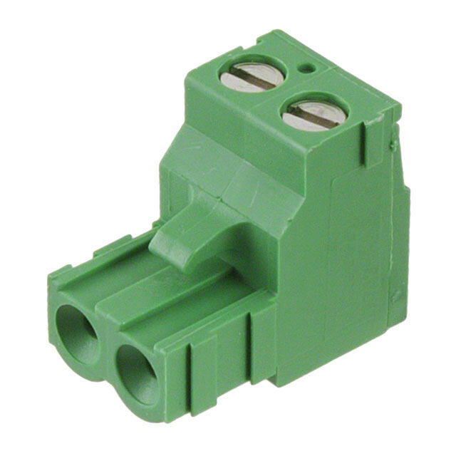
COMBICON Plugs and Headers as a „high current“ (HC) Version for Currents up to 16 A, 5.0 or 5.08 mm Pitch Tuning for the MSTB classic The proven COMBICON MSTB plug connector is now available as a "high current" (HC) version for currents up to 16 A. On top of the familiar MSTB features, a dou- ble steel spring guarantees extra safety for higher power transmission. The HC family is available with 2 to 12 positions and in pitches of 5.0 and 5.08 mm. Only the MSTB 2,5 HC headers provided are allowed to be used for carrying the higher current load of 16 A. Headquarters: © Phoenix Contact GmbH & Co. KG• Flachsmarktstraße 8 • 32825 Blomberg • Germany Phone +49-(0) 52 35-3-00 • Fax +49-(0) 52 35-3-4 12 0 • http://www.phoenixcontact.com PHOENIX CONTACT page 1 of 13
MSTB 2,5 HC/…-ST(-5,08) 5.0 or 5.08 mm Pitch The designation "HC" is printed in red to provide clear identification of "high current" plugs and headers. Only the MSTB 2,5 HC headers provided are allowed to be used for carrying the higher current load of 16 A. Note: Only actuate COMBICON plug connectors when under no load condition. If for operating reasons small loads must be switched, experimental values are available upon request. Dim. Description No. of pos. a Type Order No. Pcs./Pkt. [mm] COMBICON HC plugs, 5.0 mm pitch color: green 2 5 MSTB 2,5 HC/2-ST 19 11 85 5 50 3 10 MSTB 2,5 HC/3-ST 19 11 86 8 4 15 MSTB 2,5 HC/4-ST 19 11 87 1 5 20 MSTB 2,5 HC/5-ST 19 11 88 4 6 25 MSTB 2,5 HC/6-ST 19 11 89 7 7 30 MSTB 2,5 HC/7-ST 19 11 90 7 8 35 MSTB 2,5 HC/8-ST 19 11 91 0 9 40 MSTB 2,5 HC/9-ST 19 11 92 3 10 45 MSTB 2,5 HC/10-ST 19 11 93 6 11 50 MSTB 2,5 HC/11-ST 19 11 94 9 12 55 MSTB 2,5 HC/12-ST 19 11 95 2 COMBICON HC plugs, 5.08 mm pitch color: green 2 5.08 MSTB 2,5 HC/2-ST-5,08 19 11 96 5 50 3 10.16 MSTB 2,5 HC/3-ST-5,08 19 11 97 8 4 15.24 MSTB 2,5 HC/4-ST-5,08 19 11 98 1 5 20.32 MSTB 2,5 HC/5-ST-5,08 19 11 99 4 6 25.40 MSTB 2,5 HC/6-ST-5,08 19 12 00 3 7 30.48 MSTB 2,5 HC/7-ST-5,08 19 12 01 6 8 35.56 MSTB 2,5 HC/8-ST-5,08 19 12 02 9 9 40.64 MSTB 2,5 HC/9-ST-5,08 19 12 03 2 10 45.72 MSTB 2,5 HC/10-ST-5,08 19 12 04 5 11 50.80 MSTB 2,5 HC/11-ST-5,08 19 12 05 8 12 55.88 MSTB 2,5 HC/12-ST-5,08 19 12 06 1 (1) Coding profile, is inserted into the groove on the plug, CP-MSTB 17 34 63 4 100 red insulating material (2) Marker card, with 12 pcs. 10-section marker strips, white, SK 5/3,8 or SK 5,08/3,8 self-adhesive, for 120 terminal blocks (see COMBICON catalog) Technical data Dimensions see description on page 13 Pitch [mm] 5 / 5.08 Hole diameter [mm| – Pin dimensions [mm]x[mm] – Technical data in accordance with IEC/ DIN VDE Insulating material group – I Surge voltage category / contamination class –/– III / 3 III / 2 II / 2 Rated voltage [V] 250 320 630 Rated surge voltage [kV] 4 4 4 Nominal current / cross section [A]/[mm2] 16 / 2.5 Maximum load current / cross section [A]/[mm2] 16 / 2.5 Capacity connection Solid / stranded / conductor sizes [mm2]/[mm2]/AWG 0.2 - 2.5 / 0.2 - 2.5 / 24 - 12 Stranded with ferrule without / with plastic sleeve [mm2] 0.25 - 2.5 / 0.25 - 2.5 Multiple connection (2 conductors with same cross section) Solid / stranded [mm2] 0.2 - 1 / 0.2 - 1.5 Stranded with ferrule with plastic sleeve [mm2] 0.25 - 1 Stranded with TWIN ferrule with plastic sleeve [mm2] 0.5 - 1.5 Stripping length [mm] 7 Internal cylindrical gauge (IEC 60 947-1) A 3 Thread M 3 Torque [Nm] 0.5 - 0.6 Insulating material PA Inflammability class in acc. with UL 94 V0 PHOENIX CONTACT page 2 of 13
MSTB 2,5 HC/…-STF(-5,08) with Srew Flange 5.0 or 5.08 mm Pitch The designation "HC" is printed in red to provide clear identification of "high current" plugs and headers. Only the MSTB 2,5 HC headers provided are allowed to be used for carrying the higher current load of 16 A. Note: Only actuate COMBICON plug connectors when under no load condition. If for operating reasons small loads must be switched, experimental values are available upon request. Dim. Description No. of pos. a Type Order No. Pcs./Pkt. [mm] COMBICON HC plugs, 5.0 mm pitch, with screw flange, color: green 2 5 MSTB 2,5 HC/2-STF 19 12 07 4 50 3 10 MSTB 2,5 HC/3-STF 19 12 08 7 4 15 MSTB 2,5 HC/4-STF 19 12 09 0 5 20 MSTB 2,5 HC/5-STF 19 12 10 0 6 25 MSTB 2,5 HC/6-STF 19 12 11 3 7 30 MSTB 2,5 HC/7-STF 19 12 12 6 8 35 MSTB 2,5 HC/8-STF 19 12 13 9 9 40 MSTB 2,5 HC/9-STF 19 12 14 2 10 45 MSTB 2,5 HC/10-STF 19 12 15 5 11 50 MSTB 2,5 HC/11-STF 19 12 16 8 12 55 MSTB 2,5 HC/12-STF 19 12 17 1 COMBICON HC plugs, 5.08 mm pitch, with screw flange, color: green 2 5.08 MSTB 2,5 HC/2-STF-5,08 19 12 18 4 50 3 10.16 MSTB 2,5 HC/3-STF-5,08 19 12 19 7 4 15.24 MSTB 2,5 HC/4-STF-5,08 19 12 20 7 5 20.32 MSTB 2,5 HC/5-STF-5,08 19 12 21 0 6 25.40 MSTB 2,5 HC/6-STF-5,08 19 12 22 3 7 30.48 MSTB 2,5 HC/7-STF-5,08 19 12 23 6 8 35.56 MSTB 2,5 HC/8-STF-5,08 19 12 24 9 9 40.64 MSTB 2,5 HC/9-STF-5,08 19 12 25 2 10 45.72 MSTB 2,5 HC/10-STF-5,08 19 12 26 5 11 50.80 MSTB 2,5 HC/11-STF-5,08 19 12 27 8 12 55.88 MSTB 2,5 HC/12-STF-5,08 19 12 28 1 (1) Coding profile, is inserted into the groove on the plug, CP-MSTB 17 34 63 4 100 red insulating material (2) Marker card, with 12 pcs. 10-section marker strips, white, SK 5/3,8 or SK 5,08/3,8 self-adhesive, for 120 terminal blocks (see COMBICON catalog) Technical data Dimensions see description on page 13 Pitch [mm] 5 / 5.08 Hole diameter [mm| – Pin dimensions [mm]x[mm] – Technical data in accordance with IEC/ DIN VDE Insulating material group – I Surge voltage category / contamination class –/– III / 3 III / 2 II / 2 Rated voltage [V] 250 320 630 Rated surge voltage [kV] 4 4 4 Nominal current / cross section [A]/[mm2] 16 / 2.5 Maximum load current / cross section [A]/[mm2] 16 / 2.5 Capacity connection Solid / stranded / conductor sizes [mm2]/[mm2]/AWG 0.2 - 2.5 / 0.2 - 2.5 / 24 - 12 Stranded with ferrule without / with plastic sleeve [mm2] 0.25 - 2.5 / 0.25 - 2.5 Multiple connection (2 conductors with same cross section) Solid / stranded [mm2] 0.2 - 1 / 0.2 - 1.5 Stranded with ferrule with plastic sleeve [mm2] 0.25 - 1 Stranded with TWIN ferrule with plastic sleeve [mm2] 0.5 - 1.5 Stripping length [mm] 7 Internal cylindrical gauge (IEC 60 947-1) A 3 Thread M 3 Torque [Nm] 0.5 - 0.6 Insulating material PA Inflammability class in acc. with UL 94 V0 PHOENIX CONTACT page 3 of 13
MSTBT 2,5 HC/…-ST 5.0 mm Pitch The designation "HC" is printed in red to provide clear identification of "high current" plugs and headers. Only the MSTB 2,5 HC headers provided are allowed to be used for carrying the higher current load of 16 A. Note: Only actuate COMBICON plug connectors when under no load condition. If for operating reasons small loads must be switched, experimental values are available upon request. Dim. Description No. of pos. a Type Order No. Pcs./Pkt. [mm] COMBICON HC plugs, 5.0 mm pitch, color: green 2 5 MSTBT 2,5 HC/2-ST 19 26 35 8 50 3 10 MSTBT 2,5 HC/3-ST 19 26 24 8 4 15 MSTBT 2,5 HC/4-ST 19 26 25 1 5 20 MSTBT 2,5 HC/5-ST 19 26 26 4 6 25 MSTBT 2,5 HC/6-ST 19 26 27 7 7 30 MSTBT 2,5 HC/7-ST 19 26 28 0 8 35 MSTBT 2,5 HC/8-ST 19 26 29 3 9 40 MSTBT 2,5 HC/9-ST 19 26 30 3 10 45 MSTBT 2,5 HC/10-ST 19 26 31 6 11 50 MSTBT 2,5 HC/11-ST 19 26 32 9 12 55 MSTBT 2,5 HC/12-ST 19 26 33 2 (1) Coding profile, is inserted into the groove on the plug, CP-MSTB 17 34 63 4 100 red insulating material (2) Marker card, with 12 pcs. 10-section marker strips, white, SK 5/3,8 self-adhesive, for 120 terminal blocks (see COMBICON catalog) Technical data Dimensions see description on page 13 Pitch [mm] 5 Hole diameter [mm| – Pin dimensions [mm]x[mm] – Technical data in accordance with IEC/ DIN VDE Insulating material group – I Surge voltage category / contamination class –/– III / 3 III / 2 II / 2 Rated voltage [V] 250 320 630 Rated surge voltage [kV] 4 4 4 Nominal current / cross section [A]/[mm2] 16 / 2.5 Maximum load current / cross section [A]/[mm2] 16 / 2.5 Capacity connection Solid / stranded / conductor sizes [mm2]/[mm2]/AWG 0.2 - 2.5 / 0.2 - 2.5 / 24 - 12 Stranded with ferrule without / with plastic sleeve [mm2] 0.25 - 2.5 / 0.25 - 2.5 Multiple connection (2 conductors with same cross section) Solid / stranded [mm2] 0.2 - 1 / 0.2 - 1.5 Stranded with ferrule with plastic sleeve [mm2] 0.25 - 1 Stranded with TWIN ferrule with plastic sleeve [mm2] 0.5 - 1.5 Stripping length [mm] 7 Internal cylindrical gauge (IEC 60 947-1) A 3 Thread M 3 Torque [Nm] 0.5 - 0.6 Insulating material PA Inflammability class in acc. with UL 94 V0 18,2 a+5 51 8,3 2,5 5 a PHOENIX CONTACT page 4 of 13
MVSTBR 2,5 HC/…-ST(-5,08) Vertical Plugs 5.0 or 5.08 mm Pitch The designation "HC" is printed in red to provide clear identification of "high current" plugs and headers. Only the MSTB 2,5 HC headers provided are allowed to be used for carrying the higher current load of 16 A. Note: Only actuate COMBICON plug connectors when under no load condition. If for operating reasons small loads must be switched, experimental values are available upon request. Dim. Description No. of pos. a Type Order No. Pcs./Pkt. [mm] COMBICON HC plugs, 5.0 mm pitch, plug-in direction vertical to the conductor axis, 2 5 MVSTBR 2,5 HC/2-ST 19 12 29 4 50 connection point facing the smooth wall (R) 3 10 MVSTBR 2,5 HC/3-ST 19 12 30 4 of the header, color: green 4 15 MVSTBR 2,5 HC/4-ST 19 12 31 7 5 20 MVSTBR 2,5 HC/5-ST 19 12 32 0 6 25 MVSTBR 2,5 HC/6-ST 19 12 33 3 7 30 MVSTBR 2,5 HC/7-ST 19 12 34 6 8 35 MVSTBR 2,5 HC/8-ST 19 12 35 9 9 40 MVSTBR 2,5 HC/9-ST 19 12 36 2 10 45 MVSTBR 2,5 HC/10-ST 19 12 37 5 11 50 MVSTBR 2,5 HC/11-ST 19 12 38 8 12 55 MVSTBR 2,5 HC/12-ST 19 12 39 1 COMBICON HC plugs, 5.08 mm pitch, plug-in direction vertical to the conductor axis, 2 5.08 MVSTBR 2,5 HC/2-ST-5,08 19 12 40 1 50 connection point facing the smooth wall (R) 3 10.16 MVSTBR 2,5 HC/3-ST-5,08 19 12 41 4 of the header, color: green 4 15.24 MVSTBR 2,5 HC/4-ST-5,08 19 12 42 7 5 20.32 MVSTBR 2,5 HC/5-ST-5,08 19 12 43 0 6 25.40 MVSTBR 2,5 HC/6-ST-5,08 19 12 44 3 7 30.48 MVSTBR 2,5 HC/7-ST-5,08 19 12 45 6 8 35.56 MVSTBR 2,5 HC/8-ST-5,08 19 12 46 9 9 40.64 MVSTBR 2,5 HC/9-ST-5,08 19 12 47 2 10 45.72 MVSTBR 2,5 HC/10-ST-5,08 19 12 48 5 11 50.80 MVSTBR 2,5 HC/11-ST-5,08 19 12 49 8 12 55.88 MVSTBR 2,5 HC/12-ST-5,08 19 12 50 8 (1) Coding profile, is inserted into the groove on the plug, CP-MSTB 17 34 63 4 100 red insulating material (2) Marker card, with 12 pcs. 10-section marker strips, white, SK 5/3,8 or SK 5,08/3,8 self-adhesive, for 120 terminal blocks (see COMBICON catalog) Technical data Dimensions see description on page 13 Pitch [mm] 5 / 5.08 Hole diameter [mm| – Pin dimensions [mm]x[mm] – Technical data in accordance with IEC/ DIN VDE Insulating material group – I Surge voltage category / contamination class –/– III / 3 III / 2 II / 2 Rated voltage [V] 250 320 630 Rated surge voltage [kV] 4 4 4 Nominal current / cross section [A]/[mm2] 16 / 2.5 Maximum load current / cross section [A]/[mm2] 16 / 2.5 Capacity connection Solid / stranded / conductor sizes [mm2]/[mm2]/AWG 0.2 - 2.5 / 0.2 - 2.5 / 24 - 12 Stranded with ferrule without / with plastic sleeve [mm2] 0.25 - 2.5 / 0.25 - 2.5 Multiple connection (2 conductors with same cross section) Solid / stranded [mm2] 0.2 - 1 / 0.2 - 1.5 Stranded with ferrule with plastic sleeve [mm2] 0.25 - 1 Stranded with TWIN ferrule with plastic sleeve [mm2] 0.5 - 1.5 Stripping length [mm] 7 Internal cylindrical gauge (IEC 60 947-1) A 3 Thread M 3 Torque [Nm] 0.5 - 0.6 Insulating material PA Inflammability class in acc. with UL 94 V0 PHOENIX CONTACT page 5 of 13
MVSTBR 2,5 HC/…-STF(-5,08) Vertical Plugs with Screw Flange 5.0 or 5.08 mm Pitch The designation "HC" is printed in red to provide clear identification of "high current" plugs and headers. Only the MSTB 2,5 HC headers provided are allowed to be used for carrying the higher current load of 16 A. Note: Only actuate COMBICON plug connectors when under no load condition. If for operating reasons small loads must be switched, experimental values are available upon request. Dim. Description No. of pos. a Type Order No. Pcs./Pkt. [mm] COMBICON HC plugs, 5.0 mm pitch, with screw flange, color: green, 2 5 MVSTBR 2,5 HC/2-STF 19 12 51 1 50 connection point facing the smooth wall (R) 3 10 MVSTBR 2,5 HC/3-STF 19 12 52 4 of the header 4 15 MVSTBR 2,5 HC/4-STF 19 12 53 7 5 20 MVSTBR 2,5 HC/5-STF 19 12 54 0 6 25 MVSTBR 2,5 HC/6-STF 19 12 55 3 7 30 MVSTBR 2,5 HC/7-STF 19 12 56 6 8 35 MVSTBR 2,5 HC/8-STF 19 12 57 9 9 40 MVSTBR 2,5 HC/9-STF 19 12 58 2 10 45 MVSTBR 2,5 HC/10-STF 19 12 59 5 11 50 MVSTBR 2,5 HC/11-STF 19 12 60 5 12 55 MVSTBR 2,5 HC/12-STF 19 12 61 8 COMBICON HC plugs, 5.08 mm pitch, with screw flange, color: green, 2 5.08 MVSTBR 2,5 HC/2-STF-5,08 19 12 62 1 50 connection point facing the smooth wall (R) 3 10.16 MVSTBR 2,5 HC/3-STF-5,08 19 12 63 4 of the header 4 15.24 MVSTBR 2,5 HC/4-STF-5,08 19 12 64 7 5 20.32 MVSTBR 2,5 HC/5-STF-5,08 19 12 65 0 6 25.40 MVSTBR 2,5 HC/6-STF-5,08 19 12 66 3 7 30.48 MVSTBR 2,5 HC/7-STF-5,08 19 12 67 6 8 35.56 MVSTBR 2,5 HC/8-STF-5,08 19 12 68 9 9 40.64 MVSTBR 2,5 HC/9-STF-5,08 19 12 69 2 10 45.72 MVSTBR 2,5 HC/10-STF-5,08 19 12 70 2 11 50.80 MVSTBR 2,5 HC/11-STF-5,08 19 12 71 5 12 55.88 MVSTBR 2,5 HC/12-STF-5,08 19 12 72 8 (1) Coding profile, is inserted into the groove on the plug, CP-MSTB 17 34 63 4 100 red insulating material (2) Marker card, with 12 pcs. 10-section marker strips, white, SK 5/3,8 or SK 5,08/3,8 self-adhesive, for 120 terminal blocks (see COMBICON catalog) Technical data Dimensions see description page 13 Pitch [mm] 5 / 5.08 Hole diameter [mm| – Pin dimensions [mm]x[mm] – Technical data in accordance with IEC/ DIN VDE Insulating material group – I Surge voltage category / contamination class –/– III / 3 III / 2 II / 2 Rated voltage [V] 250 320 630 Rated surge voltage [kV] 4 4 4 Nominal current / cross section [A]/[mm2] 16 / 2.5 Maximum load current / cross section [A]/[mm2] 16 / 2.5 Capacity connection Solid / stranded / conductor sizes [mm2]/[mm2]/AWG 0.2 - 2.5 / 0.2 - 2.5 / 24 - 12 Stranded with ferrule without / with plastic sleeve [mm] 0.25 - 2.5 / 0.25 - 2.5 Multiple connection (2 conductors with same cross section) Solid / stranded [mm2] 0.2 - 1 / 0.2 - 1.5 Stranded with ferrule with plastic sleeve [mm2] 0.25 - 1 Stranded with TWIN ferrule with plastic sleeve [mm2] 0.5 - 1.5 Stripping length [mm] 7 Internal cylindrical gauge (IEC 60 947-1) A 3 Thread M 3 Torque [Nm] 0.5 - 0.6 Insulating material PA Inflammability class in acc. with UL 94 V0 PHOENIX CONTACT page 6 of 13
MVSTBW 2,5 HC/…-ST(-5,08) Vertical Plugs 5.0 or 5.08 mm Pitch The designation "HC" is printed in red to provide clear identification of "high current" plugs and headers. Only the MSTB 2,5 HC headers provided are allowed to be used for carrying the higher current load of 16 A. Note: Only actuate COMBICON plug connectors when under no load condition. If for operating reasons small loads must be switched, experimental values are available upon request. Dim. Description No. of pos. a Type Order No. Pcs./Pkt. [mm] COMBICON HC plugs, 5.0 mm pitch, plug-in direction vertical to the conductor axis, 2 5 MVSTBW 2,5 HC/2-ST 19 12 73 1 50 connection point facing the rippled wall (W) 3 10 MVSTBW 2,5 HC/3-ST 19 12 74 4 of the header, color: green 4 15 MVSTBW 2,5 HC/4-ST 19 12 75 7 5 20 MVSTBW 2,5 HC/5-ST 19 12 76 0 6 25 MVSTBW 2,5 HC/6-ST 19 12 77 3 7 30 MVSTBW 2,5 HC/7-ST 19 12 78 6 8 35 MVSTBW 2,5 HC/8-ST 19 12 79 9 9 40 MVSTBW 2,5 HC/9-ST 19 12 80 9 10 45 MVSTBW 2,5 HC/10-ST 19 12 81 2 11 50 MVSTBW 2,5 HC/11-ST 19 12 82 5 12 55 MVSTBW 2,5 HC/12-ST 19 12 83 8 COMBICON HC plugs, 5.08 mm pitch, plug-in direction vertical to the conductor axis, 2 5.08 MVSTBW 2,5 HC/2-ST-5,08 19 12 84 1 50 connection point facing the rippled wall (W) 3 10.16 MVSTBW 2,5 HC/3-ST-5,08 19 12 85 4 of the header, color: green 4 15.24 MVSTBW 2,5 HC/4-ST-5,08 19 12 86 7 5 20.32 MVSTBW 2,5 HC/5-ST-5,08 19 12 87 0 6 25.40 MVSTBW 2,5 HC/6-ST-5,08 19 12 88 3 7 30.48 MVSTBW 2,5 HC/7-ST-5,08 19 12 89 6 8 35.56 MVSTBW 2,5 HC/8-ST-5,08 19 12 90 6 9 40.64 MVSTBW 2,5 HC/9-ST-5,08 19 12 91 9 10 45.72 MVSTBW 2,5 HC/10-ST-5,08 19 12 92 2 11 50.80 MVSTBW 2,5 HC/11-ST-5,08 19 12 93 5 12 55.88 MVSTBW 2,5 HC/12-ST-5,08 19 12 94 8 (1) Coding profile, is inserted into the groove on the plug, CP-MSTB 17 34 63 4 100 red insulating material (2) Marker card, with 12 pcs. 10-section marker strips, white, SK 5/3,8 or SK 5,08/3,8 self-adhesive, for 120 terminal blocks (see COMBICON catalog) Technical data Dimensions see description on page 13 Pitch [mm] 5 / 5.08 Hole diameter [mm| – Pin dimensions [mm]x[mm] – Technical data in accordance with IEC/ DIN VDE Insulating material group – I Surge voltage category / contamination class –/– III / 3 III / 2 II / 2 Rated voltage [V] 250 320 630 Rated surge voltage [kV] 4 4 4 Nominal current / cross section [A]/[mm2] 16 / 2.5 Maximum load current / cross section [A]/[mm2] 16 / 2.5 Capacity connection Solid / stranded / conductor sizes [mm2]/[mm2]/AWG 0.2 - 2.5 / 0.2 - 2.5 / 24 - 12 Stranded with ferrule without / with plastic sleeve [mm2] 0.25 - 2.5 / 0.25 - 2.5 Multiple connection (2 conductors with same cross section) Solid / stranded [mm2] 0.2 - 1 / 0.2 - 1.5 Stranded with ferrule with plastic sleeve [mm2] 0.25 - 1 Stranded with TWIN ferrule with plastic sleeve [mm2] 0.5 - 1.5 Stripping length [mm] 7 Internal cylindrical gauge (IEC 60 947-1) A 3 Thread M 3 Torque [Nm] 0.5 - 0.6 Insulating material PA Inflammability class in acc. with UL 94 V0 PHOENIX CONTACT page 7 of 13
MVSTBW 2,5 HC/…-STF(-5,08) Vertical Plugs with Screw Flange 5.0 or 5.08 mm Pitch The designation "HC" is printed in red to provide clear identification of "high current" plugs and headers. Only the MSTB 2,5 HC headers provided are allowed to be used for carrying the higher current load of 16 A. Note: Only actuate COMBICON plug connectors when under no load condition. If for operating reasons small loads must be switched, experimental values are available upon request. Dim. Description No. of pos. a Type Order No. Pcs./Pkt. [mm] COMBICON HC plugs, 5.0 mm pitch, with screw flange, color: green, 2 5 MVSTBW 2,5 HC/2-STF 19 12 95 1 50 connection point facing the rippled wall (W) 3 10 MVSTBW 2,5 HC/3-STF 19 12 96 4 of the header 4 15 MVSTBW 2,5 HC/4-STF 19 12 97 7 5 20 MVSTBW 2,5 HC/5-STF 19 12 98 0 6 25 MVSTBW 2,5 HC/6-STF 19 12 99 3 7 30 MVSTBW 2,5 HC/7-STF 19 13 00 2 8 35 MVSTBW 2,5 HC/8-STF 19 13 01 5 9 40 MVSTBW 2,5 HC/9-STF 19 13 02 8 10 45 MVSTBW 2,5 HC/10-STF 19 13 03 1 11 50 MVSTBW 2,5 HC/11-STF 19 13 04 4 12 55 MVSTBW 2,5 HC/12-STF 19 13 05 7 COMBICON HC plugs, 5.08 mm pitch, with screw flange, color: green, 2 5.08 MVSTBW 2,5 HC/2-STF-5,08 19 13 06 0 50 connection point facing the rippled wall (W) 3 10.16 MVSTBW 2,5 HC/3-STF-5,08 19 13 07 3 of the header 4 15.24 MVSTBW 2,5 HC/4-STF-5,08 19 13 08 6 5 20.32 MVSTBW 2,5 HC/5-STF-5,08 19 13 09 9 6 25.40 MVSTBW 2,5 HC/6-STF-5,08 19 13 10 9 7 30.48 MVSTBW 2,5 HC/7-STF-5,08 19 13 11 2 8 35.56 MVSTBW 2,5 HC/8-STF-5,08 19 13 12 5 9 40.64 MVSTBW 2,5 HC/9-STF-5,08 19 13 13 8 10 45.72 MVSTBW 2,5 HC/10-STF-5,08 19 13 14 1 11 50.80 MVSTBW 2,5 HC/11-STF-5,08 19 13 15 4 12 55.88 MVSTBW 2,5 HC/12-STF-5,08 19 13 16 7 (1) Coding profile, is inserted into the groove on the plug, CP-MSTB 17 34 63 4 100 red insulating material (2) Marker card, with 12 pcs. 10-section marker strips, white, SK 5/3,8 or SK 5,08/3,8 self-adhesive, for 120 terminal blocks (see COMBICON catalog) Technical data Dimensions see description on page 13 Pitch [mm] 5 / 5.08 Hole diameter [mm| – Pin dimensions [mm]x[mm] – Technical data in accordance with IEC/ DIN VDE Insulating material group – I Surge voltage category / contamination class –/– III / 3 III / 2 II / 2 Rated voltage [V] 250 320 630 Rated surge voltage [kV] 4 4 4 Nominal current / cross section [A]/[mm2] 16 / 2.5 Maximum load current / cross section [A]/[mm2] 16 / 2.5 Capacity connection Solid / stranded / conductor sizes [mm2]/[mm2]/AWG 0.2 - 2.5 / 0.2 - 2.5 / 24 - 12 Stranded with ferrule without / with plastic sleeve [mm2] 0.25 - 2.5 / 0.25 - 2.5 Multiple connection (2 conductors with same cross section) Solid / stranded [mm2] 0.2 - 1 / 0.2 - 1.5 Stranded with ferrule with plastic sleeve [mm2] 0.25 - 1 Stranded with TWIN ferrule with plastic sleeve [mm2] 0.5 - 1.5 Stripping length [mm] 7 Internal cylindrical gauge (IEC 60 947-1) A 3 Thread M 3 Torque [Nm] 0.5 - 0.6 Insulating material PA Inflammability class in acc. with UL 94 V0 PHOENIX CONTACT page 8 of 13
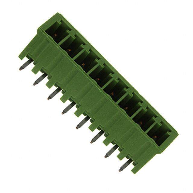
MSTBA 2,5 HC/…-G(-5,08) 5.0 or 5.08 mm Pitch The designation "HC" is printed in red to provide clear identification of "high current" plugs and headers. Only the MSTB 2,5 HC headers provided are allowed to be used for carrying the higher current load of 16 A. Note: Only actuate COMBICON plug connectors when under no load condition. If for operating reasons small loads must be switched, experimental values are available upon request. Dim. Description No. of pos. a Type Order No. Pcs./Pkt. [mm] COMBICON HC headers, 5.0 mm pitch, plug-in direction parallel to the p.c.b., 2 5 MSTBA 2,5 HC/2-G 19 23 75 9 50 color: green 3 10 MSTBA 2,5 HC/3-G 19 23 76 2 4 15 MSTBA 2,5 HC/4-G 19 23 77 5 5 20 MSTBA 2,5 HC/5-G 19 23 78 8 6 25 MSTBA 2,5 HC/6-G 19 23 79 1 7 30 MSTBA 2,5 HC/7-G 19 23 80 1 8 35 MSTBA 2,5 HC/8-G 19 23 81 4 9 40 MSTBA 2,5 HC/9-G 19 23 82 7 10 45 MSTBA 2,5 HC/10-G 19 23 83 0 11 50 MSTBA 2,5 HC/11-G 19 23 84 3 12 55 MSTBA 2,5 HC/12-G 19 23 85 6 COMBICON HC headers, 5.08 mm pitch, plug-in direction parallel to the p.c.b., 2 5.08 MSTBA 2,5 HC/2-G-5,08 19 23 86 9 50 color: green 3 10.16 MSTBA 2,5 HC/3-G-5,08 19 23 87 2 4 15.24 MSTBA 2,5 HC/4-G-5,08 19 23 88 5 5 20.32 MSTBA 2,5 HC/5-G-5,08 19 23 89 8 6 25.40 MSTBA 2,5 HC/6-G-5,08 19 23 90 8 7 30.48 MSTBA 2,5 HC/7-G-5,08 19 23 91 1 8 35.56 MSTBA 2,5 HC/8-G-5,08 19 23 92 4 9 40.64 MSTBA 2,5 HC/9-G-5,08 19 23 93 7 10 45.72 MSTBA 2,5 HC/10-G-5,08 19 23 94 0 11 50.80 MSTBA 2,5 HC/11-G-5,08 19 12 95 3 12 55.88 MSTBA 2,5 HC/12-G-5,08 19 12 96 6 (1) Coding section, inserted into the recess in the header, CR-MSTB 17 34 40 1 100 red insulating material (2) Marker card, with 12 pcs. 10-section marker strips, white, SK 5/3,8 or SK 5,08/3,8 self-adhesive, for 120 terminal blocks (see COMBICON catalog) Technical data Dimensions see description Pitch [mm] 5 / 5.08 Hole diameter [mm| 1.4 Pin dimensions [mm]x[mm] 1 x 1 Technical data in accordance with IEC/ DIN VDE Insulating material group – IIIa Surge voltage category / contamination class –/– III / 3 III / 2 II / 2 Rated voltage [V] 250 320 400 Rated surge voltage [kV] 4 4 4 Nominal current / cross section [A]/[mm2] 16 / – Maximum load current / cross section [A]/[mm2] 16 / – Insulating material PBT Inflammability class in acc. with UL 94 V0 22 a 12 5 3,5 a+7 (5,08) (3,54) (a+7,08) 2 41, 51 68, 53, 2 (3,35,45) (55,08) a PHOENIX CONTACT page 9 of 13
MSTBVA 2,5 HC/…-G(-5,08) 5.0 or 5.08 mm Pitch The designation "HC" is printed in red to provide clear identification of "high current" plugs and headers. Only the MSTB 2,5 HC headers provided are allowed to be used for carrying the higher current load of 16 A. Note: Only actuate COMBICON plug connectors when under no load condition. If for operating reasons small loads must be switched, experimental values are available upon request. Dim. Description No. of pos. a Type Order No. Pcs./Pkt. [mm] COMBICON HC headers vertical, 5.0 mm pitch, color: green, 2 5 MSTBVA 2,5 HC/2-G 19 24 19 8 50 plug-in direction vertical to the p.c.b. 3 10 MSTBVA 2,5 HC/3-G 19 24 20 8 4 15 MSTBVA 2,5 HC/4-G 19 24 21 1 5 20 MSTBVA 2,5 HC/5-G 19 24 22 4 6 25 MSTBVA 2,5 HC/6-G 19 24 23 7 7 30 MSTBVA 2,5 HC/7-G 19 24 24 0 8 35 MSTBVA 2,5 HC/8-G 19 24 25 3 9 40 MSTBVA 2,5 HC/9-G 19 24 26 6 10 45 MSTBVA 2,5 HC/10-G 19 24 27 9 11 50 MSTBVA 2,5 HC/11-G 19 24 28 2 12 55 MSTBVA 2,5 HC/12-G 19 24 29 5 COMBICON HC headers vertical, 5.08 mm pitch, color: green, 2 5.08 MSTBVA 2,5 HC/2-G-5,08 19 24 30 5 50 plug-in direction vertical to the p.c.b. 3 10.16 MSTBVA 2,5 HC/3-G-5,08 19 24 31 8 4 15.24 MSTBVA 2,5 HC/4-G-5,08 19 24 32 1 5 20.32 MSTBVA 2,5 HC/5-G-5,08 19 24 33 4 6 25.40 MSTBVA 2,5 HC/6-G-5,08 19 24 34 7 7 30.48 MSTBVA 2,5 HC/7-G-5,08 19 24 35 0 8 35.56 MSTBVA 2,5 HC/8-G-5,08 19 24 36 3 9 40.64 MSTBVA 2,5 HC/9-G-5,08 19 24 37 6 10 45.72 MSTBVA 2,5 HC/10-G-5,08 19 24 38 9 11 50.80 MSTBVA 2,5 HC/11-G-5,08 19 24 39 2 12 55.88 MSTBVA 2,5 HC/12-G-5,08 19 24 40 2 (1) Coding section, inserted into the recess in the header, CR-MSTB 17 34 40 1 100 red insulating material (2) Marker card, with 12 pcs. 10-section marker strips, white, SK 5/3,8 or SK 5,08/3,8 self-adhesive, for 120 terminal blocks (see COMBICON catalog) Technical data Dimensions see description Pitch [mm] 5 / 5.08 Hole diameter [mm| 1.4 Pin dimensions [mm]x[mm] 1 x 1 Technical data in accordance with IEC/ DIN VDE Insulating material group – I Surge voltage category / contamination class –/– III / 3 III / 2 II / 2 Rated voltage [V] 250 320 400 Rated surge voltage [kV] 4 4 4 Nominal current / cross section [A]/[mm2] 16 / – Maximum load current / cross section [A]/[mm2] 16 / – Insulating material PA Inflammability class in acc. with UL 94 V0 12,6 15 a 5 3,5 (5,08) (3,54) a+7 83, 41, 22 59,2 (a+7,08) 21 93, 3,8 3,5 5 8,6 (3,54) (5,08) a PHOENIX CONTACT page 10 of 13
MSTB 2,5 HC/…-GF(-5,08) with Screw Flange 5.0 or 5.08 mm Pitch The designation "HC" is printed in red to provide clear identification of "high current" plugs and headers. Only the MSTB 2,5 HC headers provided are allowed to be used for carrying the higher current load of 16 A. Note: Only actuate COMBICON plug connectors when under no load condition. If for operating reasons small loads must be switched, experimental values are available upon request. Dim. Description No. of pos. a Type Order No. Pcs./Pkt. [mm] COMBICON HC headers, 5.0 mm pitch, color: green, 2 5 MSTB 2,5 HC/2-GF 19 23 97 9 50 with threaded flange, 3 10 MSTB 2,5 HC/3-GF 19 23 98 2 plug-in direction parallel to the p.c.b. 4 15 MSTB 2,5 HC/4-GF 19 23 99 5 5 20 MSTB 2,5 HC/5-GF 19 24 00 4 6 25 MSTB 2,5 HC/6-GF 19 24 01 7 7 30 MSTB 2,5 HC/7-GF 19 24 02 0 8 35 MSTB 2,5 HC/8-GF 19 24 03 3 9 40 MSTB 2,5 HC/9-GF 19 24 04 6 10 45 MSTB 2,5 HC/10-GF 19 24 05 9 11 50 MSTB 2,5 HC/11-GF 19 24 06 2 12 55 MSTB 2,5 HC/12-GF 19 24 07 5 COMBICON HC headers, 5.08 mm pitch, color: green, 2 5.08 MSTB 2,5 HC/2-GF-5,08 19 24 08 8 50 with threaded flange 3 10.16 MSTB 2,5 HC/3-GF-5,08 19 24 09 1 plug-in direction parallel to the p.c.b. 4 15.24 MSTB 2,5 HC/4-GF-5,08 19 24 10 1 5 20.32 MSTB 2,5 HC/5-GF-5,08 19 24 11 4 6 25.40 MSTB 2,5 HC/6-GF-5,08 19 24 12 7 7 30.48 MSTB 2,5 HC/7-GF-5,08 19 24 13 0 8 35.56 MSTB 2,5 HC/8-GF-5,08 19 24 14 3 9 40.64 MSTB 2,5 HC/9-GF-5,08 19 24 15 6 10 45.72 MSTB 2,5 HC/10-GF-5,08 19 24 16 9 11 50.80 MSTB 2,5 HC/11-GF-5,08 19 24 17 2 12 55.88 MSTB 2,5 HC/12-GF-5,08 19 24 18 5 (1) Coding section, inserted into the recess in the header, CR-MSTB 17 34 40 1 100 red insulating material (2) Marker card, with 12 pcs. 10-section marker strips, white, SK 5/3,8 or SK 5,08/3,8 self-adhesive, for 120 terminal blocks (see COMBICON catalog) Technical data Dimensions see description Pitch [mm] 5 / 5.08 Hole diameter [mm| 1.4 Pin dimensions [mm]x[mm] 1 x 1 Technical data in accordance with IEC/ DIN VDE Insulating material group – IIIa Surge voltage category / contamination class –/– III / 3 III / 2 II / 2 Rated voltage [V] 250 320 400 Rated surge voltage [kV] 4 4 4 Nominal current / cross section [A]/[mm2] 16 / – Maximum load current / cross section [A]/[mm2] 16 / – Insulating material PBT Inflammability class in acc. with UL 94 V0 a 22 5 5 7,5 12 (5,08) (5,08) (7,62) a+15 2 41, (a+15,24) 52, 51 68, 53, 2,5 2 5 5 2,4 (5,08) (a5,08) 7,5 (7,62) PHOENIX CONTACT page 11 of 13
MSTBV 2,5 HC/…-GF(-5,08) with Screw Flange 5.0 or 5.08 mm Pitch The designation "HC" is printed in red to provide clear identification of "high current" plugs and headers. Only the MSTB 2,5 HC headers provided are allowed to be used for carrying the higher current load of 16 A. Note: Only actuate COMBICON plug connectors when under no load condition. If for operating reasons small loads must be switched, experimental values are available upon request. Dim. Description No. of pos. a Type Order No. Pcs./Pkt. [mm] COMBICON HC headers vertical, 5.0 mm pitch, color: green, 2 5 MSTBV 2,5 HC/2-GF 19 24 41 5 50 with threaded flange, 3 10 MSTBV 2,5 HC/3-GF 19 24 42 8 plug-in direction vertical to the p.c.b. 4 15 MSTBV 2,5 HC/4-GF 19 24 43 1 5 20 MSTBV 2,5 HC/5-GF 19 24 44 4 6 25 MSTBV 2,5 HC/6-GF 19 24 45 7 7 30 MSTBV 2,5 HC/7-GF 19 24 46 0 8 35 MSTBV 2,5 HC/8-GF 19 24 47 3 9 40 MSTBV 2,5 HC/9-GF 19 24 48 6 10 45 MSTBV 2,5 HC/10-GF 19 24 49 9 11 50 MSTBV 2,5 HC/11-GF 19 24 50 9 12 55 MSTBV 2,5 HC/12-GF 19 24 51 2 COMBICON HC headers vertical, 5.08 mm pitch, color: green, 2 5.08 MSTBV 2,5 HC/2-GF-5,08 19 24 52 5 50 with threaded flange 3 10.16 MSTBV 2,5 HC/3-GF-5,08 19 24 53 8 plug-in direction vertical to the p.c.b. 4 15.24 MSTBV 2,5 HC/4-GF-5,08 19 24 54 1 5 20.32 MSTBV 2,5 HC/5-GF-5,08 19 24 55 4 6 25.40 MSTBV 2,5 HC/6-GF-5,08 19 24 56 7 7 30.48 MSTBV 2,5 HC/7-GF-5,08 19 24 57 0 8 35.56 MSTBV 2,5 HC/8-GF-5,08 19 24 58 3 9 40.64 MSTBV 2,5 HC/9-GF-5,08 19 24 59 6 10 45.72 MSTBV 2,5 HC/10-GF-5,08 19 24 60 6 11 50.80 MSTBV 2,5 HC/11-GF-5,08 19 24 61 9 12 55.88 MSTBV 2,5 HC/12-GF-5,08 19 24 62 2 (1) Coding section, inserted into the recess in the header, CR-MSTB 17 34 40 1 100 red insulating material (2) Marker card, with 12 pcs. 10-section marker strips, white, SK 5/3,8 or SK 5,08/3,8 self-adhesive, for 120 terminal blocks (see COMBICON catalog) Technical data Dimensions see description Pitch [mm] 5 / 5.08 Hole diameter [mm| 1.4 Pin dimensions [mm]x[mm] 1 x 1 Technical data in accordance with IEC/ DIN VDE Insulating material group – I Surge voltage category / contamination class –/– III / 3 III / 2 II / 2 Rated voltage [V] 250 320 400 Rated surge voltage [kV] 4 4 4 Nominal current / cross section [A]/[mm2] 16 / – Maximum load current / cross section [A]/[mm2] 16 / – Insulating material PA Inflammability class in acc. with UL 94 V0 a 15 5 5 7,5 (5,08) (5,08) (7,62) a+15 83, 42, 22 (a+15,24) 21 1,4 93, 8,6 3,8(5,058) (5a5,08) (77,,562) PHOENIX CONTACT page 12 of 13
Descriptions 18,2 a+5 18,2 4,9 a+5 (a+5,08) (a+5,08) 51 51 8,3 2,5 5 8,3 5 5 (2,54) (5,08) (5,08) (5,08) a a MSTB 2,5 HC/…-ST(-5,08) MSTB 2,5 HC/…-STF(-5,08) 12,6 a+5 12,6 4,5 a+6 (a+5,08) (4,58) (a+6,08) 62 62 38, 38, 2,5 5 5 5 (2,54) (5,08) (5,08) (5,08) a a MVSTBR 2,5 HC/…-ST(-5.08) MVSTBR 2,5 HC/…-STF(-5,08) (a+a+5,508) 12,6 (a+a6+,608) (44,,558) 12,6 62 62 38, 38, 2,5 5 5 5 (2,54) (5,08) (5,08) (5,08) a a MVSTBW 2,5 HC/…-STF(-5,08) MVSTBW 2,5 HC/…-STF(-5,08) m o c ct. a nt o c x ni e o h p w. w w p:// htt 1 0 3- 5 5 9 9 0 5 R: N 1 T 0 3. 0 5. 1 T C A T N O C X NI E O H P (cid:211) PHOENIX CONTACT page 13 of 13