
 Datasheet下载
- 型号: 173D156X9020XWE3
- 制造商: Vishay
- 库位|库存: xxxx|xxxx
- 要求:
| 数量阶梯 | 香港交货 | 国内含税 |
| +xxxx | $xxxx | ¥xxxx |
查看当月历史价格
查看今年历史价格
173D156X9020XWE3产品简介:
ICGOO电子元器件商城为您提供173D156X9020XWE3由Vishay设计生产,在icgoo商城现货销售,并且可以通过原厂、代理商等渠道进行代购。 173D156X9020XWE3价格参考。Vishay173D156X9020XWE3封装/规格:钽电容器, 15µF Molded Tantalum Capacitors 20V Axial 。您可以下载173D156X9020XWE3参考资料、Datasheet数据手册功能说明书,资料中有173D156X9020XWE3 详细功能的应用电路图电压和使用方法及教程。
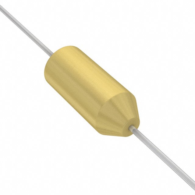
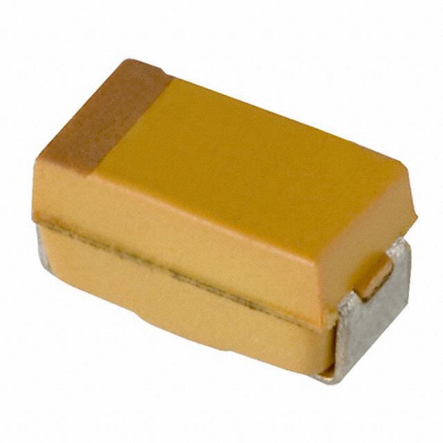
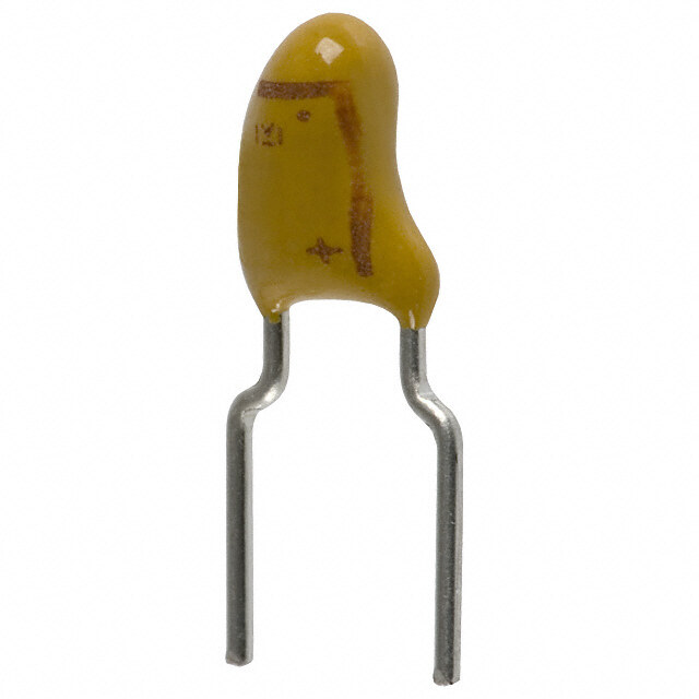
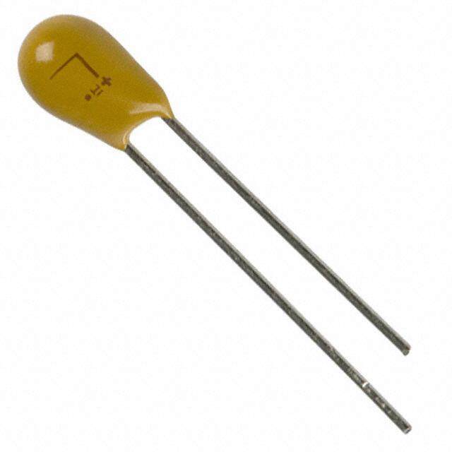
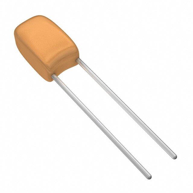
Vishay Sprague 173D156X9020XWE3 是一款高性能的军用级表面贴装钽电容器,属于MIL-PRF-55365标准系列,具有高可靠性与稳定性。该型号电容标称电容为15μF,额定电压为20V,采用EIA 7343封装尺寸,适用于对电气性能和长期可靠性要求极高的应用场景。

其主要应用领域包括航空航天、军事电子设备和卫星通信系统。在这些环境中,元器件需承受极端温度变化、强烈振动及长时间不间断运行,173D156X9020XWE3 凭借严格的筛选测试(如浪涌电流测试、高温寿命测试)和低漏电流特性,确保系统稳定工作。此外,它也广泛用于高端医疗设备,如植入式医疗器械和精密诊断仪器,因其具备良好的安全性和长期稳定性。

在工业控制领域,该电容器可用于高可靠性电源管理模块、DC-DC转换器和滤波电路中,提供稳定的储能和纹波抑制能力。同时,由于其符合RoHS环保要求并采用无铅端接,也适用于对环保和焊接工艺有严格要求的现代电子制造。

总之,173D156X9020XWE3 主要应用于高可靠、高安全性的关键电子系统,特别适合军工、航天、医疗和高端工业设备等对元器件品质要求严苛的场合。
| 参数 | 数值 |
| 产品目录 | |
| 描述 | CAP TANT 15UF 20V 10% AXIAL钽质电容器-固体铅 15uF 20volts 10% X case Axial |
| ESR(等效串联电阻) | - |
| 产品分类 | |
| 品牌 | Vishay / SpragueVishay Sprague |
| 产品手册 | |
| 产品图片 |
|
| rohs | 符合RoHS无铅 / 符合限制有害物质指令(RoHS)规范要求 |
| 产品系列 | 钽电容器,钽质电容器-固体铅,Vishay / Sprague 173D156X9020XWE3TANTALEX® 173D |
| 数据手册 | |
| 产品型号 | 173D156X9020XWE3173D156X9020XWE3 |
| 不同温度时的使用寿命 | - |
| 产品 | Tantalum Solid Molded |
| 产品目录绘图 |
|
| 产品目录页面 | |
| 产品种类 | 钽质电容器-固体铅 |
| 其它名称 | 718-1417-2 |
| 制造商尺寸代码 | X |
| 包装 | 带卷 (TR) |
| 商标 | Vishay / Sprague |
| 外壳直径 | 0.18 in |
| 外壳长度 | 0.42 in |
| 大小/尺寸 | 0.180" 直径 x 0.420" 长(4.57mm x 10.67mm) |
| 安装类型 | 通孔 |
| 容差 | ±10%10 % |
| 封装 | Reel |
| 封装/外壳 | 轴向 |
| 工作温度 | -55°C ~ 125°C |
| 工作温度范围 | - 55 C to + 85 C |
| 工厂包装数量 | 2500 |
| 引线间距 | - |
| 最大工作温度 | + 125 C |
| 最小工作温度 | - 55 C |
| 标准包装 | 2,500 |
| 特性 | 通用 |
| 特色产品 | http://www.digikey.com/cn/zh/ph/Vishay/TANTALEX.html |
| 电压-额定 | 20V |
| 电压额定值 | 20 V |
| 电压额定值DC | 20 V |
| 电容 | 15 uF15µF |
| 端接类型 | Axial |
| 类型 | 模制 |
| 系列 | 173D |
| 高度-安装(最大值) | - |


- 商务部:美国ITC正式对集成电路等产品启动337调查
- 曝三星4nm工艺存在良率问题 高通将骁龙8 Gen1或转产台积电
- 太阳诱电将投资9.5亿元在常州建新厂生产MLCC 预计2023年完工
- 英特尔发布欧洲新工厂建设计划 深化IDM 2.0 战略
- 台积电先进制程称霸业界 有大客户加持明年业绩稳了
- 达到5530亿美元!SIA预计今年全球半导体销售额将创下新高
- 英特尔拟将自动驾驶子公司Mobileye上市 估值或超500亿美元
- 三星加码芯片和SET,合并消费电子和移动部门,撤换高东真等 CEO
- 三星电子宣布重大人事变动 还合并消费电子和移动部门
- 海关总署:前11个月进口集成电路产品价值2.52万亿元 增长14.8%


PDF Datasheet 数据手册内容提取
173D www.vishay.com Vishay Sprague Solid-Electrolyte TANTALEX™ Capacitors, Axial-Leaded, Molded Case FEATURES • Axial through-hole terminations: tin / lead (SnPb), 100 % tin (RoHS-compliant) • Miniature axial-lead capacitors available in 5 sizes Available • Precision molded in gold colored, flam e retardant, thermosetting epoxy resin Available • Laser marked for improved legibility an d tapered end of case provides easy identification o f positive terminal • Standard orders are lead taped and reeled; orders under 500 are taped only • Material categorization: for definitions of complianc e please see www.vishay.com/doc?99912 Note * This datasheet provides information about parts that are RoHS-compliant and / or parts that are non RoHS-compliant. For LINKS TO ADDITIONAL RESOURCES example, parts with lead (Pb) terminations are not RoHS-compliant. 3DDD 333D Please see the information / tables in this datasheet for details APPLICATIONS 3D Models Designed for high performance automotive, industrial and commercial electronic equipment. PERFORMANCE CHARACTERISTICS Operating Temperature: -55 °C to +85 °C at +85 °C: leakage current shall not exceed 10 times the (to +125 °C with voltage derating) values listed in the Standard Ratings table. Capacitance Tolerance: at 120 Hz, +25 °C. at +125 °C: leakage shall not exceed 15 times the values ± 20 %, ± 10 % standard ± 5 % available as special listed in the Standard Ratings table. Capacitance Range: 0.10 μF to 330 μF. Life Test: capacitors shall withstand rated DC voltag e Voltage Rating: 2 V to 50 V . applied at +85 °C for 2000 h and for 1000 h applied DC DC at + 25 °C derated voltage. Dissipation Factor: at 120 Hz, +25 °C. Dissipation factor, as determined from the expression 2fRC, shall not exceed Following the life test: the values listed in the Standard Ratings table. 1. DCL shall not exceed 125 % of the initial requirements. DC Leakage Current (DCL Max.): 2. Dissipation factor shall meet the initial requirement. at +25 °C: leakage current shall not exceed the values listed 3. Change in capacitance shall not exceed ± 10 %. in the Standard Ratings table. ORDERING INFORMATION 173D 335 X9 006 U W E3 MODEL CAPACITANCE CAPACITANCE DC VOLTAGE RATING CASE PACKAGING RoHS- TOLERANCE AT +85 °C CODE COMPLIANT This is expressed in picofarads. X0 = ± 20 % This is expressed in volts. See W = tape E3 = 100 % The first two digits are the X9 = ± 10 % To complete the three-digit Ratings and reel tin termination significant figures. The third is *X5 = ± 5 % block, zeros precede the and Case Blank = ammo (RoHS- the number of zeros to follow. * Special order voltage rating. Codes pack compliant) table Blank = SnPb termination DIMENSIONS in inches [millimeters] 0.875 [22.23] L 0.875 [22.23] Min. Max. Min. (-) (+) D Tinned solid leads Tapered end identifies anode Max. CASE CODE D (MAX.) L (MAX.) LEAD DIAMETER U 0.095 [2.41] 0.260 [6.60] 0.020 [0.51] V 0.110 [2.79] 0.290 [7.37] 0.020 [0.51] W 0.180 [4.57] 0.345 [8.76] 0.020 [0.51] X 0.180 [4.57] 0.420 [10.67] 0.020 [0.51] Y 0.280 [7.11] 0.550 [13.97] 0.025 [0.64] Revision: 04-Aug-2020 1 Document Number: 40019 For technical questions, contact: tantalum@vishay.com THIS DOCUMENT IS SUBJECT TO CHANGE WITHOUT NOTICE. THE PRODUCTS DESCRIBED HEREIN AND THIS DOCUMENT ARE SUBJECT TO SPECIFIC DISCLAIMERS, SET FORTH AT www.vishay.com/doc?91000
173D www.vishay.com Vishay Sprague RATINGS AND CASE CODES μF 2 V 4 V 6 V 10 V 15 V 20 V 25 V 35 V 50 V 0.10 U U 0.12 U U 0.15 U U 0.18 U U 0.22 U U 0.27 U U 0.33 U V 0.39 U V 0.47 U U V 0.56 U V V 0.68 U V V 0.82 U V V 1.0 U U U V V 1.2 U V V W 1.5 U U V V W 1.8 U V V W W 2.2 U U U/V V W W 2.7 U V V V W X 3.3 U U V V V W X 3.9 U V V V W W X 4.7 U U V V V W W X 5.6 U V V V W W X Y 6.8 U U V V V W W X Y 8.2 U V V V W W W X Y 10 U V V V W W W X Y 12 V V V W W X X Y Y 15 V V V W W X X Y Y 18 V V W W X X Y Y Y 22 V V W W X X Y Y Y 27 V W W X X Y Y Y 33 V W W X X Y Y Y 39 W W X X Y Y Y Y 47 W W X X Y Y Y Y 56 W X X Y Y Y 68 W X X Y Y Y 82 Y Y Y Y 100 Y Y Y Y 120 Y Y Y 150 Y Y Y 180 Y Y 220 Y Y 270 Y 330 Y Revision: 04-Aug-2020 2 Document Number: 40019 For technical questions, contact: tantalum@vishay.com THIS DOCUMENT IS SUBJECT TO CHANGE WITHOUT NOTICE. THE PRODUCTS DESCRIBED HEREIN AND THIS DOCUMENT ARE SUBJECT TO SPECIFIC DISCLAIMERS, SET FORTH AT www.vishay.com/doc?91000
173D www.vishay.com Vishay Sprague MARKING PARAMETER EXAMPLE Product type 173D Polarity + Capacitance code, pF 156 Capacitance tolerance code K Voltage 25 V Date code 1209 Lead (Pb)-free indicator (1) L Vishay marking 2 Note (1) On big case sizes (W,X,Y) lead free indicator is printed after date code, for example 1209L. STANDARD RATINGS MAX. DCL MAX. DF CAPACITANCE CASE CODE PART NUMBER AT +25 °C AT +25 °C (μF) (μA) 120 Hz (%) 2 V AT +85 °C, SURGE = 2.5 V; 1.5 V AT +125 °C, SURGE = 1.8 V DC DC 6.8 U 173D685(1)002U(2)(3) 0.5 10 8.2 U 173D825(1)002U(2)(3) 0.5 10 10 U 173D106(1)002U(2)(3) 0.5 10 12 V 173D126(1)002V(2)(3) 0.5 10 15 V 173D156(1)002V(2)(3) 0.5 10 18 V 173D186(1)002V(2)(3) 0.5 10 22 V 173D226(1)002V(2)(3) 0.5 10 27 V 173D276(1)002V(2)(3) 0.5 10 33 V 173D336(1)002V(2)(3) 0.5 10 39 W 173D396(1)002W(2)(3) 0.6 10 47 W 173D476(1)002W(2)(3) 0.8 10 56 W 173D566(1)002W(2)(3) 0.9 10 68 W 173D686(1)002W(2)(3) 1.1 10 4 V AT +85 °C, SURGE = 5 V; 2.5 V AT +125 °C, SURGE = 3 V DC DC 4.7 U 173D475(1)004U(2)(3) 0.5 8 5.6 U 173D565(1)004U(2)(3) 0.5 8 6.8 U 173D685(1)004U(2)(3) 0.5 8 8.2 V 173D825(1)004V(2)(3) 0.5 8 10 V 173D106(1)004V(2)(3) 0.5 8 12 V 173D126(1)004V(2)(3) 0.5 8 15 V 173D156(1)004V(2)(3) 0.5 8 18 V 173D186(1)004V(2)(3) 0.6 8 22 V 173D226(1)004V(2)(3) 0.7 8 27 W 173D276(1)004W(2)(3) 0.9 8 33 W 173D336(1)004W(2)(3) 1.1 8 39 W 173D396(1)004W(2)(3) 1.2 8 47 W 173D476(1)004W(2)(3) 1.5 8 56 X 173D566(1)004X(2)(3) 1.5 8 68 X 173D686(1)004X(2)(3) 2.2 8 Note • Part number definition: (1) For 10 % tolerance specify “X9”; for 20 % specify “X0”; for 5 % specify “X5” (special order) (2) Packaging code: for reel 13" specify W, leave blank for ammo pack (3) Termination: for 100 % tin specify E3, for SnPb leave blank Revision: 04-Aug-2020 3 Document Number: 40019 For technical questions, contact: tantalum@vishay.com THIS DOCUMENT IS SUBJECT TO CHANGE WITHOUT NOTICE. THE PRODUCTS DESCRIBED HEREIN AND THIS DOCUMENT ARE SUBJECT TO SPECIFIC DISCLAIMERS, SET FORTH AT www.vishay.com/doc?91000
173D www.vishay.com Vishay Sprague STANDARD RATINGS MAX. DCL MAX. DF CAPACITANCE CASE CODE PART NUMBER AT +25 °C AT +25 °C (μF) (μA) 120 Hz (%) 6 V AT +85 °C, SURGE = 8 V; 4 V AT +125 °C, SURGE = 5 V DC DC 3.3 U 173D335(1)006U(2)(3) 0.5 4 3.9 U 173D395(1)006U(2)(3) 0.5 4 4.7 U 173D475(1)006U(2)(3) 0.5 4 5.6 V 173D565(1)006V(2)(3) 0.5 4 6.8 V 173D685(1)006V(2)(3) 0.5 6 8.2 V 173D825(1)006V(2)(3) 0.5 6 10 V 173D106(1)006V(2)(3) 0.5 6 12 V 173D126(1)006V(2)(3) 0.6 6 15 V 173D156(1)006V(2)(3) 0.7 6 18 W 173D186(1)006W(2)(3) 0.9 6 22 W 173D226(1)006W(2)(3) 1.1 6 27 W 173D276(1)006W(2)(3) 1.3 6 33 W 173D336(1)006W(2)(3) 1.5 6 39 X 173D396(1)006X(2)(3) 1.6 6 47 X 173D476(1)006X(2)(3) 2.3 6 56 X 173D566(1)006X(2)(3) 2.7 6 68 X 173D686(1)006X(2)(3) 3.3 6 82 Y 173D826(1)006Y(2)(3) 3.9 8 100 Y 173D107(1)006Y(2)(3) 4.8 8 120 Y 173D127(1)006Y(2)(3) 5.0 8 150 Y 173D157(1)006Y(2)(3) 5.0 8 180 Y 173D187(1)006Y(2)(3) 8.6 8 220 Y 173D227(1)006Y(2)(3) 10.0 8 270 Y 173D277(1)006Y(2)(3) 10.0 8 330 Y 173D337(1)006Y(2)(3) 10.0 8 10 V AT +85 °C, SURGE = 13 V; 7 V AT +125 °C, SURGE = 9 V DC DC 2.2 U 173D225(1)010U(2)(3) 0.5 4 2.7 U 173D275(1)010U(2)(3) 0.5 4 3.3 U 173D335(1)010U(2)(3) 0.5 4 3.9 V 173D395(1)010V(2)(3) 0.5 4 4.7 V 173D475(1)010V(2)(3) 0.5 4 5.6 V 173D565(1)010V(2)(3) 0.5 4 6.8 V 173D685(1)010V(2)(3) 0.5 6 8.2 V 173D825(1)010V(2)(3) 0.7 6 10 V 173D106(1)010V(2)(3) 0.8 6 12 W 173D126(1)010W(2)(3) 1.0 6 15 W 173D156(1)010W(2)(3) 1.2 6 18 W 173D186(1)010W(2)(3) 1.4 6 22 W 173D226(1)010W(2)(3) 1.5 6 27 X 173D276(1)010X(2)(3) 2.2 6 33 X 173D336(1)010X(2)(3) 2.6 6 39 X 173D396(1)010X(2)(3) 3.1 6 47 X 173D476(1)010X(2)(3) 3.8 6 56 Y 173D566(1)010Y(2)(3) 4.4 6 68 Y 173D686(1)010Y(2)(3) 5.0 6 82 Y 173D826(1)010Y(2)(3) 5.0 8 100 Y 173D107(1)010Y(2)(3) 8.0 8 Note • Part number definition: (1) For 10 % tolerance specify “X9”; for 20 % specify “X0”; for 5 % specify “X5” (special order) (2) Packaging code: for reel 13" specify W, leave blank for ammo pack (3) Termination: for 100 % tin specify E3, for SnPb leave blank Revision: 04-Aug-2020 4 Document Number: 40019 For technical questions, contact: tantalum@vishay.com THIS DOCUMENT IS SUBJECT TO CHANGE WITHOUT NOTICE. THE PRODUCTS DESCRIBED HEREIN AND THIS DOCUMENT ARE SUBJECT TO SPECIFIC DISCLAIMERS, SET FORTH AT www.vishay.com/doc?91000
173D www.vishay.com Vishay Sprague STANDARD RATINGS MAX. DCL MAX. DF CAPACITANCE CASE CODE PART NUMBER AT +25 °C AT +25 °C (μF) (μA) 120 Hz (%) 10 V AT +85 °C, SURGE = 13 V; 7 V AT +125 °C, SURGE = 9 V DC DC 120 Y 173D127(1)010Y(2)(3) 9.6 8 150 Y 173D157(1)010Y(2)(3) 10.0 8 180 Y 173D187(1)010Y(2)(3) 10.0 8 220 Y 173D227(1)010Y(2)(3) 10.0 8 15 V AT +85 °C, SURGE = 20 V; 10 V AT +125 °C, SURGE = 12 V DC DC 1.0 U 173D105(1)015U(2)(3) 0.5 4 1.5 U 173D155(1)015U(2)(3) 0.5 4 1.8 U 173D185(1)015U(2)(3) 0.5 4 2.2 U 173D225(1)015U(2)(3) 0.5 4 2.7 V 173D275(1)015V(2)(3) 0.5 4 3.3 V 173D335(1)015V(2)(3) 0.5 4 3.9 V 173D395(1)015V(2)(3) 0.5 4 4.7 V 173D475(1)015V(2)(3) 0.6 4 5.6 V 173D565(1)015V(2)(3) 0.7 4 6.8 V 173D685(1)015V(2)(3) 0.8 6 8.2 W 173D825(1)015W(2)(3) 1.0 6 10 W 173D106(1)015W(2)(3) 1.2 6 12 W 173D126(1)015W(2)(3) 1.4 6 15 W 173D156(1)015W(2)(3) 1.5 6 18 X 173D186(1)015X(2)(3) 2.2 6 22 X 173D226(1)015X(2)(3) 2.6 6 27 X 173D276(1)015X(2)(3) 3.2 6 33 X 173D336(1)015X(2)(3) 4.0 6 39 Y 173D396(1)015Y(2)(3) 4.7 6 47 Y 173D476(1)015Y(2)(3) 5.0 6 56 Y 173D566(1)015Y(2)(3) 6.7 6 68 Y 173D686(1)015Y(2)(3) 8.2 6 82 Y 173D826(1)015Y(2)(3) 9.8 8 100 Y 173D107(1)015Y(2)(3) 10.0 8 120 Y 173D127(1)015Y(2)(3) 10.0 8 150 Y 173D157(1)015Y(2)(3) 10.0 8 20 V AT +85 °C, SURGE = 26 V; 13 V AT +125 °C, SURGE = 16 V DC DC 1.0 U 173D105(1)020U(2)(3) 0.5 4 1.2 U 173D125(1)020U(2)(3) 0.5 4 1.5 U 173D155(1)020U(2)(3) 0.5 4 1.8 V 173D185(1)020V(2)(3) 0.5 4 2.2 U 173D225(1)020U(2)(3) 0.5 4 2.2 V 173D225(1)020V(2)(3) 0.5 4 2.7 V 173D275(1)020V(2)(3) 0.5 4 3.3 V 173D335(1)020V(2)(3) 0.5 4 3.9 V 173D395(1)020V(2)(3) 0.6 4 4.7 V 173D475(1)020V(2)(3) 0.8 4 5.6 W 173D565(1)020W(2)(3) 0.9 4 Note • Part number definition: (1) For 10 % tolerance specify “X9”; for 20 % specify “X0”; for 5 % specify “X5” (special order) (2) Packaging code: for reel 13" specify W, leave blank for ammo pack (3) Termination: for 100 % tin specify E3, for SnPb leave blank Revision: 04-Aug-2020 5 Document Number: 40019 For technical questions, contact: tantalum@vishay.com THIS DOCUMENT IS SUBJECT TO CHANGE WITHOUT NOTICE. THE PRODUCTS DESCRIBED HEREIN AND THIS DOCUMENT ARE SUBJECT TO SPECIFIC DISCLAIMERS, SET FORTH AT www.vishay.com/doc?91000
173D www.vishay.com Vishay Sprague STANDARD RATINGS MAX. DCL MAX. DF CAPACITANCE CASE CODE PART NUMBER AT +25 °C AT +25 °C (μF) (μA) 120 Hz (%) 20 V AT +85 °C, SURGE = 26 V; 13 V AT +125 °C, SURGE = 16 V DC DC 6.8 W 173D685(1)020W(2)(3) 1.1 6 8.2 W 173D825(1)020W(2)(3) 1.3 6 10 W 173D106(1)020W(2)(3) 1.6 6 12 X 173D126(1)020X(2)(3) 1.9 6 15 X 173D156(1)020X(2)(3) 2.4 6 18 X 173D186(1)020X(2)(3) 2.9 6 22 X 173D226(1)020X(2)(3) 3.5 6 27 Y 173D276(1)020Y(2)(3) 4.3 6 33 Y 173D336(1)020Y(2)(3) 5.0 6 39 Y 173D396(1)020Y(2)(3) 6.2 6 47 Y 173D476(1)020Y(2)(3) 7.5 6 56 Y 173D566(1)020Y(2)(3) 8.9 6 68 Y 173D686(1)020Y(2)(3) 10.0 6 82 Y 173D826(1)020Y(2)(3) 10.0 6 100 Y 173D107(1)020Y(2)(3) 10.0 6 25 V AT +85 °C, SURGE = 32 V; 17 V AT +125 °C, SURGE = 21 V DC DC 0.47 U 173D474(1)025U(2)(3) 0.5 3 0.56 U 173D564(1)025U(2)(3) 0.5 3 0.68 U 173D684(1)025U(2)(3) 0.5 3 0.82 U 173D824(1)025U(2)(3) 0.5 3 1.0 U 173D105(1)025U(2)(3) 0.5 3 1.2 V 173D125(1)025V(2)(3) 0.5 3 1.5 V 173D155(1)025V(2)(3) 0.5 3 1.8 V 173D185(1)025V(2)(3) 0.5 3 2.2 V 173D225(1)025V(2)(3) 0.5 3 2.7 V 173D275(1)025V(2)(3) 0.5 3 3.3 V 173D335(1)025V(2)(3) 0.7 3 3.9 W 173D395(1)025W(2)(3) 0.8 3 4.7 W 173D475(1)025W(2)(3) 0.9 4 5.6 W 173D565(1)025W(2)(3) 1.1 4 6.8 W 173D685(1)025W(2)(3) 1.4 4 8.2 W 173D825(1)025W(2)(3) 1.5 4 10 W 173D106(1)025W(2)(3) 1.5 4 12 X 173D126(1)025X(2)(3) 2.4 4 15 X 173D156(1)025X(2)(3) 3.0 4 18 Y 173D186(1)025Y(2)(3) 3.6 6 22 Y 173D226(1)025Y(2)(3) 4.4 6 27 Y 173D276(1)025Y(2)(3) 5.4 6 33 Y 173D336(1)025Y(2)(3) 6.6 6 39 Y 173D396(1)025Y(2)(3) 7.8 6 47 Y 173D476(1)025Y(2)(3) 9.4 6 Note • Part number definition: (1) For 10 % tolerance specify “X9”; for 20 % specify “X0”; for 5 % specify “X5” (special order) (2) Packaging code: for reel 13" specify W, leave blank for ammo pack (3) Termination: for 100 % tin specify E3, for SnPb leave blank Revision: 04-Aug-2020 6 Document Number: 40019 For technical questions, contact: tantalum@vishay.com THIS DOCUMENT IS SUBJECT TO CHANGE WITHOUT NOTICE. THE PRODUCTS DESCRIBED HEREIN AND THIS DOCUMENT ARE SUBJECT TO SPECIFIC DISCLAIMERS, SET FORTH AT www.vishay.com/doc?91000
173D www.vishay.com Vishay Sprague STANDARD RATINGS MAX. DCL MAX. DF CAPACITANCE CASE CODE PART NUMBER AT +25 °C AT +25 °C (μF) (μA) 120 Hz (%) 35 V AT +85 °C, SURGE = 46 V; 23 V AT +125 °C, SURGE = 28 V DC DC 0.10 U 173D104(1)035U(2)(3) 0.5 3 0.12 U 173D124(1)035U(2)(3) 0.5 3 0.15 U 173D154(1)035U(2)(3) 0.5 3 0.18 U 173D184(1)035U(2)(3) 0.5 3 0.22 U 173D224(1)035U(2)(3) 0.5 3 0.27 U 173D274(1)035U(2)(3) 0.5 3 0.33 U 173D334(1)035U(2)(3) 0.5 3 0.39 U 173D394(1)035U(2)(3) 0.5 3 0.47 U 173D474(1)035U(2)(3) 0.5 3 0.56 V 173D564(1)035V(2)(3) 0.5 3 0.68 V 173D684(1)035V(2)(3) 0.5 3 0.82 V 173D824(1)035V(2)(3) 0.5 3 1.0 V 173D105(1)035V(2)(3) 0.5 3 1.2 V 173D125(1)035V(2)(3) 0.5 3 1.5 V 173D155(1)035V(2)(3) 0.5 3 1.8 W 173D185(1)035W(2)(3) 0.5 3 2.2 W 173D225(1)035W(2)(3) 0.6 3 2.7 W 173D275(1)035W(2)(3) 0.8 3 3.3 W 173D335(1)035W(2)(3) 0.9 4 3.9 W 173D395(1)035W(2)(3) 1.1 4 4.7 W 173D475(1)035W(2)(3) 1.3 4 5.6 X 173D565(1)035X(2)(3) 1.6 4 6.8 X 173D685(1)035X(2)(3) 1.9 4 8.2 X 173D825(1)035X(2)(3) 2.3 4 10 X 173D106(1)035X(2)(3) 2.8 4 12 Y 173D126(1)035Y(2)(3) 3.3 4 15 Y 173D156(1)035Y(2)(3) 4.2 4 18 Y 173D186(1)035Y(2)(3) 5.0 6 22 Y 173D226(1)035Y(2)(3) 6.2 6 27 Y 173D276(1)035Y(2)(3) 7.5 6 33 Y 173D336(1)035Y(2)(3) 9.2 6 39 Y 173D396(1)035Y(2)(3) 10.0 6 47 Y 173D476(1)035Y(2)(3) 10.0 6 50 V AT +85 °C, SURGE = 65 V; 33 V AT +125 °C, SURGE = 40 V DC DC 0.10 U 173D104(1)050U(2)(3) 0.5 3 0.12 U 173D124(1)050U(2)(3) 0.5 3 0.15 U 173D154(1)050U(2)(3) 0.5 3 0.18 U 173D184(1)050U(2)(3) 0.5 3 0.22 U 173D224(1)050U(2)(3) 0.5 3 0.27 U 173D274(1)050U(2)(3) 0.5 3 0.33 V 173D334(1)050V(2)(3) 0.5 3 0.39 V 173D394(1)050V(2)(3) 0.5 3 Note • Part number definition: (1) For 10 % tolerance specify “X9”; for 20 % specify “X0”; for 5 % specify “X5” (special order) (2) Packaging code: for reel 13" specify W, leave blank for ammo pack (3) Termination: for 100 % tin specify E3, for SnPb leave blank Revision: 04-Aug-2020 7 Document Number: 40019 For technical questions, contact: tantalum@vishay.com THIS DOCUMENT IS SUBJECT TO CHANGE WITHOUT NOTICE. THE PRODUCTS DESCRIBED HEREIN AND THIS DOCUMENT ARE SUBJECT TO SPECIFIC DISCLAIMERS, SET FORTH AT www.vishay.com/doc?91000
173D www.vishay.com Vishay Sprague STANDARD RATINGS MAX. DCL MAX. DF CAPACITANCE CASE CODE PART NUMBER AT +25 °C AT +25 °C (μF) (μA) 120 Hz (%) 50 V AT +85 °C, SURGE = 65 V; 33 V AT +125 °C, SURGE = 40 V DC DC 0.47 V 173D474(1)050V(2)(3) 0.5 3 0.56 V 173D564(1)050V(2)(3) 0.5 3 0.68 V 173D684(1)050V(2)(3) 0.5 3 0.82 V 173D824(1)050V(2)(3) 0.5 3 1.0 V 173D105(1)050V(2)(3) 0.5 3 1.2 W 173D125(1)050W(2)(3) 0.5 3 1.5 W 173D155(1)050W(2)(3) 0.6 3 1.8 W 173D185(1)050W(2)(3) 0.7 4 2.2 W 173D225(1)050W(2)(3) 0.9 4 2.7 X 173D275(1)050X(2)(3) 1.1 4 3.3 X 173D335(1)050X(2)(3) 1.3 4 3.9 X 173D395(1)050X(2)(3) 1.6 4 4.7 X 173D475(1)050X(2)(3) 1.9 4 5.6 Y 173D565(1)050Y(2)(3) 2.2 4 6.8 Y 173D685(1)050Y(2)(3) 2.7 4 8.2 Y 173D825(1)050Y(2)(3) 3.2 4 10 Y 173D106(1)050Y(2)(3) 4.0 6 12 Y 173D126(1)050Y(2)(3) 5.0 6 15 Y 173D156(1)050Y(2)(3) 6.0 6 18 Y 173D186(1)050Y(2)(3) 6.0 6 22 Y 173D226(1)050Y(2)(3) 11.0 6 Note • Part number definition: (1) For 10 % tolerance specify “X9”; for 20 % specify “X0”; for 5 % specify “X5” (special order) (2) Packaging code: for reel 13" specify W, leave blank for ammo pack (3) Termination: for 100 % tin specify E3, for SnPb leave blank TAPE AND REEL PACKAGING in inches [millimeters] Component overall 1S3ta [n3d3a0r.d2 ]r edeial. “A” C length (1.b) Tape (1.b) spacing 1.126 to 3.07 (1.a) B Component [28.6 to 78.0] spacing (4.b) I. D. reel HUB A 1.374 to 3.626 [34.9 to 92.1] 0.047 [1.19] max. off center (1.a) 0.625 ± 0.062 [15.88 ± 1.57] 0.125 [3.18] max. dia. thru hole 0.250 [6.35] (3.b) 0.750 [19.05] Label (4.a) “A” 0.031 [0.79] (3.f) SECTION “A” - ”A” (Both sides) (3.f) COMPONENT SPACING TAPE SPACING CASE CODE UNITS PER REEL UNITS PER AMMOPACK A B U 4500 0.200 ± 0.015 1000 V 4000 [5.08 ± 3.81] 2.062 ± 0.062 W, X 2500 [52.37 ± 1.57] 0.400 ± 0.015 500 Y 500 [10.16 ± 3.81] Revision: 04-Aug-2020 8 Document Number: 40019 For technical questions, contact: tantalum@vishay.com THIS DOCUMENT IS SUBJECT TO CHANGE WITHOUT NOTICE. THE PRODUCTS DESCRIBED HEREIN AND THIS DOCUMENT ARE SUBJECT TO SPECIFIC DISCLAIMERS, SET FORTH AT www.vishay.com/doc?91000
173D www.vishay.com Vishay Sprague STANDARD REEL PACKAGING INFORMATION 1. Component Leads f. Row components must be centered between tapes ± 0.047" [1.19 mm]. In addition, individual components a. Component leads shall not be bent beyond 0.047" may deviate from center of component row ± 0.031" [1.19 mm] maximum from their nominal position when [0.79 mm]. measured from the leading edge of the component lead at the inside tape edge and at the lead egress from the g. Staples shall not be used for splicing. Not more than component. 4 layers of tape shall be used in any splice area and n o tape shall be offset from another by more than 0.031" b. The “C” dimension shall be governed by the overall [0.79 mm] non-cumulative. Tape splices shall overlap length of the reel packaged component. The distance at least 6.0" [152.4 mm] for butt joints and at leas t between flanges shall be 0.125" to 0.250" [3.18 mm to 3" [76.2 mm] for lap joints and shall not be weaker tha n 6.35 mm] greater than the overall component length. unspliced tape. Universal splicing clips may also be used. 2. Orientation h. Quantity per reel shall be controlled so that tap e All polarized components must be oriented to one direction. components and cover shall not extend beyond the The cathode lead tape shall be a color and the anode lead smallest dimension of the flange (either across flats or tape shall be white. diameter). Once the quantity per reel for each par t 3. Reeling number has been established, future orders for that part number shall be packaged in that quantity. When order a. Components on any reel shall not represent more than release quantity is less than the established quantity, a two date codes when date code identification is required. standard commercial pack is to be used. b. Component leads shall be positioned between pairs of i. A maximum of 0.25 % of the components per reel 0.250" [6.35 mm] tape. quantity may be missing without consecutive missing c. The disposable reels have hubs and corrugate d components. fibreboard flanges and core. j. Adequate protection must be provided to preven t d. A minimum of 12" [304.8 mm] leader of tape shall be physical damage to both reel and components durin g provided before the first and after the last component on shipment and storage the reel. e. 50 lb to 60 lb. Kraft paper must be wound between layers of components as far as necessary for componen t protection. Width of paper to be 0.062" to 0.250" [1.57 mm to 6.35 mm] less than the “C” dimensio n of the reel. PRODUCT INFORMATION Mounting of Through Hole Components www.vishay.com/doc?40108 Solid Tantalum Capacitors (With MnO Electrolyte) Voltage Derating www.vishay.com/doc?40246 2 SELECTOR GUIDES Quick Reference Guide www.vishay.com/doc?40037 Selector Guide www.vishay.com/doc?49054 Parameter Comparison Guide www.vishay.com/doc?40033 FAQ Frequently Asked Questions www.vishay.com/doc?40110 Revision: 04-Aug-2020 9 Document Number: 40019 For technical questions, contact: tantalum@vishay.com THIS DOCUMENT IS SUBJECT TO CHANGE WITHOUT NOTICE. THE PRODUCTS DESCRIBED HEREIN AND THIS DOCUMENT ARE SUBJECT TO SPECIFIC DISCLAIMERS, SET FORTH AT www.vishay.com/doc?91000
Legal Disclaimer Notice www.vishay.com Vishay Disclaimer ALL PRODUCT, PRODUCT SPECIFICATIONS AND DATA ARE SUBJECT TO CHANGE WITHOUT NOTICE TO IMPROV E RELIABILITY, FUNCTION OR DESIGN OR OTHERWISE. Vishay Intertechnology, Inc., its affiliates, agents, and employees, and all persons acting on its or their behalf (collectively, “Vishay”), disclaim any and all liability for any errors, inaccuracies or incompleteness contained in any datasheet or in any other disclosure relating to any product. Vishay makes no warranty, representation or guarantee regarding the suitability of the products for any particular purpose o r the continuing production of any product. To the maximum extent permitted by applicable law, Vishay disclaims (i) any and all liability arising out of the application or use of any product, (ii) any and all liability, including without limitation special, consequential or incidental damages, and (iii) any and all implied warranties, including warranties of fitness for particular purpose, non-infringement and merchantability. Statements regarding the suitability of products for certain types of applications are based on Vishay’s knowledge of typical requirements that are often placed on Vishay products in generic applications. Such statements are not binding statements about the suitability of products for a particular application. It is the customer’s responsibility to validate that a particular product with the properties described in the product specification is suitable for use in a particular application. Parameters provided in datasheets and / or specifications may vary in different applications and performance may vary over time. All operating parameters, including typical parameters, must be validated for each customer application by the customer’s technical experts. Product specifications do not expand or otherwise modify Vishay’s terms and conditions of purchase, including but not limited to the warranty expressed therein. Except as expressly indicated in writing, Vishay products are not designed for use in medical, life-saving, or life-sustainin g applications or for any other application in which the failure of the Vishay product could result in personal injury or death. Customers using or selling Vishay products not expressly indicated for use in such applications do so at their own risk . Please contact authorized Vishay personnel to obtain written terms and conditions regarding products designed for such applications. No license, express or implied, by estoppel or otherwise, to any intellectual property rights is granted by this documen t or by any conduct of Vishay. Product names and markings noted herein may be trademarks of their respective owners. © 2019 VISHAY INTERTECHNOLOGY, INC. ALL RIGHTS RESERVED Revision: 01-Jan-2019 1 Document Number: 91000