 Datasheet下载
- 型号: 145-0701-002
- 制造商: AIM-Cambridge/Emerson
- 库位|库存: xxxx|xxxx
- 要求:
| 数量阶梯 | 香港交货 | 国内含税 |
| +xxxx | $xxxx | ¥xxxx |
查看当月历史价格
查看今年历史价格
145-0701-002产品简介:
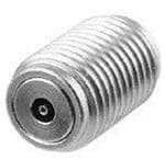
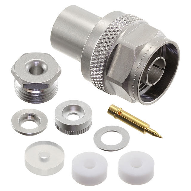
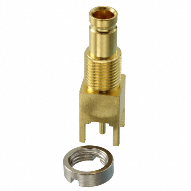
ICGOO电子元器件商城为您提供145-0701-002由AIM-Cambridge/Emerson设计生产,在icgoo商城现货销售,并且可以通过原厂、代理商等渠道进行代购。 145-0701-002价格参考。AIM-Cambridge/Emerson145-0701-002封装/规格:同轴连接器(RF), 面板安装,有螺纹 2.92mm 连接器 插孔,母形插口 50 欧姆 按下接通。您可以下载145-0701-002参考资料、Datasheet数据手册功能说明书,资料中有145-0701-002 详细功能的应用电路图电压和使用方法及教程。
Cinch Connectivity Solutions Johnson品牌的145-0701-002型号属于射频(RF)同轴连接器,广泛应用于需要高频信号传输的场景。该连接器具备良好的电气性能和机械稳定性,适用于通信、航空航天、国防、测试设备及工业控制系统等领域。

在通信领域,该型号常用于基站、天线系统和无线基础设施中,确保高频信号的可靠传输。在航空航天和国防应用中,其高可靠性和耐用性使其适用于雷达系统、导航设备和电子战系统。此外,145-0701-002也常用于实验室和测试环境,作为高频测试仪器与被测设备之间的连接接口,确保测试数据的准确性。

由于其具备优良的阻抗匹配能力和低插损特性,在高精度和高稳定性要求的工业控制系统中也有广泛应用。总体而言,该连接器适用于对信号完整性有高要求的各类高频电子系统。
| 参数 | 数值 |
| 产品目录 | |
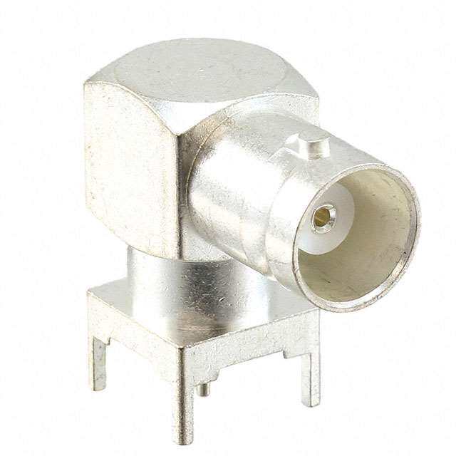
| 描述 | CONN SMK JACK STR 50 OHM SOLDER |
| 产品分类 | 同轴连接器 (RF) |
| 品牌 | Emerson Network Power Connectivity Johnson |
| 数据手册 | |
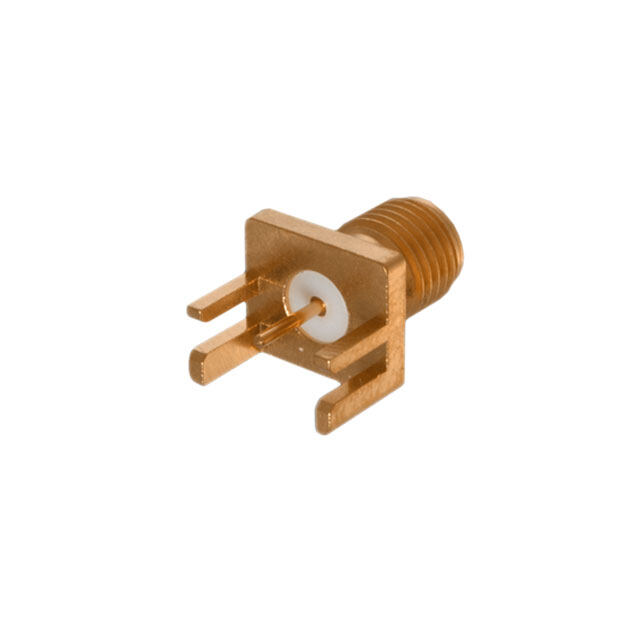
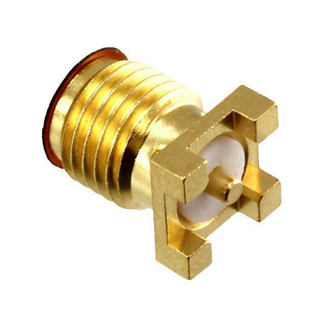
| 产品图片 |
|
| 产品型号 | 145-0701-002 |
| rohs | 无铅 / 符合限制有害物质指令(RoHS)规范要求 |
| 产品系列 | - |
| 中心触头材料 | 铜铍 |
| 中心触头镀层 | 金 |
| 产品目录绘图 |
|
| 产品目录页面 | |
| 介电材料 | 聚苯醚 (PPE) |
| 侵入防护 | - |
| 保护端接 | |
| 其它名称 | 1450701002 |
| 包装 | 散装 |
| 基体材料 | 不锈钢 |
| 基体表面 | - |
| 外壳颜色 | 银 |
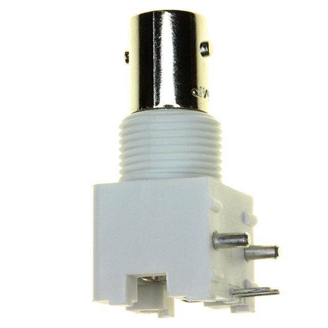
| 安装类型 | 面板安装 |
| 工作温度 | -65°C ~ 165°C |
| 标准包装 | 25 |
| 特性 | - |
| 特色产品 | http://www.digikey.cn/product-highlights/cn/zh/emerson-network-johnson-sma-connectors/4259 |
| 电缆组 | - |
| 紧固类型 | 有螺纹 |
| 触头端接 | |
| 连接器样式 | SMK |
| 连接器类型 | 插孔, 母形插口 |
| 阻抗 | 50 欧姆 |
| 频率-最大值 | 40GHz |
| 额定电压 | 335V |


.jpg)

PDF Datasheet 数据手册内容提取
SMK - 50 Ohm Connectors (2.92mm) INCHES (MILLIMETERS) • Jack Receptacle - Thread Mount Field Replaceable ACCEPTS PIN SIZE GOLD PLATED PASSIVATED .0120 +/- .0005 (0.305 +/- .013) 145-0701-001 145-0701-002 Mounting Hole Layout MATERIAL SPECIFICATIONS Mating Engagement for SMK (2.92mm) Series per MIL-STD-348 Bodies: Stainless steel per QQ-B-626, gold plated* per MIL-G-45204 .00005" min. or passivated per MIL-F-14072 B (EL) 300 Contacts: Female - beryllium copper per QQ-C-530, gold plated per MIL-G-45204 .00005" min. Contact Support Beads: PTFE fluorocarbon per ASTM D 1710 and ASTM D 1457 or modified PPE resin Seal Rings: Silicone rubber per ZZ-R-765 * All gold plated parts include a .00005" min. nickel underplate barrier layer. MECHANICAL RATINGS Engagement Design: MIL-STD-348, Series SMK (2.92mm) Engagement/Disengagement Force: 2 inch-pounds maximum Mating Torque: 7 to 10 inch-pounds Coupling Proof Torque: 15 inch-pounds minimum Coupling Nut Retention: 60 pounds minimum Contact Retention: 6 lbs. minimum axial force (captivated contacts) Cable Retention: Axial Force*(lbs)Torque (in-oz) .086 semi-rigid.....................................30 16 .141 semi-rigid.....................................60 55 *Or cable breaking strength whichever is less. Durability: 500 cycles minimum Notes: 1. ID of contact shall meet VSWR and connectivity requirements when mated with dia. .0355-.0365 male pin. Emerson Network Power Connectivity Solutions 299 Johnson Avenue SW, Waseca, MN 56093 • 800 -247- 8256 • +1 (507) 833-8822 • www.EmersonConnectivity.com
SMK - 50 Ohm Connectors (2.92mm) INCHES (MILLIMETERS) • ELECTRICAL RATINGS FIELD REPLACEABLE APPLICATION NOTES Impedance: 50 ohms The field replaceable connectors manufactured by Johnson Components ™, Frequency Range: 0-40 GHz are easy to install and replace. The hermetic seal is mounted into the circuit VSWR: (f = GHz) module wall and the connector can be removed and replaced without de- Semi-rigid straight cabled connectors and adapters..............1.20 Max stroying the hermeticity of the circuit housing. Field replaceable ( see typical return loss graph)............................ N/A Working Voltage: (Vrms maximum) The field replaceable connector creates a transition from microstrip circuitry Connectors for Cable T ype Sea Level 70K Feet to a coaxial transmission line. The SMK (2.92mm) seal pin diameter is .012 .086 semi-rigid and field replaceable.........................335 85 (.030) to minimize the capacitive effects on the circuit trace. For optimum .141 semi-rigid and adapters.....................................500 125 electrical performance, the transition from the hermetic seal to the microstrip Dielectric Withstanding Voltage: (VRMS minimum at sea level) trace must be properly compensated. Compensation involves adjusting .086 semi-rigid and field replaceable.............................................1000 the microstrip trace width to minimize any impedance discontinuities found .141 semi-rigid and adapters.........................................................1500 in the transition area. Corona Level: (Volts minimum at 70,000 feet) The plot shown below is representative of the typical return loss of a Johnson .086 semi-rigid and field replaceable...............................................250 Components™ field replaceable SMK connector. To produce the data shown .141 semi-rigid and adapters...........................................................375 below, a test fixture is created using the Johnson Components ™ SMK her- Insertion Loss: (dB maximum) metic seal. The fixture consists of a suitably thick spacer plate with the Adapters................................................0.06 f (GHz), tested at 6 GHz hermetic seal mounted flush to both surfaces. Two connectors are mounted Straight semi-rigid cable connectors.......0.03 f (GHz), tested at 10 GHz back to back around the fixture and the VSWR of this test assembly is Insulation Resistance: 5000 megohms minimum measured. The calculated return loss trace shown is equivalent to the square Contact Resistance: (milliohms maximum) Initial After Environmental root of the measured VSWR of the test assembly. Since the connectors Center contact straight cabled connectors...3.0* 4.0 tested are of identical design, it can be stated with fair accuracy that the Center contact adapters................................4.0 6.0 calculated data shown represents the response of a single field replaceable Field replaceable connectors........................6.0 8.0 connector and its transition to the hermetic seal. Outer contact (all connectors).......................2.0 N/A Body to cable (gold plated connectors).........0.5 N/A Although Johnson Components ™ does not publish a VSWR specification Body to cable (passivated connectors).........5.0 N/A for field replaceable connectors, typical connector return loss can be ex- RF Leakage: (dB minimum, tested at 2.5 GHz).............................-90dB pected to be less than -20 dB through 40 GHz. A VSWR specification is not RF High Potential Withstanding Voltage: (Vrms minimum, tested at 4 stated because an industry standard method for testing field replaceable and 7 MHz) = connectors does not exist. The actual performance of the connector is .086 semi-rigid and field replaceable..............................................670 dependent upon the following: .141 semi-rigid and adapters........................................................1000 1.For optimum electrical performance, Johnson Components ™ recommends the use of our standard 142-1000-033 hermetic seal with a pin diameter ENVIRONMENTAL RATINGS of .0120 (0.305) +/- .0005 (0.013). (Meets or exceed the applicable paragraph of MIL-C-39012) 2.It is recommended that the hermetic seal be mounted flush with the cir- Temperature Range: - 65°C to + 165 °C cuit housing. Tolerance variations between the hermetic seal and ma- Thermal Shock: MIL-STD-202, Method 107, Condition B chined housing do not always guarantee an optimum transition to the Corrosion: MIL-STD-202, Method 101, Condition B connector. Some manufacturers recommend an additional counterbore Shock: MIL-STD-202, Method 213, Condition I in the circuit housing to accommodate a solder washer during installation Vibration: MIL-STD-202, Method 204, Condition D of the seal. Johnson Components ™ does not recommend this type of Moisture Resistance: MIL-STD-202, Method 106 installation because if the counterbore is not completely filled with solder, electrical discontinuities may be created. 3.The transition between the hermetic seal pin and the microstrip trace will effect electrical performance, as stated above. Several different meth- ods of hermetic seal mounting and seal pin to microstrip trace attach- FIELD REPLACEABLE TEST ASSEMBLY ment are used in the industry. Emerson Network Power Connectivity Solutions 299 Johnson Avenue SW, Waseca, MN 56093 • 800 -247- 8256 • +1 (507) 833-8822 • www.EmersonConnectivity.com
Mouser Electronics Authorized Distributor Click to View Pricing, Inventory, Delivery & Lifecycle Information: C inch Connectivity Solutions: 145-0701-002