ICGOO在线商城 > 连接器,互连器件 > 接线座 - 配件 - 跳线 > 141J-1
 Datasheet下载
- 型号: 141J-1
- 制造商: Cinch
- 库位|库存: xxxx|xxxx
- 要求:
| 数量阶梯 | 香港交货 | 国内含税 |
| +xxxx | $xxxx | ¥xxxx |
查看当月历史价格
查看今年历史价格
141J-1产品简介:
ICGOO电子元器件商城为您提供141J-1由Cinch设计生产,在icgoo商城现货销售,并且可以通过原厂、代理商等渠道进行代购。 141J-1价格参考¥4.51-¥5.15。Cinch141J-1封装/规格:接线座 - 配件 - 跳线, 。您可以下载141J-1参考资料、Datasheet数据手册功能说明书,资料中有141J-1 详细功能的应用电路图电压和使用方法及教程。
Cinch Connectivity Solutions品牌的141J-1型号属于接线座-配件-跳线类产品,主要用于电子设备和通信系统中实现电路的灵活连接与配置。该型号跳线通常应用于以下场景:

1. 通信设备:在交换机、路由器、基站等通信设备中,用于快速连接或断开电路,便于调试和维护。

2. 工业控制系统:用于PLC控制柜、工控机等设备中,实现不同功能模块之间的快速接线与配置切换。

3. 测试与测量仪器:在电路测试、信号测量等场合,作为临时连接线使用,便于灵活改变电路连接方式。

4. 数据中心与服务器:在服务器背板、电源分配单元(PDU)等部位,用于短距离电源或信号的跳接连接。

5. 汽车电子系统:用于汽车控制模块之间的连接,便于生产线装配和后期维护。

该跳线具有良好的导电性和稳定性,适用于需要频繁更换连接方式或进行电路调试的场景,是电子工程和通信系统中常用的连接元件。
| 参数 | 数值 |
| 产品目录 | |
| 描述 | TERMINAL BLOCK JUMPER TYPE B接线端子工具和配件 TYPE B JUMPER-141 |
| 产品分类 | |
| 品牌 | Cinch |
| 产品手册 | http://www.cinch.com/view_item.cinch?section_id=28&sub_section_id=33§ion_title=Barrier%20Blocks&item_id=84 |
| 产品图片 |
|
| rohs | 符合RoHS无铅 / 符合限制有害物质指令(RoHS)规范要求 |
| 产品系列 | 接线端子工具和配件,Cinch 141J-1141 |
| 数据手册 | http://www.cinch.com/pdfs/Cinch_Catalog_2002.pdf#page=14 |
| 产品型号 | 141J-1 |
| 产品 | Tools & Accessories |
| 产品目录页面 | |
| 产品种类 | 接线端子工具和配件 |
| 其它名称 | 141J1 |
| 商标 | Cinch |
| 工厂包装数量 | 1000 |
| 标准包装 | 1,000 |
| 样式 | 环形隔板,环形舌片 |
| 类型 | Jumper |
| 配套使用产品/相关产品 | 141 系列 |
| 针脚数 | 2 |
| 颜色 | Black |


- 商务部:美国ITC正式对集成电路等产品启动337调查
- 曝三星4nm工艺存在良率问题 高通将骁龙8 Gen1或转产台积电
- 太阳诱电将投资9.5亿元在常州建新厂生产MLCC 预计2023年完工
- 英特尔发布欧洲新工厂建设计划 深化IDM 2.0 战略
- 台积电先进制程称霸业界 有大客户加持明年业绩稳了
- 达到5530亿美元!SIA预计今年全球半导体销售额将创下新高
- 英特尔拟将自动驾驶子公司Mobileye上市 估值或超500亿美元
- 三星加码芯片和SET,合并消费电子和移动部门,撤换高东真等 CEO
- 三星电子宣布重大人事变动 还合并消费电子和移动部门
- 海关总署:前11个月进口集成电路产品价值2.52万亿元 增长14.8%


PDF Datasheet 数据手册内容提取
Catalog No. C-865
CIN::APSE® High Speed Interconnect Technology
CIN::APSE® High-Speed Interconnect Technology ■ High signal speed capability enabling frequencies greater than 20 GHz. ■ Z-Axis,solderless,compression mount interconnect system. ■ Applications include production Land Grid Array (LGA) integrated circuit sockets,flex circuit to PCB,and parallel PCB to PCB interconnections. S ■ Provides solutions to many of the problems associated with through hole and surface mount E R soldered technology. U T ■ Enables upgrade and system maintenance strategies. A E ■ Available in custom I/O configurations and I/O counts from 1 to over 5,000. F ■ Offers low profile capabilities with compressed signal path length as short as 0.8 mm. ■ Contact centerline spacing of 1mm or greater. ■ Excellent reliability in commercial,military,and aerospace applications. ■ Application can result in lower installed and system maintenance costs. Contact Material: Molybdenum S CIN::APSEContact Plating: Gold L A RI Plunger Material: Copper alloy E T Plunger Plating: Gold A M Insulator Material: Liquid crystal polymer Packaging Tray Material: Anti-static ABS Button-Only Configuration with 0.020" (0.5 mm) Diameter L A Temperature Life Testing: 1000 Hours @ 200°C T N E Thermal Shock: 2,000 Cycles @ 20°C to 110°C M N Humidity: 5,000 Hours @ 30°C to 80°C, 80% RH O R Salt Spray: 96 Hours IC Component to Board Socket (LGA) VI N Low Temperature: Operates in liquid nitrogen (77°K) E Bellcore TR-NWT-001217: Passed with plungers Button-Only Configuration with 0.020" (0.5 mm) Diameter L DC Resistance: 15mΩaverage A C RI Inductance: Less than 1 nH T C Current-Carrying Capability: Up to 3 Amps. E EL Insulation Resistance: 25,000 MegΩ@ 500 VDC Dielectric Withstanding Voltage: 900 VACat sea level Button-Only Configuration with 0.020" (0.5 mm) diameter L Flex Circuit to PCB A C Durability: 25,000 Z-axis actuations (CIN::APSE contact only) NI Shock: 100 Gs;6 milliseconds, no discontinuity A H greater than 2 nanoseconds C ME Vibration: 20 Gs;10-20,000 Hz;no discontinuity greater than 2 nanoseconds Call Toll Free: 1 (800) 323-9612 1-1
CIN::APSE® High-Speed Interconnect Technology THE BUTTON CONTACT The unique construction of the CIN::APSE contact provides superior mechanical and electrical performance. It is constructed of randomly wound molybdenum wire that is formed into a cyclindrical shape.Standard CIN::APSE contact diameters are 0.020" and 0.040". Mechanical (cid:127)Small form factor (0.020" diameter by 0.32" min.high) (cid:127)Low compression force (approx.2.5 oz.min.per contact) (cid:127)Multiple beam structures (cid:127)Several points of contact per button Typical CIN::APSE Applications (cid:127)Extremely lightweight (cid:127)Natural wiping action (cid:127)LGA package I/O to PC board (IC packages, multi-chip modules) Electrical (cid:127)PC board to PC board (parallel processors, enhancement/mezzanine cards) (cid:127)Short signal path (cid:127)Flex circuit to PC board (rigid flex, harnessing) (cid:127)Very low inductance and resistance (cid:127)Signal integrity tested in the GHz range (cid:127)Flex circuit to ceramic (chip to harness) CIN::APSE APPLIED The basic button contact configuration consists of a single Step 1: Step 2: button installed in our patented Using alignment features, Add Z-Axis compression “hourglass”design. position the CIN::APSE and secure. connector between a LGA chip The hourglass cavity retains the package and PCB or two PCBs CIN::APSEcontact securely. that have matching footprints. Typically 0.003" protrudes from the top and the bottom of the insulator. 1-2 Call Toll Free: 1 (800) 323-9612
CIN::APSE® High-Speed Interconnect Technology 1 TYPICAL CONFIGURATION 1. Button-Only This is the basic CIN::APSE contact configuration.It is ideally suited for z-axis applications requiring minimum height, high density, and signal integrity. This configuration is used in LGA and IC sockets, PCB to PCB, and flex print circuit to PCBapplications. 2. Plunger-Button The addition of a gold-plated brass plunger increases the durability of the CIN::APSE contact system while also achieving additional height.This configuration suits itself especially well for PCB to PCB interconnect and those that require excessive handling. Other custom configurations are available.Contact Cinch for details. CIN::APSE Applications Due to its breakthrough nature, it is impossible to illustrate all of the applications CIN::APSE technology can address.The following applications illustrate only a portion of the types of interconnect problems that CIN::APSE can solve. Call Toll Free: 1 (800) 323-9612 1-3
CIN::APSE® High-Speed Interconnect Technology 1 VARIOUS CIN::APSE APPLICATIONS IC Component to Board Socket (LGA) PCB to PCB Hybrid Circuit to Flex to PCB LCD to Flex to PCB Cable to PCB/Flex Flex Circuit to PCB 1-4 Call Toll Free: 1 (800) 323-9612
COMMERCIAL Barrier Blocks Jones Plugs Circular Mini DIN Edge Connectors BNC
[.050” (1.27mm) Density Commercial Solder ICnutrpo/dWuicretion D-Microminiature] Cinch Commercial Products, consisting of Jones Plugs and Sockets, Barrier Blocks, Edge Cards, Two-Piece Commercial Dins, Mini Din Plugs, and their newest addition the 75ΩPress-Fit BNCReceptacle, provide a wide variety of connectors for the purchaser and designer to chose from. The Jones Plugs and Sockets have been utilized for decades and provide a quick, reliable, and economical means of solving your higher current-carrying capacity needs. Available in two series (300 and 2,400), these connectors can be found in data processing controls;amusement and vending machines;medical, communication, and test equipment;as well as industrial controls and heavy-duty, battery-powered equipment. Both series are available in a variety of cable and panel mounting options. 2 CinchBarrier Blocks are designed to simplify wiring work by reducing splicing, preventing current leaks and short circuits, and increasing insulation. Available in a variety of densities, these barrier blocks can be found in applications ranging from industrial controls to switching systems. Designed specially for applications where space is at a premium, the Cinch Mini Din family is ideal for personal computers, keyboard-mouse interface, hand-held electronic equipment, office-automation equipment, and audio and video equipment. Available in sizes 3 through 8 contact, the CinchMini Din family includes a fully shielded cable mounted plug in various cable lengths or cable mounted plug components for customers with high-volume assembly and overmold capabilities. Cinch Edge Card Connectors are available in a variety of styles on both .100 or .156 center spacing. The newest addition to the commercial family, the 75ΩPress-Fit BNC Receptacle is designed around a unique patented press-fit design that allows for multiple insertion into a backplane without loss of mechanical retention or electrical performance. When looking for time reliability to solve your commercial interconnect needs, look no further than Cinch Connectors. Whether it's a Jones Plug and Socket, Barrier Block, Edge Card, Mini Din plug, or our newest addition, the 75ΩBNCPress-Fit connector, you will always know years of customer satisfaction stand behind the product you chose. 2-1 Call Toll Free: 1 (800) 323-9612
Barrier Blocks ■ Interposing barriers between terminals yield higher electrical ratings and provide additional protection against frayed wire shorting. ES ■ A wide variety of barrier blocks makes it possible to select the combination of mechanical and R U electrical characteristics that best meet the exact requirements of your application. T A E ■ A wide selection of optional terminals and fanning strips permits the equipment designer to F choose the method of termination most suitable for his environmental specifications and manufacturing requirements. Insulation Material: Molded monoblock, general purpose phenolic, black, UL Rated 94V-1 S Eyelets: Material - Brass L A Plating - Nickel ERI Screws: Material - Steel T Plating - Nickel over copper flash A M Solder Terminals: Material - Brass Plating - Electro-Tin Marker Strip Material: Nema Grade XPC, UL Rated 94V-O L A T N E Operating Temperature: -55° to +300°F M N Certifications: UL Recognized - File E61245 O CSA - LR 31996 R VI N E Marketed exclusively through distribution. Call Toll Free: 1 (800) 323-9612 2-2
Barrier Blocks TERMINAL BLOCK QUICK REFERENCE Center-to- Number Single or Max. Max. Voltage Voltage Marker Center of Double Screw Operating Current Wire Watts/ Rating Rating Strip SeriesSpacing Terminals Row Size Voltage Rating Size Terminal w/Marker w/o Marker Mounting 140 .375 1-25 Double 5-40 250 Volts 15 Amps #16 3750 2000 1100 Bottom 141 .438 1-20 Double 6-32 250 Volts 20 Amps #14 5000 2400 1100 Bottom 142 .563 1-17 Double 8-32 250 Volts 30 Amps #10 7500 2600 1600 Bottom 150 .688 1-10 Double 10-32 250 Volts 40 Amps #10 10,000 2400 1500 Bottom 151 .875 1-8 Double 12-32 250 Volts 50 Amps #8 12,500 3400 1800 Bottom 152 1.125 1-6 Double 1/4-28 250 Volts 70 Amps #6 54,000 3800 2100 Bottom 164 .375 1-21 Double 6-32 250 Volts 15 Amps #14 3750 2000 1100 Bottom 540 .375 2-31 Double 5-40 600 Volts 15 Amps #16 3750 2300 2300 Top 541 .438 2-30 Double 6-32 600 Volts 20 Amps #14 5000 2800 2800 Top 542 .563 2-26 Double 8-32 600 Volts 30 Amps #10 7500 4000 4000 Top 176 .375 2-10 Single 5-40 250 Volts 15 Amps #16 3750 N/A 1100 N/A Marketed exclusively through distribution. 2-3 Call Toll Free: 1 (800) 323-9612
.375 Density, 5-40 x 3/16" Barrier Blocks BH Screw, Open Bottom, Series 140 Double Row Electrical Characteristics Voltage Rating: 250 VAC RMS maximum Current Rating: 15 Amps maximum Maximum Watts Per Terminal: 3750 Mechanical Characteristics Maximum Wire Size: #16 AWG Recommended Tightening Torque: 9 lb.-in. Dimensions Ordering Information No.of Standard Screw “M” “L” Terminals Catalog No. Dim. Dim. 1 1-140 .750 1.032 2 2-140 1.125 1.407 3 3-140 1.500 1.782 4 4-140 1.875 2.157 5 5-140 2.250 2.532 6 6-140 2.625 2.907 7 7-140 3.000 3.282 8 8-140 3.375 3.657 9 9-140 3.750 4.032 10 10-140 4.125 4.407 11 11-140 4.500 4.782 12 12-140 4.875 5.157 13 13-140 5.250 5.532 14 14-140 5.625 5.907 15 15-140 6.000 6.282 16 16-140 6.375 6.657 17 17-140 6.750 7.032 18 18-140 7.125 7.407 19 19-140 7.500 7.782 20 20-140 7.875 8.157 21 21-140 8.250 8.532 22 22-140 8.625 8.907 23 23-140 9.000 9.282 24 24-140 9.375 9.657 25 25-140 9.750 10.032 Call Toll Free: 1 (800) 323-9612 2-4 Marketed exclusively through distribution.
.375 Density, 5-40 x 3/16" Barrier Blocks BH Screw, Open Bottom, Series 140 Double Row Solder Terminal Options Dimensions “Y”Terminals “3/4W”Terminals “W”Terminals Ordering Information No.of Terminals Catalog No. Catalog No. Catalog No. 1 1-140-Y 1-140-3/4W 1-140-W 2 2-140-Y 2-140-3/4W 2-140-W 3 3-140-Y 3-140-3/4W 3-140-W 4 4-140-Y 4-140-3/4W 4-140-W 5 5-140-Y 5-140-3/4W 5-140-W 6 6-140-Y 6-140-3/4W 6-140-W 7 7-140-Y 7-140-3/4W 7-140-W 8 8-140-Y 8-140-3/4W 8-140-W 9 9-140-Y 9-140-3/4W 9-140-W 10 10-140-Y 10-140-3/4W 10-140-W 11 11-140-Y 11-140-3/4W 11-140-W 12 12-140-Y 12-140-3/4W 12-140-W 13 13-140-Y 13-140-3/4W 13-140-W 14 14-140-Y 14-140-3/4W 14-140-W 15 15-140-Y 15-140-3/4W 15-140-W 16 16-140-Y 16-140-3/4W 16-140-W 17 17-140-Y 17-140-3/4W 17-140-W 18 18-140-Y 18-140-3/4W 18-140-W 19 19-140-Y 19-140-3/4W 19-140-W 20 20-140-Y 20-140-3/4W 20-140-W 21 21-140-Y 21-140-3/4W 21-140-W 22 22-140-Y 22-140-3/4W 22-140-W 23 23-140-Y 23-140-3/4W 23-140-W 24 24-140-Y 24-140-3/4W 24-140-W 25 25-140-Y 25-140-3/4W 25-140-W Solder Terminals can be ordered separately. Terminal Type Catalog No. “Y” Y-140 “3/4W” 3/4W-140 “W” W-140 Marketed exclusively through distribution. 2-5 Call Toll Free: 1 (800) 323-9612
.375 Density, 5-40 x 3/16" Barrier Blocks BH Screw, Open Bottom, Series 140 Double Row Marker Strips Dimensions Standard “Y”Terminal 2 Ordering Information No.of Terminals Catalog No. Catalog No. 1 MS-1-140 MS-1-140-Y 2 MS-2-140 MS-2-140-Y 3 MS-3-140 MS-3-140-Y 4 MS-4-140 MS-4-140-Y 5 MS-5-140 MS-5-140-Y 6 MS-6-140 MS-6-140-Y 7 MS-7-140 MS-7-140-Y 8 MS-8-140 MS-8-140-Y 9 MS-9-140 MS-9-140-Y 10 MS-10-140 MS-10-140-Y 11 MS-11-140 MS-11-140-Y 12 MS-12-140 MS-12-140-Y 13 MS-13-140 MS-13-140-Y 14 MS-14-140 MS-14-140-Y 15 MS-15-140 MS-15-140-Y 16 MS-16-140 MS-16-140-Y 17 MS-17-140 MS-17-140-Y 18 MS-18-140 MS-18-140-Y 19 MS-19-140 MS-19-140-Y 20 MS-20-140 MS-20-140-Y 21 MS-21-140 MS-21-140-Y 22 MS-22-140 MS-22-140-Y 23 MS-23-140 MS-23-140-Y 24 MS-24-140 MS-24-140-Y 25 MS-25-140 MS-25-140-Y Use Standard Marker Strips for “3/4W”and “W”Solder Terminals. Accessories (cid:127) Jumpers (cid:127) Fanning Strips Marketed exclusively through distribution. Call Toll Free: 1 (800) 323-9612 2-6
.438 Density, 6-32 x 1/4" Barrier Blocks BH Screw, Open Bottom, Series 141 Double Row Electrical Characteristics Voltage Rating: 250 VAC RMS maximum Current Rating: 20 Amps maximum Maximum Watts Per Terminal: 5000 Mechanical Characteristics Maximum Wire Size: #14 AWG Recommended Tightening Torque: 12 lb.-in. Dimensions Ordering Information No.of Standard Screw “M” “L” Terminals Catalog No. Dim. Dim. 1 1-141 .875 1.187 2 2-141 1.312 1.625 3 3-141 1.750 2.062 4 4-141 2.187 2.500 5 5-141 2.625 2.938 6 6-141 3.062 3.375 7 7-141 3.500 3.812 8 8-141 3.938 4.250 9 9-141 4.375 4.687 10 10-141 4.813 5.125 11 11-141 5.250 5.562 12 12-141 5.687 6.000 13 13-141 6.125 6.437 14 14-141 6.562 6.875 15 15-141 7.000 7.312 16 16-141 7.437 7.750 17 17-141 7.875 8.187 18 18-141 8.312 8.625 19 19-141 8.750 9.062 20 20-141 9.187 9.500 Marketed exclusively through distribution. Call Toll Free: 1 (800) 323-9612 2-8
.438 Density, 6-32 x 1/4" Barrier Blocks BH Screw, Open Bottom, Series 141 Double Row Solder Terminal Options Dimensions “Y”Terminals “3/4W”Terminals “W”Terminals Ordering Information No.of Terminals Catalog No. Catalog No. Catalog No. 1 1-141-Y 1-141-3/4W 1-141-W 2 2-141-Y 2-141-3/4W 2-141-W 3 3-141-Y 3-141-3/4W 3-141-W 4 4-141-Y 4-141-3/4W 4-141-W 5 5-141-Y 5-141-3/4W 5-141-W 6 6-141-Y 6-141-3/4W 6-141-W 7 7-141-Y 7-141-3/4W 7-141-W 8 8-141-Y 8-141-3/4W 8-141-W 9 9-141-Y 9-141-3/4W 9-141-W 10 10-141-Y 10-141-3/4W 10-141-W 11 11-141-Y 11-141-3/4W 11-141-W 12 12-141-Y 12-141-3/4W 12-141-W 13 13-141-Y 13-141-3/4W 13-141-W 14 14-141-Y 14-141-3/4W 14-141-W 15 15-141-Y 15-141-3/4W 15-141-W 16 16-141-Y 16-141-3/4W 16-141-W 17 17-141-Y 17-141-3/4W 17-141-W 18 18-141-Y 18-141-3/4W 18-141-W 19 19-141-Y 19-141-3/4W 19-141-W 20 20-141-Y 20-141-3/4W 20-141-W Solder Terminals can be ordered separately. Terminal Type Catalog No. “Y” Y-141 “3/4W” 3/4W-141 “W” W-141 Marketed exclusively through distribution. 2-9 Call Toll Free: 1 (800) 323-9612
DURA-CON® .438 Density, 6-32 x 1/4" Barrier Blocks High Reliability BH Screw, Open Bottom, Series 141 All-Plastic Double Row Marker Strips Dimensions Standard “Y”Terminal 2 Ordering Information No.of Terminals Catalog No. Catalog No. 1 MS-1-141 MS-1-141-Y 2 MS-2-141 MS-2-141-Y 3 MS-3-141 MS-3-141-Y 4 MS-4-141 MS-4-141-Y 5 MS-5-141 MS-5-141-Y 6 MS-6-141 MS-6-141-Y 7 MS-7-141 MS-7-141-Y 8 MS-8-141 MS-8-141-Y 9 MS-9-141 MS-9-141-Y 10 MS-10-141 MS-10-141-Y 11 MS-11-141 MS-11-141-Y 12 MS-12-141 MS-12-141-Y 13 MS-13-141 MS-13-141-Y 14 MS-14-141 MS-14-141-Y 15 MS-15-141 MS-15-141-Y 16 MS-16-141 MS-16-141-Y 17 MS-17-141 MS-17-141-Y 18 MS-18-141 MS-18-141-Y 19 MS-19-141 MS-19-141-Y 20 MS-20-141 MS-20-141-Y Use Standard Marker Strip for “3/4W”and “W”Solder Terminals. Accessories (cid:127)Jumpers (cid:127)Fanning Strips Marketed exclusively through distribution. Call Toll Free: 1 (800) 323-9612 2-10
.563 Density, 8-32 x 5/16" Barrier Blocks BH Screw, Open Bottom, Series 142 Double Row Electrical Characteristics Voltage Rating: 250 VAC RMS maximum Current Rating: 30 Amps maximum Maximum Watts Per Terminal: 7500 Mechanical Characteristics Maximum Wire Size: #10 AWG Recommended Tightening Torque: 16 lb.-in. Dimensions Ordering Information No.of Standard Screw “M” “L” Terminals Catalog No. Dim. Dim. 1 1-142 1.125 1.531 2 2-142 1.687 2.094 3 3-142 2.250 2.656 4 4-142 2.812 3.219 5 5-142 3.375 3.781 6 6-142 3.937 4.344 7 7-142 4.500 4.906 8 8-142 5.062 5.468 9 9-142 5.625 6.031 10 10-142 6.187 6.594 11 11-142 6.750 7.156 12 12-142 7.312 7.719 13 13-142 7.875 8.281 14 14-142 8.437 8.844 15 15-142 9.000 9.406 16 16-142 9.562 9.969 17 17-142 10.125 10.531 Marketed exclusively through distribution. Call Toll Free: 1 (800) 323-9612 2-12
.563 Density, 8-32 x 5/16" Barrier Blocks BH Screw, Open Bottom, Series 142 Double Row Solder Terminal Options Dimensions “Y”Terminals “3/4W”Terminals “W”Terminals Ordering Information No.of Terminals Catalog No. Catalog No. Catalog No. 1 1-142-Y 1-142-3/4W 1-142-W 2 2-142-Y 2-142-3/4W 2-142-W 3 3-142-Y 3-142-3/4W 3-142-W 4 4-142-Y 4-142-3/4W 4-142-W 5 5-142-Y 5-142-3/4W 5-142-W 6 6-142-Y 6-142-3/4W 6-142-W 7 7-142-Y 7-142-3/4W 7-142-W 8 8-142-Y 8-142-3/4W 8-142-W 9 9-142-Y 9-142-3/4W 9-142-W 10 10-142-Y 10-142-3/4W 10-142-W 11 11-142-Y 11-142-3/4W 11-142-W 12 12-142-Y 12-142-3/4W 12-142-W 13 13-142-Y 13-142-3/4W 13-142-W 14 14-142-Y 14-142-3/4W 14-142-W 15 15-142-Y 15-142-3/4W 15-142-W 16 16-142-Y 16-142-3/4W 16-142-W 17 17-142-Y 17-142-3/4W 17-142-W Solder Terminals can be ordered separately. Terminal Type Catalog No. “Y” Y-142 “3/4W” 3/4W-142 “W” W-142 Marketed exclusively through distribution. 2-13 Call Toll Free: 1 (800) 323-9612
DURA-CON® .563 Density, 8-32 x 5/16" Barrier Blocks High Reliability BH Screw, Open Bottom, Series 142 All-Plastic Double Row Marker Strips Dimensions Standard “Y”Terminal 2 Ordering Information No.of Terminals Catalog No. Catalog No. 1 MS-1-142 MS-1-142-Y 2 MS-2-142 MS-2-142-Y 3 MS-3-142 MS-3-142-Y 4 MS-4-142 MS-4-142-Y 5 MS-5-142 MS-5-142-Y 6 MS-6-142 MS-6-142-Y 7 MS-7-142 MS-7-142-Y 8 MS-8-142 MS-8-142-Y 9 MS-9-142 MS-9-142-Y 10 MS-10-142 MS-10-142-Y 11 MS-11-142 MS-11-142-Y 12 MS-12-142 MS-12-142-Y 13 MS-13-142 MS-13-142-Y 14 MS-14-142 MS-14-142-Y 15 MS-15-142 MS-15-142-Y 16 MS-16-142 MS-16-142-Y 17 MS-17-142 MS-17-142-Y Use Standard Marker Strips for “3/4W”and “W”Solder Terminals. Accessories (cid:127) Jumpers (cid:127) Fanning Strips Marketed exclusively through distribution. Call Toll Free: 1 (800) 323-9612 2-14
.688 Density, 10-32 x 5/16" Barrier Blocks BH Screw, Open Bottom, Series 150 Double Row Electrical Characteristics Voltage Rating: 250 VAC RMS maximum Current Rating: 40 Amps maximum Maximum Watts Per Terminal: 10,000 Mechanical Characteristics Maximum Wire Size: #10 AWG Recommended Tightening Torque: 20 lb.-in. Dimensions Ordering Information No.of Standard Screw Y-Terminals “M” “L” Terminals Catalog No. Catalog No. Dim. Dim. 1 1-150 1-150-Y 1.375 1.812 2 2-150 2-150-Y 2.062 2.500 3 3-150 3-150-Y 2.750 3.187 4 4-150 4-150-Y 3.437 3.875 5 5-150 5-150-Y 4.125 4.562 6 6-150 6-150-Y 4.812 5.250 7 7-150 7-150-Y 5.500 5.938 8 8-150 8-150-Y 6.187 6.625 9 9-150 9-150-Y 6.875 7.312 10 10-150 10-150-Y 7.562 8.000 Marketed exclusively through distribution. Call Toll Free: 1 (800) 323-9612 2-16
.688 Density, 10-32 x 5/16" Barrier Blocks BH Screw, Open Bottom, Series 150 Double Row Marker Strips Dimensions Standard “Y”Terminal (.1678.846)TYP Ordering Information No.of Terminals Catalog No. Catalog No. 1 MS-1-150 MS-1-150-Y 2 MS-2-150 MS-2-150-Y 3 MS-3-150 MS-3-150-Y 4 MS-4-150 MS-4-150-Y 5 MS-5-150 MS-5-150-Y 6 MS-6-150 MS-6-150-Y 7 MS-7-150 MS-7-150-Y 8 MS-8-150 MS-8-150-Y 9 MS-9-150 MS-9-150-Y 10 MS-10-150 MS-10-150-Y Accessories None Available for 150 Series. Marketed exclusively through distribution. 2-17 Call Toll Free: 1 (800) 323-9612
.875 Density, 12-32 x 3/8" Barrier Blocks BH Screw, Open Bottom, Series 151 Double Row Electrical Characteristics Voltage Rating: 250 Volts maximum Current Rating: 50 Amps maximum Maximum Watts Per Terminal: 12,500 Mechanical Characteristics Maximum Wire Size: #8 Recommended Tightening Torque: 40 lb.-in. Dimensions Ordering Information No.of “M” “L” Marker Strip Terminals Catalog No. Dim.(in) Dim.(in) Catalog No. 1 1-151 1.750 2.282 N/A 2 2-151 2.625 3.157 MS-2-151 3 3-151 3.500 4.032 MS-3-151 4 4-151 4.375 4.907 MS-4-151 5 5-151 5.250 5.782 MS-5-151 6 6-151 6.125 6.657 MS-6-151 7 7-151 7.000 7.532 MS-7-151 8 8-151 7.875 8.407 MS-8-151 Solder Terminals can be ordered separately. Terminal Type Catalog No. “W” W-151 Marketed exclusively through distribution. Call Toll Free: 1 (800) 323-9612 2-18
1.25 Density, 1/4-28 x 1/2" Barrier Blocks BH Screw, Open Bottom, Series 152 Double Row Electrical Characteristics Voltage Rating: 250 Volts maximum Current Rating: 70 Amps maximum Maximum Watts Per Terminal: 54,000 Mechanical Characteristics Maximum Wire Size: #6 Recommended Tightening Torque: 75 lb.-in. Dimensions Ordering Information No.of “M” “L” Marker Strip Terminals Catalog No. Dim.(in) Dim.(in) Catalog No. 1 1-152 2.250 2.876 N/A 2 2-152 3.375 4.001 MS-2-152 3 3-152 4.500 5.126 MS-3-152 4 4-152 5.625 6.251 MS-4-152 5 5-152 6.750 7.376 MS-5-152 6 6-152 7.875 8.501 MS-6-152 Accessories None Available for 152 Series. Marketed exclusively through distribution. 2-19 Call Toll Free: 1 (800) 323-9612
.375 Density, 6-32 x 5/16" Barrier Blocks BH Screw, Open Bottom, Series 164 Double Row Electrical Characteristics Voltage Rating: 250 Volts maximum Current Rating: 15 Amps maximum Maximum Watts Per Terminal: 3750 Mechanical Characteristics Maximum Wire Size: #14 Recommended Tightening Torque: 12 lb.-in. Dimensions Ordering Information No.of “M” “L” Terminals Catalog No. Dim.(in) Dim.(in) 1 1-164 0.750 1.032 2 2-164 1.125 1.407 3 3-164 1.500 1.782 4 4-164 1.875 2.157 5 5-164 2.250 2.532 6 6-164 2.625 2.907 7 7-164 3.000 3.282 8 8-164 3.375 3.657 9 9-164 3.750 4.032 10 10-164 4.125 4.407 11 11-164 4.500 4.782 12 12-164 4.875 5.157 13 13-164 5.250 5.532 14 14-164 5.625 5.907 15 15-164 6.000 6.282 16 16-164 6.375 6.657 17 17-164 6.750 7.032 18 18-164 7.125 7.407 19 19-164 7.500 7.782 20 20-164 7.875 8.157 21 21-164 8.250 8.532 Marketed exclusively through distribution. Call Toll Free: 1 (800) 323-9612 2-20
.375 Density, 6-32 x 1/4" Barrier Blocks BH Screw, Open Bottom, Series 164 Double Row Solder Terminal Options Dimensions “Y”Terminals “3/4W”Terminals “W”Terminals Ordering Information No.of Terminals Catalog No. Catalog No. Catalog No. 1 1-164-Y 1-164-3/4W 1-164-W 2 2-164-Y 2-164-3/4W 2-164-W 3 3-164-Y 3-164-3/4W 3-164-W 4 4-164-Y 4-164-3/4W 4-164-W 5 5-164-Y 5-164-3/4W 5-164-W 6 6-164-Y 6-164-3/4W 6-164-W 7 7-164-Y 7-164-3/4W 7-164-W 8 8-164-Y 8-164-3/4W 8-164-W 9 9-164-Y 9-164-3/4W 9-164-W 10 10-164-Y 10-164-3/4W 10-164-W 11 11-164-Y 11-164-3/4W 11-164-W 12 12-164-Y 12-164-3/4W 12-164-W 13 13-164-Y 13-164-3/4W 13-164-W 14 14-164-Y 14-164-3/4W 14-164-W 15 15-164-Y 15-164-3/4W 15-164-W 16 16-164-Y 16-164-3/4W 16-164-W 17 17-164-Y 17-164-3/4W 17-164-W 18 18-164-Y 18-164-3/4W 18-164-W 19 19-164-Y 19-164-3/4W 19-164-W 20 20-164-Y 20-164-3/4W 20-164-W 21 21-164-Y 21-164-3/4W 21-164-W Marketed exclusively through distribution. 2-21 Call Toll Free: 1 (800) 323-9612
DURA-CON® [.0.35705” (D1e.2n7simtym, 6) -D32en xs i1ty/4" Barrier Blocks High Reliability SoBldHe Sr cCreuwp/,W Oipreen Bottom, Series 164 All-Plastic D-DMoicurbolme iRnoiawture] Marker Strips Dimensions Standard “Y”Terminal 2 Ordering Information No.of Terminals Catalog No. Catalog No. 1 N/A N/A 2 MS-2-140 MS-2-140-Y 3 MS-3-140 MS-3-140-Y 4 MS-4-140 MS-4-140-Y 5 MS-5-140 MS-5-140-Y 6 MS-6-140 MS-6-140-Y 7 MS-7-140 MS-7-140-Y 8 MS-8-140 MS-8-140-Y 9 MS-9-140 MS-9-140-Y 10 MS-10-140 MS-10-140-Y 11 MS-11-140 MS-11-140-Y 12 MS-12-140 MS-12-140-Y 13 MS-13-140 MS-13-140-Y 14 MS-14-140 MS-14-140-Y 15 MS-15-140 MS-15-140-Y 16 MS-16-140 MS-16-140-Y 17 MS-17-140 MS-17-140-Y 18 MS-18-140 MS-18-140-Y 19 MS-19-140 MS-19-140-Y 20 MS-20-140 MS-20-140-Y 21 MS-21-140 MS-21-140-Y Use Standard Marker Strips for “3/4W”and “W”Solder Terminals. Marketed exclusively through distribution. Call Toll Free: 1 (800) 323-9612 2-22
.375 Density, 5-40 x 1/4" Barrier Blocks BH Screw, Closed Bottom, Series 540 Double Row Electrical Characteristics Voltage Rating: 600 Volts maximum Current Rating: 15 Amps Maximum Watts Per Terminal: 3750 Mechanical Characteristics Maximum Wire Size: #16 Recommended Tightening Torque: 9 lb.-in. Dimensions Ordering Information No.of “M” “L” Marker Strip Terminals Catalog No. Dim.(in) Dim.(in) Catalog No. 2 2-540 1.125 1.407 MSX-2-540 3 3-540 1.500 1.782 MSX-3-540 4 4-540 1.875 2.157 MSX-4-540 5 5-540 2.250 2.532 MSX-5-540 6 6-540 2.625 2.907 MSX-6-540 7 7-540 3.000 3.282 MSX-7-540 8 8-540 3.375 3.657 MSX-8-540 9 9-540 3.750 4.032 MSX-9-540 10 10-540 4.125 4.407 MSX-10-540 11 11-540 4.500 4.782 MSX-11-540 12 12-540 4.875 5.157 MSX-12-540 13 13-540 5.250 5.532 MSX-13-540 14 14-540 5.625 5.907 MSX-14-540 15 15-540 6.000 6.282 MSX-15-540 16 16-540 6.375 6.657 MSX-16-540 17 17-540 6.750 7.032 MSX-17-540 18 18-540 7.125 7.407 MSX-18-540 19 19-540 7.500 7.782 MSX-19-540 20 20-540 7.875 8.157 MSX-20-540 21 21-540 8.250 8.532 MSX-21-540 22 22-540 8.625 8.907 MSX-22-540 23 23-540 9.000 9.282 MSX-23-540 24 24-540 9.375 9.657 MSX-24-540 25 25-540 9.750 10.032 MSX-25-540 26 26-540 10.125 10.407 MSX-26-540 27 27-540 10.500 10.782 MSX-27-540 28 28-540 10.875 11.157 MSX-28-540 29 29-540 11.250 11.532 MSX-29-540 30 30-540 11.625 11.907 MSX-30-540 31 31-540 12.000 12.282 MSX-31-540 Marketed exclusively through distribution. Call Toll Free: 1 (800) 323-9612 2-24
.438 Density, 6-32 x 1/4" Barrier Blocks BH Screw, Closed Bottom, Series 541 Double Row Electrical Characteristics Voltage Rating: 600 Volts maximum Current Rating: 20 Amps Maximum Watts Per Terminal: 5000 Mechanical Characteristics Maximum Wire Size: #14 Recommended Tightening Torque: 12 lb.-in. Dimensions Ordering Information No.of “M” “L” Marker Strip Terminals Catalog No. Dim.(in) Dim.(in) Catalog No. 2 2-541 1.314 1.626 MSX-2-541 3 3-541 1.752 2.064 MSX-3-541 4 4-541 2.190 2.502 MSX-4-541 5 5-541 2.628 2.940 MSX-5-541 6 6-541 3.066 3.378 MSX-6-541 7 7-541 3.504 3.816 MSX-7-541 8 8-541 3.942 4.254 MSX-8-541 9 9-541 4.380 4.692 MSX-9-541 10 10-541 4.818 5.130 MSX-10-541 11 11-541 5.256 5.568 MSX-11-541 12 12-541 5.694 6.006 MSX-12-541 13 13-541 6.132 6.444 MSX-13-541 14 14-541 6.570 6.882 MSX-14-541 15 15-541 7.008 7.320 MSX-15-541 16 16-541 7.446 7.758 MSX-16-541 17 17-541 7.884 8.196 MSX-17-541 18 18-541 8.322 8.634 MSX-18-541 19 19-541 8.760 9.072 MSX-19-541 20 20-541 9.198 9.510 MSX-20-541 21 21-541 9.636 9.948 MSX-21-541 22 22-541 10.074 10.386 MSX-22-541 23 23-541 10.512 10.824 MSX-23-541 24 24-541 10.950 11.262 MSX-24-541 25 25-541 11.388 11.700 MSX-25-541 26 26-541 11.826 12.138 MSX-26-541 27 27-541 12.264 12.576 MSX-27-541 28 28-541 12.702 13.014 MSX-28-541 29 29-541 13.140 13.452 MSX-29-541 30 30-541 13.578 13.890 MSX-30-541 Marketed exclusively through distribution. 2-25 Call Toll Free: 1 (800) 323-9612
.563 Density, 8-32 x 5/16" Barrier Blocks BH Screw, Closed Bottom, Series 542 Double Row Electrical Characteristics Voltage Rating: 600 Volts maximum Current Rating: 30 Amps Maximum Watts Per Terminal: 7500 Mechanical Characteristics Maximum Wire Size: #10 Recommended Tightening Torque: 16 lb.-in. Dimensions Ordering Information No.of “M” “L” Marker Strip Terminals Catalog No. Dim.(in) Dim.(in) Catalog No. 2 2-542 1.689 2.095 MSX-2-542 3 3-542 2.252 2.658 MSX-3-542 4 4-542 2.815 3.221 MSX-4-542 5 5-542 3.378 3.784 MSX-5-542 6 6-542 3.941 4.347 MSX-6-542 7 7-542 4.504 4.910 MSX-7-542 8 8-542 5.067 5.473 MSX-8-542 9 9-542 5.630 6.036 MSX-9-542 10 10-542 6.193 6.599 MSX-10-542 11 11-542 6.756 7.162 MSX-11-542 12 12-542 7.319 7.725 MSX-12-542 13 13-542 7.882 8.288 MSX-13-542 14 14-542 8.445 8.851 MSX-14-542 15 15-542 9.008 9.414 MSX-15-542 16 16-542 9.571 9.977 MSX-16-542 17 17-542 10.134 10.540 MSX-17-542 18 18-542 10.697 11.103 MSX-18-542 19 19-542 11.260 11.666 MSX-19-542 20 20-542 11.823 12.229 MSX-20-542 21 21-542 12.386 12.792 MSX-21-542 22 22-542 12.949 13.355 MSX-22-542 23 23-542 13.512 13.918 MSX-23-542 24 24-542 14.075 14.481 MSX-24-542 25 25-542 14.638 15.044 MSX-25-542 26 26-542 15.201 15.607 MSX-26-542 Marketed exclusively through distribution. Call Toll Free: 1 (800) 323-9612 2-26
.375 Density, 5-40 x 3/16" Barrier Blocks BH Screw, Dip Solder, Series 176 Single Row Electrical Characteristics Voltage Rating: 250 Volts maximum Current Rating: 15 Amps maximum Maximum Watts Per Terminal: 3750 Mechanical Characteristics Maximum Wire Size: 16 AWG Recommended Tightening Torque: 16 lb.-in. Dimensions L M Ordering Information With Mounting Ears No.of Catalog No. Catalog No. “M” “L” Terminals .125 Tail Lgth .184 Tail Lgth Dimension Dimension 2 2-176-2 2-176-3 1.125 1.469 3 3-176-2 3-176-3 1.500 1.844 4 4-176-2 4-176-3 1.875 2.219 5 5-176-2 5-176-3 2.250 2.594 6 6-176-2 6-176-3 2.625 2.969 7 7-176-2 7-176-3 3.000 3.344 8 8-176-2 8-176-3 3.375 3.719 9 9-176-2 9-176-3 3.375 4.094 10 10-176-2 10-176-3 4.125 4.469 Without Mounting Ears No.of Catalog No. Catalog No. “L” Terminals .125 Tail Lgth .184 Tail Lgth Dimension 2 2-176-2A 2-176-3A .719 3 3-176-2A 3-176-3A 1.094 4 4-176-2A 4-176-3A 1.469 5 5-176-2A 5-176-3A 1.844 6 6-176-2A 6-176-3A 2.219 7 7-176-2A 7-176-3A 2.594 8 8-176-2A 8-176-3A 2.969 9 9-176-2A 9-176-3A 3.344 10 10-176-2A 10-176-3A 3.719 11 11-176-2A 11-176-3A 4.094 12 12-176-2A 12-176-3A 4.469 Marketed exclusively through distribution. 2-27 Call Toll Free: 1 (800) 323-9612
DURA-CON® Barrier Blocks High Reliability Accessories All-Plastic Solder Terminals 3/4W,Y,and W Optional Terminals for use with Cinch terminal blocks. See chart for type and dimensions.(Below) 2 Ordering Information "3/4 W" Terminals - Dimensions Catalog A B C D E F Number in mm in mm in mm in mm in mm in mm 3/4W-140 .953 24.21 .719 18.20 .312 7.92 .062 1.57 .146 3.71 .094 2.39 3/4W-141 1.156 29.36 .680 17.27 .422 10.72 .078 1.98 .152 3.86 .125 3.18 3/4W-142 1.422 36.11 .797 20.24 .500 12.70 .094 2.39 .177 4.50 .125 3.18 "Y" Terminals - Dimensions Catalog A B C D E F Number in mm in mm in mm in mm in mm in mm Y-140 .281 7.14 .500 12.70 .136 3.45 .593 15.06 .093 2.36 .091 2.31 Y-141 .312 7.92 .625 15.88 .152 3.86 .781 19.83 .125 3.18 .103 2.62 Y-142 .421 10.69 .734 18.64 .177 4.50 .906 23.01 .125 3.18 .126 3.20 "W" Terminals - Dimensions Catalog A B C D E F Number in mm in mm in mm in mm in mm in mm W-140 1.219 30.96 .750 19.05 .312 7.92 .063 1.60 .146 3.71 .094 2.39 W-141 1.563 39.70 .938 23.83 .422 10.72 .078 1.98 .152 3.86 .125 3.18 W-142 1.875 47.63 1.094 27.79 .500 12.70 .094 2.39 .177 4.50 .125 3.18 Marketed exclusively through distribution. Call Toll Free: 1 (800) 323-9612 2-28
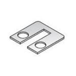
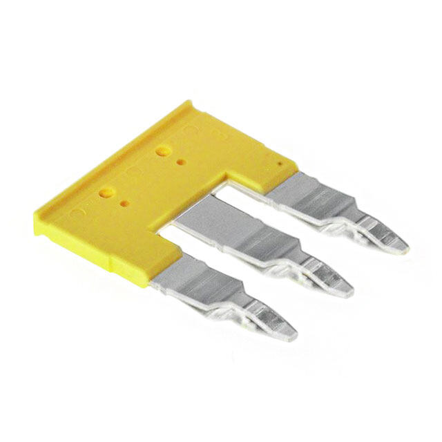
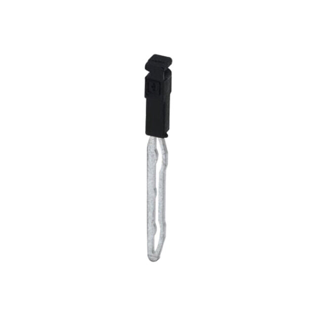
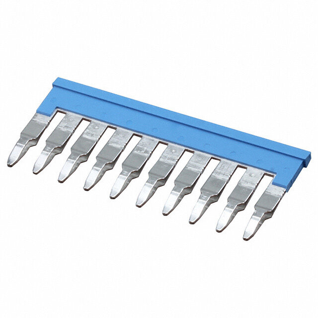
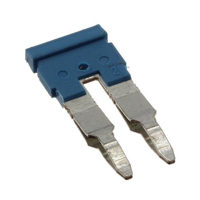
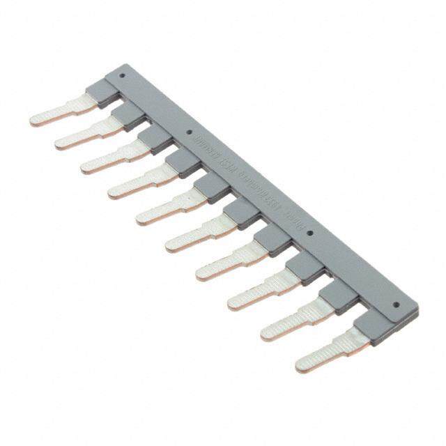
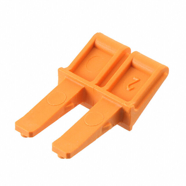
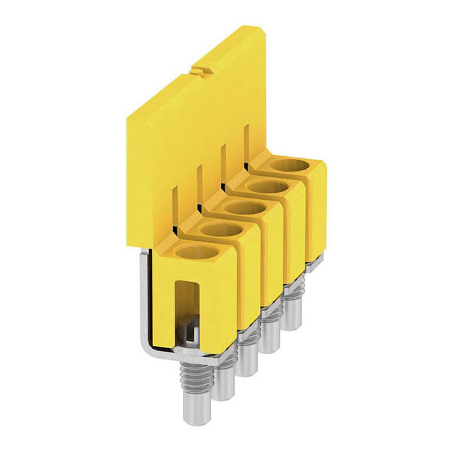
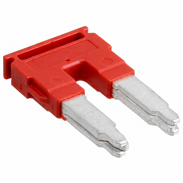
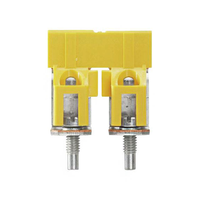
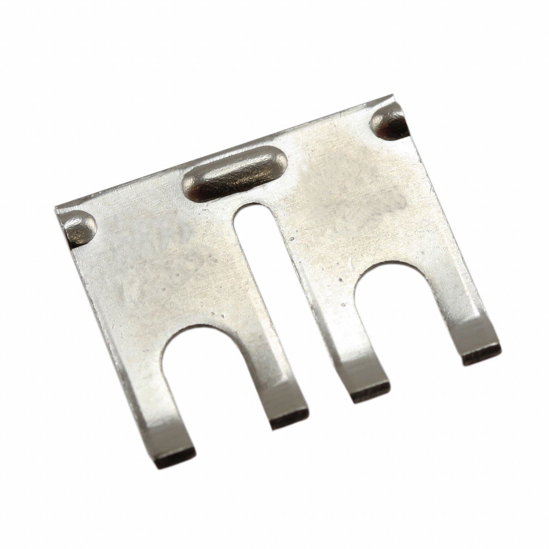
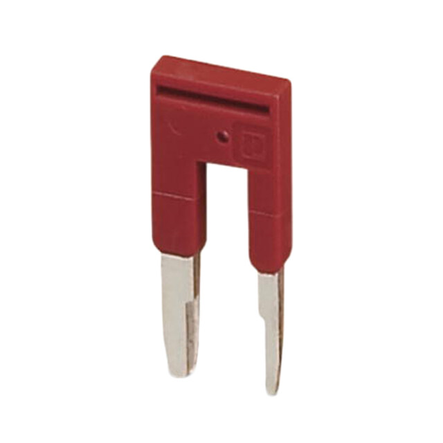
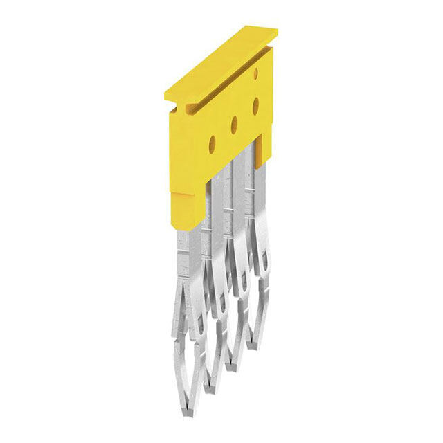
Barrier Blocks Accessories Quick Clamp Terminals Simplifies engaging of wires to barrier blocks. Wire is inserted into flared opening and screw is tightened.Screws are brass binder head type with nickel plating.Terminals are brass with tin plating.Includes two mating clamps and one screw. 2 QC-1 Shown Ordering Information Barrier Block Screw Wire Gauge Series Catalog No. Size Range AWG 141, 541 QC-1 6-32x5/16" 12 thru 22 142, 542 QC-2 8-32x3/8" 10 thru 16 Jumpers For connecting between adjacent terminals or alternate terminals.All jumpers are brass with nickel plating. Ordering Information Barrier Block Series Type Catalog No. 140 A 140J-1 141 B 141J-1 141 F 141J 142 F 95B Type A Type B Type C 142, 542 D 142J-1* 142, 542 E 142J-2 540 C 540J 541 C 541J 542 C 542J * Connects two alternate terminals Type D Type E Type F Marketed exclusively through distribution. 2-29 Call Toll Free: 1 (800) 323-9612
Barrier Block Fanning Strips Accessories ■ Minimize wiring errors. S ■ Available in straight and right-angle styles. E UR ■ Available with cable clamp hole on right or left side,designated T A by “L”or “R”at end of catalog number. E F ■ Cable clamp hole for securing cable/wires with lacing twine or ty-wrap. S L Insulation Material: UL 94HB rated XPC, chocolate A ERI Contact Material: Brass T A Contact Plating: Cadmium M Marketed exclusively through distribution. Call Toll Free: 1 (800) 323-9612 2-30
Barrier Block Fanning Strips Accessories Catalog Numbers and Dimensions for Fanning Strips for 140 Series Terminal Blocks Straight Type Dimensions Catalog No.6-160-R Catalog No.6-160B-R Ordering Information No.of Terminals Catalog No. Catalog No. Catalog No. Catalog No. 2 2-160-R 2-160-L 2-160B-R 2-160B-L 3 3-160-R 3-160-L 3-160B-R 3-160B-L 4 4-160-R 4-160-L 4-160B-R 4-160B-L 5 5-160-R 5-160-L 5-160B-R 5-160B-L 6 6-160-R 6-160-L 6-160B-R 6-160B-L 7 7-160-R 7-160-L 7-160B-R 7-160B-L 8 8-160-R 8-160-L 8-160B-R 8-160B-L 9 9-160-R 9-160-L 9-160B-R 9-160B-L 10 10-160-R 10-160-L 10-160B-R 10-160B-L 11 11-160-R 11-160-L 11-160B-R 11-160B-L 12 12-160-R 12-160-L 12-160B-R 12-160B-L 13 13-160-R 13-160-L 13-160B-R 13-160B-L 14 14-160-R 14-160-L 14-160B-R 14-160B-L 15 15-160-R 15-160-L 15-160B-R 15-160B-L 16 16-160-R 16-160-L 16-160B-R 16-160B-L 17 17-160-R 17-160-L 17-160B-R 17-160B-L 18 18-160-R 18-160-L 18-160B-R 18-160B-L 19 19-160-R 19-160-L 19-160B-R 19-160B-L 20 20-160-R 20-160-L 20-160B-R 20-160B-L 21 21-160-R 21-160-L 21-160B-R 21-160B-L Marketed exclusively through distribution. 2-31 Call Toll Free: 1 (800) 323-9612
DURA-CON® Barrier Block High Reliability FannFainngn iSntrgip Sstrips Accessories All-Plastic Catalog Numbers and Dimensions for Fanning Strips for 140 Series Terminal Blocks,Continued Right-Angle Type Dimensions 2 Catalog No.6-160A-R Ordering Information No.of Terminals Catalog No. Catalog No. 2 2-160A-R 2-160A-L 3 3-160A-R 3-160A-L 4 4-160A-R 4-160A-L 5 5-160A-R 5-160A-L 6 6-160A-R 6-160A-L 7 7-160A-R 7-160A-L 8 8-160A-R 8-160A-L 9 9-160A-R 9-160A-L 10 10-160A-R 10-160A-L 11 11-160A-R 11-160A-L 12 12-160A-R 12-160A-L 13 13-160A-R 13-160A-L 14 14-160A-R 14-160A-L 15 15-160A-R 15-160A-L 16 16-160A-R 16-160A-L 17 17-160A-R 17-160A-L 18 18-160A-R 18-160A-L 19 19-160A-R 19-160A-L 20 20-160A-R 20-160A-L 21 21-160A-R 21-160A-L Marketed exclusively through distribution. Call Toll Free: 1 (800) 323-9612 2-32
Barrier Block Fanning Strips Accessories Catalog Numbers and Dimensions for Fanning Strips for 141 Series Terminal Blocks Straight Type Dimensions No.of Terminals Catalog No. Catalog No. 2 2-161-R 2-161-L 2 3 3-161-R 3-161-L 4 4-161-R 4-161-L 5 5-161-R 5-161-L 6 6-161-R 6-161-L 7 7-161-R 7-161-L 8 8-161-R 8-161-L 9 9-161-R 9-161-L 10 10-161-R 10-161-L 11 11-161-R 11-161-L 12 12-161-R 12-161-L 13 13-161-R 13-161-L 14 14-161-R 14-161-L 15 15-161-R 15-161-L Catalog No.5-161-R 16 16-161-R 16-161-L 17 17-161-R 17-161-L 18 18-161-R 18-161-L 19 19-161-R 19-161-L 20 20-161-R 20-161-L Right-Angle Type Dimensions No.of Terminals Catalog No. Catalog No. 2 2-161A-R 2-161A-L 3 3-161A-R 3-161A-L 4 4-161A-R 4-161A-L 5 5-161A-R 5-161A-L 6 6-161A-R 6-161A-L 7 7-161A-R 7-161A-L 8 8-161A-R 8-161A-L 9 9-161A-R 9-161A-L 10 10-161A-R 10-161A-L 11 11-161A-R 11-161A-L 12 12-161A-R 12-161A-L 13 13-161A-R 13-161A-L 14 14-161A-R 14-161A-L 15 15-161A-R 15-161A-L 16 16-161A-R 16-161A-L 17 17-161A-R 17-161A-L 18 18-161A-R 18-161A-L 19 19-161A-R 19-161A-L Catalog No.5-161A-R 20 20-161A-R 20-161A-L Marketed exclusively through distribution. 2-33 Call Toll Free: 1 (800) 323-9612
Barrier Block Fanning Strips Accessories Catalog Numbers and Dimensions for Fanning Strips for 142 Series Barrier Blocks Straight Type Ordering Information Dimensions No.of Terminals Catalog No. Catalog No. 2 2-162-R 2-162-L 3 3-162-R 3-162-L 4 4-162-R 4-162-L 5 5-162-R 5-162-L 6 6-162-R 6-162-L 7 7-162-R 7-162-L 8 8-162-R 8-162-L 9 9-162-R 9-162-L 10 10-162-R 10-162-L 11 11-162-R 11-162-L 12 12-162-R 12-162-L 13 13-162-R 13-162-L 14 14-162-R 14-162-L Catalog No.5-162-R 15 15-162-R 15-162-L 16 16-162-R 16-162-L 17 17-162-R 17-162-L Right-Angle Type Ordering Information Dimensions No.of Terminals Catalog No. Catalog No. 2 2-162A-R 2-162A-L 3 3-162A-R 3-162A-L 4 4-162A-R 4-162A-L 5 5-162A-R 5-162A-L 6 6-162A-R 6-162A-L 7 7-162A-R 7-162A-L 8 8-162A-R 8-162A-L 9 9-162A-R 9-162A-L 10 10-162A-R 10-162A-L 11 11-162A-R 11-162A-L 12 12-162A-R 12-162A-L 13 13-162A-R 13-162A-L 14 14-162A-R 14-162A-L 15 15-162A-R 15-162A-L 16 16-162A-R 16-162A-L Catalog No.5-162A-R 17 17-162A-R 17-162A-L Marketed exclusively through distribution. Call Toll Free: 1 (800) 323-9612 2-34
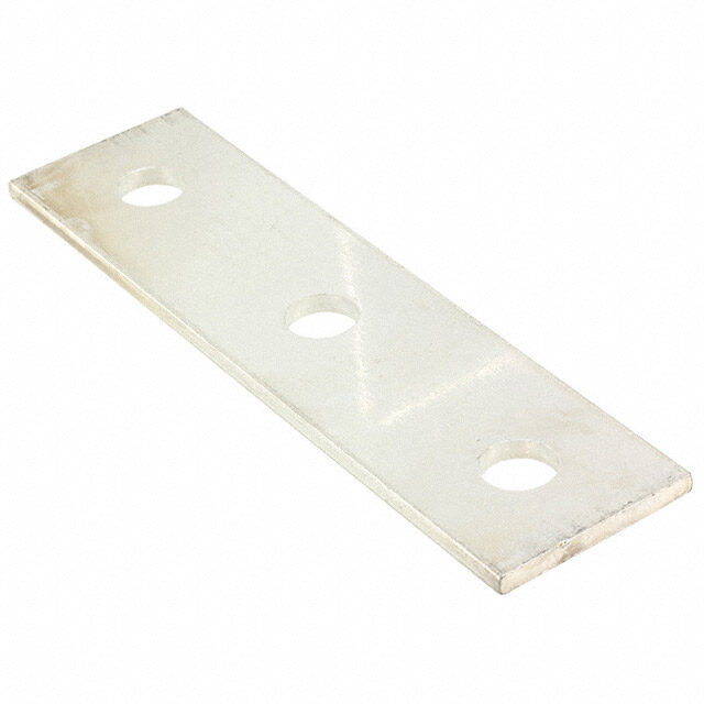
Barrier Block Lug-Type Terminal Strips Accessories Materials Insulation Material: UL 94 HB rated XPC, chocolate Contact Material: Steel Contact Plating: Cadmium Mechanical Characteristics Mounting Hole: .140" (3.56mm) diameter Strip Dimension: .0625" (1.59mm) thick x .375" (9.53mm) wide Lug Density: .375" (9.53mm) Ordering Information Mounting Lug Type Used In Position Catalog No. Centers 1 2 3 4 5 6 7 8 51 - 1 2 51A - 1 4 51B - 2 1 51C - 4 1 51F - 1/2 51L - 3 1 51R - 1 3 52 - 1 2 1 52A - 1 4 1 52B - 2 1 1 52C - 4 1 1 52R - 1 1 3 53 1.500 (38.10) 2 1 1 1 2 53A 1.500 (38.10) 4 1 1 1 4 53B .750 (19.05) 1 2 1 2 1 53C .750 (19.05) 1 4 1 4 1 53E - 1 2 1 1 53F - 1 4 1 1 54 1.875 (47.63) 2 1 1 1 1 2 54A 1.875 (47.63) 4 1 1 1 1 4 54B - 1 1 2 1 1 54C - 1 1 4 1 1 55 2.250 (57.15) 2 1 1 1 1 1 2 55A 2.250 (57.15) 4 1 1 1 1 1 4 55B 1.500 (38.10) 1 2 1 1 1 2 1 55C 1.500 (38.10) 1 4 1 1 1 4 1 56 2.625 (66.68) 2 1 1 1 1 1 1 2 56A 2.625 (66.68) 4 1 1 1 1 1 1 4 56B 1.875 (47.63) 1 2 1 1 1 1 2 1 56C 1.875 (47.63) 1 4 1 1 1 1 4 1 Dimensions Marketed exclusively through distribution. 2-35 Call Toll Free: 1 (800) 323-9612
Jones Multiple Density Plugs/Sockets Solder Eyelet Series 300 ■ Solder lug terminals with .093" x .062" (2.36mm x 1.57mm) wiring holes. ■ Two-contact "Jones" connector is round,all others are rectangular. ■ For use in cable-to-panel and cable-to-cable applications. ■ Designed for light and medium duty. S ■ Plug prongs are .156" (3.96mm) wide and .047" (1.19mm) thick. E R U ■ Polarized to prevent wrong-way insertion. T A E ■ Plugs have projecting flat blades,sockets have recessed twin bellows. F ■ Cable clamps of zinc and clear irridite-plated steel used for strain relief. ■ UL Recognized-file E170218 (UL 1977),E130965 (UL1863). ■ CSA-LR31996. ■ See Panel Cutout dimension on page (2-38). Insulation Material: Molded monoblock, general purpose phenolic, black UL94V-1 S L Contact Material: Plug: Brass A RI Socket: Phosphor bronze E AT Contact Plating: Cadmium M Operating Temperature: Up to +105°C Hood Material: UL 94V-0 rated thermoplastic L A Operating Voltage: 250 VAC RMS maximum C TRI Current Rating: 10 Amps C E Contact Resistance: 16 Milliohms maximum L E Marketed exclusively through distribution. Call Toll Free: 1 (800) 323-9612 2-36
Jones Multiple Density Plugs/Sockets Solder Eyelet Series 300 Polarizing Patterns - 300 Series Marketed exclusively through distribution. 2-37 Call Toll Free: 1 (800) 323-9612
DJoUnReAs-CON® Multiple Density HPliughg sR/eSloiacbkileittys Solder Eyelet ASellr-Pielass t3ic00 Mounting Dimensions A B C D Reference in mm in mm in mm in mm 303 .453 11.51 1.016 25.81 .750 19.05 - - 304 .719 18.26 .781 19.84 1.000 25.40 - - 306 .719 18.26 1.031 26.19 1.000 25.40 - - 2 308 .719 18.26 1.281 32.54 1.000 25.40 - - 310 .719 18.26 1.578 40.08 1.000 25.40 - - 312 .953 24.21 1.266 32.16 1.250 31.75 - - 315-12 .953 24.21 1.516 38.51 1.250 31.75 - - 315 1.016 25.81 1.641 41.68 1.375 34.93 - - 318 1.016 25.81 1.953 49.61 1.375 34.93 .625 15.88 321 1.016 25.81 2.266 57.56 1.375 34.93 .469 11.91 324 1.016 25.81 2.578 65.48 1.375 34.93 .625 15.88 327 1.016 25.81 2.891 73.43 1.375 34.93 .781 19.84 330 1.016 25.81 3.203 81.36 1.375 34.93 .938 23.83 333 1.016 25.81 3.516 89.31 1.375 34.93 1.094 27.79 NOTE: For 300 Series 2 through 33 contact angle bracket connectors.All mounting holes are .156" (3.96mm) dia.Maximum chassis thickness is .063" (1.59mm) for bottom mounting.Mounting holes are located on center line unless otherwise shown. Marketed exclusively through distribution. Call Toll Free: 1 (800) 323-9612 2-38
Jones [.M05u0lt”ip (l1e. 2D7emnsmity) Density Plugs/Sockets SSooldldeer rC Euype/leWt iWreith Angle Series 300 DB-Mraicckreotm/Linesias tAurneg]le Bracket With Angle Bracket Less Angle Bracket No.of Catalog No. Catalog No. No.of Catalog No. Catalog No. Contacts Plug Socket Contacts Plug Socket 2 P-302-AB S-302-AB 2 P-302-LAB S-302-LAB 3 P-303-AB S-303-AB 3 P-303-LAB S-303-LAB 4 P-304-AB S-304-AB 4 P-304-LAB S-304-LAB 6 P-306-AB S-306-AB 6 P-306-LAB S-306-LAB 8 N/A N/A 8 N/A N/A 10 P-310-AB N/A 10 P-310-LAB N/A 12 P-312-AB N/A 12 P-312-LAB N/A 15* N/A S-315-12-AB 15 N/A S-315-12-LAB 15 P-315-AB S-315-AB 15 P-315-LAB S-315-LAB 2 18 P-318-AB S-318-AB 18 P-318-LAB S-318-LAB 21 P-321-AB S-321-AB 21 P-321-LAB S-321-LAB 24 P-324-AB S-324-AB 24 P-324-LAB S-324-LAB 27 P-327-AB S-327-AB 27 P-327-LAB S-327-LAB 30 P-330-AB S-330-AB 30 P-330-LAB S-330-LAB 33 P-333-AB S-333-AB 33 P-333-LAB S-333-LAB X = length of plug contacts. This dimension does not apply to sockets. Y = length of plug or socket tails. No.of A B C D Contacts in mm in mm in mm in mm 2 .656 16.67 - - .969 24.61 1.219 30.96 3 1.000 25.40 .438 11.11 .750 19.05 1.062 26.99 4 .750 19.05 .688 17.46 1.000 25.40 1.312 33.34 6 1.000 25.40 .688 17.46 1.000 25.40 1.312 33.34 8 -- -- -- -- -- -- -- -- 10 1.562 39.69 .688 17.46 1.000 25.40 1.312 33.34 12 1.250 31.75 .938 23.81 1.250 31.75 1.562 39.69 15* 1.500 38.10 .938 23.81 1.250 31.75 1.562 39.69 *Special 15 contact arrangement to allow 12-position mating. L M Polarizing Reference in mm in mm Pin 15 1.625 41.28 See note - NO 18 1.938 49.23 1.250 31.75 NO 21 2.250 57.15 .938 23.81 NO 24 2.563 65.10 1.250 31.75 14 27 2.875 73.03 1.562 39.69 14 30 3.188 80.98 1.875 47.63 14 33 3.500 88.90 2.188 55.58 17 NOTE: 15-position plug and socket require only two mounting brackets, mounted on center of connector. Marketed exclusively through distribution. 2-39 Call Toll Free: 1 (800) 323-9612
DJoUnReAs-CON® [.050M” u(1lt.ip2l7em Dme)n Dsiteynsity HPliughg sR/eSloiacbkileittys SoldeSro lCduepr /EWyeirleet ASellr-Pielass t3ic00 D-MiFcrluosmhi nPilaattuere] 300 Series with Flush Plate (FP) No.of Catalog No. Catalog No. Contacts Plug Socket 2 P-302-FP S-302-FP 3 P-303-FP S-303-FP 4 P-304-FP S-304-FP 2 6 P-306-FP S-306-FP 8 N/A N/A 10 P-310-FP N/A 12 P-312-FP N/A X = length of plug contacts.This dimension does not apply to sockets. NOTE: Not available in contact sizes 15-33. Y = length of plug or socket tails. Dimensions - Plug or Socket No.of A B C D E Max. Contacts in mm in mm in mm in mm in mm 2 2.063 52.40 1.250 31.75 1.750 44.45 - - .719 18.26 3 2.063 52.40 1.250 31.75 1.750 44.45 .938 23.81 .500 12.70 4 2.063 52.40 1.250 31.75 1.750 44.45 .688 17.46 .750 19.05 6 2.063 52.40 1.250 31.75 1.750 44.45 .938 23.81 .750 19.05 8 -- -- -- -- -- -- -- -- -- -- 10 2.563 65.10 1.750 44.45 2.250 57.15 1.500 38.10 .750 19.05 12 2.563 65.10 1.750 44.45 2.250 57.15 1.188 30.16 1.000 25.40 Panel Cutout Dimensions A B C Reference in mm in mm in mm 303-FP .953 24.21 .516 13.11 1.750 44.45 304-FP .703 17.86 .766 19.46 1.750 44.45 306-FP .953 24.21 .766 19.46 1.750 44.45 308-FP -- -- -- -- -- -- 310-FP 1.516 38.51 .766 19.46 2.250 57.15 312-FP 1.203 30.56 1.016 25.81 2.250 57.15 Marketed exclusively through distribution. Call Toll Free: 1 (800) 323-9612 2-40
Jones [.050” M(1u.2lt7ipmlem D) eDnesnitsyity Plugs/Sockets Solder SCouldpe/Wr Eiryeelet Series 300 D-MicroEmndin Biartaucrkee]ts 300 Series with End Brackets (EB) No.of Catalog No. Catalog No. Contacts Plug Socket 15 P-315-EB S-315-EB 18 P-318-EB S-318-EB 21 P-321-EB S-321-EB 24 P-324-EB S-324-EB 28 P-328-EB S-328-EB 2 30 P-330-EB S-330-EB 33 P-333-EB S-333-EB NOTE: Not available in contact sizes 2-12. X = length of plug contacts.This dimension does not apply to sockets. Y = length of plug or socket tails. Dimensions No.of L M P Polarizing Contacts ±.031 (.79mm) ±.031 (.79mm) ±.063 (1.59mm) Pin 15 2.313 58.75 2.000 50.80 1.625 41.28 NO 18 2.625 66.68 2.313 58.75 1.938 49.23 NO 21 2.938 74.63 2.625 66.68 2.250 57.15 NO 24 3.250 82.55 2.938 74.63 2.563 65.10 14 27 3.563 90.50 3.250 82.55 2.875 73.03 14 30 3.875 98.43 3.563 90.50 3.188 80.98 14 33 4.188 106.38 3.875 98.43 3.500 88.90 17 Panel Cutout Dimensions A B C Reference in mm in mm in mm 315-EB 1.641 41.68 1.016 25.81 2.000 50.80 318-EB 1.953 49.61 1.016 25.81 2.313 58.75 321-EB 2.266 57.56 1.016 25.81 2.625 66.68 324-EB 2.578 65.48 1.016 25.81 2.938 74.63 327-EB 2.891 73.43 1.016 25.81 3.250 82.55 330-EB 3.203 81.36 1.016 25.81 3.563 90.50 333-EB 3.516 89.31 1.016 25.81 3.875 98.43 Marketed exclusively through distribution. 2-41 Call Toll Free: 1 (800) 323-9612
DJoUnReAs-CON® Multiple Density HPliughg sR/eSloiacbkileittys Solder Eyelet ASellr-Pielass t3ic00 Recessed Plate 300 Series with Recessed Plate (RP) No.of Catalog No. Catalog No. Contacts Plug Socket 2 P-302-RP S-302-RP 3 P-303-RP S-303-RP 4 P-304-RP S-304-RP 6 P-306-RP S-306-RP 2 8 N/A N/A 10 P-310-RP N/A 12 P-312-RP N/A NOTE: Not available in contact sizes 15-33. Y= length of plug or socket tails. Dimensions No.of A B C D Max. Contacts in mm in mm in mm in mm 2 2.063 52.40 1.500 38.10 1.750 44.45 1.350 34.29 3 2.063 52.40 1.500 38.10 1.750 44.45 1.350 34.29 4 2.063 52.40 1.500 38.10 1.750 44.45 1.350 34.29 6 2.063 52.40 1.500 38.10 1.750 44.45 1.350 34.29 8 -- -- -- -- -- -- -- -- 10 2.563 65.10 2.000 50.80 2.250 57.15 1.850 46.99 12 2.563 65.10 2.000 50.80 2.250 57.15 1.850 46.99 Marketed exclusively through distribution. Call Toll Free: 1 (800) 323-9612 2-42
Jones [.050” M(1u.2lt7ipmlem D) eDnesnitsyity Plugs/Sockets Solder SCouldpe/Wr Eiryeelet Series 300 D-MicroShmainlloiawtu Brera] cket 300 Series with Shallow Bracket (SB) No.of Catalog No. Catalog No. Contacts Plug Socket 15 P-315-SB S-315-SB 18 P-318-SB S-318-SB 21 P-321-SB S-321-SB 24 P-324-SB S-324-SB 27 P-327-SB S-327-SB 2 30 P-330-SB S-330-SB 33 P-333-SB S-333-SB NOTE: Not available in contact sizes 2-12. X = length of plug contacts.This dimension does not apply to sockets. Y = length of plug or socket tails. Dimensions No.of A M L Polarizing ±.031 (.79mm) ±.031 (.79mm) ±.063 (1.59mm) Polarizing Contacts in mm in mm in mm Pin 15 1.688 42.86 2.125 53.98 2.547 64.69 NO 18 2.000 50.80 2.438 61.93 2.859 72.62 NO 21 2.313 58.75 2.750 69.85 3.172 80.57 NO 24 2.625 66.68 2.063 52.40 3.484 88.49 14 27 2.938 74.63 3.375 85.73 3.797 96.44 14 30 3.250 82.55 3.688 93.68 4.109 104.38 14 33 3.563 90.50 4.000 101.60 4.422 112.32 17 Panel Cutout Dimensions A B C Reference in mm in mm in mm 315-SB 1.750 44.45 1.156 29.36 2.125 53.98 318-SB 2.063 52.40 1.156 29.36 2.438 61.93 321-SB 2.375 60.33 1.156 29.36 2.750 69.85 324-SB 2.688 68.28 1.156 29.36 3.062 77.77 327-SB 3.000 76.20 1.156 29.36 3.376 85.75 330-SB 3.313 84.15 1.156 29.36 3.688 93.68 333-SB 3.625 92.08 1.156 29.36 4.000 101.60 Marketed exclusively through distribution. 2-43 Call Toll Free: 1 (800) 323-9612
DJoUnReAs-CON® [.050M” u(1lt.ip2l7em Dme)n Dsiteynsity HPliughg sR/eSloiacbkileittys SoldeSro lCduepr /EWyeirleet ASellr-Pielass t3ic00 D-MiDcreoempi nBiraatcukreet] 300 Series Deep Bracket (DB) No.of Catalog No. Catalog No. Contacts Plug Socket 2 P-302-DB S-302-DB 3 P-303-DB S-303-DB 4 P-304-DB S-304-DB 6 P-306-DB S-306-DB 8 N/A N/A 2 10 N/A N/A 12 P-312-DB N/A 15 P-315-DB S-315-DB 18 P-318-DB S-318-DB 21 P-321-DB S-321-DB 24 P-324-DB S-324-DB 27 P-327-DB S-327-DB 30 P-330-DB S-330-DB 33 P-333-DB S-333-DB Dimensions Y = length of plug or socket tails. L M No.of ±.063 (1.60mm) ±.031 (.79mm) Polarizing Contacts in mm in mm Pin 15 2.813 71.44 2.375 60.33 NO 18 3.125 79.38 2.688 68.28 NO 21 3.437 87.31 3.000 76.20 NO 24 3.750 95.25 3.313 84.15 14 27 4.063 103.19 3.625 92.08 14 30 4.375 111.13 3.938 100.03 14 33 4.688 119.06 4.250 107.95 17 Panel Cutout Dimensions A B C Reference in mm in mm in mm 302-DB thru 312-DB 1.453 36.91 1.125 28.58 1.750 38.10 315-DB 2.000 50.80 1.438 36.53 2.376 60.35 318-DB 2.313 58.75 1.438 36.53 2.688 68.28 321-DB 2.625 66.68 1.438 36.53 3.000 76.20 324-DB 2.938 74.63 1.438 36.53 3.312 84.12 327-DB 3.250 82.55 1.438 36.53 3.626 92.10 330-DB 3.562 90.47 1.438 36.53 3.938 100.03 333-DB 3.875 98.43 1.438 36.53 4.250 107.95 Marketed exclusively through distribution. Call Toll Free: 1 (800) 323-9612 2-44
Jones [.050” M(1u.2lt7ipmlem D) eDnesnitsyity Plugs/Sockets Solder SCouldpe/Wr Eiryeelet Series 300 D-MicroWmitihn iHatouored] & 90° Clamp 300 Series with Hood and 90° Cable Clamp (CCE) No.of Catalog No. Catalog No. Contacts Plug Socket 2 P-302-CCE S-302-CCE 3 P-303-CCE S-303-CCE 4 P-304-CCE S-304-CCE 6 P-306-CCE S-306-CCE 8 N/A N/A 2 10 P-310-CCE N/A 12 P-312-CCE N/A 15 P-315-CCE S-315-CCE 18 P-318-CCE S-318-CCE 21 P-321-CCE S-321-CCE 24 P-324-CCE S-324-CCE 27 P-327-CCE S-327-CCE 30 P-330-CCE S-330-CCE 33 P-333-CCE S-333-CCE Dimensions A +.016 B +.016 C +.031 G Cable "D" No.of (.41mm) (.41mm) (.79mm) Opening Contacts in mm in mm in mm in mm in mm 2 .691 17.55 - - .953 24.21 .313 7.95 .313 7.95 3 1.034 26.26 .472 11.99 .953 24.21 .344 8.74 .250 6.35 4 .786 19.96 .724 18.39 .953 24.21 .453 11.51 .375 9.53 6 1.036 26.31 .724 18.39 .078 27.38 .469 11.91 .438 11.13 8 -- -- -- -- -- -- -- -- -- -- 10 1.592 40.44 .720 18.29 1.203 30.56 .359 9.12 .500 12.70 12 1.286 32.66 .974 24.74 1.203 30.56 .422 10.72 .563 14.30 No.of E L Cable Opening Polarizing Contacts in mm in mm in mm Pin 15 2.514 63.85 1.795 45.59 .563 14.30 NO 18 2.826 71.78 2.107 53.52 .563 14.30 NO 21 3.139 79.73 2.420 61.47 .625 15.88 NO 24 3.451 87.66 2.732 69.39 .625 15.88 14 27 3.764 95.61 3.045 77.34 .625 15.88 14 30 4.076 103.53 3.357 85.27 .750 19.05 14 33 4.389 111.48 3.670 93.22 .750 19.05 17 Marketed exclusively through distribution. 2-45 Call Toll Free: 1 (800) 323-9612
DJoUnReAs-CON® [.050M” u(1lt.ip2l7em Dme)n Dsiteynsity HPliughg sR/eSloiacbkileittys SoldeSro lCduepr /EWyeirleet ASellr-Pielass t3ic00 D-MiWcroitmh iHnoiaotudr e&] 180° Clamp 300 Series with Hood and 180° Cable Clamp (CCT) No.of Catalog No. Catalog No. Contacts Plug Socket 2 P-302-CCT S-302-CCT 3 P-303-CCT S-303-CCT 4 P-304-CCT S-304-CCT 6 P-306-CCT S-306-CCT 2 8 N/A N/A 10 P-310-CCT N/A 12 P-312-CCT N/A 15 P-315-CCT S-315-CCT 18 P-318-CCT S-318-CCT 21 P-321-CCT S-321-CCT 24 P-324-CCT S-324-CCT 27 P-327-CCT S-327-CCT 30 P-330-CCT S-330-CCT 33 P-333-CCT S-333-CCT Dimensions A ±.016 B ±.016 C ±.031 “D” Cable E ±.031 No.of (.41mm) (.41mm) (.79mm) Opening (.79mm) Contacts in mm in mm in mm in mm in mm 2 .691 17.55 - - .953 24.21 .375 9.53 .359 9.12 3 1.034 26.26 .472 11.99 .953 24.21 .313 7.95 .359 9.12 4 .786 19.96 .724 18.39 .953 24.21 .375 9.53 .469 11.91 6 1.036 26.31 .724 18.39 1.078 27.38 .438 11.13 .484 12.29 8 -- -- -- -- -- -- -- -- -- -- 10 1.592 40.44 .720 18.29 1.203 30.56 .500 12.70 .500 12.70 12 1.286 32.66 .974 24.74 1.203 30.56 .563 14.30 .469 11.91 No.of L Cable Opening Polarizing Contacts in mm in mm Pin 15 1.795 45.59 .563 14.30 NO 18 2.107 53.52 .563 14.30 NO 21 2.420 61.47 .625 15.88 NO 24 2.732 69.39 .625 15.88 14 27 3.045 77.34 .625 15.88 14 30 3.357 85.27 .750 19.05 14 33 3.670 93.22 .750 19.05 17 Marketed exclusively through distribution. Call Toll Free: 1 (800) 323-9612 2-46
Jones [.050” M(1u.2lt7ipmlem D) eDnesnitsyity Plugs/Sockets Solder SCouldpe/Wr Eiryeelet Series 300 D-Micro1m80in° iaCtluarme]p w/Locks 300 Series Plug with Hood and Lock (CCT-L) and Socket with Hood and Keeper (CCT-K) No.of Catalog No. Catalog No. Contacts Plug w/ Lock Socket w/ Keeper 2 P-302-CCT-L S-302-CCT-K 3 P-303-CCT-L S-303-CCT-K 4 P-304-CCT-L S-304-CCT-K 6 P-306-CCT-L S-306-CCT-K 8 N/A N/A 2 10 P-310-CCT-L N/A 12 P-312-CCT-L N/A 15 P-315-CCT-L S-315-CCT-K 18 P-318-CCT-L S-318-CCT-K 21 P-321-CCT-L S-321-CCT-K 24 P-324-CCT-L S-324-CCT-K 27 P-327-CCT-L S-327-CCT-K 30 P-330-CCT-L S-330-CCT-K 33 P-333-CCT-L S-333-CCT-K Socket Plug Dimensions A ±.016 B ±.016 C ±.031 F “D” Cable No.of (.41mm) (.41mm) (.79mm) Opening Polarizing Contacts in mm in mm in mm in mm in mm Pin 2 .691 17.5 - - .953 24.21 .359 9.12 .375 9.53 -- 3 1.034 26.26 .472 11.99 .953 24.21 .359 9.12 .313 7.94 -- 4 .786 19.96 .724 18.39 .953 24.21 .469 11.91 .375 9.53 -- 6 1.036 26.31 .724 18.39 1.078 27.38 .484 12.29 .438 11.13 -- 8 -- -- -- -- -- -- -- -- -- -- -- 10 1.592 40.44 .720 18.29 1.203 30.56 .500 12.70 .500 12.70 -- 12 1.286 32.66 .974 24.74 1.203 30.56 .469 11.91 .563 14.30 -- 15 1.795 45.59 1.100 27.94 1.850 46.99 .712 18.08 .563 14.30 NO 18 2.107 53.52 1.100 27.94 1.850 46.99 .712 18.08 .563 14.30 NO 21 2.420 61.47 1.100 27.94 1.850 46.99 .712 18.08 .625 15.88 NO 24 2.732 69.39 1.100 27.94 1.850 46.99 .712 18.08 .625 15.88 14 27 3.045 77.34 1.100 27.94 1.850 46.99 .712 18.08 .625 15.88 14 30 3.357 85.27 1.100 27.94 1.850 46.99 .712 18.08 .750 19.05 14 33 3.670 93.22 1.100 27.94 1.850 46.99 .712 18.08 .750 19.05 17 Marketed exclusively through distribution. 2-47 Call Toll Free: 1 (800) 323-9612
DURA-CON® [.050” (1.27mm) Density Multiple Density HMiigshc eRllealinabeiolituys Solder Cup/Wire Solder Eyelet All-Plastic D-Microminiature] JONES PLUGS AND SOCKETS 300 SERIES MATING CHART PLUGS MOUNTING AB DB FP RP EB SB CCE CCT CCT-L CCT-K LAB CONFIG. (cid:127) (cid:127) (cid:127) (cid:127) (cid:127) (cid:127) (cid:127) 2 AB * * * * (cid:127) (cid:127) DB (cid:127) (cid:127) (cid:127) (cid:127) (cid:127) (cid:127) FP * * * (cid:127) (cid:127) (cid:127) RP S EB (cid:127) * (cid:127) * (cid:127) * (cid:127) (cid:127) (cid:127) T E (cid:127) (cid:127) (cid:127) (cid:127) (cid:127) (cid:127) K SB * * * C O CCE (cid:127) (cid:127) (cid:127) (cid:127) (cid:127) (cid:127) (cid:127) (cid:127) S (cid:127) (cid:127) (cid:127) (cid:127) (cid:127) (cid:127) (cid:127) (cid:127) (cid:127) CCT (cid:127) CCT-L (cid:127) CCT-K (cid:127) (cid:127) (cid:127) (cid:127) (cid:127) (cid:127) (cid:127) (cid:127) (cid:127) (cid:127) (cid:127) LAB (cid:127) These are recommended configurations. (cid:127) * These are possible configurations, but not normally recommended. NOTE: Cinch layout S315-12 is available only in “AB”or “LAB”. Replacement Drive Pins for Series 300 Plugs and Sockets with Cable Caps and Clamps Dimensions Ordering Information Dim.L No.of +.005 (.13mm) No.of Contacts in mm Contacts Catalog No. 2 .687 17.45 2 302R 3 .468 11.89 3 303R 4,6,8,10* .718 18.24 4,6,8,10* 304R 12 .953 28.58 12 312R 15-33* 1.125 28.58 15-33* 333R *10 contact size and 15 through 33 contact sizes require two pins per unit;all other sizes require only one. Marketed exclusively through distribution. Call Toll Free: 1 (800) 323-9612 2-48
Jones Multiple Density Plugs/Sockets Solder Eyelet Series 2400 ■ For use in cable-to-cable and cable-to-panel applications. ■ Designed for medium duty. ■ Plug prongs are .250" (6.35mm) wide and .055" (1.40mm) thick. ■ Socket contacts have solder eyelet contacts of .093" diameters. ■ Polarized to prevent wrong-way insertion. ■ Plugs have projecting flat blades,sockets have recessed twin bellows. S ■ Cable clamps of zinc and clear irridite-plated steel are used for strain relief. E R U ■ Bifurcated bellows socket contact provides four individual flexing surfaces for T A maximum contact with the blade. E F ■ Plugs and sockets have recessed pockets with barriers around the contacts. ■ A shoulder extends around the face (mating) side of both plug and socket presenting a finished appearance when mounted in bracket or cap. ■ Intermates with existing 400 Series Products on the market. ■ UL Recognized - file - E17021B (UL1977) E130965 (1863). ■ CSA - LR31996-2. ■ Panel cutout dimensions (See page 2-57). Insulation Material: Molded monoblock, general purpose phenolic, black S Contact Material: Plug: Brass L A RI Socket: Phosphor bronze E T Contact Plating: Cadmium A M Operating Temperature: Up to +105°C Hood Material: Formed metal with dielectric liner in hood to prevent shorting L A Operating Voltage: 250 VAC RMS C TRI Current Rating: 15 Amps C E Current Resistance: 1.0 Milliohms maximum L E Marketed exclusively through distribution. Call Toll Free: 1 (800) 323-9612 2-50
Jones Multiple Density Plugs/Sockets Solder Eyelet Series 2400 Less Angle Bracket 2400 Series Less Angle Bracket No.of Catalog No. Catalog No. Contacts Plug Socket 2 N/A S-2402-LAB 4 P-2404-LAB S-2404-LAB 6 P-2406-LAB S-2406-LAB 8 P-2408-LAB S-2408-LAB 10 P-2410-LAB S-2410-LAB 12 P-2412-LAB S-2412-LAB Plug Socket Dimensions - Plug or Socket No.of M L Contacts in mm in mm 2 .563 14.29 .656 16.67 4 1.000 25.40 1.094 27.78 6 1.438 36.51 1.531 38.89 8 1.875 47.63 1.969 50.01 10 2.313 58.74 2.406 61.12 12 2.750 69.85 1.844 46.83 Marketed exclusively through distribution. 2-51 Call Toll Free: 1 (800) 323-9612
DJoUnReAs-CON® [.050M” u(1lt.i2p7lem Dme)n Dsiteynsity HPliughg sR/eSloiacbkileittys SoldeSro Clduepr /EWyeirleet ASellr-Pielass t2ic400 D-MiWcroitmh iAnniagtuler eB]racket 2400 Series with Angle Bracket No.of Catalog No. Catalog No. Contacts Plug Socket 2 N/A S-2402-AB 4 P-2404-AB S-2404-AB 6 P-2406-AB S-2406-AB 8 P-2408-AB S-2408-AB 10 P-2410-AB S-2410-AB 2 12 P-2412-AB S-2412-AB Plug Socket Dimensions - Plug or Socket No.of M L Contacts in mm in mm 2 .563 14.29 .656 16.67 4 1.000 25.40 1.094 27.78 6 1.438 36.51 1.531 38.89 8 1.875 47.63 1.969 50.01 10 2.313 58.74 2.406 61.12 12 2.750 69.85 2.844 72.24 Panel Cutout dimensions are on page 2-61. Marketed exclusively through distribution. Call Toll Free: 1 (800) 323-9612 2-52
Jones [.0M5u0l”t i(p1le.2 D7menmsi)t yDensity Plugs/Sockets SoSldoeldr eCr uEpy/eWleitre Series 2400 D-SMhiaclrloomwi nBiraatcukreet] 2400 Series with Shallow Bracket No.of Catalog No. Catalog No. Contacts Plug Socket 2 N/A S-2402-SB 4 P-2404-SB S-2404-SB 6 P-2406-SB S-2406-SB 8 P-2408-SB S-2408-SB 10 P-2410-SB S-2410-SB 2 12 P-2412-SB S-2412-SB Plug Socket Dimensions - Plug or Socket No.of L M R.Max. Contacts in mm in mm in mm 2 1.500 38.10 1.062 26.99 1.766 19.45 4 1.937 49.21 1.500 38.10 1.234 31.34 6 2.375 60.33 1.938 49.23 1.672 42.47 8 2.813 71.45 2.375 60.33 2.109 53.57 10 3.250 82.55 2.813 71.45 2.547 64.69 12 3.688 93.68 3.250 82.55 2.984 75.80 Panel Cutout dimensions are on page 2-61. Marketed exclusively through distribution. 2-53 Call Toll Free: 1 (800) 323-9612
DJoUnReAs-CON® [.050M” u(1lt.i2p7lem Dme)n Dsiteynsity HPliughg sR/eSloiacbkileittys SoldeSro Clduepr /EWyeirleet ASellr-Pielass t2ic400 D-MicDreoempi nBiaratuckree]t 2400 Series with Deep Bracket No.of Catalog No. Catalog No. Contacts Plug Socket 2 N/A S-2402-DB 4 P-2404-DB S-2404-DB 6 P-2406-DB S-2406-DB 8 P-2408-DB S-2408-DB 2 10 P-2410-DB S-2410-DB 12 P-2412-DB S-2412-DB Plug Socket Plug or Socket Dimensions - Plug or Socket No.of B L M Contacts in mm in mm in mm 2 .922 23.42 1.750 44.45 1.313 33.35 4 1.359 34.53 2.188 55.58 1.750 44.45 6 1.797 45.64 2.625 57.53 2.188 55.58 8 2.234 56.74 3.063 77.79 2.625 66.68 10 2.672 67.87 3.500 88.90 3.063 77.80 12 3.109 78.97 3.938 100.03 3.500 88.90 Panel Cutout dimensions are on page 2-61. Marketed exclusively through distribution. Call Toll Free: 1 (800) 323-9612 2-54
Jones [.050M” u(1lt.i2p7lem Dme)n Dsiteynsity Plugs/Sockets SoldeSro Clduepr /EWyierleet Series 2400 D-MicWroitmh iHnioaotudr e&] 90° Clamp 2400 Series with Hood and 90° Clamp No.of Catalog No. Catalog No. Contacts Plug Socket 2 N/A S-2402-CCE 4 P-2404-CCE S-2404-CCE 6 P-2406-CCE S-2406-CCE 8 P-2408-CCE S-2408-CCE 10 P-2410-CCE S-2410-CCE 2 12 P-2412-CCE S-2412-CCE Dimensions - Plug or Socket No.of L C Cable Opening Contacts in mm in mm in mm 2 .625 15.88 1.375 34.93 .375 9.53 4 1.062 26.99 1.375 34.93 .438 11.11 6 1.500 38.10 1.375 34.93 .438 11.11 8 1.937 49.21 1.344 34.13 .563 14.29 10 2.375 60.33 1.344 34.13 .563 14.29 12 2.813 71.45 1.312 33.34 .625 15.88 Marketed exclusively through distribution. 2-55 Call Toll Free: 1 (800) 323-9612
DJoUnReAs-CON® Multiple Density HPliughg sR/eSloiacbkileittys Solder Eyelet ASellr-Pielass t2ic400 With Hood & 180° Clamp 2400 Series with Hood and 180° Clamp No.of Catalog No. Catalog No. Contacts Plug Socket 2 N/A S-2402-CCT 4 P-2404-CCT S-2404-CCT 6 P-2406-CCT S-2406-CCT 8 P-2408-CCT S-2408-CCT 2 10 P-2410-CCT S-2410-CCT 12 P-2412-CCT S-2412-CCT Plug Socket Dimensions - Plug or Socket No.of L Cable Opening Contacts in mm in mm 2 .625 15.88 .313 7.94 4 1.062 26.99 .438 11.11 6 1.500 38.10 .438 11.11 8 1.937 49.21 .563 14.29 10 2.375 60.33 .563 14.29 12 2.813 71.45 .625 15.88 Marketed exclusively through distribution. Call Toll Free: 1 (800) 323-9612 2-56
Jones [.050” (1.27mm) Density Plugs/Sockets SoldPear nCeul pC/uWtoiruet Dimensions Series 2400 D-Microminiature] Panel Cutout Dimensions Angle Bracket A B C Reference in mm in mm in mm P-2402-AB -- -- -- -- -- -- S-2402-AB 1.188 30.16 1.008 25.60 1.015 25.78 P-2404-AB S-2404-AB 1.625 41.28 1.445 36.70 1.015 25.78 2 P-2406-AB S-2406-AB 2.063 52.40 1.886 47.83 1.015 25.78 P-2408-AB S-2408-AB 2.500 63.50 2.320 58.93 1.015 25.78 P-2410-AB S-2410-AB 2.938 74.63 2.758 70.05 1.015 25.78 P-2412-AB S-2412-AB 3.375 85.73 3.195 81.15 1.015 25.78 Panel Cutout Dimensions Shallow Bracket A B C Reference in mm in mm in mm P-2402-SB S-2402-SB 1.062 27.00 .813 20.64 1.156 29.37 P-2404-SB S-2404-SB 1.500 38.10 1.250 31.75 1.156 29.37 P-2406-SB S-2406-SB 1.938 49.22 1.688 42.86 1.156 29.37 P-2408-SB S-2408-SB 2.376 60.34 2.125 53.98 1.156 29.37 P-2410-SB S-2410-SB 2.812 71.44 2.563 65.10 1.156 29.37 P-2412-SB S-2412-SB 3.250 82.56 3.000 76.20 1.156 29.37 Panel Cutout Dimensions Deep Bracket A B C Reference in mm in mm in mm P-2402-DB S-2402-DB 1.312 33.34 .938 23.81 1.438 36.51 P-2404-DB S-2404-DB 1.750 44.46 1.375 34.93 1.438 36.51 P-2406-DB S-2406-DB 2.188 55.56 1.813 46.04 1.438 36.51 P-2408-DB S-2408-DB 2.624 66.68 2.250 57.15 1.438 36.51 P-2410-DB P-2410-DB 3.062 77.80 2.688 68.28 1.438 36.51 P-2412-DB S-2412-DB 3.500 88.90 3.125 79.38 1.438 36.51 Marketed exclusively through distribution. 2-57 Call Toll Free: 1 (800) 323-9612
Single-Ended Circular Mini DIN Plugs Cable Assembly ■ Contact positions 3,4,5,6,7,and 8. ■ Pre-assembled with standard shielded cable lengths;consult factory for other lengths. S ■ Molded-in strain relief. E R ■ Cable and overmold available in standard colors:black or beige. U AT ■ Contacts available with gold over nickel. E F ■ Shielding system designed to meet FCC requirements for EMI/RFI suppression. ■ UL Recognized - file E170218 (UL1977). ■ CSA Certified - file LR31996-6. Insulation Material: Plug Insulator: UL 94V-0 rated nylon Plug Overmold: PVC (black or beige) Cable Jacket: PVC (black or beige) Contact Material: Plug: Phosphor bronze Contact Plating: S L Option 1: Gold Flash over nickel underplate overall A RI Option 2: Option 1 plus additional gold in mating area for total E thickness of 30µin. T A Shield Material: Steel M Shield Plating: Nickel Standard Cable Shielded cable with 0.197 inch OD Composition: jacket over 28 AWG stranded wire conductors. Contact factory for custom cable requirements. L A Shock: MIL-STD-202, Method 213, Condition C T N Operating Temperature: -40°C to +70°C E M Heat Resistance: 196 hrs.at 100°C N O Salt Spray: MIL-STD-202, Method 101D, Condition D R Vibration: MIL-STD-202, Method 204, Condition B VI N Humidity: MIL-STD-202, Method 103, 48 hrs.at 90-95% RH at 40°C E PIN NO COLOR Voltage Rating: 500 VAC RMS, 707 VDC 1 BLACK AL Current Rating: 1 Amp at 100 VAC 2 GREEN C 2 Amps at 12 VDC TRI Contact Resistance: Contact to contact: 30 milliohms maximum 3 RED C Shield to shield: 50 milliohms maximum 4 BROWN E EL Insulation Resistance: 500 megohms minimum at 500 VDC 5 BLUE 100 megohms minimum after humidity 6 WHITE 7 YELLOW 8 GRAY L A C Durability: Withstands 500 mating/unmating cycles NI Mating Force: 10 lb.(4.5 kg) maximum A H Unmating Force: 1 lb.(0.9 kg) minimum C E Contact Retention: 3 lb.minimum M Marketed exclusively through distribution. Call Toll Free: 1 (800) 323-9612 2-58
Single-Ended Circular Mini DIN Plugs Cable Assembly Dimensions 3-Contact 4-Contact 5-Contact 6-Contact 7-Contact 8-Contact Ordering Information:(NOTE: One meter = 39.62 inches.) For cable assemblies with plug on one end. Plug features contacts with Option 1 plating (gold flash over nickel). Black Color Beige Color Cable Cable & Cable & No.of Length Overmold Overmold Contacts Meter Catalog No. Catalog No. 3 1 MDC-3P05 MDC-3P08 4 1 MDC-4P05 MDC-4P08 4 2 MDC-4P13 MDC-4P53 4 3 MDC-4P15 MDC-4P55 5 1 MDC-5P05 MDC-5P08 6 1 MDC-6P05 MDC-6P08 6 2 MDC-6P13 MDC-6P53 6 3 MDC-6P15 MDC-6P55 7 1 MDC-7P05 MDC-7P08 7 2 MDC-7P13 MDC-7P53 7 3 MDC-7P15 MDC-7P55 8 1 MDC-8P05 MDC-8P08 8 2 MDC-8P13 MDC-8P53 8 3 MDC-8P15 MDC-8P55 The above cable assemblies are highly recommended for general commercial applications. Contact factory for other lengths or colors. For cable assemblies with plug on one end. Plug features contacts with Option 2 plating (Option 1 with additional gold in mating area). NOTE: Total gold thickness in mating area is 30 microinches. Black Color Beige Color Cable Cable & Cable & No.of Length Overmold Overmold Contacts Meter Catalog No. Catalog No. 3 1 MDC-3P06 MDC-3P09 4 1 MDC-4P06 MDC-4P09 5 1 MDC-5P06 MDC-5P09 6 1 MDC-6P06 MDC-6P09 7 1 MDC-7P06 MDC-7P09 8 1 MDC-8P06 MDC-8P09 The above cable assemblies are recommended where greater contact durability is required. Additional Capabilities (cid:127)Additional lengths or colors of the above cable assemblies can be produced. Consult factory for custom orders. (cid:127)Custom-plated contacts can be provided. Consult factory for information. Marketed exclusively through distribution. 2-59 Call Toll Free: 1 (800) 323-9612
Plug Components for Circular Mini DIN Plugs Cable Termination ■ Individual components available for cable assembly with overmolding. ■ Plug insulator available with contact positions 3,4,5,6,7,and 8. ■ Seamless shield case is crimped to cable shield;designed to meet FCC requirements for EMI/RFI suppression. ES ■ One-piece shield case - no extra ferrules or shields required with R U Cinch Shield Crimp Tools. T EA ■ Contacts are crimp style and supplied on reels. F ■ Contacts available with gold over nickel in several options. ■ Tools available to facilitate reliable,efficient termination. ■ Terminates 24 to 30 AWG wire. ■ UL Recognized - file E170218 (UL1977). Insulation Material: Plug Insulator: 94 V-0 rated nylon Contact Material: Plug: Phosphor bronze Contact Plating: LS Option 1: Gold flash over nickel underplate overall A RI Option 2: Option 1 plus additional gold in mating area for E T total thickness of 30µin. A M Option 3: Option 1 plus additional gold in mating area for total thickness of 50µin. Shield Case Material: Steel Shield Case Plating: Nickel Dimensions 3-Contact 4-Contact 5-Contact 6-Contact 7-Contact 8-Contact Marketed exclusively through distribution. Call Toll Free: 1 (800) 323-9612 2-60
Plug Components for Circular Mini DIN Plugs Cable Termination Ordering Information For each Plug Assembly, the following components are needed: one plug insulator, one shield, and adequate contacts. Component Type Description Quantity Catalog No. Insulator 3 Position Insulator 1 MDX-3PI 4 Position Insulator 1 MDX-4PI 5 Position Insulator 1 MDX-5PI 6 Position Insulator 1 MDX-6PI 7 Position Insulator 1 MDX-7PI 8 Position Insulator 1 MDX-8PI Shield Case Metal Shield Case 1 MDX-PZ Contact Option 1 Plating 300 on Reel MDX-P-3A Option 1 Plating 15,000 on Reel MDX-P-15A Option 2 Plating 300 on Reel MDX-P-3B Option 2 Plating 15,000 on Reel MDX-P-15B Option 3 Plating 15,000 on Reel MDX-P-15D Tool Ordering Information The following tools are recommended for Mini Din Cable Plug Assembly. One tool of each type is required. Tool Type Description Catalog No. Contact Crimp Stripper-Crimper Machine MDT-P25 Complete, Includes Dies Contact Crimp Hand Tool MDT-P35 Crimps using 300 Contact Reels Contact Insertion Combination Contact Insertion MDT-P41 and Insulator Insertion Tool Contact Insertion Hand Tool MDT-P28 Fixture used with MDT-P28 MDT-P29 Insulator Insertion Insulator Insertion Bench Mounted Tool MDT-P34 Insulator Insertion Hand Tool MDT-P30 Shield Crimp Pneumatic Crimp Tool MDT-P81 Overview of Assembly Steps (cid:127)Prepare multi-conductor cable. (cid:127)Crimp contacts onto individual conductors using tool MDT-P25 or tool MDT-P35. (cid:127)Insert contact with conductor into insulator using tool MDT-P41 or have insertion tool MDT-P28 with insulator locating vice MDT-P29. (cid:127)Insert insulator into the shield case using tool MDT-P34 or MDT-P30. (cid:127)Crimp the shield case onto the cable shield using tool MDT-P81. (cid:127)Overmold plastic to complete the assembly. Marketed exclusively through distribution. 2-61 Call Toll Free: 1 (800) 323-9612
CARDCON™ .100" (2.54mm) Density Edge Connector Dip Solder Commercial ■ AT and XT versions available. ■ Dipsolder tails on .200" (5.08mm) row centers double readout. ■ Bifurcated semi-bellows contacts for added contact reliability. ■ Ideal for applications involving vibration or board irregularities. S ■ Contact positions: 12,15,18,20,22,25,28,30,31,36,37,40,43,44,49, E R 50,52,60,70,AT,and XT. U T ■ Accepts .062" (1.59mm) thick PC boards. A FE ■ Available less mounting ears,or with .128" (3.25mm) mounting holes or 4-40 threaded holes. ■ Meets applicable performance criteria of MIL-C-21097. ■ Tube packaging available. ■ UL Recognized - file E170218 (UL1977) E130965 (UL1863). Insulation Material: UL 94V-0 rated glass-filled polyester, black S L Contact Material: Spring brass A RI Standard Contact Plating: 10µin.selective gold over nickel, 50µin. E T nickel in contact area, tin on tails A M XT,AT Plating: 30µin.selective gold over 50µin.nickel in contact area, tin on tails Shock: Per MIL-STD-202E, Method 213, Condition C Operating Temperature: -65°C to +105°C L Vibration: Per MIL-STD-202E, Method 204, Condition B A T Humidity: Per MIL-STD-202, Method 103, Condition B N E Accessories: M Polarizing Key:Two types (order separately): N O a) for between-contact polarization and R b) for in-contact polarization. VI See page 2-74 for more information. N E Card Guide Posts: (order separately) Attach to mounting ears and guide PC board into connector. See page 2-74 for more information. L Withstanding Voltage: 650 VAC RMS (@ sea level) A C RI Current Rating: 3 Amps T C Contact Resistance: 10 Milliohms maximum E L E Insulation Resistance: 5000 Megohms minimum L A C Individual Contact Insertion and Separation Force: NI A 12oz.maximum with .070" (1.78mm) blade; H C 1 oz.minimum with .054" (1.37mm) blade E M Marketed exclusively through distribution. Call Toll Free: 1 (800) 323-9612 2-62
CARDCON™ .100" (2.54mm) Density Edge Connector Dip Solder Commercial Dimensions No.of A B C D E F Pos./Cont. in mm in mm in mm in mm in mm in mm 12/24 1.000 25.40 1.100 27.94 1.300 33.02 1.460 37.08 1.775 45.09 2.035 51.69 15/30 1.300 33.02 1.400 35.56 1.600 40.64 1.760 44.70 2.075 52.71 2.335 59.31 18/36 1.600 40.64 1.700 43.18 1.900 48.26 2.060 52.32 2.375 60.33 2.635 66.93 18/36+ 31/62IBM 5.000 127.00 5.100 129.54 5.300 134.62 5.460 138.68 5.775 146.69 6.035 153.29 20/40 1.800 45.72 1.900 48.26 2.100 53.34 2.260 57.40 2.575 65.41 2.835 72.01 22/24 2.000 50.80 2.100 53.34 2.300 58.42 2.460 62.48 2.775 70.49 3.035 77.09 25/50 2.300 58.42 2.400 60.96 2.600 66.04 2.760 70.10 3.075 78.11 3.335 84.71 28/56 2.600 66.04 2.700 68.58 2.900 73.66 3.060 77.72 3.375 85.73 3.635 92.33 30/60 2.800 71.12 2.900 73.66 3.100 78.74 3.260 82.80 3.575 90.81 3.835 97.41 31/62 2.900 73.66 3.000 76.20 3.200 81.28 3.360 85.34 3.675 93.35 3.935 99.95 31/62IBM 2.900 73.66 3.000 76.20 3.200 81.28 3.360 85.34 3.675 93.35 3.935 99.95 36/72 3.400 86.36 3.500 88.90 3.700 93.98 3.860 98.04 4.175 106.05 4.435 112.63 37/74 3.500 88.90 3.600 91.44 3.800 96.52 3.960 100.58 4.275 108.59 4.535 115.19 40/80 3.800 96.52 3.900 99.06 4.100 104.14 4.260 108.20 4.575 116.21 4.835 122.81 43/86 4.100 104.14 4.200 106.68 4.400 111.76 4.560 115.82 4.875 123.83 5.135 130.43 44/88 4.200 106.68 4.300 109.22 4.500 114.30 4.660 118.36 4.975 126.37 5.235 132.97 49/98 4.700 119.38 4.800 121.92 5.000 127.00 5.160 131.06 5.475 139.07 5.735 145.67 50/100 4.800 121.92 4.900 124.46 5.100 129.54 5.260 133.60 5.575 141.61 5.835 148.21 52/104 5.000 127.00 5.100 129.54 5.300 134.62 5.460 138.68 5.775 146.69 6.035 153.29 60/120 5.800 147.32 5.900 149.86 6.100 154.94 6.260 159.00 6.575 167.01 6.835 173.61 70/140 6.800 172.72 6.900 175.26 7.100 180.34 7.260 184.40 7.575 192.41 7.835 199.01 Ordering Information .128" (3.25mm) 4-40 No.of Less Mounting Ears Mounting Holes Threaded Holes Pos./Cont. Catalog No. Catalog No. Catalog No. 12/24 50-12SN-12 50-12SN-11 50-12SN-13 15/30 50-15SN-12 50-15SN-11 50-15SN-13 18/36 50-18SN-12 50-18SN-11 50-18SN-13 18/36+ 31/62 IBM 50-52SN-AT - - 20/40 50-20SN-12 50-20SN-11 50-20SN-13 22/44 50-22SN-12 50-22SN-11 50-22SN-13 25/50 50-25SN-12 50-25SN-11 50-25SN-13 28/56 50-28SN-12 50-28SN-11 50-28SN-13 30/60 50-30SN-12 50-30SN-11 50-30SN-13 31/62 50-31SN-12 50-31SN-11 50-31SN-13 31/62 IBM 50-31SN-XT - - 36/72 50-36SN-12 50-36SN-11 50-36SN-13 37/74 50-37SN-12 50-37SN-11 50-37SN-13 40/80 50-40SN-12 50-40SN-11 50-40SN-13 43/86 50-43SN-12 50-43SN-11 50-43SN-13 44/88 50-44SN-12 50-44SN-11 50-44SN-13 49/98 50-49SN-12 50-49SN-11 50-49SN-13 50/100 50-50SN-12 50-50SN-11 50-50SN-13 52/104 50-52SN-12 50-52SN-11 50-52SN-13 60/120 50-60SN-12 50-60SN-11 50-60SN-13 70/140 50-70SN-12 50-70SN-11 50-70SN-13 Marketed exclusively through distribution. 2-63 Call Toll Free: 1 (800) 323-9612
CARDCON™ .156" (3.96mm) Density Edge Connector Dip Solder/Solder Eyelet Commercial ■ Dip solder tails single readout and double readout on .140" (3.56mm) row centers or .200" (5.08mm) row centers. ■ Solder eyelet,single readout and double readout on .200" (5.08mm) row centers. ■ Available with unique tails for PC board retention;holds the connector S firmly on the board during wave soldering operations. E UR ■ Bifurcated semi-bellows contacts for added contact reliability. T A ■ Ideal for applications involving vibration or board irregularities. E F ■ Contact positions: 6,10,12,15,18,22,24,and 25. ■ Accepts single- or double-sided .062" (1.59mm) thick PC boards. ■ Available less mounting ears or with .128" (3.25mm) mounting hole. ■ Meets applicable performance criteria of MIL-C-21097. ■ UL Recognized - file E170218 (UL1977) E130965 (UL1863). S Insulation Material: UL 94V-0 rated glass-filled polyester, black L A RI Contact Material: Spring brass TE Contact Plating:10µ" selective gold over 30µ" nickel in contact A M area, tin on tails Shock: Per MIL-STD-202E, Method 213, Condition C Operating Temperature: -65°C to +105°C Vibration: Per MIL-STD-202E, Method 204, Condition B L A T Humidity: Per MIL-STD-202, Method 103, Condition B N E Accessories: M N Polarizing Key: Two types (order separately): O a) for between-contact polarization and R VI b) for in-contact polarization N See page 2-72 for more information. E Card Guide Posts: (order separately): Attach to mounting ears and guide PC board into connector See page 2-72 for more information. L Withstanding Voltage: 1800 VAC RMS (@ sea level) A C RI Current Rating: 5 Amps T C Contact Resistance: 6 Milliohms maximum E L Insulation Resistance: 5000 Megohms minimum E L A C NI Individual Contact Insertion and Separation Force: A 16 oz.maximum with .070" (1.78mm) blade; H C 1 oz.minimum with .054" (1.37mm) blade ME Marketed exclusively through distribution. Call Toll Free: 1 (800) 323-9612 2-64
[.050” (1.27mm) Density CARDCON™ .156" (3.96mm) Density Edge Connector Solder Cup/Wire Dip Solder/Solder Eyelet Commercial D-Microminiature] 2 Dimensions No.of A B C D Pos./Cont. In mm in mm in mm in mm 6/12 1.785 45.34 1.531 38.89 1.239 31.47 1.100 27.94 10/20 2.410 61.21 2.156 54.76 1.874 47.34 1.724 43.79 12/24 2.723 69.16 2.469 62.71 2.177 55.30 2.036 51.71 15/30 3.191 81.05 2.937 74.60 2.645 67.18 2.504 63.60 18/36 3.660 92.96 3.406 86.51 3.114 79.10 2.972 75.49 22/44 4.285 108.84 4.031 102.39 3.739 94.94 3.596 91.34 24/48 4.598 116.79 4.344 110.34 4.052 102.92 3.911 99.34 25/50 4.754 120.75 4.500 114.30 4.208 106.88 4.067 103.30 Ordering Information No.of Less Mounting Ears .128 Mounting Hole No.of Less Mounting Ears .128 Mounting Hole No.of Less Mounting Ears .128 Mounting Hole Pos./Cont.Catalog No. Catalog No. Pos./Cont.Catalog No. Catalog No. Pos./Cont.Catalog No. Catalog No. Dip solder tails,single readout,.156" (3.96mm) Dip solder tails,double readout,.140" (3.55mm) row Solder eyelet,single readout long spacing,.125" (3.18mm) long 6/6 50-6SN-8 50-6SN-7 6/6 50-6SN-6 50-6SN-5 6/12 50-12SN-4 50-12SN-2 10/10 50-10SN-8 50-10SN-7 10/10 50-10SN-6 50-10SN-5 10/20 50-20SN-4 50-20SN-2 12/12 50-12SN-8 50-12SN-7 12/12 50-12SN-6 50-12SN-5 12/24 50-24SN-4 50-24SN-2 15/15 50-15SN-8 50-15SN-7 15/15 50-15SN-6 50-15SN-5 15/30 50-30SN-4 50-30SN-2 18/18 50-18SN-8 50-18SN-7 18/18 50-18SN-6 50-18SN-5 18/36 50-36SN-4 50-36SN-2 22/22 50-22SN-8 50-22SN-7 22/22 50-22SN-6 50-22SN-5 22/24 50-44SN-4 50-44SN-2 24/24 50-24SN-8 50-24SN-7 24/24 50-24SN-6 20-24SN-5 24/48 50-48SN-4 50-48SN-2 25/25 50-25SN-8 50-25SN-7 25/25 50-25SN-6 50-25SN-5 25/50 50-50SN-4 50-50SN-2 Solder eyelet,double readout,.200" (5.08mm) Dip solder tails,double readout,.200" (5.08mm) Dip solder tails with unique board retention feature row spacing row spacing,.156" (3.96mm) long .200" (5.08mm) row spacing,.156" (3.96mm) long 6/12 50-12SN-10 50-12SN-9 6/12 50-12SN-3 50-12SN-1 6/12 50-12SN-3R 50-12SN-1R 10/20 50-20SN-10 50-20SN-9 10/20 50-20SN-3 50-20SN-1 10/20 50-20SN-3R 50-20SN-1R 12/24 50-24SN-10 50-24SN-9 12/24 50-24SN-3 50-24SN-1 12/24 50-24SN-3R 50-24SN-1R 15/30 50-30SN-10 50-30SN-9 15/30 50-30SN-3 50-30SN-1 15/30 50-30SN-3R 50-30SN-1R 18/36 50-36SN-10 50-36SN-9 18/36 50-36SN-3 50-36SN-1 18/36 50-36SN-3R 50-36SN-1R 22/24 50-44SN-10 50-44SN-9 22/44 50-44SN-3 50-44SN-1 22/44 50-44SN-3R 50-44SN-1R 24/28 50-48SN-10 50-48SN-9 24/48 50-48SN-3 50-48SN-1 24/48 50-48SN-3R 50-48SN-1R 25/50 50-50SN-10 50-50SN-9 25/50 50-50SN-3 50-50SN-1 25/50 50-50SN-3R 50-50SN-1R Marketed exclusively through distribution. 2-65 Call Toll Free: 1 (800) 323-9612
Edge Connector .156" (3.96mm) Density Dip High Reliability Solder/Solder Eyelet ■ Dip solder tails,single readout,.156" (3.96mm) long or .234" (5.94mm) long. ■ Dip solder tails,double readout,.156" (3.96mm) or .234" (5.94mm) long on .200" (5.08mm) row spacing,or .125" (3.18mm) long on .140" (3.56mm) row spacing. ■ Solder eyelet,single readout and double readout on .200" (5.08mm) row spacing. S RE ■ Patented bifurcated bellows contacts for added contact reliability. U T ■ Ideal for applications involving vibration or board irregularities. A E F ■ Contact positions: 6,10,12,15,18,22,and 25. ■ Available with or without mounting ears. ■ Accepts single- or double-sided .062" (1.59mm) thick PC boards. ■ UL Recognized - file E170218 (UL1977) E130965 (UL1863). LS Insulation Material: Diallyl phthalate, green A RI Contact Material: Phosphor bronze TE Contact Plating: 30µ" selective gold over 50µ" copper in the MA contact areas, 5µ" gold on tails Shock: Per MIL-STD-202E, Method 202 Operating Temperature: Dip solder: -65°C to +105°C Solder eyelet: -65°C to +125°C L Vibration: Per MIL-STD-202E, Method 204, Condition B A NT Humidity: Per MIL-STD-202E, Method 103, Condition B E Accessories: M N Polarizing Key: Two types (order separately): O a) for between-contact polarization and R VI b) for in-contact polarization N See page 2-74 for more information. E Card Guide Posts: (order separately): Attach to mounting ears and guide PC board into connector See page 2-74 for more information. Withstanding Voltage: 1800 VAC RMS (@ sea level) L A C Current Rating: 5 Amps RI T Contact Resistance: Dip solder: 6 Milliohms C E Solder eyelet: 10 Milliohms L E Insulation Resistance: 5000 Megohms minimum L A C NI Individual Contact Insertion and Separation Force: A 16 oz.maximum with .070" (1.78mm) blade; H C 1 oz.minimum with .054" (1.37mm) blade E M Marketed exclusively through distribution. Call Toll Free: 1 (800) 323-9612 2-66
Edge Connector .156" (3.96mm) Density Dip High Reliability Solder/Solder Eyelet Single Readout Double Readout With Plain Mounting Holes Dimensions No.of A B C D Pos./Cont. in mm in mm in mm in mm 6 1.100 27.94 1.239 31.47 1.531 38.80 1.785 45.34 10 1.724 43.79 1.864 47.35 2.156 54.76 2.410 61.21 12 2.036 51.71 2.177 55.30 2.469 62.71 2.723 69.16 15 2.504 63.60 2.645 67.18 2.937 74.60 3.191 81.05 18 2.972 75.49 3.114 79.10 3.406 86.51 3.660 92.96 20 3.286 83.46 3.427 87.05 3.719 94.46 3.973 100.91 22 3.596 91.34 3.739 94.97 4.031 102.39 4.285 108.84 25 4.067 103.30 4.208 106.88 4.500 114.30 4.754 120.75 Marketed exclusively through distribution. 2-67 CCaallll TToollll FFrreeee:: 11 ((880000)) 332233--99661122
DURA-CON® [.050” (1.27mm) Density Edge Connector .156" (3.96mm) Density Dip High Reliability Solder Cup/Wire High Reliability Solder/Solder Eyelet All-Plastic D-Microminiature] Ordering Information Single Readout .128" (3.25mm) Mounting Hole No.of Dip Solder Tails Dip Solder Tails Solder Pos./Cont. .156"(3.96mm) Long .234" (5.94mm) Long Eyelet Catalog No. Catalog No. Catalog No. 6/6 50-6H-10 50-6S-10 50-6H-20 2 10/10 50-10H-10 50-10S-10 50-10H-20 12/12 50-12R-10 50-12S-10 50-12H-20 15/15 50-15H-10 50-15S-10 50-15H-20 18/18 50-18H-10 50-18S-10 50-18H-20 20/20 50-20C-10 50-20S-10 50-20A-20 22/22 50-22H-10 50-22S-10 50-22H-20 25/25 50-25H-10 50-25S-10 50-25H-20 Double Readout .128" (3.25mm) Mounting Hole Less Mounting Ears Solder Eyelet Dip Solder Tails Dip Solder Tails Dip Solder Tails Dip Solder Tails No.of .234" (5.94mm) Long .156" (3.96mm) Long .125" (3.18mm) Long .125" (3.18mm) Long Pos./Cont. .200" (5.08mm) Between .200" (5.08mm) Between .140" (3.56mm) Between .140" (3.56mm) Between Row Spacing Row Spacing Row Spacing Row Spacing Catalog No. Catalog No. Catalog No. Catalog No. Catalog No. 6/12 50-12H-30 50-12S-20 50-12H-10 50-12H-30-2 50-12H-30-1 10/20 50-20H-30 50-20S-20 50-20H-10 50-20H-30-2 50-20H-30-1 12/24 50-24H-30 50-24S-20 50-24H-10 50-24H-30-2 50-24H-30-1 15/30 50-30H-30 50-30S-20 50-30H-10 50-30H-30-2 50-30H-30-1 18/36 50-36H-30 50-36S-20 50-36H-10 50-36H-30-2 50-36H-30-1 20/40 50-40A-30 50-40S-20 50-40B-10 22/44 50-44H-30 50-44S-20 50-44H-10 50-44H-30-2 50-44H-30-1 25/50 50-50H-30 50-50S-20 50-50H-10 50-50H-30-2 50-50H-30-1 Call Toll Free: 1 (800) 323-9612 2-68
Edge Connector .156" (3.96mm) Density High Reliability Card Extender ■ Solder terminations,double readout. ES ■ Bifurcated bellows type contacts. R U T EA ■ Contact positions: 6,10,12,15,18,22,and 25. F ■ Accepts .062" (1.59mm) thick double-sided PC boards. S Insulation Material: Diallyl phthalate, green L A RI Contact Material: Beryllium copper TE Contact Plating: 30µin.select gold over 50µin.nickel in the contact A M areas, 10µin.gold tails L A Shock: Per MIL-STD-202E, Method 213, Condition C T N ME Operating Temperature: -65°C to +125°C N O Vibration: Per MIL-STD-202E, Method 204, Condition B R VI N Humidity: Per MIL-STD-202E, Method 103, Condition B E L Withstanding Voltage: 830 VAC RMS (@ sea level) A C RI Current Rating: 5 Amps T C Contact Resistance: 5 Milliohms maximum E L E Insulation Resistance: 5000 Megohms minimum L A C Individual Contact Insertion and Separation Force: NI A 16 oz.maximum with .070" (1.78mm) blade; H C 1 oz.minimum with .054" (1.37mm) blade E M Marketed exclusively through distribution. Call Toll Free: 1 (800) 323-9612 2-70
Edge Connector .156" (3.96mm) Density High Reliability Card Extender Dimensions Dimensions No.of A B C D Pos./Cont. in mm in mm in mm in mm 6/12 1.100 27.94 1.239 31.47 1.531 38.88 1.785 45.33 10/20 1.724 43.79 1.864 47.34 2.156 54.76 2.410 61.21 12/24 2.036 51.71 2.177 55.29 2.469 62.71 2.723 69.16 15/30 2.504 63.60 2.645 67.18 2.937 74.59 3.191 81.05 18/36 2.972 75.48 3.114 79.09 3.406 86.51 3.660 92.96 22/44 3.596 91.33 3.739 94.97 4.031 102.38 4.285 108.83 25/50 4.067 103.30 4.208 106.88 4.500 114.30 4.754 120.75 Ordering Information No.of Pos./Cont. Catalog No. 6/12 50-12S-30 10/20 50-20S-30 12/24 50-24S-30 15/30 50-30S-30 18/36 50-36S-30 22/44 50-44S-30 25/50 50-50S-30 Marketed exclusively through distribution. 2-71 Call Toll Free: 1 (800) 323-9612
Edge Connector Card Guides Accessories Polarizing Keys Card Guides Card guide for .100" (2.54mm) and .156" (3.96mm) density edge connectors. Accepts .062" (1.59mm) thick PC boards. Card guides attach to mounting ears and guide printed circuit board into connector. Order separately. Material: Polypropylene Part No.50-GP-1 (Green) Part No.50-GP-1B (Black) Polarizing Keys Style A Style B Style C Style D Description Connector Family Material Style Catalog No. Between-contact type .156" Cellulose acetate B 50-PK In-contact type .156" Thermoset plastic B 50-PK1 Between-contact type .156" Glass epoxy A 50-PK2 Between-contact type .156" Glass epoxy D 50-PK2M Between-contact type .100" Glass-filled nylon C 50-PK3 In-contact type .156" Thermoplastic B 50-PK4 Marketed exclusively through distribution. Call Toll Free: 1 (800) 323-9612 2-72
Socket Commercial Plug Buttons Miscellaneous Plug Buttons Dimensions Nickel-plated steel.Spring tension prongs. For Hole Cup 41V provides ventilation wherever required. Diameter Diameter in mm in mm Catalog No. .250 6.35 .406 10.32 41A .375 9.53 .500 12.70 41B .500 12.70 .656 16.67 41C .625 15.88 .797 20.24 41D .750 19.05 .938 23.81 41E .875 22.23 1.062 26.99 41F 1.000 25.40 1.156 29.37 41G 1.250 31.75 1.438 36.51 41H 1.000 25.40 1.156 29.37 41V Call Toll Free: 1 (800) 323-9612 2-74
Press-Fit BNC Coaxial Connector Board Mount ΩΩ Receptacle for 75 Applications ■ Solderless,Press-Fit Installation. S ■ Strong,One-Piece Cast Body. E R U ■ Standard BNCInterface. T A E ■ 75ΩΩ Impedance. F ■ Meets Lucent Technologies (AT&T) Requirements. Compliant version, Pt.No.299 99 00 134 is also available. For more information please Body: One-piece diecast zinc per QQ-Z-363 contact us at 1-800-323-9612 Plating: Nickel, 150µin.min.per QQ-N-290 over copper, 200µin. S AL min.per MIL-C-14550 RI Center Contact: Beryllium copper E AT Plating: Gold, 30µin.minimum over nickel, 50µin.minimum M Insulator: Teflon TFE per ASTMD1710 Unique patented press-fit connector design allows for multiple insertions into a backplane without loss of mechanical retention or electrical Impedance: 75Ω performance. Frequency Range: 0 to 4 GHz L The design requirements for nominal PC board A RF Leakage: > -55 dB C mounting holes and thickness are as follows: TRI Insertion Loss: .2dB maximum @ 2 GHz C Insertion Forces: E VSWR: 1.024 L E Working Voltage: <500 VAC RMS@ sea level .093 Board Thickness: 200 lb.max. .250 Board Thickness: 500 lb.max. Insulation Resistance: >5000 MOhms @ 500 VDC Withdraw Forces: .093 Board Thickness: 100 lb.max. Connector Insertion Force: <500 lb.* .250 Board Thickness: 200 lb.max. Connector Removal Force: >100 lb.* AL Center Contact Insertion Force: <2.0 lb.* The Cinch Press-Fit BNC surpasses these C NI Center Contact Removal Force: >2.0 oz.* requirements with a unique, non-symmetrical A *Requirements are for two connector insertions into the same PC board H ground leg design. This design allows the C mounting holes. PC board thickness can range from .093" to .300" thick. E connector to be inserted, removed, rotated 180o, M PC board hole requirements are as follows: and reinserted into the same location on the Ground Legs: .059" Nom. board without loss of mechanical or electrical Center Contact: .040" Nom. performance. Call Toll Free: 1 (800) 323-9612 2-76
Press-Fit BNC Coaxial Connector Board Mount ΩΩ Receptacle for 75 Applications Production Insertion Tool Design Press-Fit BNCConnector Dimensions Ordering Information Catalog Number: BNC-1-PF Standard Package: Anti-Static Tube, 48 Connectors Per Tube 2-77 Call Toll Free: 1 (800) 323-9612
CYLINDRICAL C48 Series/MIL-C-26500 Accessories & Application Tooling Boeing: BACC45 / BACC63 Series
MIL-C-26500 Introduction C48 Series ■ Qualified to MIL-C-26500. ■ Styles qualified to Boeing BACC45 Series. ■ Styles qualified to Boeing BACC63 Series. S ■ Power Contact Sizes: 20,16,and 12. E R U ■ Coax Contacts Available: Size 12 and 8. T A E ■ Contacts: Crimp - Front release. F ■ Optional Fixed Contacts: PC Termination. ■ Coupling Styles: Bayonet and Threaded. ■ Environmentally Sealed. Shell: Aluminum, stainless-steel options available S AL Finish: Aluminum - Anodize, optional electroless nickel / RI cadmium over nickel E T A Rubber: Silicone / fluorosilicone M Dielectric: Glass-filled epoxy L Temperature Extremes: +200°C / 392°F to -55°C / -65°F A T N Ozone Resistance: 0.015% by volume E M Temperature Life: Internal 238°C for 1,000 hours N O Moisture Resistance: 1,000 megohms minimum / MIL-STD-202, R VI Method 106 N E Thermal Shock: -55°C (-67°F) to 260°C (500°F) Dielectric Strength: 1,500 volts VAC RMS L A C Current Rating (Test): Size 20 7.5 Amps D.C. RI Size 16 13.0 Amps D.C. T C Size 12 23.0 Amps D.C. E L E Insulation Resistance: 5,000 megohms minimum Contact Retention: Size 20 - 20 lb.minimum Size 16 - 25 lb.minimum L A Size 12 - 30 lb.minimum C NI Durability: Threaded - 200 mating cycles A H Bayonet - 500 mating cycles C E Vibration: Std - 20 g’s;12 hours (Synasoidal) M MMB / Self-Lock - 39.6 g’s RMS, 48 hours (Random) Shock: 50 g’s Call Toll Free: 1 (800) 323-9612 3-1
MIL-C-26500 Introduction C48 Series GENERAL DESCRIPTION The C48 Series describes a family of connectors qualified to MIL-C-26500. While maintaining the MIL-C-26500 mating interface, this product has also been expanded to include qualifications to numerous Boeing specifications to satisfy general purpose requirements and unique product challenges for shielding, environmental sealing, fluid resistance, and vibration. Design Features A. Positive Location Captivated Insert (Mechanical Interlock) B. Insert Face Seal C. Pin Contact, MIL-C-39029/31 D. Contact Pressuring Seal E. Anti-Deflection Disc F. Resilient Pin Insert G. Insert Rim Seal H. Dynamic “O”Ring Shell Seal I. Five-Key Shell Polarization J. Metal-to-Metal Shoulder K. Bayonet or Threaded Coupling, Permanent Captivation L. Contact Retention Clip M. Socket Contact, MIL-C-39029/32 N. Wire Sealing Risers O. Grommet The expanded Cinch C48 product family offers numerous product options qualified to Boeing high-performance requirements and product solutions developed for alternate termination styles/low-profile packaging. Product Description Cinch Series (cid:127) Threaded non-decoupling design CN0966 (cid:127) High-vibration bayonet plug with C0909 metal-to-metal bottoming shells CN1020 (cid:127) Connectors for shell grounding / CN0966 shielding effectiveness, non-rotating CN0967 accessory teeth, and advanced CN1020 fluid-resistance elastometers CN1021 (cid:127) Firewall Conformance CN0966 CN0967 (cid:127) Low-profile connectors - CN0915 crimp - removable contacts (cid:127) Low-profile connectors - CN0942 fixed contacts / alternate CN0944 termination styles 3-2 Call Toll Free: 1 (800) 323-9612
C48 Series How to Order Cinch Numbers C48-0 6 R 22-55 P 6-102 Series Designation Order Code (Deviations) C48 -- 100 -Connector With Contacts & Cable Support 102- Connector Less Cable Support With Contacts Coupling Style 105- Connector Less Contacts With Cable Support 0 --Threaded 106 -Connector Less Contacts & Less Cable Support 1-- Bayonet See order codes for Boeing on page 3-14 Alternate Shell Positions Shell Style 6, 7, 8, 9, 10 per table on page 3-4 0 --Square Flange Receptacle (Omit for normal position) 3-- Single-Hole Mounting Receptacle 6-- Straight Plug Contact Style P --Pin Environmental Class S-- Socket R --Meets MIL-C-26500 (USAF) Insert Arrangements (See page 3-4) Shell Size 3 8, 10, 12, 14, 16, 18, 20, 22, 24 Military Standard Part Numbers You can use MS* as well as C48 Series part numbers when ordering C48 Series connectors. *MS part numbers are supplied less cable support. If cable support is desired, it must be ordered separately. MS24266 R 22 T 55 P 6 Military Designation Alternate Shell Positions MS24264-- Square-Flange Receptacle N, 6, 7, 8, 9, Y per table on page 3-4 MS24265 -- Single-Hole Mounting Receptacle MS24266 -- Straight Plug Contact Style P --Pin Environmental Class S-- Socket R --Meets MIL-C-26500 (USAF) Insert Arrangements Shell Size (See page 3-4) 8, 10, 12, 14, 16, 18, 20, 22, or 24 Coupling Style T --Threaded B-- Bayonet Part numbers for the contacts and assembly tools are listed on page 3-12. Call Toll Free: 1 (800) 323-9612 3-3
Inserts Available C48 Series (Showing Front Face of Socket Inserts) Shell Shell Shell Size-12 Size-8 Size-10 (Y) (Y) (Y) (Y) (Y) Shell Shell Size-14 Size-16 (Y) (Y) (Y) Shell Size-18 (Y) 3 Shell Size-20 (Y) (Y) (Y) (Y) Shell Size-22 (Y) (Y) Shell Size-24 (Y) (Y) (Y) Shell Size-28 CN096X CN102X Alternate Shell Positions (Front face of receptacle shown) Series NOTE: Alternate positions 6 through Y incorporate special shell polarizing Only key and keyways. All inserts remain in the normal position. For Connector Size For Connector Size 8 and 10 12,14,16,18,20,22,24,and 28 Positions A B C D A B C D Normal (N)105° 140° 215° 265° 105° 140° 215° 265° 6 102° 132° 248° 320° 18° 149° 192° 259° 7 80° 118° 230° 312° 92° 152° 222° 342° † = #1 shielded contact is interchangeable 8 35° 140° 205° 275° 84° 152° 204° 334° with #12 power contact. 9 64° 155° 234° 304° 24° 135° 199° 240° (Y) = Available in Boeing Insert Style. 10 or Y* 25° 115° 220° 270° 98° 152° 268° 338° *Not available in Size 8 Connector. See individual part number systems. 3-4 Call Toll Free: 1 (800) 323-9612
C48 Series Plug Connectors Threaded Coupling C48-06RXX-XXXX MS24266RXXTXXXX 1.345 (34.164) BACC45FS1 Max. 3 Bayonet Coupling C48-16RXX-XXXX MS24266RXXBXXXX 1.345 (34.164) BACC45FT1 Max. Dimensions Shell A.Dia. B.Dia. C.Max. D.Thread Size in mm in mm in mm UNEF-2A 8 .328 8.331 .437 11.100 .776 19.712 .437-28 10 .420 10.668 .562 14.275 .906 23.013 .562-24 12 .580 14.732 .750 19.050 1.078 27.381 .750-20 14 .664 16.866 .812 20.625 1.141 28.982 .812-20 16 .769 19.533 .938 23.825 1.266 32.157 .937-20 18 .902 22.911 1.062 26.975 1.375 34.925 1.062-18 20 1.033 26.238 1.182 30.023 1.510 38.354 1.187-18 22 1.152 29.261 1.312 33.325 1.625 41.275 1.312-18 24 1.282 32.253 1.432 36.373 1.760 44.704 1.437-18 1Boeing Specifications, see page 3-14. Call Toll Free: 1 (800) 323-9612 3-5
C48 Series Receptacle Connectors Square Flange, Threaded Coupling 1.407 (35.738) C48-OORXX-XXXX Max. MS24264RXXTXXX BACC45FM1 3 Square Flange, Bayonet Coupling 1.407 (35.738) C48-1ORXX-XXXX Max. MS24264RXXBXXX BACC45FN1 Dimensions A B C D F G H J K Shell +.005 (.127) +.005 (.127) Max.Dia. Max. Max. Thread Thread Min. Min. Size in mm in mm in mm in mm in mm UNEF-2A UNEF-2A in mm in mm 8 .812 20.625 .594 15.088 .125 3.175 .561 14.250 .437 11.100 .562-24 .437-28 .620 15.748 .447 11.354 10 .937 23.800 .719 18.263 .125 3.175 .696 17.679 .562 14.275 .687-24 .562-24 .748 18.999 .572 14.529 12 1.031 26.188 .812 20.625 .125 3.175 .875 22.225 .750 19.050 .875-20 .750-20 .913 23.190 .760 19.304 14 1.125 28.575 .906 23.013 .125 3.175 .935 23.749 .812 20.625 .937-20 .812-20 .980 24.892 .822 20.879 16 1.250 31.750 .969 24.613 .125 3.175 1.062 26.975 .938 23.825 1.062-18 .937-20 1.107 28.119 .948 24.079 18 1.343 34.112 1.062 26.975 .125 3.175 1.187 30.150 1.062 26.975 1.187-18 1.062-18 1.209 30.709 1.072 27.229 20 1.437 36.500 1.156 29.363 .125 3.175 1.312 33.325 1.182 30.023 1.312-18 1.187-18 1.337 33.960 1.192 30.277 22 1.562 39.675 1.250 31.750 .125 3.175 1.437 36.500 1.312 33.325 1.437-18 1.312-18 1.452 36.881 1.322 33.579 24 1.703 43.256 1.375 34.925 .154 3.912 1.562 39.675 1.432 36.373 1.562-18 1.437-18 1.577 40.056 1.442 36.627 1= Boeing specifications, see page 3-14. 3-6 Call Toll Free: 1 (800) 323-9612
C48 Series Receptacle Connectors Single-Hole Mount, Threaded Coupling C48-03RXX-XXXX 1.407 (35.738) MS24265RXXTXXX Max. 3 Single-Hole Mount, Bayonet Coupling C48-13RXX-XXXX MS24265RXXBXXX 1.407 (35.738) Max. Dimensions A B C D E G H J K Shell +.005 (.127) Max.Hex +.003 (.076) Max. Max.Dia. Max. Thread Thread Thread Size in mm in mm in mm in mm in mm in mm UNEF-2A UNEF-2A UNEF-2A 8 .979 24.867 .828 21.031 .593 15.062 1.068 27.127 .561 14.249 .437 11.100 .562-24 .625-20* .437-28 10 1.104 28.042 .953 24.206 .718 18.237 1.192 30.277 .696 17.678 .562 14.275 .687-24 .750-20 .562-24 12 1.291 32.791 1.140 28.956 .905 22.987 1.380 35.052 .875 22.225 .750 19.050 .875-20 .937-20 .750-20 14 1.391 35.331 1.250 31.750 .968 24.587 1.505 38.227 .935 23.749 .812 20.625 .937-20 1.000-20 .812-20 16 1.516 38.506 1.329 33.757 1.093 27.762 1.630 41.402 1.062 26.975 .938 23.825 1.062-18 1.125-20* .937-20 18 1.641 41.681 1.455 36.957 1.217 30.912 1.740 44.196 1.187 30.150 1.062 26.975 1.187-18 1.250-20* 1.062-18 20 1.766 44.856 1.642 41.707 1.342 34.087 1.860 47.244 1.312 33.325 1.182 30.023 1.312-18 1.375-18 1.187-18 22 1.954 49.632 1.705 43.307 1.467 37.262 2.040 51.816 1.437 36.500 1.312 33.325 1.437-18 1.500-20* 1.312-18 24 2.079 52.807 1.892 48.057 1.592 40.437 2.160 54.864 1.562 39.675 1.432 36.373 1.562-18 1.625-18 1.437-18 * Thread: UN-2A NOTES: Contact factory for information about Boeing specifications. For mounting hole dimensions and jam nut torques, see page 3-20. Call Toll Free: 1 (800) 323-9612 3-7
C48/CN0915 Series Limited Wiring Space Receptacle Connectors Crimp Removal Contacts Square-Flange, Threaded Coupling CN0915B-XXXXXXX-XXX Square-Flange, Bayonet Coupling CN0915A-XXXXXXX-XXX 3 Dimensions A B C D F G Shell +.0045 (.114) +.005 (.127) +.004 (.102) Max. +.0015 (.038) Thread Size in mm in mm in mm in mm in mm UNEF-2A 8 .812 20.625 .594 15.088 .121 3.073 .561 14.250 .497 12.624 .562-24 10 .937 23.800 .719 18.263 .121 3.073 .696 17.679 .503 15.799 .687-24 12 1.031 26.187 .812 20.625 .121 3.073 .875 22.225 .745 18.923 .875-20 14 1.125 28.575 .906 23.012 .121 3.073 .935 23.749 .871 22.123 .937-20 16 1.150 29.210 .969 24.613 .121 3.073 1.062 26.975 .995 25.273 1.062-18 18 1.343 35.382 1.062 26.975 .121 3.073 1.187 30.150 1.058 26.873 1.187-18 20 1.437 36.500 1.156 29.362 .121 3.073 1.312 33.325 1.184 30.074 1.312-18 22 1.562 39.675 1.250 31.750 .121 3.073 1.437 36.500 1.307 33.198 1.437-18 24 1.703 43.256 1.375 34.925 .154 3.912 1.562 39.675 1.432 36.373 1.562-18 Ordering Information1 Ordering Information1 CN0915 A 10 A 05 P N - 000 Series Designation Order Code CN0915 000- Less Contacts 200- Gold-Plated Contacts Series Modification * See below A- Bayonet Coupling B- Threaded Coupling Shell Position Shell Size N, 6, 7, 8, 9, 10 (See page 3-4) 8, 10, 12, 14, 16, 18, 20, 22, & 24 Contact Style P- Pin Environmental Class S- Socket A- Anodized Aluminum NOTES: N- Electroless Nickel-Plated Aluminum Insert Arrangement S- Stainless Steel (See page 3-4) 1 For other modifications, classes, etc., contact factory. (cid:127) For mounting hole dimensions, see page 3-20. (cid:127) Uses CRIM-LOK contacts. See page 3-12. * Former order code - 100 designated rhodium plated contacts 3-8 Call Toll Free: 1 (800) 323-9612
CN0942/CN0944 Series (C48 Family) Short Receptacle Connectors Non-Removable Contacts Single-Hole Mount, Bayonet Coupling CN0942D XXXXXXXXX CN0944D XXXXXXXXX S** T** Square Flange, 3 Bayonet Coupling CN0942B XXXXXXXXX CN0944B XXXXXXXXX S* T* Dimensions A B C D F J K L Shell Max. Max. Max. Max. Thread +.005 (.127) +.005 (.127) +.003 (.176) Size in mm in mm in mm in mm UNEF-2A in mm in mm in mm 8 .984 24.994 .828 21.031 1.068 27.127 .561 14.250 .625-20* .812 20.625 .594 15.088 .593 15.062 10 1.109 28.169 .953 24.206 1.192 30.277 .696 17.679 .750-20 .937 23.800 .719 18.263 .718 18.237 12 1.296 32.919 1.140 28.956 1.380 35.052 .875 22.225 .937-20 1.031 26.188 .812 20.625 .905 22.987 14 1.396 35.459 1.250 31.750 1.505 38.227 .935 23.749 1.000-20 1.125 28.575 .906 23.013 .968 24.587 16 1.521 38.634 1.329 33.757 1.630 41.402 1.062 26.975 1.125-20* 1.250 31.750 .969 24.613 1.093 27.762 18 1.646 41.809 1.455 36.957 1.740 44.196 1.187 30.150 1.250-20* 1.343 34.112 1.062 26.975 1.217 30.912 20 1.771 44.984 1.642 41.707 1.860 47.244 1.312 33.325 1.375-18 1.437 36.500 1.156 29.363 1.342 34.087 22 1.959 49.759 1.705 43.307 2.040 51.816 1.437 36.500 1.500-20* 1.562 39.675 1.250 31.750 1.467 37.262 24 2.084 52.934 1.892 48.057 2.160 54.864 1.562 39.675 1.625-18 1.703 43.256 1.375 34.925 1.592 40.437 * Th’d: UN-2A ** See “S”and “T”dimensions on page 3-10. Call Toll Free: 1 (800) 323-9612 3-9
CN0942/CN0944 Series (C48 Family) Short Receptacle Connectors Non-Removable Contacts CN0942 Series:Fluorosilicone Inserts Ordering Information1 CN0942 B 10 J 05 P N O1 Termination Contact Termination Designator Style T Min. S+.002 Series Designation Termination 01* P &S .250 .025 (See table) 02* X &Y .230 N/A Series Modification Shell Position 03** P &S .144 .025 B- Square-Flange Mount Bayonet Coupled N, 6, 7, 8, 9, Y (See page 3-4) 04** X & Y .124 N/A C- Square-Flange Mount Thread Coupled D- Single-Hole Mount Bayonet Coupled Contact Style 06* T &W .900 .025 E- Single-Hole Mount Thread Coupled • Solder Pin Terminal P- Pin * Applies to CN0942B/CN0942C. Shell Size S- Socket ** Applies to CN0942D/CN0942E. 8, 10, 12, 14, 16, 18, 20, 22, & 24 (cid:127) Solder Cup Terminal Class X- Pin G- Cadmium/Nickel Finish Y- Socket J -Anodized Finish (cid:127)Wire Wrap Terminal N- Electroless Nickel Finish T- Pin W- Socket 3 Insert Arrangement (See page 3-4) NOTES: 1For other modifications, class, etc., consult factory. For mounting hole dimensions, see page 3-20. CN0944 Series:Neoprene Inserts Ordering Information1 Termination Term Termination Designator Type T Min. S+.002 CN0944 B 10 R 05 P N C O1 01* B .250 .025 02* C .230 N/A Series Designation Termination 03** B .144 .025 CN0944 (See table) 04** C .124 N/A Series Modification Termination Type 06* W .900 .025 B- Square-Flange Mount Bayonet Coupled B -Solder Pin C- Square-Flange Mount Thread Coupled C -Solder Cup * Applies to CN0944B/CN0944C. D- Single-Hole Mount Bayonet Coupled W- Wire Wrap **Applies to CN0944D/CN0944E. E- Single-Hole Mount Thread Coupled Shell Position Shell Size N, 6, 7, 8, 9, Y (See page 3-4) 8, 10, 12, 14, 16, 18, 20, 22, & 24 Contact Style Environmental Class P- Pin G- Cadmium/Nickel Finish S- Socket N- Electroless Nickel Finish Insert Arrangement R -Anodized Finish (See page 3-4) NOTES: 1For other modifications, class, etc., consult factory. For mounting hole dimensions, see page 3-20. 3-10 Call Toll Free: 1 (800) 323-9612
C48 Series Accessories Cable Support Assembly Cable clamps support cable or wire at the plug or receptacle and prevent twisting and pulling. C Thread Dimensions X 3 A B I.D. P Cinch Max.Dia. +.015 (.381) +.005 (.127) C Th’d Max. Size Part No. MS in mm in mm in mm UNEF-2B in mm 8 C48-2840 MS27291-13 .606 15.393 .935 23.749 .186 4.725 .437-28 .789 20.042 10 C48-2341 MS27291-1 .731 18.568 .935 23.749 .270 6.858 .562-24 .914 23.216 12 C48-2342 MS27291-2 .919 23.343 .935 23.749 .400 10.160 .750-20 1.026 26.061 14 C48-2343 MS27291-3 .981 24.918 1.170 29.718 .460 11.684 .812-20 1.090 27.686 16 C48-2344 MS27291-4 1.106 28.093 1.170 29.718 .610 15.494 .937-20 1.250 31.750 18 C48-2345 MS27291-5 1.231 31.268 1.170 29.718 .690 17.526 1.062-18 1.358 34.493 20 C48-2643 MS27291-14 1.356 34.443 1.170 29.718 .816 20.728 1.187-18 1.481 37.619 22 C48-2346 MS27291-6 1.481 37.618 1.170 29.718 .940 23.876 1.312-18 1.604 40.742 24 C48-2644 MS27291-15 1.606 40.793 1.170 29.178 1.066 27.078 1.437-18 1.729 43.919 Call Toll Free: 1 (800) 323-9612 3-11
[.050” (1.27mm) Density C48 Series SoldCerri mCu-Lpo/kW Ciroentacts Accessories D-Microminiature] Contacts Max. Wire Current When you order Cinch C48 Series Contact Size Rating Cinch Part No. MSPart No. Size AWG Amps Pin Socket Pin Socket connectors with contacts, the contact package 24 3.0 contains enough contacts to complete the No.20 22 5.0 CN0900-253 CN0900-255 M39029/31-241 M39029/32-260 insert arrangement plus two spares. The 20 7.5 18 16 package also includes sealing plugs for 15% No.16 16 22 CN0900-252 CN0900-254 M39029/31-229 M39029/32-248 of the contacts in the inserts, minimum of 14 32 three. To provide proper sealing, insert No.12 12 41 CN0900-256 CN0900-257 M32029/31-235 M39029/32-254 unwired contacts and sealing plugs in all ** 3 C48-1226-02 C48-1227-02 -- -- No.1* **** 1 C48-1226-54 C48-1227-54 -- -- unused holes. (Use a #12 contact for a #1 (Shielded) ***** 1 C48-1226-55 C48-1227-55 -- -- shielded hole.) To order contacts and sealing No.2 plugs separately use the part numbers in the (Shielded) *** 7.5 C48-2187-02 C48-2188-02 -- -- table below. * Fits into No.12 power contact cavity. ** Accommodates cables RG174/U, RG179U, RG179A/U, RG187/U, RG188/U, RG161/U, as well as shielded wire. Can also accommodate Cable MIL-C-27500-22 KING (Extruded) or 22 AWGper MIL-C-7078 type II. 3 *** Accommodates Cable MIL-C-27500 KING;20 KING;18 KING (Extruded) or 22, 20, 18 AWG, per MIL-C-7078 type II. **** For use with RG195/U and RG180/U, RG180A/U, and RG1808/U. ***** Accommodates Cables RG178/U, RG178A/U, RG1788/U, and RG196/U. Grommet Sealing Plugs Color Code Size Cinch Part No. MS Part No. Yellow 12 & #1 Shielded C48-2221-12 MS27488-12 Blue 16 C48-2221-16 MS27488-16 Red 20 C48-2221-20 MS27488-20 White #2 Shielded C48-1458-01 -- Tools Contact Crimp Insertion Tool Removal Tool Size Tool Superseded No. Current No. Superseded No. Current No. No.20 M22520/1-01 MS24256A20 M81969/17-03 MS24256R20 M81969/19-06 No.16 M22520/1-01 MS24256A16 M81969/17-04 MS24256R16 M81969/19-01 No.12 M22520/1-01 MS24256A12 M81969/17-05 MS24256R12 M81969/19-02 Adjustable Turret No.20 M22520/1-02 No.16 M22520/1-02 No.12 M22520/1-02 No.1 (Shielded) MS24256A12 M81969/17-05 MS24256R12 M81969/19-09 No.2 (Shielded) -- 294-128 -- 294-127 3-12 Call Toll Free: 1 (800) 323-9612
C48 Family High-Performance Options ■ Cinch has qualified a series of connectors to Boeing Specifications in bayonet and threaded styles that meet high-performance requirements for: + Vibration + Shielding Effectiveness + Fluid Resistance BACC63 Series BN BP BV CB CC (cid:127) (cid:127) ■ Vibration-resistant Bayonet Plug RES ■ Vibration-resistant Self-Locking (cid:127) U T threaded Plug A E F (cid:127) (cid:127) ■ Optional Ground Spring on Plug (cid:127) (cid:127) (cid:127) (cid:127) ■ Shielded Connectors (cid:127) (cid:127) (cid:127) (cid:127) ■ Advanced fluid-resistant elastometers (cid:127) (cid:127) (cid:127) (cid:127) ■ Non-rotating accessory teeth conforming to MS3155 (cid:127) (cid:127) ■ Optional Stainless Steel Shells Call Toll Free: 1 (800) 323-9612 3-13
C48 Family High-Performance Options BOEING TO Cinch CROSS-REFERENCE DATA Cinch Part Numbers and Order Codes For Applicable Purchase Order Exceptions,see Note 6. Boeing Less Contacts Less Cable Part Numbers No Exceptions Less Contacts & Cable Support Support BACC45FM**-**P C48-00R**Y**P-402 -406 -406 -402 A P6 P6-410 -415 -416 -412 See Note 2 B P7 See Note 3 P7-420 -425 -426 -422 C P8 P8-430 -435 -436 -432 See Note 5 D P9 P9-440 -445 -446 -442 EP10 P10-450 -455 -456 -452 BACC45FN**-**P6 C48-10R**Y**P6-402 -406 -406 -402 BACC45FS**-**P6 C48-06R**Y**P6-402 -406 -406 -402 BACC45FT**-**P6 C48-16R**Y**P6-402 -406 -402 -406 (BACC63 Types)- - - - - - - - - - - - - - - - - - - - - - - - - - - - - - - - - - - - - - - - - - - - - - - - - - - - - - - - BACC63BN*-**P6 C0909A**-**P6Y402 Y406 Y406 Y402 See Note 5 B Y420 Y425 Y426 Y422 See Note 3 C Y430 Y435 Y436 Y432 BACC63BP**A**P6 CN0966A**A**P6Y140 Y040 N/A N/A B A**S**P6Y140 Y040 N/A N/A C B**G**P6Y140 Y040 N/A N/A See Note 7 D B**S**P6Y140 Y040 N/A N/A BACC63BV**A**P6 CN0967C**A**P6Y140 Y040 N/A N/A B S**P6Y140 Y040 N/A N/A F G**P6Y140 Y040 N/A N/A BACC63CB**-**P6 CN1020A**G**P6Y140 Y040 N/A N/A BACC63CC**-**P6 CN1021A**G**P6Y140 Y040 N/A N/A See Note 4 NOTES: 1. All parts are marked with Boeing part number. 2. Part number system also applies to BACC45FN, BACC45FS, and BACC45FT. 3. May be “Y”or “–”(dash) designator “Y”= Insert arrangements with size 20 contacts (see page 3-4) use small wire grommet seals, Boeing insert discs, and hard socket inserts. “-” = Insert arrangements that contain no size 20 contact locations. Use standard “MS” grommets, discs, and inserts. 4. “P6”represents contact style and shell polarities defined in individual part numbering systems. 5. Specifies optional cable support: "–"= No cable support "A"= BACC10GH Straight Single-Leg Clamp "B" = MS27559 Right-Angle Saddle Clamp "C"= MS27291 Straight Saddle Clamp "D"= BACC10JC Right-Angle Single Leg Clamp "E"= BACC10JS Straight Single-Leg Composite Clamp 6. The Boeing specifications permit omission of contacts and/or cable support through purchase order exceptions. 7. Specifies material and shell designs. See Boeing specification. ** These part number fields represent shell size and insert arrangement as defined in individual part number systems. 3-14 Call Toll Free: 1 (800) 323-9612
CN0966 Series (C48 Family) Self-Locking Plug Connectors Threaded Coupling 1.345** (34.164) CN0966XXXXXXXX Max. BACC63BP1 360° LOCKING ACCESSORY TEETH 3 Dimensions A B C Shell +.005 (.127) Max.Dia. Thread Size in mm in mm UNEF-2A 8 .835 21.209 .306 7.773 .500-20 10 .972 23.698 .371 9.423 .625-24 12 1.165 27.254 .547 13.894 .750-20 14 1.230 30.124 .613 15.570 .875-20 16 1.355 33.198 .758 19.253 1.000-20 18 1.470 34.798 .865 21.971 1.0625-18 20 1.607 38.100 .986 25.044 1.1875-18 22 1.735 41.148 1.106 28.092 1.3125-18 24 1.858 44.069 1.235 31.369 1.4375-18 28 2.113 52.070 1.485 37.719 1.750-18* Ordering Information2 CN0966 B 10 S 05 P N - 000 Series Designation CN0966 Order Code (Deviations)1 000- Less Contacts Series Modification 100- * See below A- Ungrounded 200- With Gold-Plated Contacts B - Grounded (Conductive) Alternate Shell Positions Shell Size N, 6, 7, 8, 9, 10 8, 10, 12, 14, 16, 18, 20, 22, 24, 26, 28 Per table on page 3-4 Class Contact Style A- Anodized Aluminum P - Pin Insert G -Cadmium/Nickel-Plated Aluminum S -Socket Insert K- Stainless Steel Flame Resistant N -Electroless Nickel-Plated Aluminum Insert Arrangements S- Stainless Steel (See page 3-4) Notes: 1 For Boeing Specification, see page 3-14. 2For modifications, classes, etc.not listed, consult factory. * Th’d: UNS-2A ** Size 28 = 1.395 (35.434) * Former order code - 100 designated rhodium plated contacts Call Toll Free: 1 (800) 323-9612 3-15
CN0967 (C48 Series) Vibration-Resistant Receptacle Threaded Coupling CN0967XXXXXXXX 1.407** BACC63BV1 (35.738) Max. 360° LOCKING ACCESSORY TEETH 3 Dimensions A B C D J L Shell +.0045 (.114) +.005 (.127) Max. Max.Dia. Thread Thread Size in mm in mm in mm in mm UNEF-2A UNEF-2A 8 .812 20.625 .594 15.088 .561 14.250 .328 8.331 .5265-24 .5000-20 10 .937 23.800 .719 18.263 .696 14.250 .371 9.423 .6875-24 .6250-24 12 1.031 26.187 .812 20.625 .875 17.679 .547 13.894 .8750-20 .7500-20 14 1.125 28.575 .906 23.012 .935 22.225 .609 15.469 .9375-20 .8750-20 16 1.250 31.750 .969 24.613 1.062 23.749 .758 19.253 1.0625-18 1.0000-20 18 1.343 34.112 1.062 26.975 1.187 30.150 .865 21.971 1.1875-18 1.0625-18 20 1.437 36.500 1.156 29.362 1.312 33.325 .986 25.044 1.3125-18 1.1875-18 22 1.562 39.675 1.250 31.750 1.437 36.500 1.106 28.092 1.4375-18 1.3125-18 24 1.703 43.256 1.375 34.925 1.562 39.675 1.235 31.369 1.5625-18 1.4375-18 28 2.000 50.800 1.562 39.675 1.810 45.976 1.485 37.719 1.8125-16 1.750-18* Ordering Information2 CN0967 C 10 S 05 P N - 000 Series Designation CN0967 Order Code (Deviations) 000- Less Contacts Series Modification 100- * See below C -Square-Flange Mount 200- With Gold-Plated Contacts G- Square-Flange with Clinch Nuts Alternate Shell Position Shell Size N, 6, 7, 8, 9, 10 8, 10, 12, 14, 16, 18, 20, 22, 24, 26, 28 Per table on page 3-4. Environmental Class Contact Style A- Anodized Aluminum P - Pin G -Cadmium/Nickel-Plated Aluminum S -Socket K- Stainless Steel, Flame Resistant Insert Arrangements N -Electroless Nickel-Plated Aluminum (See page 3-4) S- Stainless Steel NOTES: 1 For Boeing Specification, see page 3-14. 2 For modifications, classes, etc., not listed, consult factory. (cid:127) For mounting hole dimensions, see page 3-20. *Th’d: UNS-2A **Size 28 = 1.457 (37.008) * Former order code - 100 designated rhodium plated contacts 3-16 Call Toll Free: 1 (800) 323-9612
CN1020 Series (C48 Family) Vibration-Proof Plug Connector Bayonet Coupling CN1020-XXXXXXXX 1.345* * (34.164) BACC63CB1 Max. 360° LOCKING ACCESSORY TEETH Dimensions 3 A B C Shell +.005 (.127) Max.Dia. Thread Size in mm in mm UNEF-2A 8 .765 19.447 .306 7.773 .500-20 10 .967 24.561 .371 9.423 .625-24 12 1.078 27.381 .547 13.894 .750-20 14 1.187 30.149 .613 15.570 .875-20 16 1.309 33.248 .758 19.253 1.000-20 18 1.375 34.925 .865 21.971 1.0625-18 20 1.505 38.227 .986 25.044 1.1875-18 22 1.625 41.275 1.106 28.092 1.3125-18 24 1.755 44.577 1.235 31.369 1.4375-18 28 2.161 54.889 1.485 37.719 1.750-18* Ordering Information2 CN1020 A 10 G 05 P N - 000 Series Designation Order Code (Deviations)1 CN1020 000- Less Contacts 100- * See below Series Modification 200- With Gold-Plated Contacts A- Standard Plug Alternate Shell Positions Shell Size N, 6, 7, 8, 9, 10 8, 10, 12, 14, 16, 18, 20, 22, 24, 26, 28 Per table on page 3-4. Environmental Class Contact Style A- Anodized Aluminum P - Pin G -Cadmium//Nickel-Plated Aluminum S -Socket Insert Arrangements (See page 3-4) Notes: 1 For Boeing Specification, see page 3-14. 2 For modification, classes, etc., not listed, consult factory. * Th’d: UNS-2A ** Size 28 = 1.395 (35.434) * Former order code - 100 designated rhodium plated contacts Call Toll Free: 1 (800) 323-9612 3-17
CN1021 Series (C48 Family) Vibration-Resistant Receptacle Bayonet Coupling CN1021XXXXXXXX 1.407** (35.738) BACC63CC1 Max. 360° LOCKING ACCESSORY TEETH Dimensions 3 A B C D L Shell +.0045 (.114) +.005 (.127) Max. Max.Dia. Thread Size in mm in mm in mm in mm UNEF-2A 8 .812 20.625 .594 15.088 .561 14.250 .328 8.331 .500-20 10 .937 23.800 .719 18.263 .696 14.250 .371 9.423 .625-24 12 1.031 26.187 .812 20.625 .875 17.679 .547 13.894 .750-20 14 1.125 28.575 .906 23.012 .935 22.225 .609 15.469 .875-20 16 1.250 31.750 .969 24.613 1.062 23.749 .758 19.253 1.000-20 18 1.343 34.112 1.062 26.975 1.187 30.150 .865 21.971 1.0625-18 20 1.437 36.500 1.156 29.362 1.312 33.325 .986 25.044 1.1875-18 22 1.562 39.675 1.250 31.750 1.437 36.500 1.106 28.092 1.3125-18 24 1.703 43.256 1.375 34.925 1.562 39.675 1.235 31.369 1.4375-18 28 2.000 50.800 1.562 39.675 1.810 45.976 1.485 37.719 1.750-18* Ordering Information2 CN1021 A 10 G 05 P N - 000 Order Code(Deviations) Series Designation 000- Less Contacts CN1021 100- * See below 200- With Gold-Plated Contacts Series Modification A - Square-Flange Mount Alternate Shell Position C- Square-Flange with Clinch Nuts N, 6, 7, 8, 9, 10 Per table on page 3-4. Shell Size 8, 10, 12, 14, 16, 18, 20, 22, 24, 26, 28 Contact Style P - Pin Environmental Class S - Socket A- Anodized Aluminum G - Cadmium/Nickel-Plated Aluminum Insert Arrangements (See page 3-4) Notes: 1 For Boeing Specification, see page 3-14. 2 For modifications, classes, etc.not listed, consult factory. (cid:127) For mounting hole dimensions, see page 3-20. * Th’d: UNS-2A ** Size 28 = 1.457 (37.008) * Former order code - 100 designated rhodium plated contacts 3-18 Call Toll Free: 1 (800) 323-9612
C0909A MMB Series (C48 Family) Vibration-Proof Plug Connector 1.345 Bayonet Coupling (34.164) C0909AXXXXXXX Max. BACC63BN1 3 Dimensions A B C D Shell Dia. Dia. Max. Thread Size in mm in mm in mm UNEF-2A 8 .328 8.331 .437 11.100 .766 19.456 .437-28 10 .420 10.668 .562 14.275 .906 23.012 .562-24 12 .580 14.732 .750 19.050 1.078 27.381 .750-20 14 .664 16.866 .812 20.625 1.141 28.981 .812-20 16 .769 19.533 .938 23.825 1.266 32.156 .937-20 18 .902 22.911 1.062 26.975 1.375 34.925 1.062-18 20 1.033 26.238 1.182 30.023 1.510 38.354 1.187-18 22 1.152 29.261 1.312 33.325 1.625 41.275 1.312.18 24 1.282 32.253 1.432 36.373 1.760 44.704 1.437-18 Ordering Information2 C0909A 10 - 05 P 8 - XXX Order Code(Deviations) Series Designation 202- With Gold-Plated Contacts* C0909A 106- Less Contacts Shell Size Alternate Shell Positions 8, 10, 12, 14, 16, 18, 20, 22, 24 N, 6, 7, 8, 9, 10 Class Per table on page 3-4. (Dash) - Anodized Aluminum Contact Style E -Cadmium/Nickel-Plated Aluminum P - Pin Insert N -Nickel-Plated Aluminum S -Socket Insert Insert Arrangements (See page 3-4) Notes: 1For Boeing Specification, see page 3-14. 2For deviations, classes, etc.not listed, consult factory. * Former order code - 102 designated rhodium plated contacts Call Toll Free: 1 (800) 323-9612 3-19
C48 Series & C48 Family Mounting Panel Data Square-Flange Mount Single-Hole Mount 3 (Jam-Nut Mount) Dimensions M N G H K Shell Min. Min. +.005 (.127) +.005 (.127) +.005 (.127) Size in mm in mm in mm in mm in mm 8 .620 15.748 .447 11.354 .605 15.638 .635 16.129 .594 15.088 10 .748 18.999 .572 14.529 .730 18.542 .760 19.304 .719 18.263 12 .913 23.190 .760 19.304 .917 23.292 .947 24.054 .812 20.625 14 .980 24.892 .822 20.879 .980 24.892 1.010 25.654 .906 23.013 16 1.107 28.119 .948 24.079 1.105 28.067 1.135 28.829 .969 24.613 18 1.209 30.709 1.072 27.229 1.225 31.115 1.260 32.004 1.062 26.975 20 1.337 33.906 1.192 30.277 1.350 34.290 1.385 35.179 1.156 29.363 22 1.452 36.881 1.322 33.579 1.475 37.465 1.510 38.354 1.250 31.750 24 1.577 40.056 1.442 36.627 1.600 40.640 1.635 41.529 1.375 34.925 28 1.827 46.406 1.760 44.704 1.856 47.143 1.885 47.879 1.562 39.675 Recommended Minimum Torque for Jam Nut Shell Size 8 10 12 14 16 18 20 22 24 Torque (Inch/lb.) 28 36 56 64.5 69 81 102 122.5 144 3-20 Call Toll Free: 1 (800) 323-9612
D-SUBMINIATURE D*KL Series HTD/HPD Series D*A Series Overmold Kits D*U Series T* Series Basic D Series Series 1 - High Reliability Series 3 - High Reliability M24308 Series Backshells/Junctionshells/Hoods Accessories Application Tooling
D-subminiature Connectors Introduction Information The D-subminiature is one of the most popular styles of connectors in the I/O category. It is used in computer, telecom, datacom, medical, and test instrumentation applications as well as in the military and aerospace fields. Types of D-subminiature connectors manufactured by Cinch • Printed Circuit Board connectors: - Vertical connectors for panel mounting with Dip Solder PCtails. - Right-Angle connectors for board mounting with Dip Solder PC tails. (cid:127) Wire Termination connectors for cable assemblies or wire harnesses: - Crimp and Poke connectors. - Solder Cup connectors. - Insulation Displacement connectors IDC to terminate discrete wire or flat cable. S - Wire Wrap connectors. How to read this section (cid:127) The information pages provide standard data common to all D-subminiature connectors. These include: - D-subminiature contact arrangements - see page 4-5. - Panel mounting specifications/hardware - see page 4-6. - D-subminiature shell dimensions - see page 4-7. - D-subminiature and combo D layouts - see pages 4-5, 4-8 thru 4-10, and 4-56. - General Performance Specifications - see page 4-2. - PCBthickness chart - see page 4-8. (cid:127) D-subminiature pages are grouped by series. A series is a family of connectors with a similar performance level. 4 Each series shares a set of features and specifications, from economical and commercial grade product to high-reliability and military connectors. Each series begins with a page outlining general features and specifications of connectors, followed by the pages on individual connectors with drawings or features specific to that connector. Drawings reflect clarifications of dimensions not called out in the information pages of this catalog. The features of each series can be found in the chart on page 4-4. (cid:127) Accessories including backshells, junction shells, and hoods as well as hardware can be found on pages 4-80 thru 4-99. (cid:127) Termination tooling for Cinch connectors can be found at the end of the D-subminiature section of this catalog on pages 4-100 thru 4-104. 4-1 Call Toll Free: 1 (800) 323-9612
D-subminiature Connectors Introduction Information General Information • All connectors are intermateable with any Cinch D-subminiature of comparable pin count and density, or the D-sub connector of any other manufacturer complying dimensionally with MIL-C-24308. (cid:127) Solder terminations and boardlocks meet the requirements for solderability in accordance with MIL-STD-202, Method 208. (cid:127) DURABILITY - Mated connectors are subjected to cycles of insertions and withdrawals specified on the catalog page. After the prescribed cycles the connectors will meet the Cinch requirements concerning insertion- withdrawal force, individual contact insertion-withdrawal force, and contact resistance. (cid:127) APPROVALS - Most Cinch connectors have UL recognition and CSA approval;however, the specific approvals are listed on the individual catalog pages. (cid:127) CONTACTS - Cinch connector contacts are generally offered in Gold Flash or 30µin.gold plating for commercial product, and 50µin.gold plating for M24308 Series Military D-subminiature connectors. - Cinch connectors utilize economical stamped and formed contacts and/or screw machine contacts for enhanced performance. - Standard density connectors utilize size 20 contacts. - Cinch 1.5 Density Series connectors utilize size 22 contacts for greater density in a standard size D-subminiature outer shell. 4 (cid:127) METAL SHELLS - Commercial-grade steel shells are usually available in zinc plating with yellow chromate finish or tin plating. - Tin-plated plugs have grounding indents. - Military grade M24308 Series connector shells are generally steel or in certain cases non-magnetic brass with cadmium plating and yellow chromate finish. - Insulator materials are glass-filled polyester, glass-filled nylon, and diallyl phthalate. (cid:127) The connectors are usually available in plugs and sockets in 9, 15, 25, 37, and 50 position sizes. Call Toll Free: 1 (800) 323-9612 4-2
D-subminiature Connectors Introduction Information Printed Circuit Board Connectors (cid:127) Cinch provides connectors in various footprints, contact diameters, and lengths in both vertical and right-angle PCmount styles with dip solder tails. (cid:127) Cinch PCBconnectors have metal shells. Connectors for Terminating Cable Wire (cid:127) Wire Wrap connectors are available in two tail lengths for two-wrap and three-wrap terminations. The contact is terminated by wrapping wire around it using a wire wrap gun. This connector is especially useful for prototyping since the wire can be unwrapped and rewrapped if necessary. (cid:127) Solder Cup connectors allow reliable long-term termination by soldering the wire directly into the connector contact. Cinch Solder Cups accommodate up to 20 AWG wire. (cid:127) Crimp and Poke connectors allow the wire to be terminated more economically than wire wrap or solder cup styles. Contacts are crimped and inserted into the connector. In our D*U Series, the contact is crimped around the conductor wire. In our D*A Series, the contact is crimped around the wire and the insulation. Crimp and Poke connectors can be selectively loaded to save labor and material cost. (cid:127) IDC connectors are an alternative to other types of wire termination connectors. IDC is much faster and very reliable when all contacts are terminated and the volume is high. IDCutilizes mass termination of the cable wire. This can save considerable time and expense in the cable assembly process. The estimated time of terminating two ends of a 25-conductor discrete wire cable with 25-position D-subminiature connectors is about 5-1/2 to 6 minutes less per cable assembly using IDC connectors and Cinch Auto-Clinch termination tooling versus using Crimp and Poke connectors. This may vary considerably based on the operator, cable wire, and process. Cinch offers IDC connectors in two versions-for discrete wire or flat ribbon termination. 4 4-3 Call Toll Free: 1 (800) 323-9612
D-subminiature Connectors Introduction Information Feature Guide The chart below contains CinchD-subminiature product features and styles grouped by series. Performance Level Economical Commercial High-Reliability Military Series D*KL HPD/HTD D*A D*U T Basic D Series 1 Series 3 M24308 Termination Type (cid:127) Vertical PCB 4-12 4-26 4-42 4-50 4-76 (cid:127) Right-Angle PCB 4-12 4-16 4-26 4-50 4-76 (cid:127) Crimp and Poke 4-16 4-20 4-26 4-72 4-76 (cid:127) Solder Cup 4-34 4-42 4-50 4-76 (cid:127) IDC 4-34 (cid:127) Wire Wrap 4-42 Insulator Material (cid:127) (cid:127) G-F Nylon (cid:127) (cid:127) (cid:127) (cid:127) G-F Polyester (cid:127) (cid:127) (cid:127) Diallyl Phthalate Shell Material (cid:127) All Plastic 4 (cid:127) (cid:127) (cid:127) (cid:127) (cid:127) (cid:127) (cid:127) (cid:127) (cid:127) Steel Shell Shell Plating (cid:127) (cid:127) (cid:127) (cid:127) (cid:127) (cid:127) (cid:127) (cid:127) Tin-Lead Plating (cid:127) (cid:127) (cid:127) (cid:127) (cid:127) (cid:127) Zinc Plating-Y/C finish *(cid:127) (cid:127) (cid:127) Cadmium Plating-Y/C finish Contact Plating (cid:127) (cid:127) (cid:127) (cid:127) (cid:127) (cid:127) Gold-Flash Plating (cid:127) (cid:127) (cid:127) (cid:127) (cid:127) (cid:127) (cid:127) (cid:127) 30µin.Gold Plating *(cid:127) (cid:127) (cid:127) 50µin.Gold Plating Contact Type (cid:127) (cid:127) (cid:127) (cid:127) (cid:127) (cid:127) Stamped Contacts (cid:127) (cid:127) (cid:127) (cid:127) (cid:127) Machined Contacts Accessories information starts on page 4-80. Tooling information starts on page 4-100. * Applies to Combination Layout Only. Call Toll Free: 1 (800) 323-9612 4-4
D-subminiature Introduction Connectors Contact Arrangements Information Standard Density Plug Inserts 4 1.5 Density Plug Inserts NOTE: Mating face of plug is shown;socket is mirror image. 4-5 Call Toll Free: 1 (800) 323-9612
D-subminiature Introduction Connectors Shells and Mounts Information Panel Mounting Specifications Dimensions Mounting Method Shell Front/ A B C D E F H Size Positions Rear Panel in mm in mm in mm in mm in mm in mm in mm Front 0.98 24.89 0.49 12.45 0.87 22.10 0.44 11.18 0.51 12.95 0.26 6.60 0.08 2.03 E 9 Rear 0.98 24.89 0.49 12.45 0.81 20.57 0.40 10.16 0.45 11.43 0.23 5.84 0.13 3.30 Front 1.31 33.27 0.66 16.76 1.10 27.94 0.60 15.24 0.51 12.95 0.26 6.60 0.08 2.03 A 15 Rear 1.31 33.27 0.66 16.76 1.13 28.70 0.57 14.48 0.45 11.43 0.23 5.84 0.13 3.30 Front 1.85 46.99 0.93 23.62 1.74 44.20 0.87 22.10 0.51 12.95 0.26 6.60 0.08 2.03 B 25 Rear 1.85 46.99 0.93 23.62 1.67 42.42 0.84 21.34 0.45 11.43 0.23 5.84 0.13 3.30 Front 2.50 63.50 1.25 31.75 2.39 60.71 1.20 30.48 0.51 12.95 0.26 6.60 0.08 2.03 C 37 Rear 2.50 63.50 1.25 31.75 2.33 59.18 1.16 29.46 0.45 11.43 0.23 5.84 0.13 3.30 Front 2.41 61.21 1.20 30.48 2.30 58.42 1.15 29.21 0.62 15.75 0.31 6.60 0.08 2.03 D 50 4 Rear 2.41 61.21 1.20 30.48 2.22 56.39 1.11 28.19 0.56 14.22 0.28 5.84 0.13 3.30 PANEL MOUNTING HARDWARE: Aids in alignment of plug and receptacle. Float Bushing Reverse Float Bushing Rear panel mounting Front panel mounting Floating Dual Bushing 4-40 Clinch Nut Rear panel mounting Front and rear panel mounting Call Toll Free: 1 (800) 323-9612 4-6
D-subminiature Introduction Connectors Shells and Mounts Information Two Holes .120 +.005 (3.05 +0.13) Dia. Mating Side Termination Side A +.015" B +.010" B1 +.005" C +.005" D +.010" D1 +.010" E +.010" Shell Connector (0.38mm) (0.25mm) (0.13 mm) (0.13mm) (0.25mm) (0.25mm) (0.25mm) Size Positions Type in mm in mm in mm in mm in mm in mm in mm E 9 Plug 1.213 30.81 -- -- .666 16.90 0.984 24.99 -- -- .329 8.40 .494 12.55 Socket 1.213 30.81 .640 16.26 -- -- 0.984 24.99 .308 7.82 -- -- .494 12.55 A 15 Plug 1.541 39.14 -- --- .994 25.30 1.312 33.32 -- --- .329 8.40 .494 12.55 Socket 1.541 39.14 .968 24.59 -- -- 1.312 33.32 .308 7.82 -- -- .494 12.55 4 B 25 Plug 2.088 53.04 -- -- 1.534 39.00 1.852 47.04 -- -- .329 8.40 .494 12.55 Socket 2.088 53.04 1.508 38.30 -- -- 1.852 47.04 .308 7.82 -- -- .494 12.55 C 37 Plug 2.729 69.32 -- --- 2.182 55.40 2.500 63.50 -- --- .329 8.40 .494 12.55 Socket 2.729 69.32 2.156 54.76 -- -- 2.500 63.50 .308 7.82 -- --- .494 12.55 D 50 Plug 2.635 66.93 -- -- 2.079 52.80 2.406 61.11 -- -- .436 11.07 .605 15.37 Socket 2.635 66.93 2.062 52.34 -- -- 2.406 61.11 .420 10.67 -- -- .605 15.37 G +.010" H +.010" J +.010" K +.005" L +.010" M +.010" Shell Connector (0.25mm) (0.25mm) (0.25 mm) (0.25mm) (0.25mm) (0.25mm) Size Positions Type in mm in mm in mm in mm in mm in mm E 9 Plug .759 19.28 .422 10.72 .030 0.76 .236 5.99 .045 1.14 .422 10.72 Socket .759 19.28 .422 10.72 .030 0.76 .243 6.17 .045 1.14 .429 10.92 A 15 Plug 1.083 27.51 .422 10.72 .030 0.76 .236 5.99 .045 1.14 .422 10.72 Socket 1.083 27.51 .422 10.72 .030 0.76 .253 6.17 .045 1.14 .429 10.92 B 25 Plug 1.625 41.27 .422 10.72 .039 0.99 .231 5.87 .060 1.52 .426 10.82 Socket 1.625 41.27 .422 10.72 .030 0.76 .243 6.17 .045 1.14 .429 10.92 C 37 Plug 2.272 57.71 .422 10.72 .039 0.99 .231 5.87 .060 1.52 .426 10.82 Socket 2.272 57.71 .422 10.72 .030 0.76 .243 6.17 .045 1.14 .429 10.92 D 50 Plug 2.178 55.32 .534 13.56 .039 0.99 .231 5.87 .060 1.52 .426 10.82 Socket 2.178 55.32 .534 13.56 .030 0.76 .243 6.17 .045 1.14 .429 10.92 B and D are outside dimensions for socket. D and B are inside dimensions for plug. 4-7 Call Toll Free: 1 (800) 323-9612
D-subminiature Introduction Connectors Printed Circuit Board Information Layout Hole Dimensions Standard Density D-subminiature Mounting Dimensions Board Layouts Footprints (Component side shown) 9 Position Shell Size E 25X 4 25 Position Shell Size B 15X 15 Position Shell Size A PCBoard Lead Hole Size The footprints on this page are standard for all metal shell D-subminiature connectors. Terminal Dia. Hole Dia. in mm in mm On all right-angle D-subminiature connectors, the .040 1.02 .055 1.40 short row of contacts is positioned closest to the .030 0.76 .045 1.14 .024-.025 0.61-0.64 .039 0.99 edge of the board. Call Toll Free: 1 (800) 323-9612 4-8
D-subminiature Introduction Connectors Printed Circuit Board Information Layout Hole Dimensions Standard Density D-subminiature Mounting Dimensions Board Layouts Footprints (Component side shown) 4 37 Position 50 Position Shell Size C Shell Size D PCBoard Lead Hole Size The footprints on this page are standard for all metal shell D-subminiature connectors. Terminal Dia. Hole Dia. in mm in mm On all right-angle D-subminiature connectors, the .040 1.02 .055 1.40 short row of contacts is positioned closest to the .030 0.76 .045 1.14 .024-.025 0.61-0.64 .039 0.99 edge of the board. 4-9 Call Toll Free: 1 (800) 323-9612
D-subminiature Introduction Connectors Printed Circuit Board Information Layout Hole Dimensions 1.5 Density D-subminiature Recommended PCBLayout for Footprint (Component side shown) ) 15 Position 44 Position Shell Size E Shell Size B 4 26 Position 62 Position Shell Size A Shell Size C PCBoard Lead Hole Size The footprints on this page are standard for all metal shell D-subminiature connectors. Terminal Dia. Hole Dia. in mm in mm On all right-angle D-subminiature connectors, the .040 1.02 .055 1.40 short row of contacts is positioned closest to the .030 0.76 .045 1.14 .024-.025 0.61-0.64 .039 0.99 edge of the board. Call Toll Free: 1 (800) 323-9612 4-10
D-subminiature Metal Shell Right-Angle and Vertical PCB D*KL Series ■ Offered in right-angle or vertical PCB mount versions. ■ Available with gold flash or 30µin.gold plating. ■ Metal Shell provides grounding and shielding capability. S RE ■ Approvals: U T (cid:127)ULRecognized: File E130965. A E F (cid:127)CSAApproved: File LR97981. ■ See pages 4-5 thru 4-10 for standard dimensions,contact arrangements,and panel mounting specifications. Insulator Material: Glass-filled polyester (black), UL 94V-O rated LS Contact Material: Socket - Phosphor bronze (stamped) A RI Plug - Brass (stamped) E T Contact Plating: Gold flash or 30µin.gold in mating area and A M tin/lead on tails. All over nickel. Metal Shell: Steel with tin plating (grounding indents on plug) Operating Temperature: -55°C to +125°C L A T Shock: 50Gpeak per MIL-STD-202, Method 213, Condition G N E Vibration: 12 cycles in three perpendicular directions @ M N 10-2000Hz, per MIL-STD-202, Method 204, O Condition D R VI Moisture Resistance: 90-95% relative humidity @ 40°C for 96 N E hours per MIL-STD-202, Method 103 Withstanding Voltage: Right Angle - minimum AC 1250V RMS @ sea level, Vertical - AL minimum AC C 1000V RMS @ sea level RI T Current Rating: 5 Amps C E Contact Resistance: 15 milliohms maximum L E Insulation Resistance: 5000 megohms maximum (initial); 1000 megohms (minimum)after environmental testing L A C Individual Contact Insertion and NI A Separation Force (minimum/maximum): 0.7 oz./12 oz. H C Durability: 500 mating cycles E M Call Toll Free: 1 (800) 323-9612 4-12
Economical D-subminiature Metal Shell Right-Angle PCB D*KL Series Right-Angle Connectors (cid:127) 0.318" footprint. (cid:127) Available in 9, 15, and 25 position plugs and sockets. (cid:127) Offered with 4-40 threaded inserts for secure mounting to panels or with female screwlocks. (cid:127) Boardlocks to provide mechanical hold-down during wave soldering process. (cid:127) Materials: - Boardlock: Brass with tin plating. - Female Screwlock: Brass with nickel plating. Ordering Information Right-Angle Plugs 4-40 Threaded Inserts Female Screwlocks Size Gold Flash 30µin.Gold Gold Flash 30µin.Gold 9 DEKL-9PATI-E DEKL-9PATI-E2 DEKL-9PATI-F DEKL-9PATI-F2 15 DAKL-15PATI-E DAKL-15PATI-E2 DAKL-15PATI-F DAKL-15PATI-F2 25 DBKL-25PATI-E DBKL-25PATI-E2 DBKL-25PATI-F DBKL-25PATI-F2 Right-Angle Sockets 4-40 Threaded Inserts Female Screwlocks Size Gold Flash 30µin.Gold Gold Flash 30µin.Gold 9 DEKL-9SAT-E DEKL-9SAT-E2 DEKL-9SAT-F DEKL-9SAT-F2 15 DAKL-15SAT-E DAKL-15SAT-E2 DAKL-15SAT-F DAKL-15SAT-F2 25 DBKL-25SAT-E DBKL-25SAT-E2 DBKL-25SAT-F DBKL-25SAT-F2 4-13 Call Toll Free: 1 (800) 323-9612
D-subminiature Metal Shell Vertical PCB D*KL Series (cid:127) Vertical Connectors: - Available in 9, 15, 25, 37, and 50 position plugs and sockets with straight dip solder tails. - 0.024" contact diameter. - Offered with standard mounting holes. Plug Ordering Information 4 Vertical PCB Connectors Plugs Sockets Size Gold Flash 30µin.Gold Gold Flash 30µin.Gold 9 DEKL-9PUTI DEKL-9PUTI-2 DEKL-9SUT DEKL-9SUT-2 15 DAKL-15PUTI DAKL-15PUTI-2 DAKL-15SUT DAKL-15SUT-2 25 DBKL-25PUTI DBKL-25PUTI-2 DBKL-25SUT DBKL-25SUT-2 37 DCKL-37PUTI DCKL-37PUTI-2 DCKL-37SUT DCKL-37SUT-2 50 DDKL-50PUTI DDKL-50PUTI-2 DDKL-50SUT DDKL-50SUT-2 Call Toll Free: 1 (800) 323-9612 4-14
D-subminiature 1.5 Density Metal Shell Crimp and Poke and Right-Angle PCB HPD/HTD Series ■ 1.5 Density means the connector uses small size #22 contacts for a higher pin count in a standard size shell. Also accepts standard D-subminiature accessories (hoods,backshells,etc.) per the following chart: 1.5 D-sub Standard D-sub Shell Size No.of Pins No.of Pins E 15 9 A 26 15 B 44 25 S E C 62 37 R U T ■ Offered in cable plugs and right-angle PCB mount sockets. A E ■ Metal Shell provides grounding and shielding capability. F ■ Approvals: Plugs: (cid:127)UL Recognized - Files E170218 (UL1977) & E130965 (UL1863). (cid:127)CSAApproved - File LR31996-7. Sockets: UL Recognized - File E170218. ■ See pages 4-5 thru 4-10 for standard dimensions,contact arrangements,and panel mounting specifications. Connector Shell: Steel with tin plating (grounding indents on plug) S Contact Material: Phosphor bronze (stamped) L A Contact Plating: RI E (cid:127) Sockets: Gold flash or 30µin.gold in mating area and tin/lead T A on tails. All over nickel. M (cid:127) Plugs: Gold flash or 30µin.gold in mating area and gold flash on remainder. All over nickel. AL Operating Temperature: -55°C to +125°C T N Shock: 50G peak per MIL-STD-202, Method 213, Condition G E M Vibration: 12 cycles in three perpendicular directions @10-2000Hz, N O per MIL-STD-202, Method 204, Condition D R VI Moisture Resistance: 90-95% relative humidity @ 40°C for 96 N hours per MlL-STD-202, Method 103 E Withstanding Voltage: Minimum 1000V RMS @ sea level L A Current Rating: 3 Amps C RI Contact Resistance: 15 milliohms maximum T C Insulation Resistance: 5000 megohms maximum (initial); E L 1000 megohms (minimum) after E environmental testing L Individual Contact Insertion and A C Separation Force (minimum/maximum): 0.7 oz./12 oz. NI A Durability: H C (cid:127) Plugs- 200 mating cycles E M (cid:127) Sockets- 200 mating cycles Call Toll Free: 1 (800) 323-9612 4-16
D-subminiature 1.5 Density Metal Shell Crimp and Poke Plugs HTD Series Connectors: (cid:127) Offered with .120 mounting holes. (cid:127) Shells offered with tin plating and grounding indents. (cid:127) These connectors are designed to accommodate one repair cycle. Contacts: (Not included with connectors, order separately) (cid:127) Available with gold-flash plating or 30µin.gold. (cid:127) Crimp and Poke versions are offered in reels of 15,000 or 300 contacts. (cid:127) Solder and Poke contacts are packed loose. (cid:127) Will accommodate 22-30 AWGwire. (cid:127) Order contacts separately. See page 4-18. Termination Tooling: (cid:127) Semi-automatic Stripper Crimper Tool for 15,000 reels: #HTD-518. See page 4-102. (cid:127) Crimp Contact Hand Tool for 300-piece reels: #HTD-266. See page 4-101. (cid:127) Semi-automatic Hand Crimping Tool for individual contact termination: #HTD-544. See page 4-101. (cid:127) Contact Insertion/Extraction Tool: Cinch#CIET-22-DF. See page 4-101. Materials: (cid:127) Insulator Material: Black UL 94 V-0 glass-filled nylon. Ordering Information HTD Series 1.5 Density Crimp and Poke Plug Connectors Size Shell Size Catalog Number 15 E HTDE-15PTI-FO 26 A HTDA-26PTI-FO 44 B HTDB-44PTI-FO 62 C HTDC-62PTI-FO 4-17 Call Toll Free: 1 (800) 323-9612
D-subminiature 1.5 Density Metal Shell Crimp and Poke Plugs HTD Series (cid:127) Use with HTD Series 1.5 D-Sub Crimp and Poke connectors and overmold kits. (cid:127) All Crimp and Poke contacts are on right-hand feed reels. Crimp and Poke Plug Contact 4 Solder and Poke Plug Ordering Information HTD Series 1.5 D-sub Male Crimp and Poke and Solder and Poke Contacts Type of Crimp and Poke Crimp and Poke Solder and Poke Packing 15,000 Reel 300 Reel Loose Plating Gold Flash 30µin.Gold Gold Flash 30µin.Gold Gold Flash 30µin.Gold Pin HTD-CP-9-15000 HTD-CP-1-15000 HTD-CP-9-300 HTD-CP-1-300 HTD-SP-9-10 Not Available Call Toll Free: 1 (800) 323-9612 4-18
D-subminiature 1.5 Density Metal Shell Right-Angle PCB Sockets HPD Series (cid:127) .350" footprint. (cid:127) Offered with fixed 4-40 threaded inserts for secure mounting to panels or with assembled female screwlocks. (cid:127) Boardlocks to maintain electrical continuity between shell and PCboard ground and provide mechanical hold-down during wave soldering process. (cid:127) Available in standard configuration sockets, sizes 15, 26, 44, and 62 with black insulator. (cid:127) 15 position socket also available with royal blue insulator in Windows ‘95 ®configuration with Pin #9 recessed 0.050". Materials: (cid:127) Insulator Material: Glass-filled polyester (standard configuration - black, -9R configuration - blue), UL 94V-0 rated. (cid:127) Boardlock: Brass with tin plating. (cid:127) Female Screwlock: Brass with Nickel plating. 4 WITH#4-40 FEMALESCREWLOCKS (ASSEMBLED) Dimensions A B C D Positions +.015 (+0.038) +.010 (+0.25) +.010 (+0.25) in mm in mm in mm in mm 15 1.214 30.84 0.984 24.99 0.640 16.26 0.090 2.29 26 1.545 39.24 1.312 33.32 0.967 24.56 0.090 2.29 44 2.088 53.04 1.852 47.04 1.508 38.30 0.090 2.29 62 2.730 69.34 2.500 63.50 2.156 54.76 0.095 2.41 Ordering Information HPD Series 1.5 Density Right-Angle Socket Connectors Shell 4-40 Threaded Inserts Female Screwlocks Size Size Type Color Gold Flash 30µin.Gold Gold Flash 30µin.Gold 15 E Standard Black HPDEB-15SAT-E HPDEB-15SAT-E2 HPDEB-15SAT-F HPDEB-15SAT-F2 26 A Standard Black HPDAB-26SAT-E HPDAB-26SAT-E2 HPDAB-26SAT-F HPDAB-26SAT-F2 44 B Standard Black HPDBB-44SAT-E HPDBB-44SAT-E2 HPDBB-44SAT-F HPDBB-44SAT-F2 62 C Standard Black HPDCB-62SAT-E HPDCB-62SAT-E2 HPDCB-62SAT-F HPDCB-62SAT-F2 15 E Windows ‘95® Blue HPDEB-15SAT-E-9R HPDEB-15SAT-E2-9R HPDEB-15SAT-F-9R HPDEB-15SATF2-9R Windows '95 is a registered trademark of Microsoft. 4-19 Call Toll Free: 1 (800) 323-9612
D-subminiature Metal Shell Crimp and Poke D*A Series ■ Offered in 9,15 ,25,37,and 50 position plugs and sockets. ■ Contacts: - Available with gold flash or 30µin.gold plating. - Offered in 15,000 contact reel or 300 contact reel,or in loose-piece bags of 100 or 1000 each. - Accommodate 20-24 AWGwire or 26-30 AWGwire. S RE - Not included with connector - order stamped contacts separately. U AT ■ Approvals: E F - UL Recognized - Files E170218 (UL1977) and E130965 (UL1863). - CSAApproved - File LR31996. ■ See pages 4-5 thru 4-10 for standard dimensions,contact arrangements,and panel mounting specifications. Insulator Material: Glass-filled nylon (black), UL 94 V-O rated Connector Shell: Steel with zinc plating and yellow chromate finish or tin plating (plug has grounding indents) S Contact Material: L A (cid:127) Plug - Brass (stamped) ERI (cid:127) Socket - Phosphor bronze (stamped) T A Contact Plating: Gold flash or 30µin.gold in mating area and gold flash M on the remainder. All over nickel. 4-40 Clinch Nut: Steel with cadmium plating and yellow chromate finish Dual Float Bushing: Stainless steel, passivated AL Operating Temperature: -65°C to + 125°C T N Shock: 50G peak per MIL-STD-202, Method 213, Condition G E M Vibration: 12 cycles in three perpendicular directions @ 10-2000Hz, per N O MIL-STD-202, Method 204, Condition D R VI Moisture Resistance: 90-95% relative humidity @ 40°C for 96 hours per N MIL-STD-202, Method 103 E Withstanding Voltage: Minimum 1000V RMS @ sea level L A Current Rating: 5 Amps C RI Contact Resistance: 2.7 milliohms maximum T C Insulation Resistance: 5000 megohms maximum (initial); E L 1000 megohms (minimum) after E environmental testing L A C NI Individual Contact Insertion and A Separation Force (minimum/maximum): 0.7 oz./12 oz. H C Durability: 500 mating cycles E M Call Toll Free: 1 (800) 323-9612 4-20
D-subminiature Metal Shell Crimp and Poke Connectors D*A Series (cid:127) Offered with .120 mounting holes or 4-40 clinch nuts. .453 (11.51) MAX. Termination Tools (cid:127) Semi-Automatic Stripper Crimper Tool for 15K reels: #GSC-20-30. See page 4-102. (cid:127) Contact Insertion/Extraction Tool: #CIET-20-HDB. See page 4-101. (cid:127) Crimp Contact Hand Tool for 300-piece reels: #GHC-B (20-26 AWG wire) or Catalog #GHC-B1 (28-30 AWGwire). See page 4-101. (cid:127) Crimp Contact Hand Tool for loose piece contacts: #HTD-544. See page 4-101. Ordering Information D*A Series Crimp and Poke Connectors - Plugs Zinc-plated shell with yellow chromate finish Tin-plated shell with grounding indents Positions Mounting Holes 4-40 Clinch Nuts Mounting Holes 4-40 Clinch Nuts 9 DEA-9P-FO DEAE-9P-FO DEA-9PTI-FO DEAE-9PTI-FO 15 DAA-15P-FO DAAE-15P-FO DAA-15PTI-FO DAAE-15PTI-FO 25 DBA-25P-FO DBAE-25P-FO DBA-25PTI-FO DBAE-25PTI-FO 37 DCA-37P-FO DCAE-37P-FO DCA-37PTI-FO DCAE-37PTI-FO 50 DDA-50P-FO DDAE-50P-FO DDA-50PTI-FO DDAE-50PTI-FO D*A Series Crimp and Poke Connectors - Sockets Zinc-plated shell with yellow chromate finish Tin-plated shell Positions Mounting Holes 4-40 Clinch Nuts Mounting Holes 4-40 Clinch Nuts 9 DEA-9S-FO DEAE-9S-FO DEA-9ST-FO DEAE-9ST-FO 15 DAA-15S-FO DAAE-15S-FO DAA-15ST-FO DAAE-15ST-FO 25 DBA-25S-FO DBAE-25S-FO DBA-25ST-FO DBAE-25ST-FO 37 DCA-37S-FO DCAE-37S-FO DCA-37ST-FO DCAE-37ST-FO 50 DDA-50S-FO DDAE-50S-FO DDA-50ST-FO DDAE-50ST-FO 4-21 Call Toll Free: 1 (800) 323-9612
D-subminiature Metal Shell Crimp and Poke Insulation Grip Contacts D*A Series Contacts Pin Socket Ordering Information D*A Series Crimp and Poke Contacts on Reels Contacts per Reel 15,000 15,000 300 300 Wire Gauge 20-24 AWG 26-30 AWG 20-24 AWG 26-30 AWG 4 Plating Gold Flash 30µin.Gold Gold Flash 30µin.Gold Gold Flash 30µin.Gold Gold Flash 30µin.Gold Pin DGP-15-1 DGP-15-2 DGP-15-3 DGP-15-4 DGP-3-1 DGP-3-2 DGP-3-3 DGP-3-4 Socket DGS-15-1 DGS-15-2 DGS-15-3 DGS-15-4 DGS-3-1 DGS-3-2 DGS-3-3 DGS-3-4 D*A Series Crimp and Poke Loose-Piece Contacts Contacts per Bag 100 100 1000 1000 Wire Gauge 20-24 AWG 26-30 AWG 20-24 AWG 26-30 AWG Plating Gold Flash 30µinGold Gold Flash 30µinGold Gold Flash 30µin.Gold Gold Flash 30µin.Gold Pin DGP-100L-1 DGP-100L-2 DGP-100L-3 DGP-100L-4 DGP-1000L-1 DGP-1000L-2 DGP-1000L-3 DGP-100L-4 Socket DGS-100L-1 DGS-100L-2 DGS-100L-3 DGS-100L-4 DGS-1000L-1 DGS-1000L-2 DGS-1000L-3 DGS-100L-4 Call Toll Free: 1 (800) 323-9612 4-22
D-subminiature Metal Shell Overmold Kits D*A and HTD Series ■ Cinch overmold kits enable you to overmold the connector of the cable assembly for less material and process cost (versus a metal backshell),improved appearance,and improved shielding of the connector to help meet RFI/EMIrequirements. ■ An Overmold Kit catalog number consists of: - D*A or HTD Crimp and Poke connector. - Inside shielding cover. S - Outside shielding cover. E UR ■ You will also need to order the following: T - Crimp and Poke stamped contacts must be ordered separately on page 4-22 for D*A A E and page 4-18 for HTD connectors. F - Ferrules are required,but must be ordered separately according to the size necessary to accommodate the wire. See page 4-25. - Termination tooling is required to crimp the wires on the connector. - A hand tool and appropriate crimping die are required for crimping the ferrule. ■ All specifications on the connector portion of the overmold kit can be found on pages 4-16 thru 4-17 for HPD 1.5 density and pages 4-20 thru 4-21 for D*A series. S L A RI Shield Covers: Steel (stamped) with tin/lead finish E T Ferrule: Brass A M Dimensions Overmold Shielding Kits C D E F G H Positions in mm in mm in mm in mm Deg. in mm 9 Plug 0.270 6.86 0.705 17.91 1.320 33.53 0.520 13.21 75° 0.440 11.18 9 Socket 0.285 7.24 0.705 17.91 1.320 33.53 0.520 13.21 75° 0.440 11.18 15 Plug 0.270 6.86 1.050 26.67 1.320 33.53 0.520 13.21 58° 0.440 11.18 15 Socket 0.285 7.24 1.050 26.67 1.320 33.53 0.520 13.21 58° 0.440 11.18 25 Plug 0.275 6.99 1.590 40.39 1.320 33.53 0.520 13.21 40° 0.440 11.18 25 Socket 0.285 7.24 1.590 40.39 1.320 33.53 0.520 13.21 40° 0.440 11.18 37 Plug 0.275 6.99 2.240 56.90 1.620 41.15 0.750 19.05 32° 0.520 13.21 37 Socket 0.285 7.24 2.240 56.90 1.620 41.15 0.750 19.05 32° 0.520 13.21 Call Toll Free: 1 (800) 323-9612 4-24
D-subminiature Metal Shell Overmold Kits and Ferrules D*A and HTD Series Overmold Kits (Cont’d) Ordering Information D*A Series Crimp and Poke Overmold Kits Tin-plated shell Positions Plugs Sockets 9 DEAO-9PTI-FO1 DEAO-9ST-FO1 15 DAAO-15PTI-FO1 DAAO-15ST-FO1 25 DBAO-25PTI-FO1 DBAO-25ST-FO1 37 DCAO-37PTI-FO1 DCAO-37ST-FO1 HTD Series 1.5 Density Plugs Overmold Kits Size Shell Size Catalog Number 15 E HTDEO-15PTI-FO1 26 A HTDAO-26PTI-FO1 44 B HTDBO-44PTI-FO1 Crimp Ferrule Ordering Information Catalog J K L Crimp Die Number Type in mm in mm in mm Catalog No. CF-51 1 .437 11.10 .200 5.08 .450 11.43 CD-07 CF-42 1 .437 11.10 .235 5.97 .450 11.43 CD-00 CF-43 1 .437 11.10 .250 6.35 .450 11.43 CD-01 CF-44 1 .437 11.10 .325 8.26 .450 11.43 CD-02 CF-45 1 .437 11.10 .350 8.89 .450 11.43 CD-03 CF-46 1 .437 11.10 375 9.53 .450 11.43 CD-04 CF-47 2 .437 11.10 .437 11.10 .450 11.43 CD-05 CF-50 2 .460 11.68 .460 11.68 .450 11.43 CD-06 (cid:127) Pneumatic Bench Top Press for Crimping Ferrules #FCT-551. See page 4-103. (cid:127) Hand Tool for Crimping Ferrules #FCT-552. See page 4-103. 4-25 Call Toll Free: 1 (800) 323-9612
D-subminiature Metal Shell Crimp and Poke, Right-Angle and Vertical PCB D*U Series ■ Offered in 9,15,25,37,and 50 position plugs and sockets (except right-angle PCBconnectors- 9 ,15,and 25 positions). ■ Available with gold flash or 30µin.gold plating. ■ Offered with .120 mounting holes,optional 4-40 clinch nuts,or dual float bushings (except right- S E angle PCBconnectors-mounting holes only). R U T ■ Approvals: A E F (cid:127)UL Recognized - Files E170218 (UL1977) and E130965 (UL1863). (cid:127)CSAApproved - File LR31996. ■ See pages 4-5 thru 4-10 for standard dimensions,contact arrangements,and panel mounting specifications. Insulator Material: Glass-filled nylon (black), UL94 V-O rated Connector Shell: Steel with zinc plating and yellow chromate S L A finish or tin plating (grounding indents RI on plug) E T A 4-40 Clinch Nut: Steel with cadmium plating and yellow M chromate finish Dual Float Bushing: Stainless steel, passivated L Operating Temperature: -65°C to + 125°C A T Shock: 50G peak per MIL-STD-202, Method 213, Condition G N ME Vibration: 12 cycles in three perpendicular directions @ N 10-2000Hz, per MIL-STD-202, Method 204, O Condition D R VI Moisture Resistance: 90-95% relative humidity @ 40°C for N E 96 hours per MIL-STD-202, Method 103 Withstanding Voltage: Minimum 1000V RMS @ sea level L Current Rating: 5 Amps A C RI Contact Resistance: 2.7 milliohms maximum T C Insulation Resistance: 5000 megohms maximum E L E (initial);1000 megohms (minimum) after environmental testing L A C Individual Contact Insertion and NI A Separation Force (minimum/maximum): 0.7 oz./12 oz. H C Durability: 500 mating cycles E M Call Toll Free: 1 (800) 323-9612 4-26
D-subminiature Metal Shell Crimp and Poke D*U Series (cid:127) Machined contacts supplied loose with connector or can be ordered separately. Use with 20-24 AWG wire. (cid:127) Stamped Contacts (order separately) for use when ordering connector with contacts not included (-FO option). Use with 20-28 AWG wire. - Available in 10K reel. - Order reels of stamped contacts separately. Materials (cid:127) Contact Material: Plug - Brass (stamped) or copper alloy (machined). Socket - Phosphor bronze (stamped) or copper alloy (machined). (cid:127) Contact Plating: - Stamped Plugs and Sockets: Gold flash or 30µin.gold and gold flash on the remainder. All over nickel. - Machined Plugs and Sockets: Gold flash or 30µin.gold. All over nickel. Termination Tooling (cid:127) Semi-Automatic Stripper Crimper for Stamped Contacts on 10K PC reels: #ESC-20-3. See page 4-102. (cid:127) Contact Insertion/Extraction: #CIET-20-HDB.See page 4-101. (cid:127) Loose Contact Crimp Tool: Machined Contact - #M22520/2-01. See page 4-103. For Positioner as required see page 4-103. 4 Stamped Contacts #BT-20-HC see page 4-101. No positioner required. 4-27 Call Toll Free: 1 (800) 323-9612
D-subminiature Metal Shell Crimp and Poke D*U Series Ordering Information D*U Crimp and Poke Plugs Zinc-Plated Shell with Yellow Chromate Finish Mounting Holes 4-40 Clinch Nuts Dual Float Bushings Contacts Without Contacts Without Contacts Without Position Included Contacts Included Contacts Included Contacts 9 DEU-9P DEU-9P-FO DEUE-9-P DEUE-9P-FO DEUY-9P DEUY-9P-FO 15 DAU-15P DAU-15P-FO DAUE-15-P DAUE-15-P-FO DAUY-15P DAUY-15P-FO 25 DBU-25P DBU-25P-FO DBUE-25-P DBUE-25P-FO DBUY-25P DBUY-25P-FO 37 DCU-37P DCU-37P-FO DCUE-37-P DCUE-37P-FO DCUY-37P DCUY-37P-FO 50 DDU-50P DDU-50P-FO DDUE-50-P DDUE-50P-FO DDUY-50P DDUY-50P-FO Tin-Plated Shell with Grounding Indents Mounting Holes 4-40 Clinch Nuts Dual Float Bushings 4 Contacts Without Contacts Without Contacts Without Position Included Contacts Included Contacts Included Contacts 9 DEU-9PTI DEU-9PTI-FO DEUE-9PTI DEUE-9PTI-FO DEUY-9PTI DEUY-9PTI-FO 15 DAU-15PTI DAU-15PTI-FO DAUE-15PTI DAUE-15PTI-FO DAUY-15PTI DAUY-15PTI-FO 25 DBU-25PTI DBU-25PTI-FO DBUE-25PTI DBUE-25PTI-FO DBUY-25PTI DBUY-25PTI-FO 37 DCU-37PTI DCU-37PTI-FO DCUE-37PTI DCUE-37PTI-FO DCUY-37PTI DCUY-37PTI-FO 50 DDU-50PTI DDU-50PTI-FO DDUE-50PTI DDUE-50PTI-FO DDUY-50PTI DDUY-50PTI-FO D*U Crimp and Poke Sockets Zinc-Plated Shell with Yellow Chromate Finish Mounting Holes 4-40 Clinch Nuts Dual Float Bushings Contacts Without Contacts Without Contacts Without Position Included Contacts Included Contacts Included Contacts 9 DEU-9S DEU-9S-FO DEUE-9S DEUE-9S-FO DEUY-9S DEUY-9S-FO 15 DAU-15S DAU-15S-FO DAUE-15S DAUE-15S-FO DAUY-15S DAUY-15S-FO 25 DBU-25S DBU-25S-FO DBUE-25S DBUE-25S-FO DBUY-25S DBUY-25S-FO 37 DCU-37S DCU-37S-FO DCUE-37S DCUE-37S-FO DCUY-37S DCUY-37S-FO 50 DDU-50S DDU-50S-FO DDUE-50S DDUE-50S-FO DDUY-50S DDUY-50S-FO Tin-Plated Shell Mounting Holes 4-40 Clinch Nuts Dual Float Bushings Contacts Without Contacts Without Contacts Without Position Included Contacts Included Contacts Included Contacts 9 DEU-9ST DEU-9ST-FO DEUE-9ST DEUE-9ST-FO DEUY-9ST DEUY-9ST-FO 15 DAU-15ST DAU-15ST-FO DAUE-15ST DAUE-15ST-FO DAUY-15ST DAUY-15ST-FO 25 DBU-25ST DBU-25ST-FO DBUE-25ST DBUE-25ST-FO DBUY-25ST DBUY-25ST-FO 37 DCU-37ST DCU-37ST-FO DCUE-37ST DCUE-37ST-FO DCUY-37ST DCUY-37ST-FO 50 DDU-50ST DDU-50ST-FO DDUE-50ST DDUE-50ST-FO DDUY-50ST DDUY-50ST-FO Call Toll Free: 1 (800) 323-9612 4-28
D-subminiature Metal Shell Crimp and Poke Contacts D*U Series Machined Contacts (cid:127) 20-24 AWG Wire Plug Socket Dimensions A B C Max. Wire Description AWG in mm in mm in mm Pin #20, 22, 24 .066 1.67 .045 1.14 .537 13.64 Socket #20, 22, 24 .066 1.67 .045 1.14 .523 13.28 Ordering Information D*USeries Loose-Piece Machined Contacts Gold Flash 30µin.Gold Pin 030-1952-000 030-1952-030 4 Socket 030-1953-000 030-1953-030 Stamped Contacts (cid:127) 20-28 AWG Wire Plug Socket Ordering Information D*USeries Stamped Contacts on 10K Reels Gold Flash 30µin.Gold Pin BCL-1964-20P D110238-034 Socket BCL-1963-20S D110238-035 4-29 Call Toll Free: 1 (800) 323-9612
D-subminiature Metal Shell Right-Angle Dip Solder PCB D*U Series (cid:127) .445" footprint. (cid:127) .024" contact diameter. Materials (cid:127) Contact Material: Socket - Copper alloy (machined), Plug - Brass (machined). (cid:127) Contact Plating: Gold flash or 30µin.gold. All over nickel. (cid:127) Mounting bracket: Black nylon. Can be removed if necessary. .375 (9.50) .040 (1.02) .010 .030 (0.76) (0.25) Ref. .164 (4.17) .026 (0.66) .149 (3.78) .022 (0.56) .453 .117 (2.97) Typ. (11.51) .107 (2.72) .437 11.10) .657 (16.69) .637 (16.18) 4 Ordering Information D*U Right-Angle Plugs Zinc-Plated Shell with Yellow Chromate Finish Tin-Plated Shell with Grounding Indents Positions Gold Flash 30µin.Gold Gold Flash 30µin.Gold 9 DEU-9PAD DEU-9PAD-30 DEU-9PADTI DEU-9PADTI-30 15 DAU-15PAD DAU-15PAD-30 DAU-15PADTI DAU-15PADTI-30 25 DBU-25PAD DBU-25PAD-30 DBU-25PADTI DBU-25PADTI-30 D*U Right-Angle Sockets Zinc-Plated Shell with Yellow Chromate Finish Tin-Plated Shell Positions Gold Flash 30µin.Gold Gold Flash 30µin.Gold 9 DEU-9SAD DEU-9SAD-30 DEU-9SADT DEU-9SADT-30 15 DAU-15SAD DAU-15SAD-30 DAU-15SADT DAU-15SADT-30 25 DBU-25SAD DBU-25SAD-30 DBU-25SADT DBU-25SADT-30 Call Toll Free: 1 (800) 323-9612 4-30
D-subminiature Metal Shell Vertical Dip Solder PCB D*U Series (cid:127) .024" contact diameter. (cid:127) Longer rear insulator provides integral standoff from PCB. Materials (cid:127) Contact Material: Plug - Brass (machined), Socket - Copper alloy (machined). (cid:127) Contact Plating: Gold flash or 30µin.gold. All over nickel. .159 (4.04) .129 (3.28) .026 (066) Typ. .375 .022 (0.56) (9.50) Max. .514 (13.06) .483 (12.27) 4 Ordering Information Vertical Plugs Zinc-Plated Shell with Yellow Chromate Finish Mounting Holes 4-40 Clinch Nuts Dual Float Bushings Positions Gold Flash 30µin.Gold Gold Flash 30µin.Gold Gold Flash 30µin.Gold 9 DEU-9PBF DEU-9PBF-30 DEUE-9PBF DEUE-9PBF-30 DEUY-9PBF DEUY-9PBF-30 15 DAU-15PBF DAU-15PBF-30 DAUE-15PBF DAUE-15PBF-30 DAUY-15PBF DAUY-15PBF-30 25 DBU-25PBF DBU-25PBF-30 DBUE-25PBF DBUE-25PBF-30 DBUY-25PBF DBUY-25PBF-30 37 DCU-37PBF DCU-37PBF-30 DCUE-37PBF DCUE-37PBF-30 DCUY-37PBF DCUY-37PBF-30 50 DDU-50PBF DDU-50PBF-30 DDUE-50PBF DDUE-50PBF-30 DDUY-50PBF DDUY-50PBF-30 Tin-Plated Shell with Grounding Indents Mounting Holes 4-40 Clinch Nuts Dual Float Bushings Positions Gold Flash 30µin.Gold Gold Flash 30µin.Gold Gold Flash 30µin.Gold 9 DEU-9PBFTI DEU-9PBFTI-30 DEUE-9PBFTI DEUE-9PBFTI-30 DEUY-9PBFTI DEUY-9PBFTI-30 15 DAU-15PBFTI DAU-15PBFTI-30 DAUE-15PBFTI DAUE-15PBFTI-30 DAUY-15PBFTI DAUY-15PBFTI-30 25 DBU-25PBFTI DBU-25PBFTI-30 DBUE-25PBFTI DBUE-25PBFTI-30 DBUY-25PBFTI DBUY-25PBFTI-30 37 DCU-37PBFTI DCU-37PBFTI-30 DCUE-37PBFTI DCUE-37PBFTI-30 DCUY-37PBFTI DCUY-37PBFTI-30 50 DDU-50PBFTI DDU-50PBFTI-30 DDUE-50PBFTI DDUE-50PBFTI-30 DDUY-50PBFTI DDUY-50PBFTI-30 4-31 Call Toll Free: 1 (800) 323-9612
D-subminiature Metal Shell Vertical Dip Solder PCB D*U Series Ordering Information (Cont’d) Vertical Sockets Zinc-Plated Shell with Yellow Chromate Finish Mounting Holes 4-40 Clinch Nuts Dual Float Bushings Positions Gold Flash 30µin.Gold Gold Flash 30µin.Gold Gold Flash 30µin.Gold 9 DEU-9SBF DEU-9SBF-30 DEUE-9SBF DEUE-9SBF-30 DEUY-9SBF DEUY-9SBF-30 15 DAU-15SBF DAU-15SBF-30 DAUE-15SBF DAUE-15SBF-30 DAUY-15SBF DAUY-15SBF-30 25 DBU-25SBF DBU-25SBF-30 DBUE-25SBF DBUE-25SBF-30 DBUY-25SBF DBUY-25SBF-30 37 DCU-37SBF DCU-37SBF-30 DCUE-37SBF DCUE-37SBF-30 DCUY-37SBF DCUY-37SBF-30 50 DDU-50SBF DDU-50SBF-30 DDUE-50SBF DDUE-50SBF-30 DDUY-50SBF DDUY-50SBF-30 Tin-Plated Shell Mounting Holes 4-40 Clinch Nuts Dual Float Bushings Positions Gold Flash 30µin.Gold Gold Flash 30µin.Gold Gold Flash 30µin.Gold 9 DEU-9SBFT DEU-9SBFT-30 DEUE-9SBFT DEUE-9SBFT-30 DEUY-9SBFT DEUY-9SBFT-30 15 DAU-15SBFT DAU-15SBFT-30 DAUE-15SBFT DAUE-15SBFT-30 DAUY-15SBFT DAUY-15SBFT-30 25 DBU-25SBFT DBU-25SBFT-30 DBUE-25SBFT DBUE-25SBFT-30 DBUY-25SBFT DBUY-25SBFT-30 37 DCU-37SBFT DCU-37SBFT-30 DCUE-37SBFT DCUE-37SBFT-30 DCUY-37SBFT DCUY-37SBFT-30 50 DDU-50SBFT DDU-50SBFT-30 DDUE-50SBFT DDUE-50SBFT-30 DDUY-50SBFT DDUY-50SBFT-30 4 Call Toll Free: 1 (800) 323-9612 4-32
D-subminiature Metal Shell and All Plastic Solder Cup and IDC T* Series ■ Offered in 9,15,25,and 37 position plugs and sockets. ■ Available in Solder Cup and IDC (insulation displacement) terminations for discrete wire. ■ Offered with .120 mounting holes. ES ■ Approvals: R U T (cid:127) UL Recognized - Files E170218 (UL1977) and E130965 (UL1863). A E (cid:127) CSAApproved - File LR31996. F ■ See pages 4-5 thru 4-10 for standard dimensions,contact arrangements,and panel mounting specifications. Insulator Material: Glass-filled polyester (black), UL 94 V-O rated LS Connector Shell: Steel with zinc plating and yellow chromate finish or A RI tin plating (grounding indents on plug) E T Contact Material: Phosphor bronze (stamped) A M Contact Plating: Gold flash or 30µin.gold in mating area and gold flash on the remainder. All over nickel. L Operating Temperature: -65°C to + 125°C A T N Shock: 50G peak per MIL-STD-202, Method 213, Condition G E M Vibration: 12 cycles in three perpendicular directions @ 10-2000Hz, per N O MIL-STD-202, Method 204, Condition D R VI Moisture Resistance: 90-95% relative humidity @ 40°C for 96 hours per N MIL-STD-202, Method 103 E Withstanding Voltage: Minimum 1000V RMS @ sea level L A Current Rating: 3 Amps C RI Contact Resistance: 2.7 milliohms maximum T C E Insulation Resistance: 5000 megohms maximum (initial); L E 1000 megohms (minimum) after environmental testing L A C Individual Contact Insertion and NI A Separation Force (minimum/maximum): 0.7 oz./12 oz. H C Durability: 500 mating cycles E M Call Toll Free: 1 (800) 323-9612 4-34
D-subminiature Metal Shell Solder Cup for Discrete Cable Wire T* Series (cid:127) Solder channels between barriers permit single-pass soldering of each row without solder bridging. (cid:127) Will accommodate up to 22 AWG wire. Ordering Information Solder Cup Plugs Zinc-Plated Shell Tin-Plated Shell with Yellow Chromate Finish with Grounding Indents Positions Gold Flash 30µin.Gold Gold Flash 30µin.Gold 9 TE-9PS TE-9PS-30 TE-9PTIS TE-9PTIS-30 15 TA-15PS TA-15PS-30 TA-15PTIS TA-15PTIS-30 25 TB-25PS TB-25PS-30 TB-25PTIS TB-25PTIS-30 37 TC-37PS TC-37PS-30 TC-37PTIS TC-37PTIS-30 Solder Cup Sockets Zinc-Plated Shell Tin-Plated Shell with Yellow Chromate Finish Positions Gold Flash 30µin.Gold Gold Flash 30µin.Gold 9 TE-9SS TE-9SS-30 TE-9STS TE-9STS-30 15 TA-15SS TA-15SS-30 TA-15STS TA-15STS-30 25 TB-25SS TB-25SS-30 TB-25STS TB-25STS-30 37 TC-37SS TC-37SS-30 TC-37STS TC-37STS-30 4-35 Call Toll Free: 1 (800) 323-9612
D-subminiature Metal Shell IDC for Discrete Cable Wire T* Series (cid:127) Will accommodate 24-26 AWGsolid or stranded PVC wire. Ordering Information IDC Plugs Zinc-Plated Shell Tin-Plated Shell with Yellow Chromate Finish with Grounding Indents Positions Gold Flash 30µin.Gold Gold Flash 30µin.Gold 9 TE-9PSH TE-9PSH-30 TES-9PTI TES-9PTI-30 15 TA-15PSH TA-15PSH-30 TAS-15PTI TAS-15PTI-30 25 TB-25PSH TB-25PSH-30 TBS-25PTI TBS-25PTI-30 4 37 TC-37PSH TC-37PSH-30 TCS-37PTI TCS-37PTI-30 IDC Sockets Zinc-Plated Shell Tin-Plated Shell with Yellow Chromate Finish Positions Gold Flash 30µin.Gold Gold Flash 30µin.Gold 9 TE-9SSH TE-9SSH-30 TES-9ST TES-9ST-30 15 TA-15SSH TA-15SSH-30 TAS-15ST TAS-15ST-30 25 TB-25SSH TB-25SSH-30 TBS-25ST TBS-25ST-30 37 TC-37SSH TC-37SSH-30 TCS-37ST TCS-37ST-30 Call Toll Free: 1 (800) 323-9612 4-36
D-subminiature Metal Shell IDC for Discrete Cable Wire T* Series (cid:127) Auto-Clinch D Semi-Automatic Termination Tool #ACD-432: See page 4-100. (cid:127) Certi-Clinch D Manual Termination Tool #SD-CCWN: For 24-26 AWG wire: See page 4-100. (cid:127) Uni-Clinch D Single-Wire Hand Insertion Tool #SD-UC: See page 4-100. (cid:127) Super D Manual Stay Band Tool #SD-MSBT: See page 4-100. (cid:127) Optional strain relief covers for connectors when backshell is not required. Ordering Information Positions Catalog No. 9 SSD-WC9 15 SSD-WC15 25 SSD-WC25 37 SSD-WC37 (cid:127) One-piece cover for 9 contact size. Order one per connector. Two-piece cover for other sizes. Order two per connector. 4 (cid:127) Cover fits both plug and socket. 4-37 Call Toll Free: 1 (800) 323-9612
D-subminiature All-Plastic IDC for Discrete Cable Wire T* Series (cid:127) For use only with SDH Series Gray Backshell on pages 4-89 thru 4-90. (cid:127) Offered in 9, 15, 25, and 37 position plugs and sockets. (cid:127) Connector will accommodate 24-28 AWG wire. (cid:127) Offered with plain flanges and .120 mounting holes, threaded bushings, latch blocks, or latch blocks and threaded bushings. (cid:127) Auto-Clinch D Semi-Automatic Termination Tool #ACD-432: See page 4-100. (cid:127) Certi-Clinch D Manual Termination Tool #SD-CC for 24-28 AWG wire: See page 4-100. (cid:127) Uni-Clinch D Single-Wire Hand Insertion Tool #SD-UC: See page 4-100. (cid:127) Super D Manual Stay Band Tool #SD-MSBT: See page 4-100. 4 Plug with Latching Blocks Socket with Latching Blocks Dimensions A A B CP CS D Positions in mm in mm in mm in mm in mm in mm 9 1.209 30.71 1.309 33.25 .984 24.99 .668 16.96 .642 16.31 .592 15.04 15 1.536 39.01 1.636 41.55 1.312 33.32 .995 25.28 .970 24.64 .918 23.31 25 2.079 52.81 2.179 55.35 1.852 47.04 1.535 38.99 1.512 38.40 1.462 37.13 37 2.724 69.19 2.824 71.73 2.500 63.50 2.183 55.45 2.158 54.81 2.114 53.70 Call Toll Free: 1 (800) 323-9612 4-38
D-subminiature All-Plastic IDC for Discrete Wire T* Series Ordering Information IDC All-Plastic Plugs Plain Flange Mounting Holes 4-40 Threaded Bushings Positions Gold Flash 30µin.Gold Gold Flash 30µin.Gold 9 TE-9P TE-9P-30 TE-9PTB TE-9PTB-30 15 TA-15P TA-15P-30 TA-15PTB TA-15PTB-30 25 TB-25P TB-25P-30 TB-25PTB TB-25PTB-30 37 TC-37P TC-37P-30 TC-37PTB TC-37PTB-30 Flange with Latch Block Mounting Holes 4-40 Threaded Bushings Positions Gold Flash 30µin.Gold Gold Flash 30µin.Gold 9 TE-9PLB TE-9PLB-30 TE-9PLB-1 TE-9PLB-1-30 15 TA-15PLB TA-15PLB-30 TA-15PLB-1 TA-15PLB-1-30 25 TB-25PLB TB-25PLB-30 TB-25PLB-1 TB-25PLB-1-30 37 TC-37PLB TC-37PLB-30 TC-37PLB-1 TC-37PLB-1-30 IDC All-Plastic Sockets 4 Plain Flange Mounting Holes 4-40 Threaded Bushings Positions Gold Flash 30µin.Gold Gold Flash 30µin.Gold 9 TE-9S TE-9S-30 TE-9STB TE-9STB-30 15 TA-15S TA-15S-30 TA-15STB TA-15STB-30 25 TB-25S TB-25S-30 TB-25STB TB-25STB-30 37 TC-37S TC-37S-30 TC-37STB TC-37STB-30 Flange with Latch Block Mounting Holes 4-40 Threaded Bushings Positions Gold Flash 30µin.Gold Gold Flash 30µin.Gold 9 TE-9SLB TE-9SLB-30 TE-9SLB-1 TE-9SLB-1-30 15 TA-15SLB TA-15SLB-30 TA-15SLB-1 TA-15SLB-1-30 25 TB-25SLB TB-25SLB-30 TB-25SLB-1 TB-25SLB-1-30 37 TC-37SLB TC-37SLB-30 TC-37SLB-1 TC-37SLB-1-30 4-39 Call Toll Free: 1 (800) 323-9612
D-subminiature Metal Shell Solder Cup, Vertical PCB Mount, and Wire Wrap Basic D Series ■ Offered in Wire Wrap and Solder Cup styles for wire termination and vertical style for PCB mount. ■ Offered with .120 mounting holes,4-40 clinch nuts,and dual float bushings. ■ Offered in 9,15,25,37,and 50 position plugs and sockets. S E ■ Available with gold flash or 30µin.gold plating. R U T ■ Approvals: A E (cid:127)ULRecognized - Files E170218 (UL1977) and E130965 (UL1863). F (cid:127)CSAApproved - File LR31996. ■ See pages 4-5 thru 4-10 for standard dimensions,contact arrangements,and panel mounting specifications. Insulator Material: Glass-filled polyester (white), UL 94V-O rated S Connector Shell: Steel with zinc plating and yellow chromate L A RI finish or tin plating (grounding indents on plug) E T 4-40 Clinch Nut: Steel with cadmium plating and yellow A M chromate finish Dual Float Bushing: Stainless steel, passivated Operating Temperature: -65°C to + 125°C L A T Shock: 50G peak per MIL-STD-202, Method 213, Condition G N E Vibration: 12 cycles in three perpendicular directions @ M N 10-2000Hz, per MIL-STD-202, Method 204, O R Condition D VI N Moisture Resistance: 90-95% relative humidity @ 40°C for 96 E hours per MIL-STD-202, Method 103 Withstanding Voltage: Minimum 1250V RMS @ sea level AL Current Rating: 5 Amps C RI Contact Resistance: 2.7 milliohms maximum T C Insulation Resistance: 5000 megohms maximum (initial); E L E 1000 megohms (minimum) after environmental testing L A C Individual Contact Insertion and NI A Separation Force (minimum/maximum): 0.7 oz./12 oz. H C Durability: 500 mating cycles E M Call Toll Free: 1 (800) 323-9612 4-40
D-subminiature Metal Shell Solder Cup Basic D Series (cid:127) Available with stamped or machined contacts. (cid:127) Will accommodate up to 20 AWG wire. Materials (cid:127) Contact Material: Copper Alloy (cid:127) Contact Plating: - Stamped contacts with gold flash or 30µin.gold in mating area, gold flash or tin/lead on remainder. All over nickel. - Screw machine contacts with gold flash or 30µin.gold. All over nickel. .312 (7.92) .200 (5.08) REF. Ordering Information Solder Cup Plugs 4 Zinc-Plated Shell with Yellow Chromate Finish Stamped Contact with Gold Flash in Solder Cup Mounting Holes 4-40 Clinch Nuts Dual Float Bushings Positions Gold Flash 30µin.Gold Gold Flash 30µin.Gold Gold Flash 30µin.Gold 9 DE-9P DE-9P-30 DEE-9P DEE-9P-30 DEY-9P DEY-9P-30 15 DA-15P DA-15P-30 DAE-15P DAE-15P-30 DAY15P DAY-15P-30 25 DB-25P DB-25P-30 DBE-25P DBE-25P-30 DBY-25P DBY-25P-30 37 DC-37P DC-37P-30 DCE-37P DCE-37P-30 DCY-37P DCY-37P-30 50 DD-50P DD-50P-30 DDE-50P DDE-50P-30 DDY-50P DDY-50P-30 Stamped Contact with Tin/Lead in Solder Cup Mounting Holes 4-40 Clinch Nuts Dual Float Bushings Positions Gold Flash 30µin.Gold Gold Flash 30µin.Gold Gold Flash 30µin.Gold 9 DE-9P-II DE-9P-II-30 DEE-9P-II DEE-9P-II-30 DEY-9P-II DEY-9P-II-30 15 DA-15P-II DA-15P-II-30 DAE-15P-II DAE-15P-II-30 DAY-15P-II DAY-15-PII-30 25 DB-25P-II DB-25P-II-30 DBE-25P-II DBE-25P-II-30 DBY-25P-II DBY-25-PII-30 37 DC-37P-II DC-37P-II-30 DCE-37P-II DCE-37P-II-30 DCY-37-P-II DCY-37-PII-30 50 DD-50P-II DD-50P-II-30 DDE-50P-II DDE-50P-II-30 DDY-50-P-II DDY-50-PII-30 Screw Machine Contact Mounting Holes 4-40 Clinch Nuts Dual Float Bushings Positions Gold Flash 30µin.Gold Gold Flash 30µin.Gold Gold Flash 30µin.Gold 9 DE-9P-SM DE-9P-SM-30 DEE-9P-SM DEE-9P-SM-30 DEY-9P-SM DEY-9P-SM-30 15 DA-15P-SM DA-15P-SM-30 DAE-15P-SM DAE-15P-SM-30 DAY-15P-SM DAY-15P-SM-30 25 DB-25P-SM DB-25P-SM-30 DBE-25P-SM DBE-25P-SM-30 DBY-25P-SM DBY-25P-SM-30 37 DC-37P-SM DC-37P-SM-30 DCE-37P-SM DCE-37P-SM-30 DCY-37P-SM DCY-37P-SM-30 50 DD-50P-SM DD-50P-SM-30 DDE-50P-SM DDE-50P-SM-30 DDY-50P-SM DDY-50P-SM-30 4-41 Call Toll Free: 1 (800) 323-9612
D-subminiature Metal Shell Solder Cup Basic D Series Ordering Information Solder Cup Plugs (Cont’d) Tin-Plated Shell with Grounding Indents Stamped Contact with Gold Flash in Solder Cup Mounting Holes 4-40 Clinch Nuts Dual Float Bushings Positions Gold Flash 30µin.Gold Gold Flash 30µin.Gold Gold Flash 30µin.Gold 9 DE-9PTI DE-9PTI-30 DEE-9PTI DEE-9PTI-30 DEY-9PTI DEY-9PTI-30 15 DA-15PTI DA-15PTI-30 DAE-15PTI DAE-15PTI-30 DAY-15PTI DAY-15PTI-30 25 DB-25PTI DB-25PTI-30 DBE-25PTI DBE-25PTI-30 DBY-25PTI DBY-25PTI-30 37 DC-37PTI DC-37PTI-30 DCE-37PTI DCE-37PTI-30 DCY-37PTI DCY-37PTI-30 50 DD-50PTI DD-50PTI-30 DDE-50PTI DDE-50PTI-30 DDY-50PTI DDY-50PTI-30 Stamped Contact with Tin/Lead in Solder Cup Mounting Holes 4-40 Clinch Nuts Dual Float Bushings Positions Gold Flash 30µin.Gold Gold Flash 30µin.Gold Gold Flash 30µin.Gold 9 DE-9PTI-II DE-9PTI-II-30 DEE-9PTI-II DEE-9PTI-II-30 DEY-9PTI-II DEY-9PTI-II-30 15 DA-15PTI-II DA-15PTI-II-30 DAE-15PTI-II DAE-15PTI-II-30 DAY-15PTI-II DAY-15PTI-II-30 25 DB-25PTI-II DB-25PTI-II-30 DBE-25PTI-II DBE-25PTI-II-30 DBY-25PTI-II DBY-25PTI-II-30 37 DC-37PTI-II DC-37PTI-II-30 DCE-37PTI-II DCE-37PTI-II-30 DCY-37PTI-II DCY-37PTI-II-30 50 DD-50PTI-II DD-50PTI-II-30 DDE-50PTI-II DDE-50PTI-II-30 DDY-50PTI-II DDY-50PTI-II-30 4 Screw Machine Contact Mounting Holes 4-40 Clinch Nuts Dual Float Bushings Positions Gold Flash 30µin.Gold Gold Flash 30µin.Gold Gold Flash 30µin.Gold 9 DE-9PTI-SM DE-9PTI-SM-30 DEE-9PTI-SM DEE-9PTI-SM-30 DEY-9PTI-SM DEY-9PTI-SM-30 15 DA-15PTI-SM DA-15PTI-SM-30 DAE-15PTI-SM DAE-15PTI-SM-30 DAY-15PTI-SM DAY-15PTI-SM-30 25 DB-25PTI-SM DB-25PTI-SM-30 DBE-25PTI-SM DBE-25PTI-SM-30 DBY-25PTI-SM DBY-25PTI-SM-30 37 DC-37PTI-SM DC-37PTI-SM-30 DCE-37PTI-SM DCE-37PTI-SM-30 DCY-37PTI-SM DCY-37PTI-SM-30 50 DD-50PTI-SM DD-50PTI-SM-30 DDE-50PTI-SM DDE-50PTI-SM-30 DDY-50PTI-SM DDY-50PTI-SM-30 Call Toll Free: 1 (800) 323-9612 4-42
D-subminiature Metal Shell Solder Cup Basic D Series Ordering Information Solder Cup Sockets Zinc-Plated Shell with Yellow Chromate Finish Stamped Contact with Gold Flash in Solder Cup Mounting Holes 4-40 Clinch Nuts Dual Float Bushings Positions Gold Flash 30µin.Gold Gold Flash 30µin.Gold Gold Flash 30µin.Gold 9 DE-9S DE-9S-30 DEE-9S DEE-9S-30 DEY-9S DEY-9S-30 15 DA-15S DA-15S-30 DAE-15S DAE-15S-30 DAY-15S DAY-15S-30 25 DB-25S DB-25S-30 DBE-25S DBE-25S-30 DBY-25S DBY-25S-30 37 DC-37S DC-37S-30 DCE-37S DCE-37S-30 DCY-37S DCY-37S-30 50 DD-50S DD-50S-30 DDE-50S DDE-50S-30 DDY-50S DDY-50S-30 Stamped Contact Tin/Lead in Solder Cup Mounting Holes 4-40 Clinch Nuts Dual Float Bushings Positions Gold Flash 30µin.Gold Gold Flash 30µin.Gold Gold Flash 30µin.Gold 9 DE-9S-II DE-9S-II-30 DEE-9S-II DEE-9S-II-30 DEY-9S-II DEY-9S-II-30 15 DA-15S-II DA-15S-II-30 DAE-15S-II DAE-15S-II-30 DAY-15S-II DAY-15S-II-30 25 DB-25S-II DB-25S-II-30 DBE-25S-II DBE-25S-II-30 DBY-25S-II DBY-25S-II-30 37 DC-37S-II DC-37S-II-30 DCE-37S-II DCE-37S-II-30 DCY-37S-II DCY-37S-II-30 50 DD-50S-II DD-50S-II-30 DDE-50S-II DDE-50S-II-30 DDY-50S-II DDY-50S-II-30 Screw Machine Contact Mounting Holes 4-40 Clinch Nuts Dual Float Bushings Positions Gold Flash 30µin.Gold Gold Flash 30µin.Gold Gold Flash 30µin.Gold 9 DE-9S-SM DE-9S-SM-30 DEE-9S-SM DEE-9S-SM-30 DEY-9S-SM DEY-9S-SM-30 4 15 DA-15S-SM DA-15S-SM-30 DAE-15S-SM DAE-15S-SM-30 DAY-15S-SM DAY-15S-SM-30 25 DB-25S-SM DB-25S-SM-30 DBE-25S-SM DBE-25S-SM-30 DBY-25S-SM DBY-25S-SM-30 37 DC-37S-SM DC-37S-SM-30 DCE-37S-SM DCE-37S-SM-30 DCY-37S-SM DCY-37S-SM-30 50 DD-50S-SM DD-50S-SM-30 DDE-50S-SM DDE-50S-SM-30 DDY-50S-SM DDY-50S-SM-30 Tin-Plated Shell Stamped Contact with Gold Flash in Solder Cup Mounting Holes 4-40 Clinch Nuts Dual Float Bushings Positions Gold Flash 30µin.Gold Gold Flash 30µin.Gold Gold Flash 30µin.Gold 9 DE-9ST DE-9ST-30 DEE-9ST DEE-9ST-30 DEY-9ST DEY-9ST-30 15 DA-15ST DA-15ST-30 DAE-15ST DAE-15ST-30 DAY-15ST DAY-15ST-30 25 DB-25ST DB-25ST-30 DBE-25ST DBE-25ST-30 DBY-25ST DBY-25ST-30 37 DC-37ST DC-37ST-30 DCE-37ST DCE-37ST-30 DCY-37ST DCY-37ST-30 50 DD-50ST DD-50ST-30 DDE-50ST DDE-50ST-30 DDY-50ST DDY-50ST-30 Stamped Contact with Tin/Lead in Solder Cup Mounting Holes 4-40 Clinch Nuts Dual Float Bushings Positions Gold Flash 30µin.Gold Gold Flash 30µin.Gold Gold Flash 30µin.Gold 9 DE-9ST-II DE-9ST-II-30 DEE-9ST-II DEE-9ST-II-30 DEY-9ST-II DEY-9ST-II-30 15 DA-15ST-II DA-15ST-II-30 DAE-15ST-II DAE-15ST-II-30 DAY-15ST-II DAY-15ST-II-30 25 DB-25ST-II DB-25ST-II-30 DBE-25ST-II DBE-25ST-II-30 DBY-25ST-II DBY-25ST-II-30 37 DC-37ST-II DC-37ST-II-30 DCE-37ST-II DCE-37ST-II-30 DCY-37ST-II DCY-37ST-II-30 50 DD-50ST-II DD-50ST-II-30 DDE-50ST-II DDE-50ST-II-30 DDY-50ST-II DDY-50ST-II-30 Screw Machine Contact Mounting Holes 4-40 Clinch Nuts Dual Float Bushings Positions Gold Flash 30µin.Gold Gold Flash 30µin.Gold Gold Flash 30µin.Gold 9 DE-9ST-SM DE-9ST-SM-30 DEE-9ST-SM DEE-9ST-SM-30 DEY-9ST-SM DEY-9ST-SM-30 15 DA-15ST-SM DA-15ST-SM-30 DAE-15ST-SM DAE-15ST-SM-30 DAY-15ST-SM DAY-15ST-SM-30 25 DB-25ST-SM DB-25ST-SM-30 DBE-25ST-SM DBE-25ST-SM-30 DBY-25ST-SM DBY-25ST-SM-30 37 DC-37ST-SM DC-37ST-SM-30 DCE-37ST-SM DCE-37ST-SM-30 DCY-37ST-SM DCY-37ST-SM-30 50 DD-50ST-SM DD-50ST-SM-30 DDE-50ST-SM DDE-50ST-SM-30 DDY-50ST-SM DDY-50ST-SM-30 4-43 Call Toll Free: 1 (800) 323-9612
D-subminiature Metal Shell Vertical Dip Solder PCB Basic D Series (cid:127) .040" contact diameter. (cid:127) Short rear insulator provides low profile on PCB. (cid:127) Offered with .120 mounting holes, dual float bushings, or optional 4-40 clinch nuts. Materials (cid:127) Contact Material: Socket - Phosphor bronze (machined), Plug - Brass (machined). (cid:127) Contact Plating: Gold flash or 30µin.gold over nickel. .130 (3.30) .104 (2.64) .042 (1.07) .038 (0.97) .200 (5.08)REF. Ordering Information Vertical PCB Plugs Zinc-Plated Shell with Yellow Chromate Finish Mounting Holes 4-40 Clinch Nuts Dual Float Bushings Positions Gold Flash 30µin.Gold Gold Flash 30µin.Gold Gold Flash 30µin.Gold 9 DE-9PV DE-9PV-30 DEE-9PV DEE-9PV-30 DEY-9PV DEY-9PV-30 15 DA-15PV DA-15PV-30 DAE-15PV DAE-15PV-30 DAY-15PV DAY-15PV-30 4 25 DB-25PV DB-25PV-30 DBE-25PV DBE-25PV-30 DBY-25PV DBY-25PV-30 37 DC-37PV DC-37PV-30 DCE-37PV DCE-37PV-30 DCY-37PV DCY-37PV-30 50 DD-50PV DD-50PV-30 DDE-50PV DDE-50PV-30 DCY-50PV DDY-50PV-30 Tin-Plated Shell with Grounding Indents Mounting Holes 4-40 Clinch Nuts Dual Float Bushings Positions Gold Flash 30µin.Gold Gold Flash 30µin.Gold Gold Flash 30µin.Gold 9 DE-9PVTI DE-9PVTI-30 DEE-9PVTI DEE-9PVTI-30 DEY-9PVTI DEY-9PVTI-30 15 DA-15PVTI DA-15PVTI-30 DAE-15PVTI DAE-15PVTI-30 DAY-15PVTI DAY-15PVTI-30 25 DB-25PVTI DB-25PVTI-30 DBE-25PVTI DBE-25PVTI-30 DBY-25PVTI DBY-25PVTI-30 37 DC-37PVTI DC-37PVTI-30 DCE-37PVTI DCE-37PVTI-30 DCY-37PVTI DCY-37PVTI-30 50 DD-50PVTI DD-50PVTI-30 DDE-50PVTI DDE-50PVTI-30 DCY-50PVTI DDY-50PVTI-30 Vertical PCB Sockets Zinc-Plated Shell with Yellow Chromate Finish Mounting Holes 4-40 Clinch Nuts Dual Float Bushings Positions Gold Flash 30µin.Gold Gold Flash 30µin.Gold Gold Flash 30µin.Gold 9 DE-9SV DE-9SV-30 DEE-9SV DEE-9SV-30 DEY-9SV DEY-9SV-30 15 DA-15SV DA-15SV-30 DAE-15SV DAE-15SV-30 DAY-15SV DAY-15SV-30 25 DB-25SV DB-25SV-30 DBE-25SV DBE-25SV-30 DBY-25SV DBY-25SV-30 37 DC-37SV DC-37SV-30 DCE-37SV DCE-37SV-30 DCY-37SV DCY-37SV-30 50 DD-50SV DD-50SV-30 DDE-50SV DDE-50SV-30 DCY-50SV DDY-50SV-30 Tin-Plated Shell Mounting Holes 4-40 Clinch Nuts Dual Float Bushings Positions Gold Flash 30µin.Gold Gold Flash 30µin.Gold Gold Flash 30µin.Gold 9 DE-9SVT DE-9SVT-30 DEE-9SVT DEE-9SVT-30 DEY-9SVT DEY-9SVT-30 15 DA-15SVT DA-15SVT-30 DAE-15SVT DAE-15SVT-30 DAY-15SVT DAY-15SVT-30 25 DB-25SVT DB-25SVT-30 DBE-25SVT DBE-25SVT-30 DBY-25SVT DBY-25SVT-30 37 DC-37SVT DC-37SVT-30 DCE-37SVT DCE-37SVT-30 DCY-37SVT DCY-37SVT-30 50 DD-50SVT DD-50SVT-30 DDE-50SVT DDE-50SVT-30 DDY-50SVT DDY-50SVT-30 Call Toll Free: 1 (800) 323-9612 4-44
D-subminiature Metal Shell Wire Wrap Basic D Series (cid:127) Reliable wire wrap termination. (cid:127) Two contact lengths: .375" or .585". (cid:127) .025" square contact tails. Materials (cid:127) Contact Material: Copper alloy (machined). (cid:127) Contact Plating: Gold flash or 30µin.gold. All over nickel. .375 (9.53) o r .585 (14.86) .200 (5.08) REF. Ordering Information 4 Wire Wrap Plugs .375"Tail Length Zinc-Plated Shell with Yellow Chromate Finish Mounting Holes 4-40 Clinch Nuts Dual Float Bushings Positions Gold Flash 30µin.Gold Gold Flash 30µin.Gold Gold Flash 30µin.Gold 9 DE-9P-F179 DE-9P-F179-30 DEE-9P-F179 DEE-9P-F179-30 DEY-9P-F179 DEY-9P-F179-30 15 DA-15P-F179 DA-15P-F179-30 DAE-15P-F179 DAE-15P-F179-30 DAY-15P-F179 DAY-15P-F179-30 25 DB-25P-F179 DB-25P-F179-30 DBE-25P-F179 DBE-25P-F179-30 DBY-25P-F179 DBY-25P-F179-30 37 DC-37P-F179 DC-37P-F179-30 DCE-37P-F179 DCE-37P-F179-30 DCY-37P-F179 DCY-37P-F179-30 50 DD-50P-F179 DD-50P-F179-30 DDE-50P-F179 DDE-50P-F179-30 DDY-50P-F179 DDY-50P-F179-30 Tin-Plated Shell with Grounding Indents Mounting Holes 4-40 Clinch Nuts Dual Float Bushings Positions Gold Flash 30µin.Gold Gold Flash 30µin.Gold Gold Flash 30µin.Gold 9 DE-9PTI-F179 DE-9PTI-F179-30 DEE-9PTI-F179 DEE-9PTI-F179-30 DEY-9PTI-F179 DEY-9PTI-F179-30 15 DA-15PTI-F179 DA-15PTI-F179-30 DAE-15PTI-F179 DAE-15PTI-F179-30 DAY-15PTI-F179 DAY-15PTI-F179-30 25 DB-25PTI-F179 DB-25PTI-F179-30 DBE-25PTI-F179 DBE-25PTI-F179-30 DBY-25PTI-F179 DBY-25PTI-F179-30 37 DC-37PTI-F179 DC-37PTI-F179-30 DCE-37PTI-F179 DCE-37PTI-F179-30 DCY-37PTI-F179 DCY-37PTI-F179-30 50 DD-50PTI-F179 DD-50PTI-F179-30 DDE-50PTI-F179 DDE-50PTI-F179-30 DDY-50PTI-F179 DDY-50PTI-F179-30 4-45 Call Toll Free: 1 (800) 323-9612
D-subminiature Metal Shell Wire Wrap Basic D Series Ordering Information Wire Wrap Plugs (Cont’d) .585"Tail Length Zinc-Plated Shell with Yellow Chromate Finish Mounting Holes 4-40 Clinch Nuts Dual Float Bushings Positions Gold Flash 30µin.Gold Gold Flash 30µin.Gold Gold Flash 30µin.Gold 9 DE-9P-F179C DE-9P-F179C-30 DEE-9P-F179C DEE-9PF-179C-30 DEY-9P-F179C DEY-9P-F179C-30 15 DA-15P-F179C DA-15P-F179C-30 DAE-15P-F179C DAE-15PF-179C-30 DAY-15P-F179C DAY-15P-F179C-30 25 DB-25P-F179C DB-25P-F179C-30 DBE-25P-F179C DBE-25PF-179C-30 DBY-25P-F179C DBY-25P-F179C-30 37 DC-37P-F179C DC-37P-F179C-30 DCE-37P-F179C DCE-37PF-179C-30 DCY-37P-F179C DCY-37P-F179C-30 50 DD-50P-F179C DD-50P-F179C-30 DDE-50P-F179C DDE-50PF-179C-30 DDY-50P-F179C DDY-50P-F179C-30 Tin-Plated Shell with Grounding Indents Mounting Holes 4-40 Clinch Nuts Dual Float Bushings Positions Gold Flash 30µin.Gold Gold Flash 30µin.Gold Gold Flash 30µin.Gold 9 DE-9PTI-F179C DE-9PTI-F179C-30 DEE-9PTI-F179C DEE-9PTI-F179C-30 DEY-9PTI-F179C DEY-9PTI-F179C-30 15 DA-15PTI-F179C DA-15PTI-F179C-30 DAE-15PTI-F179C DAE-15PTI-F179C-30 DAY-15PTI-F179C DAY-15PTI-F179C-30 25 DB-25PTI-F179C DB-25PTI-F179C-30 DBE-25PTI-F179C DBE-25PTI-F179C-30 DBY-25PTI-F179C DBY-25PTI-F179C-30 37 DC-37PTI-F179C DC-37PTI-F179C-30 DCE-37PTI-F179C DCE-37PTI-F179C-30 DCY-37PTI-F179C DCY-37PTI-F179C-30 50 DD-50PTI-F179C DD-50PTI-F179C-30 DDE-50PTI-F179C DDE-50PTI-F179C-30 DDY-50PTI-F179C DDY-50PTI-F179C-30 4 Call Toll Free: 1 (800) 323-9612 4-46
D-subminiature Metal Shell Wire Wrap Basic D Series Ordering Information Wire Wrap Sockets .375"Tail Length Zinc-Plated Shell with Yellow Chromate Finish Mounting Holes 4-40 Clinch Nuts Dual Float Bushings Positions Gold Flash 30µin.Gold Gold Flash 30µin.Gold Gold Flash 30µin.Gold 9 DE-9S-F179 DE-9S-F179-30 DEE-9S-F179 DEE-9S-F179-30 DEY-9S-F179 DEY-9S-F179-30 15 DA-15S-F179 DA-15S-F179-30 DAE-15S-F179 DAE-15S-F179-30 DAY-15S-F179 DAY-15S-F179-30 25 DB-25S-F179 DB-25S-F179-30 DBE-25S-F179 DBE-25S-F179-30 DBY-25S-F179 DBY-25S-F179-30 37 DC-37S-F179 DC-37S-F179-30 DCE-37S-F179 DCE-37S-F179-30 DCY-37S-F179 DCY-37S-F179-30 50 DD-50S-F179 DD-50S-F179-30 DDE-50S-F179 DDE-50S-F179-30 DDY-50S-F179 DDY-50S-F179-30 Tin-Plated Shell Mounting Holes 4-40 Clinch Nuts Dual Float Bushings Positions Gold Flash 30µin.Gold Gold Flash 30µin.Gold Gold Flash 30µin.Gold 9 DE-9ST-F179 DE-9ST-F179-30 DEE-9ST-F179 DEE-9ST-F179-30 DEY-9ST-F179 DEY-9ST-F179-30 15 DA-15ST-F179 DA-15ST-F179-30 DAE-15ST-F179 DAE-15ST-F179-30 DAY-15ST-F179 DAY-15ST-F179-30 25 DB-25ST-F179 DB-25ST-F179-30 DBE-25ST-F179 DBE-25ST-F179-30 DBY-25ST-F179 DBY-25ST-F179-30 37 DC-37ST-F179 DC-37ST-F179-30 DCE-37ST-F179 DCE-37ST-F179-30 DCY-37ST-F179 DCY-37ST-F179-30 4 50 DD-50ST-F179 DD-50ST-F179-30 DDE-50ST-F179 DDE-50ST-F179-30 DDY-50ST-F179 DDY-50ST-F179-30 .585"Tail Length Zinc-Plated Shell with Yellow Chromate Finish Mounting Holes 4-40 Clinch Nuts Dual Float Bushings Positions Gold Flash 30µin.Gold Gold Flash 30µin.Gold Gold Flash 30µin.Gold 9 DE-9S-F179C DE-9S-F179C-30 DEE-9S-F179C DEE-9S-F179C-30 DEY-9S-F179C DEY-9S-F179C-30 15 DA-15S-F179C DA-15S-F179C-30 DAE-15S-F179C DAE-15S-F179C-30 DAY-15S-F179C DAY-15S-F179C-30 25 DB-25S-F179C DB-25S-F179C-30 DBE-25S-F179C DBE-25S-F179C-30 DBY-25S-F179C DBY-25S-F179C-30 37 DC-37S-F179C DC-37S-F179C-30 DCE-37S-F179C DCE-37S-F179C-30 DCY-37S-F179C DCY-37S-F179C-30 50 DD-50S-F179C DD-50S-F179C-30 DDE-50S-F179C DDE-50S-F179C-30 DDY-50S-F179C DDY-50S-F179C-30 Tin-Plated Shell Mounting Holes 4-40 Clinch Nuts Dual Float Bushings Positions Gold Flash 30µin.Gold Gold Flash 30µin.Gold Gold Flash 30µin.Gold 9 DE-9ST-F179C DE-9ST-F179C-30 DEE-9ST-F179C DEE-9ST-F179C-30 DEY-9ST-F179C DEY-9ST-F179C-30 15 DA-15ST-F179C DA-15ST-F179C-30 DAE-15ST-F179C DAE-15ST-F179C-30 DAY-15ST-F179C DAY-15ST-F179C-30 25 DB-25ST-F179C DB-25ST-F179C-30 DBE-25ST-F179C DBE-25ST-F179C-30 DBY-25ST-F179C DBY-25ST-F179C-30 37 DC-37ST-F179C DC-37ST-F179C-30 DCE-37ST-F179C DCE-37ST-F179C-30 DCY-37ST-F179C DCY-37ST-F179C-30 50 DD-50ST-F179C DD-50ST-F179C-30 DDE-50ST-F179C DDE-50ST-F179C-30 DDY-50ST-F179C DDY-50ST-F179C-30 4-47 Call Toll Free: 1 (800) 323-9612
D-subminiature Metal Shell Solder Cup, Right-Angle, and Vertical PCB Series 1 - High Reliability ■ Available in vertical and right-angle dip solder PCB connectors and solder cup version for wire termination. ■ Commercial version of M24308 military connectors with tin-plated or zinc-plated shell and 30µin.gold plating. ■ Monoblock green diallyl phthalate insulator for improved electrical performance. S ■ Machined contacts for precision performance. E UR ■ Offered in 9,15,25,37,and 50 (except right-angle version) position plugs and sockets. AT ■ Offered with .120 mounting holes,4-40 clinch nuts (except right-angle version),or dual E float bushings (except right-angle version). F ■ Approvals: (cid:127) UL Recognized - Files E170218 (UL1977)and E130965 (UL1863). (cid:127) CSAApproved - File LR31996. ■ See pages 4-5 thru 4-10 for standard dimensions,contact arrangements,and panel mounting specifications. Insulator Material: Glass-filled diallyl phthalate (green) UL 94V-0 rated Connector Shell: Steel with zinc plating and yellow chromate finish or S L A tin plating (grounding indents on plug) ERI Contact Material: Plug - Brass (machined), Socket - Phosphor T A bronze (machined) M Contact Plating: 30µin.gold over nickel 4-40 Clinch Nut: Steel with cadmium plating and yellow chromate finish Dual Float Bushing: Stainless steel, passivated L A Operating Temperature: -65°C to + 125°C T N Shock: 50G peak per MIL-STD-202, Method 213, Condition G E M Vibration: 12 cycles in three perpendicular directions @ 10-2000Hz, per N O MIL-STD-202, Method 204, Condition D R Moisture Resistance: 90-95% relative humidity @ 40°C for 96 hours per VI N MIL-STD-202, Method 103 E Withstanding Voltage: Minimum 1250V RMS @ sea level AL Current Rating: 5 Amps C RI Contact Resistance: 2.7 milliohms maximum CT Insulation Resistance: 5000 megohms maximum (initial); E L 1000 megohms (minimum) after E environmental testing L A C Individual Contact Insertion and NI A Separation Force (minimum/maximum): 0.7 oz./12 oz. H C Durability: 500 mating cycles E M Call Toll Free: 1 (800) 323-9612 4-48
D-subminiature Metal Shell Solder Cup Series 1 - High Reliability (cid:127) Will accommodate up to 20 AWGwire. .390 (9.91) .200 (5.08) REF. Ordering Information Solder Cup Plugs Zinc-Plated Shell with Yellow Chromate Finish Tin-Plated Shell with Grounding Indents Positions Mounting Hole 4-40 Clinch Nut Dual Float Bushings Mounting Hole 4-40 Clinch Nut Dual Float Bushings 9 DEM-9P DEME-9P DEMY-9P DEM-9PTI DEME-9PTI DEMY-9PTI 4 15 DAM-15P DAME-15P DAMY-15P DAM-15PTI DAME-15PTI DAMY-15PTI 25 DBM-25P DBME-25P DBMY-25P DBM-25PTI DBME-25PTI DBMY-25PTI 37 DCM-37P DCME-37P DCMY-37P DCM-37PTI DCME-37PTI DCMY-37PTI 50 DDM-50P DDME-50P DDMY-50P DDM-50PTI DDME-50PTI DDMY-50PTI Solder Cup Sockets Zinc-Plated Shell with Yellow Chromate Finish Tin-Plated Shell Positions Mounting Hole 4-40 Clinch Nut Dual Float Bushings Mounting Hole 4-40 Clinch Nut Dual Float Bushings 9 DEM-9S DEME-9S DEMY-9S DEM-9ST DEME-9ST DEMY-9ST 15 DAM-15S DAME-15S DAMY-15S DAM-15ST DAME-15ST DAMY-15ST 25 DBM-25S DBME-25S DBMY-25S DBM-25ST DBME-25ST DBMY-25ST 37 DCM-37S DCME-37S DCMY-37S DCM-37ST DCME-37ST DCMY-37ST 50 DDM-50S DDME-50S DDMY-50S DDM-50ST DDME-50ST DDMY-50ST 4-49 Call Toll Free: 1 (800) 323-9612
D-subminiature Metal Shell Right-Angle Dip Solder PCB Series 1 - High Reliability (cid:127) .283" footprint uses minimal board space. (cid:127) Available with three contact tail lengths (.125", .158", and .185") and two contact diameters (.030" and .040"). Materials (cid:127) Mounting bracket: Black nylon. Can be removed if necessary. 4 Ordering Information Right-Angle PCBPlugs Zinc-Plated Shell with Yellow Chromate Finish .125 Tail Length .158 Tail Length .185 Tail Length .125 Tail Length .158 Tail Length .185 Tail Length Positions .030 Contact .030 Contact .030 Contact .040 Contact .040 Contact .040 Contact Diameter Diameter Diameter Diameter Diameter Diameter 9 DEM-9PD DEM-9PL DEM-9PS DEM-9PA DEM-9PG DEM-9PW 15 DAM-15PD DAM-15PL DAM-15PS DAM-15PA DAM-15PG DAM-15PW 25 DBM-25PD DBM-25PL DBM-25PS DBM-25PA DBM-25PG DBM-25PW 37 DCM-37PD DCM-37PL DCM-37PS DCM-37PA DCM-37PG DCM-37PW Tin-Plated Shell with Grounding Indents .125 Tail Length .158 Tail Length .185 Tail Length .125 Tail Length .158 Tail Length .185 Tail Length Positions .030 Contact .030 Contact .030 Contact .040 Contact .040 Contact .040 Contact Diameter Diameter Diameter Diameter Diameter Diameter 9 DEM-9PDTI DEM-9PLTI DEM-9PSTI DEM-9PATI DEM-9PGTI DEM-9PWTI 15 DAM-15PDTI DAM-15PLTI DAM-15PSTI DAM-15PATI DAM-15PGTI DAM-15PWTI 25 DBM-25PDTI DBM-25PLTI DBM-25PSTI DBM-25PATI DBM-25PGTI DBM-25PWTI 37 DCM-37PDTI DCM-37PLTI DCM-37PSTI DCM-37PATI DCM-37PGTI DCM-37PWTI Call Toll Free: 1 (800) 323-9612 4-50
D-subminiature Metal Shell Right-Angle Dip Solder PCB Series 1 - High Reliability Ordering Information Right-Angle PCB Sockets Zinc-Plated Shell with Yellow Chromate Finish .125 Tail Length .158 Tail Length .185 Tail Length .125 Tail Length .158 Tail Length .185 Tail Length Positions .030 Contact .030 Contact .030 Contact .040 Contact .040 Contact .040 Contact Diameter Diameter Diameter Diameter Diameter Diameter 9 DEM-9SD DEM-9SL DEM-9SS DEM-9SA DEM-9SG DEM-9SW 15 DAM-15SD DAM-15SL DAM-15SS DAM-15SA DAM-15SG DAM-15SW 25 DBM-25SD DBM-25SL DBM-25SS DBM-25SA DBM-25SG DBM-25SW 37 DCM-37SD DCM-37SL DCM-37SS DCM-37SA DCM-37SG DCM-37SW Tin-Plated Shell .125 Tail Length .158 Tail Length .185 Tail Length .125 Tail Length .158 Tail Length .185 Tail Length Positions .030 Contact .030 Contact .030 Contact .040 Contact .040 Contact .040 Contact Diameter Diameter Diameter Diameter Diameter Diameter 9 DEM-9SDT DEM-9SLT DEM-9SST DEM-9SAT DEM-9SGT DEM-9SWT 15 DAM-15SDT DAM-15SLT DAM-15SST DAM-15SAT DAM-15SGT DAM-15SWT 25 DBM-25SDT DBM-25SLT DBM-25SST DBM-25SAT DBM-25SGT DBM-25SWT 37 DCM-37SDT DCM-37SLT DCM-37SST DCM-37SAT DCM-37SGT DCM-37SWT 4 4-51 Call Toll Free: 1 (800) 323-9612
D-subminiature Metal Shell Vertical Dip Solder PCB Series 1 - High Reliability (cid:127) Available with three contact tail lengths (.125", .158", and .185") and two contact diameters (.030" and .040"). SEE CHART SEE CHART .200 REF. Ordering Information Vertical PCB Plugs Zinc-Plated Shell with Yellow Chromate Finish .125 Tail Length .158 Tail Length .185 Tail Length .125 Tail Length .158 Tail Length .185 Tail Length Positions .030 Contact .030 Contact .030 Contact .040 Contact .040 Contact .040 Contact Diameter Diameter Diameter Diameter Diameter Diameter 9 DEM-9PE DEM-9PM DEM-9PZ DEM-9PB DEM-9PH DEM-9PX 15 DAM-15PE DAM-15PM DAM-15PZ DAM-15PB DAM-15PH DAM-15PX 25 DBM-25PE DBM-25PM DBM-25PZ DBM-25PB DBM-25PH DBM-25PX 4 37 DCM-37PE DCM-37PM DCM-37PZ DCM-37PB DCM-37PH DCM-37PX 50 DDM-50PE DDM-50PM DDM-50PZ DDM-50PB DDM-50PH DDM-50PX Zinc-Plated Shell with Yellow Chromate Finish and 4-40 Clinch Nuts .125 Tail Length .158 Tail Length .185 Tail Length .125 Tail Length .158 Tail Length .185 Tail Length Positions .030 Contact .030 Contact .030 Contact .040 Contact .040 Contact .040 Contact Diameter Diameter Diameter Diameter Diameter Diameter 9 DEME-9PE DEME-9PM DEME-9PZ DEME-9PB DEME-9PH DEME-9PX 15 DAME-15PE DAME-15PM DAME-15PZ DAME-15PB DAME-15PH DAME-15PX 25 DBME-25PE DBME-25PM DBME-25PZ DBME-25PB DBME-25PH DBME-25PX 37 DCME-37PE DCME-37PM DCME-37PZ DCME-37PB DCME-37PH DCME-37PX 50 DDME-50PE DDME-50PM DDME-50PZ DDME-50PB DDME-50PH DDME-50PX Zinc-Plated Shell with Yellow Chromate Finish and Dual Float Bushings .125 Tail Length .158 Tail Length .185 Tail Length .125 Tail Length .158 Tail Length .185 Tail Length Positions .030 Contact .030 Contact .030 Contact .040 Contact .040 Contact .040 Contact Diameter Diameter Diameter Diameter Diameter Diameter 9 DEMY-9PE DEMY-9PM DEMY-9PZ DEMY-9PB DEMY-9PH DEMY-9PX 15 DAMY-15PE DAMY-15PM DAMY-15PZ DAMY-15PB DAMY-15PH DAMY-15PX 25 DBMY-25PE DBMY-25PM DBMY-25PZ DBMY-25PB DBMY-25PH DBMY-25PX 37 DCMY-37PE DCMY-37PM DCMY-37PZ DCMY-37PB DCMY-37PH DCMY-37PX 50 DDMY-50PE DDMY-50PM DDMY-50PZ DDMY-50PB DDMY-50PH DDMY-50PX Call Toll Free: 1 (800) 323-9612 4-52
D-subminiature Metal Shell Vertical Dip Solder PCB Series 1 - High Reliability Ordering Information Vertical PCB Plugs (Cont’d) Tin-Plated Shell with Grounding Indents .125 Tail Length .158 Tail Length .185 Tail Length .125 Tail Length .158 Tail Length .185 Tail Length Positions .030 Contact .030 Contact .030 Contact .040 Contact .040 Contact .040 Contact Diameter Diameter Diameter Diameter Diameter Diameter 9 DEM-9PETI DEM-9PMTI DEM-9PZTI DEM-9PBTI DEM-9PHTI DEM-9PXTI 15 DAM-15PETI DAM-15PMTI DAM-15PZTI DAM-15PBTI DAM-15PHTI DAM-15PXTI 25 DBM-25PETI DBM-25PMTI DBM-25PZTI DBM-25PBTI DBM-25PHTI DBM-25PXTI 37 DCM-37PETI DCM-37PMTI DCM-37PZTI DCM-37PBTI DCM-37PHTI DCM-37PXTI 50 DDM-50PETI DDM-50PMTI DDM-50PZTI DDM-50PBTI DDM-50PHTI DDM-50PXTI Tin-Plated Shell with Grounding Indents and 4-40 Clinch Nuts .125 Tail Length .158 Tail Length .185 Tail Length .125 Tail Length .158 Tail Length .185 Tail Length Positions .030 Contact .030 Contact .030 Contact .040 Contact .040 Contact .040 Contact Diameter Diameter Diameter Diameter Diameter Diameter 9 DEME-9PETI DEME-9PMTI DEME-9PZTI DEME-9PBTI DEME-9PHTI DEME-9PXTI 15 DAME-15PETI DAME-15PMTI DAME-15PZTI DAME-15PBTI DAME-15PHTI DAME-15PXTI 25 DBME-25PETI DBME-25PMTI DBME-25PZTI DBME-25PBTI DBME-25PHTI DBME-25PXTI 37 DCME-37PETI DCME-37PMTI DCME-37PZTI DCME-37PBTI DCME-37PHTI DCME-37PXTI 50 DDME-50PETI DDME-50PMTI DDME-50PZTI DDME-50PBTI DDME-50PHTI DDME-50PXTI 4 Tin-Plated Shell with Grounding Indents and Dual Float Bushings .125 Tail Length .158 Tail Length .185 Tail Length .125 Tail Length .158 Tail Length .185 Tail Length Positions .030 Contact .030 Contact .030 Contact .040 Contact .040 Contact .040 Contact Diameter Diameter Diameter Diameter Diameter Diameter 9 DEMY-9PETI DEMY-9PMTI DEMY-9PZTI DEMY-9PBTI DEMY-9PHTI DEMY-9PXTI 15 DAMY-15PETI DAMY-15PMTI DAMY-15PZTI DAMY-15PBTI DAMY-15PHTI DAMY-15PXTI 25 DBMY-25PETI DBMY-25PMTI DBMY-25PZTI DBMY-25PBTI DBMY-25PHTI DBMY-25PXTI 37 DCMY-37PETI DCMY-37PMTI DCMY-37PZTI DCMY-37PBTI DCMY-37PHTI DCMY-37PXTI 50 DDMY-50PETI DDMY-50PMTI DDMY-50PZTI DDMY-50PBTI DDMY-50PHTI DDMY-50PXTI Vertical PCB Sockets Zinc-Plated Shell with Yellow Chromate Finish .125 Tail Length .158 Tail Length .185 Tail Length .125 Tail Length .158 Tail Length .185 Tail Length Positions .030 Contact .030 Contact .030 Contact .040 Contact .040 Contact .040 Contact Diameter Diameter Diameter Diameter Diameter Diameter 9 DEM-9SE DEM-9SM DEM-9SZ DEM-9SB DEM-9SH DEM-9SX 15 DAM-15SE DAM-15SM DAM-15SZ DAM-15SB DAM-15SH DAM-15SX 25 DBM-25SE DBM-25SM DBM-25SZ DBM-25SB DBM-25SH DBM-25SX 37 DCM-37SE DCM-37SM DCM-37SZ DCM-37SB DCM-37SH DCM-37SX 50 DDM-50SE DDM-50SM DDM-50SZ DDM-50SB DDM-50SH DDM-50SX 4-53 Call Toll Free: 1 (800) 323-9612
D-subminiature Metal Shell Vertical Dip Solder PCB Series 1 - High Reliability Ordering Information Vertical PCB Sockets (Cont’d) Zinc-Plated Shell with Yellow Chromate Finish and 4-40 Clinch Nuts .125 Tail Length .158 Tail Length .185 Tail Length .125 Tail Length .158 Tail Length .185 Tail Length Positions .030 Contact .030 Contact .030 Contact .040 Contact .040 Contact .040 Contact Diameter Diameter Diameter Diameter Diameter Diameter 9 DEME-9SE DEME-9SM DEME-9SZ DEME-9SB DEME-9SH DEME-9SX 15 DAME-15SE DAME-15SM DAME-15SZ DAME-15SB DAME-15SH DAME-15SX 25 DBME-25SE DBME-25SM DBME-25SZ DBME-25SB DBME-25SH DBME-25SX 37 DCME-37SE DCME-37SM DCME-37SZ DCME-37SB DCME-37SH DCME-37SX 50 DDME-50SE DDME-50SM DDME-50SZ DDME-50SB DDME-50SH DDME-50SX Zinc-Plated Shell with Yellow Chromate Finish and Dual Float Bushings .125 Tail Length .158 Tail Length .185 Tail Length .125 Tail Length .158 Tail Length .185 Tail Length Positions .030 Contact .030 Contact .030 Contact .040 Contact .040 Contact .040 Contact Diameter Diameter Diameter Diameter Diameter Diameter 9 DEMY-9SE DEMY-9SM DEMY-9SZ DEMY-9SB DEMY-9SH DEMY-9SX 15 DAMY-15SE DAMY-15SM DAMY-15SZ DAMY-15SB DAMY-15SH DAMY-15SX 25 DBMY-25SE DBMY-25SM DBMY-25SZ DBMY-25SB DBMY-25SH DBMY-25SX 37 DCMY-37SE DCMY-37SM DCMY-37SZ DCMY-37SB DCMY-37SH DCMY-37SX 50 DDMY-50SE DDMY-50SM DDMY-50SZ DDMY-50SB DDMY-50SH DDMY-50SX Tin-Plated Shell 4 .125 Tail Length .158 Tail Length .185 Tail Length .125 Tail Length .158 Tail Length .185 Tail Length Positions .030 Contact .030 Contact .030 Contact .040 Contact .040 Contact .040 Contact Diameter Diameter Diameter Diameter Diameter Diameter 9 DEM-9SET DEM-9SMT DEM-9SZT DEM-9SBT DEM-9SHT DEM-9SXT 15 DAM-15SET DAM-15SMT DAM-15SZT DAM-15SBT DAM-15SHT DAM-15SXT 25 DBM-25SET DBM-25SMT DBM-25SZT DBM-25SBT DBM-25SHT DBM-25SXT 37 DCM-37SET DCM-37SMT DCM-37SZT DCM-37SBT DCM-37SHT DCM-37SXT 50 DDM-50SET DDM-50SMT DDM-50SZT DDM-50SBT DDM-50SHT DDM-50SXT Tin-Plated Shell with 4-40 Clinch Nuts .125 Tail Length .158 Tail Length .185 Tail Length .125 Tail Length .158 Tail Length .185 Tail Length Positions .030 Contact .030 Contact .030 Contact .040 Contact .040 Contact .040 Contact Diameter Diameter Diameter Diameter Diameter Diameter 9 DEME-9SET DEME-9SMT DEME-9SZT DEME-9SBT DEME-9SHT DEME-9SXT 15 DAME-15SET DAME-15SMT DAME-15SZT DAME-15SBT DAME-15SHT DAME-15SXT 25 DBME-25SET DBME-25SMT DBME-25SZT DBME-25SBT DBME-25SHT DBME-25SXT 37 DCME-37SET DCME-37SMT DCME-37SZT DCME-37SBT DCME-37SHT DCME-37SXT 50 DDME-50SET DDME-50SMT DDME-50SZT DDME-50SBT DDME-50SHT DDME-50SXT Tin-Plated Shell with Dual Float Bushings .125 Tail Length .158 Tail Length .185 Tail Length .125 Tail Length .158 Tail Length .185 Tail Length Positions .030 Contact .030 Contact .030 Contact .040 Contact .040 Contact .040 Contact Diameter Diameter Diameter Diameter Diameter Diameter 9 DEMY-9SET DEMY-9SMT DEMY-9SZT DEMY-9SBT DEMY-9SHT DEMY-9SXT 15 DAMY-15SET DAMY-15SMT DAMY-15SZT DAMY-15SBT DAMY-15SHT DAMY-15SXT 25 DBMY-25SET DBMY-25SMT DBMY-25SZT DBMY-25SBT DBMY-25SHT DBMY-25SXT 37 DCMY-37SET DCMY-37SMT DCMY-37SZT DCMY-37SBT DCMY-37SHT DCMY-37SXT 50 DDMY-50SET DDMY-50SMT DDMY-50SZT DDMY-50SBT DDMY-50SHT DDMY-50SXT Call Toll Free: 1 (800) 323-9612 4-54
D-subminiature Metal Shell - Combination Layout Solder Cup and Vertical PCB Series 1 - High Reliability (cid:127) Shell Sizes (equivalent to standard size): E (Size 9), A (Size 15 ), B (Size 25 ), C (Size 25 ), and D (Size 25 ). (cid:127) Offered in a variety of combination layouts in vertical style for PCBmount or solder cup style for wire termination. (cid:127) Signal Contacts (Size 20) are fixed and non-removable. - Vertical Dip Solder Contacts are available with three contact tail lengths (.125", .158", and .185") and two contact diameters (.030" and .040"). (cid:127) Removable Coaxial, High Power, High Voltage contacts must be ordered separately. (cid:127) See Series 1 page 4-48 for specifications. (cid:127) Available with 30µin.or 50µin.gold contact plating. Materials Connector Shell: (cid:127) Steel with zinc or cadmium plating and yellow chromate finish or tin plating (grounding indents on plug). 4 4-55 Call Toll Free: 1 (800) 323-9612
D-subminiature Metal Shell - Combination Layout Series 1 - High Reliability Combination Layouts Shell Size E A A A Contact Arrangement 5W1 3W3 7W2 11W1 Signal Contacts 4 0 5 10 Coax Cavities 1 1 1 1 Shell Size B B B B Contact Arrangement 9W4 13W3 17W2 21W1 Signal Contacts 5 10 15 20 Coax Cavities 4 3 2 1 4 Shell Size C C C Contact Arrangement 13W6 8W8 17W5 Signal Contacts 7 0 12 Coax Cavities 5 8 5 Shell Size C C C Contact Arrangement 21WA-4 25W3 27W2 Signal Contacts 17 22 25 Coax Cavities 4 3 2 Shell Size D D D Contact Arrangement 24W7 36W4 43W2 Signal Contacts 25 32 41 Coax Cavities 2 4 2 NOTE: Mating face of plug is shown, socket is mirror image. Position numbers are for male only. Call Toll Free: 1 (800) 323-9612 4-56
D-subminiature Metal Shell - Combination Layout Solder Cup Series 1 - High Reliability (cid:127) Will accommodate up to 20 AWGwire. Ordering Information Combo D-sub Solder Cup Plugs 30µin.Gold Plating Shell Zinc-Plated Shell with Yellow Chromate Finish Tin-Plated Shell with Grounding Indents Size Mounting Holes 4-40 Clinch Nuts Dual Float Bushings Mounting Holes 4-40 Clinch Nuts Dual Float Bushings E DEM-XXWX*P DEME XXWX*P DEMY-XXWX*P DEM-XXWX*PTI DEME-XXWX*PTI DEMY-XXWX*PTI A DAM-XXWX*P DAME-XXWX*P DAMY-XXWX*P DAM-XXWX*PTI DAME-XXWX*PTI DAMY-XXWX*PTI B DBM-XXWX*P DBME-XXWX*P DBMY-XXWX*P DBM-XXWX*PTI DBME-XXWX*PTI DBMY-XXWX*PTI C DCM-XXWX*P DCME-XXWX*P DCMY-XXWX*P DCM-XXWX*PTI DCME-XXWX*PTI DCMY-XXWX*PTI 4 D DDM-XXWX*P DDME-XXWX*P DDMY-XXWX*P DDM-XXWX*PTI DDME-XXWX*PTI DDMY-XXWX*PTI Combo D-sub Solder Cup Sockets 30µin.Gold Plating Shell Zinc-Plated Shell with Yellow Chromate Finish Tin-Plated Shell Size Mounting Holes 4-40 Clinch Nuts Dual Float Bushings Mounting Holes 4-40 Clinch Nuts Dual Float Bushings E DEM-XXWX*S DEME-XXWX*S DEMY-XXWX*S DEM-XXWX*ST DEME-XXWX*ST DEMY-XXWX*ST A DAM-XXWX*S DAME-XXWX*S DAMY-XXWX*S DAM-XXWX*ST DAME-XXWX*ST DAMY-XXWX*ST B DBM-XXWX*S DBME-XXWX*S DBMY-XXWX*S DBM-XXWX*ST DBME-XXWX*ST DBMY-XXWX*ST C DCM-XXWX*S DCME-XXWX*S DCMY-XXWX*S DCM-XXWX*ST DCME-XXWX*ST DCMY-XXWX*ST D DDM-XXWX*S DDME-XXWX*S DDMY-XXWX*S DDM-XXWX*ST DDME-XXWX*ST DDMY-XXWX*ST Combo D-sub Solder Cup Plugs and Sockets 50µin.Gold Plating Cadmium-Plated Shell with Yellow Chromate Finish Shell Plugs Sockets Size Mounting Holes 4-40 Clinch Nuts Dual Float Bushings Mounting Holes 4-40 Clinch Nuts Dual Float Bushings E DEMM-XXWX*P DEMME-XXWX*P DEMMY-XXWX*P DEMM-XXWX*S DEMME-XXWX*S DEMMY-XXWX*S A DAMM-XXWX*P DAMME-XXWX*P DAMMY-XXWX*P DAMM-XXWX*S DAMME-XXWX*S DAMMY-XXWX*S B DBMM-XXWX*P DBMME-XXWX*P DBMMY-XXWX*P DBMM-XXWX*S DBMME-XXWX*S DBMMY-XXWX*S C DCMM-XXWX*P DCMME-XXWX*P DCMMY-XXWX*P DCMM-XXWX*S DCMME-XXWX*S DCMMY-XXWX*S D DDMM-XXWX*P DDMME-XXWX*P DDMMY-XXWX*P DDMM-XXWX*S DDMME-XXWX*S DDMMY-XXWX*S *Note: XXWXmeans insert combo layout contact arrangement from page 4-56 in catalog number i.e., 13W3. 4-57 Call Toll Free: 1 (800) 323-9612
D-subminiature Metal Shell - Combination Layout Vertical PCB Dip Solder Tails Series 1 - High Reliability Ordering Information Combo D-sub Vertical PCBPlugs 30µin.Gold Plating Zinc-Plated Shell with Yellow Chromate Finish and Mounting Holes .125 Tail Length .158 Tail Length .185 Tail Length .125 Tail Length .158 Tail Length .185 Tail Length .030 Contact .030 Contact .030 Contact .040 Contact .040 Contact .040 Contact Shell Size Diameter Diameter Diameter Diameter Diameter Diameter E DEM-XXWX*PE DEM-XXWX*PM DEM-XXWX*PZ DEM-XXWX*PB DEM-XXWX*PH DEM-XXWX*PX A DAM-XXWX*PE DAM-XXWX*PM DAM-XXWX*PZ DAM-XXWX*PB DAM-XXWX*PH DAM-XXWX*PX B DBM-XXWX*PE DBM-XXWX*PM DBM-XXWX*PZ DBM-XXWX*PB DBM-XXWX*PH DBM-XXWX*PX C DCM-XXWX*PE DCM-XXWX*PM DCM-XXWX*PZ DCM-XXWX*PB DCM-XXWX*PH DCM-XXWX*PX D DDM-XXWX*PE DDM-XXWX*PM DDM-XXWX*PZ DDM-XXWX*PB DDM-XXWX*PH DDM-XXWX*PX 4 Zinc-Plated Shell with Yellow Chromate Finish and 4-40 Clinch Nuts .125 Tail Length .158 Tail Length .185 Tail Length .125 Tail Length .158 Tail Length .185 Tail Length .030 Contact .030 Contact .030 Contact .040 Contact .040 Contact .040 Contact Shell Size Diameter Diameter Diameter Diameter Diameter Diameter E DEME-XXWX*PE DEME-XXWX*PM DEME-XXWX*PZ DEME-XXWX*PB DEME-XXWX*PH DEME-XXWX*PX A DAME-XXWX*PE DAME-XXWX*PM DAME-XXWX*PZ DAME-XXWX*PB DAME-XXWX*PH DAME-XXWX*PX B DBME-XXWX*PE DBME-XXWX*PM DBME-XXWX*PZ DBME-XXWX*PB DBME-XXWX*PH DBME-XXWX*PX C DCME-XXWX*PE DCME-XXWX*PM DCME-XXWX*PZ DCME-XXWX*PB DCME-XXWX*PH DCME-XXWX*PX D DDME-XXWX*PE DDME-XXWX*PM DDME-XXWX*PZ DDME-XXWX*PB DDME-XXWX*PH DDME-XXWX*PX Zinc-Plated Shell with Yellow Chromate Finish and Dual Float Bushings .125 Tail Length .158 Tail Length .185 Tail Length .125 Tail Length .158 Tail Length .185 Tail Length .030 Contact .030 Contact .030 Contact .040 Contact .040 Contact .040 Contact Shell Size Diameter Diameter Diameter Diameter Diameter Diameter E DEMY-XXWX*PE DEMY-XXWX*PM DEMY-XXWX*PZ DEMY-XXWX*PB DEMY-XXWX*PH DEMY-XXWX*PX A DAMY-XXWX*PE DAMY-XXWX*PM DAMY-XXWX*PZ DAMY-XXWX*PB DAMY-XXWX*PH DAMY-XXWX*PX B DBMY-XXWX*PE DBMY-XXWX*PM DBMY-XXWX*PZ DBMY-XXWX*PB DBMY-XXWX*PH DBMY-XXWX*PX C DCMY-XXWX*PE DCMY-XXWX*PM DCMY-XXWX*PZ DCMY-XXWX*PB DCMY-XXWX*PH DCMY-XXWX*PX D DDMY-XXWX*PE DDMY-XXWX*PM DDMY-XXWX*PZ DDMY-XXWX*PB DDMY-XXWX*PH DDMY-XXWX*PX Tin-Plated Shell with Grounding Indents and Mounting Holes .125 Tail Length .158 Tail Length .185 Tail Length .125 Tail Length .158 Tail Length .185 Tail Length .030 Contact .030 Contact .030 Contact .040 Contact .040 Contact .040 Contact Shell Size Diameter Diameter Diameter Diameter Diameter Diameter E DEM-XXWX*PETI DEM-XXWX*PMTI DEM-XXWX*PZTI DEM-XXWX*PBTI DEM-XXWX*PHTI DEM-XXWX*PXTI A DAM-XXWX*PETI DAM-XXWX*PMTI DAM-XXWX*PZTI DAM-XXWX*PBTI DAM-XXWX*PHTI DAM-XXWX*PXTI B DBM-XXWX*PETI DBM-XXWX*PMTI DBM-XXWX*PZTI DBM-XXWX*PBTI DBM-XXWX*PHTI DBM-XXWX*PXTI C DCM-XXWX*PETI DCM-XXWX*PMTI DCM-XXWX*PZTI DCM-XXWX*PBTI DCM-XXWX*PHTI DCM-XXWX*PXTI D DDM-XXWX*PETI DDM-XXWX*PMTI DDM-XXWX*PZTI DDM-XXWX*PBTI DDM-XXWX*PHTI DDM-XXWX*PXTI * Note: XXWX means insert combo layout contact arrangement from page 4-56 in catalog number i.e., 13W3. Call Toll Free: 1 (800) 323-9612 4-58
D-subminiature Metal Shell - Combination Layout Vertical PCB Dip Solder Tails Series 1 - High Reliability Ordering Information Combo D-sub Vertical PCBPlugs 30µin.Gold Plating (Cont’d) Tin-Plated Shell with Grounding Indents and 4-40 Clinch Nuts .125 Tail Length .158 Tail Length .185 Tail Length .125 Tail Length .158 Tail Length .185 Tail Length Shell .030 Contact .030 Contact .030 Contact .040 Contact .040 Contact .040 Contact Size Diameter Diameter Diameter Diameter Diameter Diameter E DEME-XXWX*PETI DEME-XXWX*PMTI DEME-XXWX*PZTI DEME-XXWX*PBTI DEME-XXWX*PHTI DEME-XXWX*PXTI A DAME-XXWX*PETI DAME-XXWX*PMTI DAME-XXWX*PZTI DAME-XXWX*PBTI DAME-XXWX*PHTI DAME-XXWX*PXTI B DBME-XXWX*PETI DBME-XXWX*PMTI DBME-XXWX*PZTI DBME-XXWX*PBTI DBME-XXWX*PHTI DBME-XXWX*PXTI C DCME-XXWX*PETI DCME-XXWX*PMTI DCME-XXWX*PZTI DCME-XXWX*PBTI DCME-XXWX*PHTI DCME-XXWX*PXTI D DDME-XXWX*PETI DDME-XXWX*PMTI DDME-XXWX*PZTI DDME-XXWX*PBTI DDME-XXWX*PHTI DDME-XXWX*PXTI Tin-Plated Shell with Grounding Indents and Dual Float Bushings .125 Tail Length .158 Tail Length .185 Tail Length .125 Tail Length .158 Tail Length .185 Tail Length Shell .030 Contact .030 Contact .030 Contact .040 Contact .040 Contact .040 Contact Size Diameter Diameter Diameter Diameter Diameter Diameter E DEMY-XXWX*PETI DEMY-XXWX*PMTI DEMY-XXWX*PZTI DEMY-XXWX*PBTI DEMY-XXWX*PHTI DEMY-XXWX*PXTI A DAMY-XXWX*PETI DAMY-XXWX*PMTI DAMY-XXWX*PZTI DAMY-XXWX*PBTI DAMY-XXWX*PHTI DAMY-XXWX*PXTI B DBMY-XXWX*PETI DBMY-XXWX*PMTI DBMY-XXWX*PZTI DBMY-XXWX*PBTI DBMY-XXWX*PHTI DBMY-XXWX*PXTI C DCMY-XXWX*PETI DCMY-XXWX*PMTI DCMY-XXWX*PZTI DCMY-XXWX*PBTI DCMY-XXWX*PHTI DCMY-XXWX*PXTI D DDMY-XXWX*PETI DDMY-XXWX*PMTI DDMY-XXWX*PZTI DDMY-XXWX*PBTI DDMY-XXWX*PHTI DDMY-XXWX*PXTI 4 50µin.Gold Plating Cadmium-Plated Shell with Yellow Chromate Finish and Mounting Holes .125 Tail Length .158 Tail Length .185 Tail Length .125 Tail Length .158 Tail Length .185 Tail Length Shell .030 Contact .030 Contact .030 Contact .040 Contact .040 Contact .040 Contact Size Diameter Diameter Diameter Diameter Diameter Diameter E DEMM-XXWX*PE DEMM-XXWX*PM DEMM-XXWX*PZ DEMM-XXWX*PB DEMM-XXWX*PH DEMM-XXWX*PX A DAMM-XXWX*PE DAMM-XXWX*PM DAMM-XXWX*PZ DAMM-XXWX*PB DAMM-XXWX*PH DAMM-XXWX*PX B DBMM-XXWX*PE DBMM-XXWX*PM DBMM-XXWX*PZ DBMM-XXWX*PB DBMM-XXWX*PH DBMM-XXWX*PX C DCMM-XXWX*PE DCMM-XXWX*PM DCMM-XXWX*PZ DCMM-XXWX*PB DCMM-XXWX*PH DCMM-XXWX*PX D DDMM-XXWX*PE DDMM-XXWX*PM DDMM-XXWX*PZ DDMM-XXWX*PB DDMM-XXWX*PH DDMM-XXWX*PX Cadmium-Plated Shell with Yellow Chromate Finish and 4-40 Clinch Nuts .125 Tail Length .158 Tail Length .185 Tail Length .125 Tail Length .158 Tail Length .185 Tail Length Shell .030 Contact .030 Contact .030 Contact .040 Contact .040 Contact .040 Contact Size Diameter Diameter Diameter Diameter Diameter Diameter E DEMME-XXWX*PE DEMME-XXWX*PM DEMME-XXWX*PZ DEMME-XXWX*PB DEMME-XXWX*PH DEMME-XXWX*PX A DAMME-XXWX*PE DAMME-XXWX*PM DAMME-XXWX*PZ DAMME-XXWX*PB DAMME-XXWX*PH DAMME-XXWX*PX B DBMME-XXWX*PE DBMME-XXWX*PM DBMME-XXWX*PZ DBMME-XXWX*PB DBMME-XXWX*PH DBMME-XXWX*PX C DCMME-XXWX*PE DCMME-XXWX*PM DCMME-XXWX*PZ DCMME-XXWX*PB DCMME-XXWX*PH DCMME-XXWX*PX D DDMME-XXWX*PE DDMME-XXWX*PM DDMME-XXWX*PZ DDMME-XXWX*PB DDMME-XXWX*PH DDMME-XXWX*PX Cadmium-Plated Shell with Yellow Chromate Finish and Dual Float Bushings .125 Tail Length .158 Tail Length .185 Tail Length .125 Tail Length .158 Tail Length .185 Tail Length Shell .030 Contact .030 Contact .030 Contact .040 Contact .040 Contact .040 Contact Size Diameter Diameter Diameter Diameter Diameter Diameter E DEMMY-XXWX*PE DEMMY-XXWX*PM DEMMY-XXWX*PZ DEMMY-XXWX*PB DEMMY-XXWX*PH DEMMY-XXWX*PX A DAMMY-XXWX*PE DAMMY-XXWX*PM DAMMY-XXWX*PZ DAMMY-XXWX*PB DAMMY-XXWX*PH DAMMY-XXWX*PX B DBMMY-XXWX*PE DBMMY-XXWX*PM DBMMY-XXWX*PZ DBMMY-XXWX*PB DBMMY-XXWX*PH DBMMY-XXWX*PX C DCMMY-XXWX*PE DCMMY-XXWX*PM DCMMY-XXWX*PZ DCMMY-XXWX*PB DCMMY-XXWX*PH DCMMY-XXWX*PX D DDMMY-XXWX*PE DDMMY-XXWX*PM DDMMY-XXWX*PZ DDMMY-XXWX*PB DDMMY-XXWX*PH DDMMY-XXWX*PX *Note: XXWX means insert combo layout contact arrangement from page 4-56 in catalog number i.e., 13W3. 4-59 Call Toll Free: 1 (800) 323-9612
D-subminiature Metal Shell - Combination Layout Vertical PCB Mount Dip Solder Tails Series 1 High Reliability Ordering Information Combo D-sub Vertical PCBSockets 30µin.Gold Plating Zinc-Plated Shell with Yellow Chromate Finish and Mounting Holes .125 Tail Length .158 Tail Length .185 Tail Length .125 Tail Length .158 Tail Length .185 Tail Length Shell .030 Contact .030 Contact .030 Contact .040 Contact .040 Contact .040 Contact Size Diameter Diameter Diameter Diameter Diameter Diameter E DEM-XXWX*SE DEM-XXWX*SM DEM-XXWX*SZ DEM-XXWX*SB DEM-XXWX*SH DEM-XXWX*SX A DAM-XXWX*SE DAM-XXWX*SM DAM-XXWX*SZ DAM-XXWX*SB DAM-XXWX*SH DAM-XXWX*SX B DBM-XXWX*SE DBM-XXWX*SM DBM-XXWX*SZ DBM-XXWX*SB DBM-XXWX*SH DBM-XXWX*SX C DCM-XXWX*SE DCM-XXWX*SM DCM-XXWX*SZ DCM-XXWX*SB DCM-XXWX*SH DCM-XXWX*SX D DDM-XXWX*SE DDM-XXWX*SM DDM-XXWX*SZ DDM-XXWX*SB DDM-XXWX*SH DDM-XXWX*SX Zinc-Plated Shell with Yellow Chromate Finish and 4-40 Clinch Nuts .125 Tail Length .158 Tail Length .185 Tail Length .125 Tail Length .158 Tail Length .185 Tail Length Shell .030 Contact .030 Contact .030 Contact .040 Contact .040 Contact .040 Contact Size Diameter Diameter Diameter Diameter Diameter Diameter E DEME-XXWX*SE DEME-XXWX*SM DEME-XXWX*SZ DEME-XXWX*SB DEME-XXWX*SH DEME-XXWX*SX A DAME-XXWX*SE DAME-XXWX*SM DAME-XXWX*SZ DAME-XXWX*SB DAME-XXWX*SH DAME-XXWX*SX B DBME-XXWX*SE DBME-XXWX*SM DBME-XXWX*SZ DBME-XXWX*SB DBME-XXWX*SH DBME-XXWX*SX C DCME-XXWX*SE DCME-XXWX*SM DCME-XXWX*SZ DCME-XXWX*SB DCME-XXWX*SH DCME-XXWX*SX D DDME-XXWX*SE DDME-XXWX*SM DDME-XXWX*SZ DDME-XXWX*SB DDME-XXWX*SH DDME-XXWX*SX 4 Zinc-Plated Shell with Yellow Chromate Finish and Dual Float Bushings .125 Tail Length .158 Tail Length .185 Tail Length .125 Tail Length .158 Tail Length .185 Tail Length Shell .030 Contact .030 Contact .030 Contact .040 Contact .040 Contact .040 Contact Size Diameter Diameter Diameter Diameter Diameter Diameter E DEMY-XXWX*SE DEMY-XXWX*SM DEMY-XXWX*SZ DEMY-XXWX*SB DEMY-XXWX*SH DEMY-XXWX*SX A DAMY-XXWX*SE DAMY-XXWX*SM DAMY-XXWX*SZ DAMY-XXWX*SB DAMY-XXWX*SH DAMY-XXWX*SX B DBMY-XXWX*SE DBMY-XXWX*SM DBMY-XXWX*SZ DBMY-XXWX*SB DBMY-XXWX*SH DBMY-XXWX*SX C DCMY-XXWX*SE DCMY-XXWX*SM DCMY-XXWX*SZ DCMY-XXWX*SB DCMY-XXWX*SH DCMY-XXWX*SX D DDMY-XXWX*SE DDMY-XXWX*SM DDMY-XXWX*SZ DDMY-XXWX*SB DDMY-XXWX*SH DDMY-XXWX*SX Tin-Plated Shell with Mounting Holes .125 Tail Length .158 Tail Length .185 Tail Length .125 Tail Length .158 Tail Length .185 Tail Length Shell .030 Contact .030 Contact .030 Contact .040 Contact .040 Contact .040 Contact Size Diameter Diameter Diameter Diameter Diameter Diameter E DEM-XXWX*SET DEM-XXWX*SMT DEM-XXWX*SZT DEM-XXWX*SBT DEM-XXWX*SHT DEM-XXWX*SXT A DAM-XXWX*SET DAM-XXWX*SMT DAM-XXWX*SZT DAM-XXWX*SBT DAM-XXWX*SHT DAM-XXWX*SXT B DBM-XXWX*SET DBM-XXWX*SMT DBM-XXWX*SZT DBM-XXWX*SBT DBM-XXWX*SHT DBM-XXWX*SXT C DCM-XXWX*SET DCM-XXWX*SMT DCM-XXWX*SZT DCM-XXWX*SBT DCM-XXWX*SHT DCM-XXWX*SXT D DDM-XXWX*SET DDM-XXWX*SMT DDM-XXWX*SZT DDM-XXWX*SBT DDM-XXWX*SHT DDM-XXWX*SXT * Note: XXWX means insert combo layout contact arrangement from page 4-56 in catalog number i.e., 13W3. Call Toll Free: 1 (800) 323-9612 4-60
D-subminiature Metal Shell - Combination Layout Vertical PCB Mount Dip Solder Tails Series 1 - High Reliability Ordering Information Combo D-sub Vertical PCBSockets (Cont’d) 30µin.Gold Plating (Cont’d) Tin-Plated Shell with 4-40 Clinch Nuts .125 Tail Length .158 Tail Length .185 Tail Length .125 Tail Length .158 Tail Length .185 Tail Length Shell .030 Contact .030 Contact .030 Contact .040 Contact .040 Contact .040 Contact Size Diameter Diameter Diameter Diameter Diameter Diameter E DEME-XXWX*SET DEME-XXWX*SMT DEME-XXWX*SZT DEME-XXWX*SBT DEME-XXWX*SHT DEME-XXWX*SXT A DAME-XXWX*SET DAME-XXWX*SMT DAME-XXWX*SZT DAME-XXWX*SBT DAME-XXWX*SHT DAME-XXWX*SXT B DBME-XXWX*SET DBME-XXWX*SMT DBME-XXWX*SZT DBME-XXWX*SBT DBME-XXWX*SHT DBME-XXWX*SXT C DCME-XXWX*SET DCME-XXWX*SMT DCME-XXWX*SZT DCME-XXWX*SBT DCME-XXWX*SHT DCME-XXWX*SXT D DDME-XXWX*SET DDME-XXWX*SMT DDME-XXWX*SZT DDME-XXWX*SBT DDME-XXWX*SHT DDME-XXWX*SXT Tin-Plated Shell and Dual Float Bushings .125 Tail Length .158 Tail Length .185 Tail Length .125 Tail Length .158 Tail Length .185 Tail Length Shell .030 Contact .030 Contact .030 Contact .040 Contact .040 Contact .040 Contact Size Diameter Diameter Diameter Diameter Diameter Diameter E DEMY-XXWX*SET DEMY-XXWX*SMT DEMY-XXWX*SZT DEMY-XXWX*SBT DEMY-XXWX*SHT DEMY-XXWX*SXT A DAMY-XXWX*SET DAMY-XXWX*SMT DAMY-XXWX*SZT DAMY-XXWX*SBT DAMY-XXWX*SHT DAMY-XXWX*SXT B DBMY-XXWX*SET DBMY-XXWX*SMT DBMY-XXWX*SZT DBMY-XXWX*SBT DBMY-XXWX*SHT DBMY-XXWX*SXT C DCMY-XXWX*SET DCMY-XXWX*SMT DCMY-XXWX*SZT DCMY-XXWX*SBT DCMY-XXWX*SHT DCMY-XXWX*SXT D DDMY-XXWX*SET DDMY-XXWX*SMT DDMY-XXWX*SZT DDMY-XXWX*SBT DDMY-XXWX*SHT DDMY-XXWX*SXT 50µin.Gold Plating 4 Cadmium-Plated Shell with Yellow Chromate Finish and Mounting Holes .125 Tail Length .158 Tail Length .185 Tail Length .125 Tail Length .158 Tail Length .185 Tail Length Shell .030 Contact .030 Contact .030 Contact .040 Contact .040 Contact .040 Contact Size Diameter Diameter Diameter Diameter Diameter Diameter E DEMM-XXWX*SE DEMM-XXWX*SM DEMM-XXWX*SZ DEMM-XXWX*SB DEMM-XXWX*SH DEMM-XXWX*SX A DAMM-XXWX*SE DAMM-XXWX*SM DAMM-XXWX*SZ DAMM-XXWX*SB DAMM-XXWX*SH DAMM-XXWX*SX B DBMM-XXWX*SE DBMM-XXWX*SM DBMM-XXWX*SZ DBMM-XXWX*PB DBMM-XXWX*SH DBMM-XXWX*SX C DCMM-XXWX*SE DCMM-XXWX*SM DCMM-XXWX*SZ DCMM-XXWX*SB DCMM-XXWX*SH DCMM-XXWX*SX D DDMM-XXWX*SE DDMM-XXWX*SM DDMM-XXWX*SZ DDMM-XXWX*SB DDMM-XXWX*SH DDMM-XXWX*SX Cadmium-Plated Shell with Yellow Chromate Finish and 4-40 Clinch Nuts .125 Tail Length .158 Tail Length .185 Tail Length .125 Tail Length .158 Tail Length .185 Tail Length Shell .030 Contact .030 Contact .030 Contact .040 Contact .040 Contact .040 Contact Size Diameter Diameter Diameter Diameter Diameter Diameter E DEMME-XXWX*SE DEMME-XXWX*SM DEMME-XXWX*SZ DEMME-XXWX*SB DEMME-XXWX*SH DEMME-XXWX*SX A DAMME-XXWX*SE DAMME-XXWX*SM DAMME-XXWX*SZ DAMME-XXWX*SB DAMME-XXWX*SH DAMME-XXWX*SX B DBMME-XXWX*SE DBMME-XXWX*SM DBMME-XXWX*SZ DBMME-XXWX*SB DBMME-XXWX*SH DBMME-XXWX*SX C DCMME-XXWX*SE DCMME-XXWX*SM DCMME-XXWX*SZ DCMME-XXWX*SB DCMME-XXWX*SH DCMME-XXWX*SX D DDMME-XXWX*SE DDMME-XXWX*SM DDMME-XXWX*SZ DDMME-XXWX*SB DDMME-XXWX*SH DDMME-XXWX*SX Cadmium-Plated Shell with Yellow Chromate Finish and Dual Float Bushings .125 Tail Length .158 Tail Length .185 Tail Length .125 Tail Length .158 Tail Length .185 Tail Length Shell .030 Contact .030 Contact .030 Contact .040 Contact .040 Contact .040 Contact Size Diameter Diameter Diameter Diameter Diameter Diameter E DEMMY-XXWX*SE DEMMY-XXWX*SM DEMMY-XXWX*SZ DEMMY-XXWX*SB DEMMY-XXWX*SH DEMMY-XXWX*SX A DAMMY-XXWX*SE DAMMY-XXWX*SM DAMMY-XXWX*SZ DAMMY-XXWX*SB DAMMY-XXWX*SH DAMMY-XXWX*SX B DBMMY-XXWX*SE DBMMY-XXWX*SM DBMMY-XXWX*SZ DBMMY-XXWX*SB DBMMY-XXWX*SH DBMMY-XXWX*SX C DCMMY-XXWX*SE DCMMY-XXWX*SM DCMMY-XXWX*SZ DCMMY-XXWX*SB DCMMY-XXWX*SH DCMMY-XXWX*SX D DDMMY-XXWX*SE DDMMY-XXWX*SM DDMMY-XXWX*SZ DDMMY-XXWX*SB DDMMY-XXWX*SH DDMMY-XXWX*SX *Note: XXWX means insert combo layout contact arrangement from page 4-56 in catalog number i.e., 13W3. 4-61 Call Toll Free: 1 (800) 323-9612
D-subminiature Contacts Coaxial - High Power - High Voltage ■■ Available in Coaxial (50ΩΩand 75ΩΩ),High-Voltage,and High-Power styles. ■■ Cable termination and PCB mount contacts are available in right-angle and straight plugs and receptacles. S ■■ Precision screw machine construction results in uniform contact impedance and excellent E R U contact retention. T EA ■■ Available with 30µin.or 50µin.gold contact plating. F ■■ Cable braid can be soldered or crimped. ■■ See pages 4-55 thru 4-61 for Cinch combination layout D-subminiature connectors. Termination Tooling (cid:127) No tools are required for coaxial contact insertion. Contacts snap into connector. Coaxial and high-voltage contact extraction tool #CET-C6B for removing contacts after termination. See page 4-103. (cid:127) Tool to crimp sleeve over cable braid: Use 3-cavity die #CCD-26 with crimp frame #FCT-552. See page 4-103. NOTE: In order to determine which contact to use with a cable wire not specifically listed: (cid:127) Check the style of contact required: straight or right-angle, solder braid or crimp braid, etc. (cid:127) Refer to the cable wire manufacturer’s specifications to determine: - The O.D.of the insulator. - The O.D.of the jacket. (cid:127) Compare the above with the corresponding dimensions C and E in the straight contacts and dimensions B and C in the right-angle contacts. Call Toll Free: 1 (800) 323-9612 4-62
D-subminiature Contacts ΩΩ Coaxial - 50 Right-Angle and Straight Materials (cid:127) Receptacle: Body - Beryllium copper, Insulator - Teflon, Contacts - Brass. (cid:127) Plug: Body - Brass, Insulator - Teflon, Contacts - Beryllium copper. (cid:127) Plating: 30µin.gold over nickel, 50µin.gold over copper. Electrical Characteristics Dielectric Withstanding Voltage: (cid:127) Cable Contacts: minimum AC 1000V RMS @ sea level. (cid:127) PCB Contacts: minimum AC800V RMS @ sea level. Frequency Range: 0-900 MHz. Right-Angle Plug Receptacle Straight Plug Receptacle Ordering Information Right-Angle PCB Coaxial Contacts - 50ΩΩ Straight PCB Coaxial Contacts - 50ΩΩ 30µin.Gold 50µin.Gold 30µin.Gold 50µin.Gold Plug DM53761-30 DM53761-50 Plug DM53760-30 DM53760-50 Recept. DM53763-30 DM53763-50 Recept. DM53762-30 DM53762-50 4-63 Call Toll Free: 1 (800) 323-9612
D-subminiature Contacts ΩΩ Coaxial - 50 Straight (cid:127) Material and electrical specifications: See page 4-63. Plug Receptacle 4 Ordering Information Straight Solder Braid Coaxial Contacts A Max. B Ref. C D E +.005" RG Cable 30µin.Gold 50µin.Gold in mm in mm in mm in mm in mm Old New Plug DM53740-5008 DM53740-5105 .739 18.77 0.929 23.60 .093 2.36 .124 3.15 .040 1.02 196/U 178B/U Plug DM53740-5001 DM53740-5099 .739 18.77 0.929 23.60 .125 3.18 .152 3.86 .067 1.70 187/U 179B/U Plug DM53740-5002 DM53740-5104 .847 21.51 1.037 26.34 .202 5.13 .235 5.97 .110 2.79 195/U 180B/U Plug DM53740-5005 DM53740-5101 .847 21.51 1.037 26.34 .202 5.13 .235 5.97 .125 3.18 58/U 58B/U Recept. DM53742-5006 DM53742-5092 .739 18.77 0.929 23.60 .093 2.36 .124 3.15 .040 1.02 196/U 178B/U Recept. DM53742-5001 DM53742-5089 .739 18.77 0.929 23.60 .125 3.18 .152 3.86 .067 1.70 187/U 179B/U Recept. DM53742-5002 DM53742-5091 .847 21.51 1.037 26.34 .202 5.13 .235 5.97 .110 2.79 195/U 180B/U Recept. DM53742-5004 DM53742-5086 .847 21.51 1.037 26.34 .202 5.13 .235 5.97 .125 3.18 58/U 58B/U Plug DM53740-5000 DM53740-5100 .670 17.02 0.860 21.84 .093 2.36 .124 3.15 .040 1.02 196/U 178B/U Recept. DM53742-5000 DM53742-5085 .670 17.02 0.860 21.84 .093 2.36 .124 3.15 .040 1.02 196/U 178B/U Straight Crimp Braid Coaxial Contacts A Max. B Ref. C D E +.005" RG Cable 30µin.Gold 50µin.Gold in mm in mm in mm in mm in mm Old New Plug DM53740 DM53740-17 .739 18.77 .929 23.60 .093 2.36 .124 3.15 .040 1.02 196/U 178B/U Plug DM53740-1 DM53740-15 .739 18.77 .929 23.60 .125 3.18 .152 3.86 .067 1.70 187/U 179B/U Plug DM53740-3 DM53740-16 .847 21.51 1.037 26.34 .202 5.13 .235 5.97 .110 2.79 195/U 180B/U Plug DM53740-5 DM53740-18 .847 21.51 1.037 26.34 .202 5.13 .235 5.97 .125 3.18 58/U 58B/U Recept. DM53742 DM53742-18 .739 18.77 .929 23.60 .093 2.36 .124 3.15 .040 1.02 196/U 178B/U Recept. DM53742-1 DM53742-16 .739 18.77 .929 23.60 .125 3.18 .152 3.86 .067 1.70 187/U, 179B/U, 188/U 316/BU Recept. DM53742-3 DM53742-17 .847 21.51 1.037 26.34 .202 5.13 .235 5.97 .110 2.79 195/U 180B/U Recept. DM53742-5 DM53742-19 .847 21.51 1.037 26.34 .202 5.13 .235 5.97 .125 3.18 58/U 58B/U Call Toll Free: 1 (800) 323-9612 4-64
D-subminiature Contacts ΩΩ Coaxial - 50 Right Angle (cid:127) Material and electrical specifications: See page 4-63. Plug Receptacle Right-Angle Solder Braid Coaxial Contacts - 50ΩΩ A B C D E F RG Cable 30µin.Gold 50µin.Gold in mm in mm in mm in mm in mm in mm Old New Plugs DM53741-5000 DM53741-5059 .530 13.46 .734 18.64 .492 12.50 .040 1.02 .093 2.36 .125 3.18 RG 196/U RG 178B/U DM53741-5001 DM53741-5062 .530 13.46 .734 18.64 .492 12.50 .067 1.70 .125 3.18 .152 3.86 RG 187/U RG 179B/U, 4 RG 316B/U DM53741-5003 DM53741-5063 .530 13.46 .734 18.64 .601 15.27 .110 2.79 .202 5.13 .235 5.97 RG 195/U RG 180B/U DM53741-5004 DM53741-5060 .530 13.46 .734 18.64 .601 15.27 .125 3.18 .202 5.13 .235 5.97 RG 196/U RG 58B/U Receptacles DM53743-5000 DM53743-5073 .530 13.46 .734 18.64 .492 12.50 .040 1.02 .093 2.36 .125 3.18 RG 196/U RG 178B/U DM53743-5001 DM53743-5076 .530 13.46 .734 18.64 .492 12.50 .067 1.70 .125 3.18 .152 3.86 RG 187/U RG 179B/U, RG 316B/U DM53743-5003 DM53743-5077 .530 13.46 .734 18.64 .601 15.27 .110 2.79 .202 5.13 .235 5.97 RG 195/U RG 180B/U DM53743-5004 DM53743-5074 .530 13.46 .734 18.64 .601 15.27 .125 3.18 .202 5.13 .235 5.97 RG 58/U RG 58B/U Right-Angle Crimp Braid Coaxial Contacts - 50ΩΩ A B C D E F RG Cable 30µin.Gold 50µin.Gold in mm in mm in mm in mm in mm in mm Old New Plugs DM53741-0 DM53741-12 .530 13.46 .734 18.64 .492 12.50 .040 1.02 .093 2.36 .125 3.18 RG 196/U RG 178B/U DM53741-1 DM53741-11 .530 13.46 .734 18.64 .492 12.50 .067 1.70 .125 3.18 .152 3.86 RG 187/U RG 179B/U, RG 188/U RG 316B/U DM53741-3 DM53741-10 .530 13.46 .734 18.64 .601 15.27 .110 2.79 .202 5.13 .235 5.97 RG 195/U RG 180B/U DM53741-4 DM53741-13 .530 13.46 .734 18.64 .601 15.27 .125 3.18 .202 5.13 .235 5.97 RG 58/U RG 58B/U Receptacles DM53743-2 DM53743-18 .530 13.46 .734 18.64 .492 12.50 .040 1.02 .093 2.36 .125 3.18 RG 196/U RG 178B/U DM53743-3 DM53743-16 .530 13.46 .734 18.64 .492 12.50 .067 1.70 .125 3.18 .152 3.86 RG 187/U RG 179B/U, RG 188/U RG 316B/U DM53743-5 DM53743-17 .530 13.46 .734 18.64 .601 15.27 .110 2.79 .202 5.13 .235 5.97 RG 195/U RG 180B/U DM53743-6 DM53743-19 .530 13.46 .734 18.64 .601 15.27 .125 3.18 .202 5.13 .235 5.97 RG 58/U RG 58B/U 4-65 Call Toll Free: 1 (800) 323-9612
D-subminiature Contacts ΩΩ Coaxial - 75 Straight Materials (cid:127) Receptacle: Body - Brass or beryllium copper, Insulator - Teflon, Contacts - Brass. (cid:127) Plug: Body - Brass, Insulator - Teflon, Contacts - Beryllium copper. (cid:127) Plating: 30µin.gold over nickel, 50µin.gold over copper Electrical Characteristics Nominal Impedance: 75Ω. Dielectric Withstanding Voltage: Minimum 1000V RMS @ sea level. VWSR: 1.05 max.for 0-1 GHz and 1.25 max for 1-2 GHz Plug Receptacle 150/.153 Dia. .187 Dia.Ref. .187 Dia.Ref. .201 Dia.Ref. 4 .201 Dia.Ref. Ordering Information 75ΩΩCrimp/Solder Termination Straight Coaxial Contacts A B 30µin.Gold 50µin.Gold in mm in mm Material Cable Plug DM53750-12 DM53750-52 1.037 26.34 .108 2.74 Brass Belden 8218 Plug DM53750-11 DM53750-51 0.929 23.60 .067 1.70 Brass RG 179 B/U Recept. DM53752-8 DM53752-58 1.037 26.34 .108 2.74 Brass Belden 8218 Recept. DM53752-7 DM53752-57 0.929 23.60 .067 1.70 Brass RG 179 B/U Recept. DM53752-6 DM53752-56 1.037 26.34 .108 2.74 Beryllium Copper Belden 8218 Recept. DM53752-5 DM53752-55 0.929 23.60 .067 1.70 Beryllium Copper RG 179 B/U 75ΩΩCrimp/Crimp Termination Straight Coaxial Contacts A B 30µin.Gold 50µin.Gold in mm in mm Material Cable Plug DM53750-010 DM53750-510 1.050 26.67 .108 2.74 Brass Belden 8218 Plug DM53750-009 DM53750-509 1.050 26.67 .067 1.70 Brass RG 179 B/U Recept. DM53752-004 DM53752-504 1.090 27.69 .108 2.74 Brass Belden 8218 Recept. DM53752-003 DM53752-503 1.090 27.69 .067 1.70 Brass RG 179 B/U Recept. DM53752-002 DM53752-502 1.090 27.69 .108 2.74 Beryllium Copper Belden 8218 Recept. DM53752-001 DM53752-501 1.090 27.69 .067 1.70 Beryllium Copper RG 179 B/U Call Toll Free: 1 (800) 323-9612 4-66
D-subminiature Contacts High Voltage Right-Angle and Straight Materials (cid:127) Contact: Body - Nylon per MIL-P-20693 (cid:127) Plating: 30µin.gold over nickel, 50µin.gold over copper Electrical Characteristics Dielectric Withstanding Voltage: Minimum AC 2800VACRMS to shell @ sea level High-Voltage Contacts - For #20 AWG wire Straight Right-Angle Plug Plug Receptacle Receptacle 4 Ordering Information Straight High-Voltage Contacts - #20 AWG Wire A B Wire 30µin.Gold 50µin.Gold in mm in mm Size Plug DM51157-0 DM51157-8 .539 13.69 .734 18.64 #20 Recept. DM51155-0 DM51155-7 .539 13.69 .734 18.64 #20 Right-Angle High-Voltage Contacts - #20 AWG Wire A B Wire 30µin.Gold 50µin.Gold in mm in mm Size Plug DM51157-5000 DM51157-5005 .491 12.47 .697 17.70 #20 Recept. DM51155-5000 DM51155-5004 .491 12.47 .697 17.70 #20 4-67 Call Toll Free: 1 (800) 323-9612
D-subminiature Contacts High-Power Straight (cid:127) High-Power Contacts will accommodate up to 40 Amps current rating. Materials (cid:127) Contact Plating: - 30µin.gold over nickel - 50µin.gold over copper (cid:127) Receptacle: Beryllium copper (cid:127) Plug: Brass Plug 4 Receptacle Ordering Information Straight High-Power Contacts Current Wire A B C Rating Size 30µin.Gold 50µin.Gold in mm in mm in mm (Amps) (AWG) Plug DM53745-1 DM53745-28 .666 16.92 .866 22.00 .188 4.78 40 #8 Plug DM53745-7 DM53745-27 .666 16.92 .866 22.00 .112 2.84 20 #12 Plug DM53745-8 DM53745-25 .666 16.92 .866 22.00 .069 1.75 10 #16 Recept. DM53744-1 DM53744-21 .666 16.92 .866 22.00 .188 4.78 40 #8 Recept. DM53744-6 DM53744-25 .666 16.92 .866 22.00 .112 2.84 20 #12 Recept. DM53744-7 DM53744-24 .666 16.92 .866 22.00 .069 1.75 10 #16 Call Toll Free: 1 (800) 323-9612 4-68
D-subminiature Metal Shell Crimp and Poke Series 3 - High Reliability ■ High-reliability in a commercial grade connector. ■ Monoblock diallyl phthalate insulator for improved electrical performance. ■ Offered in 9,15,25,37,and 50 position plugs and sockets. ■ Offered with .120 mounting holes,4-40 clinch nuts,or dual float bushings. S ■ Commercial version of M24308 Military connectors with tin-plated or zinc-plated shell and E R 30µin.gold contact plating. U AT ■ Screw Machine Crimp and Poke contacts available as follows: E F (cid:127) Note that all contacts are packed loose. (cid:127) Plating options: 30µin.gold. (cid:127) Can be included with the connector or purchased separately (FOpart numbers). ■ See pages 4-5 thru 4-10 for standard dimensions,contact arrangements,and panel mounting specifications. Insulator Material: Glass fiber-filled diallyl phthalate (green), UL 94V-0 Connector Shell: Steel with zinc plating and yellow chromate finish S L A Contact Material:Plug - Brass (machined), Socket - Phosphor ERI bronze (machined) T A Contact Plating: 30µin.gold over nickel M 4-40 Clinch Nut: Steel with cadmium plating and yellow chromate finish Dual Float Bushing: Stainless steel, passivated AL Operating Temperature: -65°C to + 125°C NT Shock: 50G peak per MIL-STD-202, Method 213, E Condition G M N Vibration: 12 cycles in three perpendicular directions @ O 10-2000Hz, per MIL-STD-202, Method 204, Condition D R VI Moisture Resistance: 90-95% relative humidity @ 40°C for 96 N hours per MIL-STD-202, Method 103 E Withstanding Voltage: Minimum 1250V RMS @ sea level L A Current Rating: 5 Amps C RI Contact Resistance: 2.7 milliohms maximum CT Insulation Resistance: 5000 megohms maximum (initial); LE 1000 megohms (minimum) after E environmental testing L A C Individual Contact Insertion and NI A Separation Force (minimum/maximum): 0.7 oz./12 oz. H C Durability: 500 mating cycles E M Call Toll Free: 1 (800) 323-9612 4-70
D-subminiature Metal Shell Crimp and Poke Series 3 - High Reliability .375 (9.53) max. Termination Tooling (cid:127) Contact Insertion/Extraction Tool: #CIET-20-HD(Military #M81969/39-01). See page 4-103. (cid:127) Crimp Contact Hand Tool: Military #M22520/2-01. See page 4-103. Contact Positioner (below) required. (cid:127) Positioner for machine contacts for Hand Tool #M22520/2-01 (locates contact in the correct position):#M22520/2-08. See page 4-103. Ordering Information Crimp and Poke - Plugs Zinc-Plated Shell with Yellow Chromate Finish Mounting Holes 4-40 Clinch Nuts Dual Float Bushings 30µin.Gold Without 30µin.Gold Without 30µin.Gold Without Positions Contacts Contacts Contacts Contacts Contacts Contacts 9 DEMA-9P DEMA-9P-FO DEMAE-9P DEMAE-9P-FO DEMAY-9P DEMAY-9P-FO 15 DAMA-15P DAMA-15P-FO DAMAE-15P DAMAE-15P-FO DAMAY-15P DAMAY-15P-FO 25 DBMA-25P DBMA-25P-FO DBMAE-25P DBMAE-25P-FO DBMAY-25P DBMAY-25P-FO 37 DCMA-37P DCMA-37P-FO DCMAE-37P DCMAE-37P-FO DCMAY-37P DCMAY-37P-FO 50 DDMA-50P DDMA-50P-FO DDMAE-50P DDMAE-50P-FO DDMAY-50P DDMAY-50P-FO Tin-Plated Shells with Grounding Indents Mounting Holes 4-40 Clinch Nuts Dual Float Bushings 30µin.Gold Without 30µin.Gold Without 30µin.Gold Without Positions Contacts Contacts Contacts Contacts Contacts Contacts 9 DEMA-9PTI DEMA-9PTI-FO DEMAE-9PTI DEMAE-9PTI-FO DEMAY-9PTI DEMAY-9PTI-FO 15 DAMA-15PTI DAMA-15PTI-FO DAMAE-15PTI DAMAE-15PTI-FO DAMAY-15PTI DAMAY-15PTI-FO 25 DBMA-25PTI DBMA-25PTI-FO DBMAE-25PTI DBMAE-25PTI-FO DBMAY-25PTI DBMAY-25PTI-FO 37 DCMA-37PTI DCMA-37PTI-FO DCMAE-37PTI DCMAE-37PTI-FO DCMAY-37PTI DCMAY-37PTI-FO 50 DDMA-50PTI DDMA-50PTI-FO DDMAE-50PTI DDMAE-50PTI-FO DDMAY-50PTI DDMAY-50PTI-FO 4-71 Call Toll Free: 1 (800) 323-9612
D-subminiature Metal Shell Crimp and Poke Series 3 - High Reliability Ordering Information Crimp and Poke - Sockets Zinc-Plated Shell with Yellow Chromate Finish Mounting Holes 4-40 Clinch Nuts Dual Float Bushings 30µin.Gold Without 30µin.Gold Without 30µin.Gold Without Positions Contacts Contacts Contacts Contacts Contacts Contacts 9 DEMA-9S DEMA-9S-FO DEMAE-9S DEMAE-9S-FO DEMAY-9S DEMAY-9S-FO 15 DAMA-15S DAMA-15S-FO DAMAE-15S DAMAE-15S-FO DAMAY-15S DAMAY-15S-FO 25 DBMA-25S DBMA-25S-FO DBMAE-25S DBMAE-25S-FO DBMAY-25S DBMAY-25S-FO 37 DCMA-37S DCMA-37S-FO DCMAE-37S DCMAE-37S-FO DCMAY-37S DCMAY-37S-FO 50 DDMA-50S DDMA-50S-FO DDMAE-50S DDMAE-50S-FO DDMAY-50S DDMAY-50S-FO Tin-Plated Shell Mounting Holes 4-40 Clinch Nuts Dual Float Bushings 30µin.Gold Without 30µin.Gold Without 30µin.Gold Without Positions Contacts Contacts Contacts Contacts Contacts Contacts 9 DEMA-9ST DEMA-9ST-FO DEMAE-9ST DEMAE-9ST-FO DEMAY-9ST DEMAY-9ST-FO 15 DAMA-15ST DAMA-15ST-FO DAMAE-15ST DAMAE-15ST-FO DAMAY-15ST DAMAY-15ST-FO 25 DBMA-25ST DBMA-25ST-FO DBMAE-25ST DBMAE-25ST-FO DBMAY-25ST DBMAY-25ST-FO 37 DCMA-37ST DCMA-37ST-FO DCMAE-37ST DCMAE-37ST-FO DCMAY-37ST DCMAY-37ST-FO 50 DDMA-50ST DDMA-50ST-FO DDMAE-50ST DDMAE-50ST-FO DDMAY-50ST DDMAY-50ST-FO 4 Crimp and Poke Machined Contacts (cid:127) Will accommodate 20, 22, and 24 AWGwire. Ordering Information Contacts Description Pin M39029/64-369 Socket M39029/63-368 Call Toll Free: 1 (800) 323-9612 4-72
D-subminiature Metal Shell MIL-C-24308 M24308 Series ■■ Meets all MIL-C-24308 Class G specifications. S ■■ Offered in Crimp and Poke and Solder Cup and PCB vertical and right-angle. E UR ■■ Offered in 9,15,25,37,and 50 position plugs and sockets except right-angle (9 to 37 positions). AT ■■ Monoblock green diallyl phthalate insulator for improved electrical performance. E F ■■ See pages 4-5 thru 4-10 for standard dimensions,contact arrangements,and panel mounting specifications. Insulator Material: Glass-filled diallyl phthalate (green) per MIL-M-14, Type SDG-F S Connector Shell: Steel with cadmium plating and yellow L A chromate finish ERI Contact Material: Plug - Brass (machined), Socket - Phosphor AT bronze (machined) M Contact Plating: 50µin.gold over copper or nickel Dual Float Bushing: Stainless steel, passivated or non-magnetic brass Operating Temperature: -65°C to + 125°C L A T Shock: 50G peak per MIL-STD-202, Method 213, Condition G N E Vibration: 12 cycles in three perpendicular directions @ M N 10-2000Hz, per MIL-STD-202 Method 204, O Condition D R VI Moisture Resistance: 90-95% relative humidity @ 40°C for 96 N E hours per MIL-STD-202, Method 103 Withstanding Voltage: Minimum 1250V RMS @ sea level L Current Rating: 5 Amps A C RI Contact Resistance: 2.7 milliohms maximum T C Insulation Resistance: 5000 megohms maximum (initial); E L E 1000 megohms (minimum) after environmental testing L A C Individual Contact Insertion and NI A Separation Force (minimum/maximum): 0.7 oz./12 oz. H C Durability: 500 mating cycles E M Call Toll Free: 1 (800) 323-9612 4-74
D-subminiature Metal Shell MIL-C-24308 Crimp and Poke M24308 Series (cid:127) Available with .120 mounting holes, float bushings, or dual float bushings. (cid:127) Order with contacts included or separately. (cid:127) Order with contact Insertion/Extraction Tool included or order tool #CIET-20-HDseparately. See page 4-103. Ordering Information Crimp and Poke Plugs Steel Shell Contacts Included. Insertion/Extraction Tool Not Included. Positions Mounting Holes Float Bushings Dual Float Bushings 9 M24308/4-1F M24308/4-302F M24308/4-435F 15 M24308/4-2F M24308/4-303F M24308/4-436F 25 M24308/4-3F M24308/4-304F M24308/4-437F 37 M24308/4-4F M24308/4-305F M24308/4-438F 50 M24308/4-5F M24308/4-306F M24308/4-439F Contacts Included. Insertion/Extraction Tool Included. Positions Mounting Holes Float Bushings Dual Float Bushings 9 M24308/4-6F M24308/4-313F M24308/4-446F 15 M24308/4-7F M24308/4-314F M24308/4-447F 25 M24308/4-8F M24308/4-315F M24308/4-448F 37 M24308/4-9F M24308/4-316F M24308/4-449F 50 M24308/4-10F M24308/4-317F M24308/4-450F Contacts Not Included. Insertion/Extraction Tool Not Included. Positions Mounting Holes Float Bushings Dual Float Bushings 9 M24308/4-259F M24308/4-324F M24308/4-457F 15 M24308/4-260F M24308/4-325F M24308/4-458F 25 M24308/4-261F M24308/4-326F M24308/4-459F 37 M24308/4-262F M24308/4-327F M24308/4-460F 50 M24308/4-263F M24308/4-328F M24308/4-461F 4-75 Call Toll Free: 1 (800) 323-9612
D-subminiature Metal Shell MIL-C-24308 Crimp and Poke M24308 Series Ordering Information Crimp and Poke Sockets Steel Shell Contacts Included. Insertion/Extraction Tool Not Included. Positions Mounting Holes Float Bushings Dual Float Bushings 9 M24308/2-1F M24308/2-23F M24308/2-342F 15 M24308/2-2F M24308/2-24F M24308/2-343F 25 M24308/2-3F M24308/2-25F M24308/2-344F 37 M24308/2-4F M24308/2-26F M24308/2-345F 50 M24308/2-5F M24308/2-27F M24308/2-346F Contacts Included. Insertion/Extraction Tool Included. Positions Mounting Holes Float Bushings Dual Float Bushings 9 M24308/2-6F M24308/2-34F M24308/2-353F 15 M24308/2-7F M24308/2-35F M24308/2-354F 25 M24308/2-8F M24308/2-36F M24308/2-355F 37 M24308/2-9F M24308/2-37F M24308/2-356F 50 M24308/2-10F M24308/2-38F M24308/2-357F Contacts Not Included. Insertion/Extraction Tool Not Included. Positions Mounting Holes Float Bushings Dual Float Bushings 9 M24308/2-281F M24308/2-292F M24308/2-482F 15 M24308/2-282F M24308/2-293F M24308/2-483F 4 25 M24308/2-283F M24308/2-294F M24308/2-484F 37 M24308/2-284F M24308/2-295F M24308/2-485F 50 M24308/2-285F M24308/2-296F M24308/2-486F Call Toll Free: 1 (800) 323-9612 4-76
D-subminiature Metal Shell MIL-C-24308 Crimp and Poke M24308 Series Ordering Information Tooling (cid:127) Contact Insertion/Extraction Tool: #CIET-20-HD (Military #M81969/39-01). See page 4-103. (cid:127) Wire termination hand tool: #M22520/2-01. See page 4-103. (cid:127) Positioner for machine contacts for hand tool #M22520/2-08 (locates contact in the correct position). See page 4-103. Crimp and Poke Contacts Ordering Information (cid:127) Will accommodate 20, 22, and 24 AWG wire. 4 Description Pin M39029/64-369 Socket M39029/63-368 4-77 Call Toll Free: 1 (800) 323-9612
D-subminiature Metal Shell MIL-C-24308 Solder Cup M24308 Series (cid:127) Available with .120" mounting holes, float bushings, or dual float bushings. (cid:127) Will accommodate up to 20 AWG wire. Ordering Information Solder Cup Plugs Steel Shell Positions Mounting Holes Float Bushings Dual Float Bushings 9 M24308/3-1F M24308/3-12F M24308/3-17F 15 M24308/3-2F M24308/3-13F M24308/3-18F 25 M24308/3-3F M24308/3-14F M24308/3-19F 37 M24308/3-4F M24308/3-15F M24308/3-20F 50 M24308/3-5F M24308/3-16F M24308/3-21F 4 Brass Non-Magnetic Shell Positions Mounting Holes Float Bushings Dual Float Bushings 9 M24308/7-1F M24308/7-12F M24308/7-17F 15 M24308/7-2F M24308/7-13F M24308/7-18F 25 M24308/7-3F M24308/7-14F M24308/7-19F 37 M24308/7-4F M24308/7-15F M24308/7-20F 50 M24308/7-5F M24308/7-16F M24308/7-21F Solder Cup Sockets Steel Shell Positions Mounting Holes Float Bushings Dual Float Bushings 9 M24308/1-1F M24308/1-12F M24308/1-23F 15 M24308/1-2F M24308/1-13F M24308/1-24F 25 M24308/1-3F M24308/1-14F M24308/1-25F 37 M24308/1-4F M24308/1-15F M24308/1-26F 50 M24308/1-5F M24308/1-16F M24308/1-27F Brass Non-Magnetic Shell Positions Mounting Holes Float Bushings Dual Float Bushings 9 M24308/5-1F M24308/5-12F M24308/5-23F 15 M24308/5-2F M24308/5-13F M24308/5-24F 25 M24308/5-3F M24308/5-14F M24308/5-25F 37 M24308/5-4F M24308/5-15F M24308/5-26F 50 M24308/5-5F M24308/5-16F M24308/5-27F Call Toll Free: 1 (800) 323-9612 4-78
D-subminiature Metal Shell MIL-C-24308 PCB M24308 Series Right-Angle Right-Angle Connector 0.396 (cid:127) .283" footprint requires minimal PCB space. 0.340 (cid:127) Available with three contact tail lengths (.127", .158", and .183") with .030" 0.283 contact diameter. (cid:127) Available with two contact tail lengths (.127" and .183") with .040" contact diameter. (cid:127) Offered with .120" mounting holes. See Chart (cid:127) Mounting bracket: Black nylon. Can be removed if necessary. 0.122 (2.84) Ordering Information Right-Angle PCBPlugs (Sockets not available) Steel Shell .127 Tail Length .158 Tail Length .183 Tail Length .127 Tail Length .183 Tail Length Positions .030 Contact Diameter .030 Contact Diameter .030 Contact Diameter .040 Contact Diameter .040 Contact Diameter 9 M24308/24-25F M24308/24-31F M24308/24-49F M24308/24-37F M24308/24-55F 15 M24308/24-26F M24308/24-32F M24308/24-50F M24308/24-38F M24308/24-56F 25 M24308/24-27F M24308/24-33F M24308/24-51F M24308/24-39F M24308/24-57F 37 M24308/24-28F M24308/24-34F M24308/24-52F M24308/24-40F M24308/24-58F Vertical Vertical Connector 4 (cid:127) Available with two contact tail lengths (.158" and .183") and two contact diameters (.030" and .040"). (cid:127) Offered with .120" mounting holes. Ordering Information Vertical PCB Plugs Steel Shell .158 Tail Length .183 Tail Length .158 Tail Length .183 Tail Length Positions .030 Contact Diameter .030 Contact Diameter .040 Contact Diameter .040 Contact Diameter 9 M24308/24-1F M24308/24-7F M24308/24-13F M24308/24-19F 15 M24308/24-2F M24308/24-8F M24308/24-14F M24308/24-20F 25 M24308/24-3F M24308/24-9F M24308/24-15F M24308/24-21F 37 M24308/24-4F M24308/24-10F M24308/24-16F M24308/24-22F 50 M24308/24-5F M24308/24-11F M24308/24-17F M24308/24-23F Vertical PCB Sockets Steel Shell .158 Tail Length .183 Tail Length .158 Tail Length .183 Tail Length Positions .030 Contact Diameter .030 Contact Diameter .040 Contact Diameter .040 Contact Diameter 9 M24308/23-1F M24308/23-7F M24308/23-13F M24308/23-19F 15 M24308/23-2F M24308/23-8F M24308/23-14F M24308/23-20F 25 M24308/23-3F M24308/23-9F M24308/23-15F M24308/23-21F 37 M24308/23-4F M24308/23-10F M24308/23-16F M24308/23-22F 50 M24308/23-5F M24308/23-11F M24308/23-17F M24308/23-23F 4-79 Call Toll Free: 1 (800) 323-9612
D-subminiature Backshells/Junction Shells/Hoods Accessories Cinch backshells are offered in a variety of styles, each having a specific strength. (cid:127) Backshells have two-piece construction and are frequently used where appearance is a major factor. RFI/EMIshielding capability is also an option: - Plastic Backshells: No shielding. - Metallized Plastic: Economical method of shielding. - Diecast Backshells: Maximum shielding. (cid:127) Cinch SDH Series backshells utilize Cinch’s Latch-N-Lock™ system with quick release S E disconnect. Just squeeze the latch levers to release the connector. Also available with standard R U 4-40 mounting hardware. T A E F (cid:127) Junction Shells come in a variety of sizes and shapes including right-angle and low profile. They are generally of one-piece construction with an adjustable clamp, but there is no shielding. (cid:127) Hoods have an improved appearance versus junction shells but no shielding. They are all-plastic and come in right-angle or straight configurations. (cid:127) Hardware, in the form of adjustable grommets or strain relief clamps and 4-40 screws, is generally supplied with the product;however, a variety of optional hardware is also available in the accessories section of this catalog. Call Toll Free: 1 (800) 323-9612 4-80
D-subminiature Backshells/Junction Shells/Hoods Accessories The following is a summary of the various backshells, junction shells, and hoods that Cinch offers: Backshells Type 2-Piece 2-Piece 2-Piece 2-Piece Super-D Connection System Material Plastic Metallized Diecast Diecast Black Plastic Gray Plastic Series DPH DCH DMH Ethernet SDH - B SDH - G Shell Sizes* E A B C E A B C D E A B C D A E A B C E A B C Cable Exit 180° 180° 180° 90°/180° 90°/180° 90°/180° (cid:127) Fits Connector Series marked with “ ”: (cid:127) (cid:127) (cid:127) (cid:127) (cid:127) D*A Series (cid:127) (cid:127) (cid:127) HTD Series (cid:127) (cid:127) (cid:127) (cid:127) (cid:127) D*U Series (cid:127) (cid:127) (cid:127) (cid:127) (cid:127) Series 3 (cid:127) (cid:127) (cid:127) (cid:127) (cid:127) T Series Metal Shell (cid:127) T Series All-Plastic (cid:127) (cid:127) (cid:127) (cid:127) (cid:127) Basic D (cid:127) (cid:127) (cid:127) (cid:127) (cid:127) Series 1 Junction Shells/Hoods Junction Shells Hoods Straight Round Rt.Angle Deep Straight Switching Type Clamp Clamp Clamp Clamp Shell Phenolic Straight Rt.Angle Material Metal Metal Metal Metal Metal Plastic Plastic Plastic Shell Sizes* A B C D A B C D E A B C D E A B C D A B C D A B E A B A B Cable Exit 180° 180° 90° 180° 180° 180° 180° 90° Fits Connector Series marked with “”(cid:127) : (cid:127) (cid:127) (cid:127) (cid:127) (cid:127) (cid:127) (cid:127) (cid:127) D*A Series (cid:127) (cid:127) (cid:127) (cid:127) (cid:127) (cid:127) (cid:127) (cid:127) D*U Series (cid:127) (cid:127) (cid:127) (cid:127) (cid:127) (cid:127) (cid:127) (cid:127) Series 3 (cid:127) (cid:127) (cid:127) (cid:127) (cid:127) (cid:127) (cid:127) (cid:127) T Series Metal Shell T Series All-Plastic (cid:127) (cid:127) (cid:127) (cid:127) (cid:127) (cid:127) (cid:127) (cid:127) Basic D Series (cid:127) (cid:127) (cid:127) (cid:127) (cid:127) (cid:127) (cid:127) (cid:127) Series 1 *Conversion Chart between Standard Density Connectors and HPD/HTD Series 1.5 Density Connectors Standard 1.5 D-Sub Shell Size D-sub HTD E 9 15 A 15 26 B 25 44 C 37 62 D 50 N/A 4-81 Call Toll Free: 1 (800) 323-9612
D-subminiature Backshells - Two-Piece D*H Series (cid:127) Standard two-piece construction available in plastic, metallized plastic, or diecast zinc versions with 180° straight cable en try. (cid:127) Fits standard metal shell D-subminiature plugs and sockets as well as HTD Series 1.5 D-subs. (cid:127) Ethernet hoods are available in diecast 15 position versions only with both 90° and 180° cable entry. (cid:127) Included in all backshells: - Hardware: 4-40 screws, hex nuts, 4-40 screw mounting bracket. - Grommets: To accommodate most cable sizes. Grommets also function as strain reliefs. (cid:127) Backshells are individually bagged. (cid:127) Note that slide locks may not be used with these backshells. (cid:127) Optional thumbscrew for backshell must be ordered separately if required. Materials (cid:127) 4-40 screws, hex nuts, mounting bracket: Steel with zinc plating and clear chromate coating. (cid:127) Standard Backshells: - Plastic Backshells: ABS(black), hardware - steel with zinc plating, grommets - polyphenylene, (black). - Metallized Plastic Backshells: ABSwith nickel over copper plating, hardware - steel with zinc plating, grommets - PVC (black). - Diecast Backshells: Diecast zinc, grommets - PVC (black). (cid:127) Ethernet Backshells: Diecast zinc, grommets - PVC(black). 4 Plastic Metallized Diecast Ethernet Straight Ethernet Right-Angle Call Toll Free: 1 (800) 323-9612 4-82
D-subminiature Backshells - Two-Piece D*H Series Straight (180°) Standard Backshells Plastic and Metallized Plastic Backshells Dimensions Shell A B C D E F Size in mm in mm in mm in mm in mm in mm E 1.225 31.12 1.547 39.29 0.640 16.26 0.645 16.38 0.400 10.16 0.984 24.99 A 1.540 39.12 1.516 38.51 0.640 16.26 0.645 16.38 0.400 10.16 1.312 33.32 B 2.090 53.09 1.655 42.04 0.710 18.03 0.645 16.38 0.522 13.26 1.857 47.17 C 2.730 69.34 1.830 46.48 0.906 23.01 0.645 16.38 0.725 18.42 2.500 63.50 D 2.645 67.18 1.855 41.12 0.940 23.88 0.750 19.05 0.725 18.42 2.406 61.11 4 4-83 Call Toll Free: 1 (800) 323-9612
D-subminiature Backshells - Two-Piece D*H Series EMI/RFI Shielded Diecast Backshells 4 Dimensions Shell A B C D E F Size in mm in mm in mm in mm in mm in mm E 1.225 31.12 1.465 37.21 0.620 15.75 0.620 15.75 0.400 10.16 0.984 24.99 A 1.540 39.12 1.600 40.64 0.620 15.75 0.620 15.75 0.400 10.16 1.312 33.32 B 2.090 53.09 1.570 39.88 0.690 17.53 0.620 15.75 0.525 13.34 1.857 47.17 C 2.730 69.34 1.810 45.97 0.862 21.89 0.620 15.75 0.725 18.42 2.500 63.50 D 2.624 66.65 1.800 45.72 0.862 21.89 0.730 18.54 0.725 18.42 2.406 61.11 Ordering Information D*H Two-Piece Backshells Fits Fits Shell Standard HTD 1.5 Cable Entry Cable Metallized Cable Diecast Cable Size Density Density Style Plastic Dia.(in) Plastic Dia.(in) Metal Dia.(in) E 9 15 Straight (180°) DPH-E-001 .210-.320 DCH-E-001 .210-.350 DMH-E-001 .210-.320 A 15 26 Straight (180°) DPH-A-001 .210-.320 DCH-A-001 .210-.350 DMH-A-001 .210-.320 B 25 44 Straight (180°) DPH-B-001 .230-.450 DCH-B-001 .230-.450 DMH-B-001 .230-.450 C 37 62 Straight (180°) DPH-C-001 .350-.650 DCH-C-001 .350-.640 DMH-C-001 .350-.650 D 50 N/A Straight (180°) DPH-D-001 .350-.650 DCH-D-001 .350-.640 DMH-D-001 .350-.640 Call Toll Free: 1 (800) 323-9612 4-84
D-subminiature Backshells - Two-Piece D*H Series Straight (180°) Diecast Ethernet Backshells Right-Angle (90°) Diecast Ethernet Backshells 4 Ordering Information D*H Ethernet Diecast Backshells Fits Fits Shell Standard Cable Cable Entry A B C D E F Size Density Diameter (in) Style in mm in mm in mm in mm in mm in mm A 15 .210-.320 Straight (180°) DMH-A-001XL 1.550 39.37 1.880 47.75 0.710 18.03 0.64 16.26 0.522 13.26 1.312 33.32 A 15 .210-.320 Rt.Angle (90°) DMH-A-901X 1.550 39.37 1.880 47.75 0.710 18.03 0.64 16.26 0.522 13.26 1.312 33.32 THUMBSCREWS (OPTIONAL) FOR D*H BACKSHELLS Order #4-40-THMB-1 (two each required per backshell). (Will not work with ethernet type backshells) 4-85 Call Toll Free: 1 (800) 323-9612
D-subminiature Backshells - Super D SDH Series ■ The Cinch Super D Interconnection System is a simple,fast,economical,and reliable way for mating connectors from cable to cable or cable to panel. ■ Snap-on Super D plastic hoods captivate connectors providing positive,self-latching,audible mating with reliable retention and Latch-N-Lock quick release disconnect. ■ Snap-on Super-D plastic hoods are also available with filler ends to utilize 4-40 mounting hardware. S ■ Super D hoods are available: E R -Straight (180°) or Right-Angle (90°) cable entry. U T -Sizes: 9,15,25,and 37. A E -Sizes 15,25,and 37 are available in standard or large cable openings. F ■ Black SDH backshells accommodate any standard metal shell IDC,solder cup,or crimp and poke D-subminiature connector. ■ Gray SDH backshells accommodate the Cinch All-Plastic IDC T-Series connector on pages 4-38 thru 4-39. ■ Each Super-D plastic hood includes a stay band to strain relief the cable wire.Stay band tool SD-MSBT is required.Extra stay bands are available on page 4-90. Hood: Modified phenylene oxide - black for metal S shell connectors or gray for all-plastic L A RI IDC connectors E T Latch Block: Diecast zinc A M Screws for Latching Blocks: Steel with nickel plating Stay Band: Steel with zinc plating and clear chromate finish Call Toll Free: 1 (800) 323-9612 4-86
D-subminiature Backshells - For use with Metal Shell Connectors SDH Series Straight (180°) Cable Entry Black Backshells for Metal Shell Connectors Adapter Hood with Filler Ends Adapter Hood with Latches Right-Angle (90°) Cable Entry Black Backshells for Metal Shell Connectors Right-Angle Adapter Hood 4 Dimensions A +.020" (.58mm) B +.020" (.58mm) C +.020" (.58mm) D +.020" (.58mm) E+.020" (.58mm) Positions in mm in mm in mm in mm in mm 9 1.47 37.34 .31 7.87 - - 1.94 49.21 1.25 31.75 15 1.80 45.72 .31 7.87 .41 10.41 2.25 57.15 1.34 34.13 25 2.35 59.69 .33 8.40 .47 11.94 2.94 74.61 1.50 38.10 37 2.99 75.95 .37 9.40 .50 12.70 3.59 91.28 1.53 38.89 4-87 Call Toll Free: 1 (800) 323-9612
D-subminiature Backshells - For use with Metal Shell Connectors SDH Series Ordering Information Straight (180°) Cable Entry Black Backshells for Metal Shell Connectors Latches Filler Ends Filler Ends w/4-40 Screws Standard Large Standard Large Standard Large Positions Cable Opening Cable Opening Cable Opening Cable Opening Cable Opening Cable Opening 9 SDH-9BL N/A SDH-9BF N/A SDH-9BFCS N/A 15 SDH-15BL SDH-15BLL SDH-15BF SDH-15BFL SDH-15BFCS SDH-15BFLCS 25 SDH-25BL SDH-25BLL SDH-25BF SDH-25BFL SDH-25BFCS SDH-25BFLCS 37 SDH-37BL SDH-37BLL SDH-37BF SDH-37BFL SDH-37BFCS SDH-37BFLCS Right-Angle (90°) Cable Entry Black Backshells for Metal Shell Connectors Ordering Information Latches Standard Cable Large Cable Positions Opening Opening 9 SDH-9RBL N/A 15 SDH-15RBL SDH-15RBLL 4 25 SDH-25RBL SDH-25RBLL 37 SDH-37RBL SDH-37RBLL Latching Blocks for Super D Adapter System Ordering Information Qty Required Description For Panel Thickness Qty per pack Per SDH Hood Catalog Number Latching Block N/A 1 each 2 each SD-LB Latching Block with SEM Screws Up to .060" 2 each 2 each SD-LB-060 Removable Mounting Screws for Adapter Hood N/A 1 each 2 each 4-40UNC2AX3/4 Latching Block with SEM Screws .060" to .080" 2 each 2 each SD-LB-060-080 Latching Block with SEM Screws .080”to .125" 2 each 2 each SD-LB-125 Call Toll Free: 1 (800) 323-9612 4-88
D-subminiature Backshells - Gray with All-Plastic Connectors SDH Series (cid:127) Fits only T Series All-Plastic IDC connector on pages 4-38 thru 4-39. Straight (180°) Cable Entry Gray Backshells for All-Plastic Connectors Dimensions A +.020" (.58mm) B +.020" (.58mm) C +.020" (.58mm) Positions in mm in mm in mm 9 1.47 37.34 .31 7.87 --- --- 4 15 1.80 45.72 .31 7.87 .41 10.41 25 2.35 59.69 .33 8.40 .47 11.94 37 2.99 75.95 .37 9.40 .50 12.70 Ordering Information Straight (180°) Cable Entry Gray Backshells for All-Plastic Connectors Latches Filler Ends Filler Ends w/4-40 Screws Standard Large Standard Large Standard Large Positions Cable Opening Cable Opening Cable Opening Cable Opening Cable Opening Cable Opening 9 SDH-9GL N/A SDH-9GF N/A SDH-9GFCS N/A 15 SDH-15GL SDH-15GLL SDH-15GF SDH-15GFL SDH-15GFCS SDH-15GFLCS 25 SDH-25GL SDH-25GLL SDH-25GF SDH-25GFL SDH-25GFCS SDH-25GFLCS 37 SDH-37GL SDH-37GLL SDH-37GF SDH-37GFL SDH-37GFCS SDH-37GFLCS 4-89 Call Toll Free: 1 (800) 323-9612
D-subminiature Backshells - Gray use with All-Plastic Connectors SDH Series Right-Angle (90°) Cable Entry Gray Backshells for All-Plastic Connectors (cid:127) Fits only IDCconnectors on pages 4-38 thru 4-39. Dimensions A +.020" (.58mm) B +.020" (.58mm) C +.020" (.58mm) D +.020" (.58mm) Positions in mm in mm in mm in mm 9 1.94 49.21 .31 7.87 -- --- 1.25 31.75 15 2.25 57.15 .31 7.87 .41 10.41 1.34 34.13 25 2.94 74.61 .33 8.40 .47 11.94 1.50 38.10 37 3.59 91.28 .37 9.40 .50 12.70 1.53 38.89 Ordering Information 4 Right-Angle (90°) Cable Entry Gray Backshells for All-Plastic Connectors Latches Standard Cable Large Cable Positions Opening Opening 9 SDH-9RGL N/A 15 SDH-15RGL SDH-15RGLL 25 SDH-25RGL SDH-25RGLL 37 SDH-37RGL SDH-37RGLL Ordering Information Accessories for Gray Backshells Optional Additional Positions Strain Reliefs* Stay Bands** 9 SD-WC9 SD-9-15-SB 15 SD-WC15 SD-9-15-SB 25 SD-WC25 SD-25-37-SB 37 SD-WC37 SD-25-37-SB * Two each required per backshell. ** Stay band tool #SD-MSBT required. See page 4-100.. Screw for screwlocking connector assembly - (2 each required): 4-40UNC2AX3/4. See page 4-85 for latch block drawing. Call Toll Free: 1 (800) 323-9612 4-90
D-subminiature Junction Shells ■ Shell Material: Zinc-plated low carbon steel with yellow chromate finish. S L A ■ Clamp: Zinc-plated steel with yellow chromate finish. RI E T ■ Screw: Zinc-plated steel with yellow chromate finish. A M ■ Stop Nut: Zinc-plated brass with yellow chromate finish. Straight Clamp E Shell A B C E F G Size Positions in mm in mm in mm in mm in mm in mm A 15 1.531 38.89 .500 12.70 1.312 33.32 .296 7.52 .312 7.92 .640 16.26 B 25 2.078 52.78 .500 12.70 1.852 47.04 .296 7.52 .796 20.22 .640 16.26 C 37 2.718 69.04 .500 12.70 2.500 63.50 .296 7.52 .687 17.45 .640 16.26 D 50 2.625 66.68 .609 15.47 2.406 61.11 .390 9.91 .687 17.45 .703 17.86 Round Clamp Shell A B C D E F G Size Positions in mm in mm in mm in mm in mm in mm in mm A 15 1.531 38.89 .500 12.70 1.312 33.32 .406 10.31 .984 23.72 .125 3.18 1.031 26.19 B 25 2.078 52.78 .500 12.70 1.852 47.04 .593 15.06 1.515 38.48 .187 4.75 1.062 26.97 Right-Angle Clamp Shell A B C E F G H Size Positions in mm in mm in mm in mm in mm in mm in mm E 9 1.203 30.56 0.718 18.24 .984 24.99 .437 11.10 .437 11.10 .468 11.89 .281 7.14 A 15 1.531 38.89 0.718 18.24 1.312 33.32 .437 11.10 .437 11.10 .468 11.89 .281 7.14 B 25 2.078 52.78 0.968 24.59 1.852 47.04 .437 11.10 .625 15.88 .468 11.89 .281 7.14 C 37 2.718 69.04 1.187 30.15 2.500 63.50 .437 11.10 .812 20.62 .468 11.89 .281 7.14 D 50 2.625 66.68 1.250 31.75 2.406 61.11 .562 14.27 .906 23.01 .531 13.49 .343 8.71 Call Toll Free: 1 (800) 323-9612 4-92
D-subminiature Junction Shells Deep Straight Clamp F± .015 Shell A B C D E F G H Size Positions in mm in mm in mm in mm in mm in mm in mm in mm E 9 1.203 30.56 .484 12.29 0.984 24.99 .578 14.68 .375 9.53 .375 9.53 .750 19.05 1.219 30.96 A 15 1.531 38.89 .484 12.29 1.312 33.32 .578 14.68 .713 18.11 .312 7.92 .750 19.05 1.250 31.75 B 25 2.078 52.78 .484 12.29 1.852 47.04 .578 14.68 1.000 25.40 .312 7.92 1.000 25.40 1.531 38.89 C 37 2.718 69.04 .484 12.29 2.500 63.50 .578 14.68 1.375 34.93 .312 7.92 1.000 25.40 1.531 38.89 D 50 2.625 66.68 .593 15.06 2.406 61.11 .687 17.45 1.406 35.71 .406 10.31 1.125 28.58 1.656 42.06 Switching Shell Shell A B C Size Positions in mm in mm in mm A 15 1.531 38.89 .500 12.70 1.312 33.32 B 25 2.078 52.78 .500 12.70 1.852 47.04 C 37 2.718 69.04 .500 12.70 2.500 63.50 D 50 2.625 66.68 .609 15.47 2.406 61.11 Ordering Information Junction Shells - Metal Fits Shell Standard Straight Round Right-Angle Deep Straight Switching Size Density Clamp Clamp Clamp Clamp Shell E 9 N/A N/A DE-19977-5 DE-24657 N/A A 15 DA-19678-1 DA-20961 DA-19977-1 DA-24658 DA-19678-6 B 25 DB-19678-2 DB-20962 DB-19977-2 DB-24659 DB-19678-7 C 37 DC-19678-3 N/A DC-19977-3 DC-24660 DC-19678-8 D 50 DD-19678-4 N/A DD-19977-4 DD-24661 DD-19678-9 4-93 Call Toll Free: 1 (800) 323-9612
D-subminiature Plastic Hoods Phenolic Hood Shell Material: Phenolic (black). #4-40 Screws: Steel with nickel plating. Shell A B C D E Size Positions in mm in mm in mm in mm in mm A 15 1.297 32.94 1.219 30.96 .266 6.76 1.312 33.32 1.641 41.68 B 25 1.406 35.71 1.797 45.64 .328 8.33 1.852 47.04 2.203 55.96 All-Plastic Straight (180°) Hood Shell Material: Nylon (gray). #4-40 Screws: Steel with nickel plating. Connector Not Included Shell A B C D E F G Size Positions in mm in mm in mm in mm in mm in mm in mm E 9 1.218 30.94 1.000 25.40 .984 23.72 .500 12.70 .562 14.27 .281 7.14 .218 7.14 A 15 1.546 38.27 1.000 25.40 1.312 33.32 .500 12.70 .562 14.27 .360 9.14 .360 9.14 B 25 2.093 53.16 1.250 31.75 1.852 47.04 .500 12.70 .562 14.27 .493 12.52 .360 9.14 All-Plastic Right-Angle (90°) Hood Shell Material: Nylon (gray). #4-40 Screws: Steel with nickel plating. Connector Not Included Shell A B C D E F Size Positions in mm in mm in mm in mm in mm in mm A 15 1.822 46.28 1.000 25.40 1.312 33.32 .500 12.70 .562 14.28 .360 9.14 B 25 2.368 60.15 1.250 31.75 1.852 47.04 .500 12.70 .562 14.28 .360 9.14 Ordering Information Plastic Hoods Shell Standard Phenolic Straight Right Size Density Hood Hood Angle E 9 N/A DE-51218-1 N/A A 15 DA-51225-1 DA-51210-1 DA-51211-1 B 25 DB-51226-1A DB-51212-1 DB-51213-1 C 37 N/A N/A N/A D 50 N/A N/A N/A Call Toll Free: 1 (800) 323-9612 4-94
D-subminiature Accessories Dust Caps (cid:127) For use with all Cinch D-subminiature connectors. (cid:127) Used to protect connector contacts when connector is not mated. (cid:127) Made of polyethylene (black). Ordering Information Fits Fits Shell Standard A B C D Size Density Catalog No. Description in mm in mm in mm in mm E 9 DE-59-20 Socket .694 17.63 .627 15.93 .362 9.19 .295 7.49 E 9 DE-60-20 Plug .749 19.02 .682 17.32 .412 10.46 .345 8.76 A 15 DA-59-20 Socket 1.022 25.95 .955 24.25 .362 9.19 .295 7.49 A 15 DA-60-20 Plug 1.077 27.36 1.010 25.65 .412 10.46 .345 8.76 B 25 DB-59-20 Socket 1.562 39.67 1.495 37.97 .362 9.19 .295 7.49 B 25 DB-60-20 Plug 1.635 41.52 1.568 39.83 .430 10.92 .363 9.22 C 37 DC-59-20 Socket 2.210 56.13 2.143 54.43 .362 9.19 .295 7.49 C 37 DC-60-20 Plug 2.283 57.99 2.216 56.29 .430 10.92 .363 9.22 D 50 DD-59-20 Socket 2.116 53.75 2.049 52.04 .474 12.04 .407 10.34 D 50 DD-60-20 Plug 2.179 55.35 2.112 53.64 .536 13.61 .469 11.91 Guide Pin Plates (cid:127) Aligns connectors before actual mating. Generally used in blind mate applications. (cid:127) Male or female guide plates will accommodate Cinchmale or female connectors. (cid:127) Plate: Cold-rolled steel with cadmium plating and yellow chromate finish. (cid:127) Guide pin (male): Stainless steel, passivated. (cid:127) Screws, rivets (male plate), washers (male plate): Steel with cadmium plating and yellow chromate finish. Plug Socket Ordering Information Fits Shell Standard A B C D F G K Size Density Plug Socket in mm in mm in mm in mm in mm in mm in mm E 9 N/A N/A A 15 DA-22213 DA-22214 2.281 57.93 1.000 25.40 1.312 33.32 .750 19.05 .898 22.81 1.663 42.24 1.906 48.41 B 25 DB-22255 DB-22254 2.820 71.63 1.000 25.40 1.852 47.04 .750 19.05 1.168 29.67 2.203 55.96 2.446 62.13 C 37 DC-22070 DC-22071 3.468 88.09 1.000 25.40 2.500 63.50 .750 19.05 1.492 37.90 2.851 72.42 3.094 78.59 D 50 DD-21962 DD-21961 3.375 85.73 1.125 28.58 2.406 61.112 .874 21.88 1.437 36.50 2.749 69.82 3.000 76.20 Call Toll Free: 1 (800) 323-9612 4-96
D-subminiature Accessories Slide Lock Assemblies (cid:127) A slide lock assembly is a metal bracket offered with hardware necessary to mount into the standard connector mounting holes. It consists of the lock retainer plate, two screws, two washers, and two nuts. Two lock posts are required to fit into the mounting holes of the mating connector. These must be ordered separately. (cid:127) Compatible with all Cinch Backshells, Hoods, and Junction Shells except D*H Series, SDH Series, and phenolic hood. (cid:127) Compatible with all Cinch metal shell D-subminiature connectors. Materials (cid:127) Slide Lock Plate: Stainless steel, passivated. (cid:127) Slide lock hex nut, washer #4-40 screw: Steel with zinc plating and yellow chromate finish. (cid:127) Lockpost, washer, lockwasher, and hex nut: Steel with zinc plating and yellow chromate finish. 4 .145 Consists of Lock Retainer and two lock posts (order separately). NOTE: Not compatible with D*H Series or SDHSeries backshells. Ordering Information Fits Shell Standard Lock A B C Size Density Retainer in mm in mm in mm E 9 DE-51224-1 1.442 36.63 .500 12.70 0.984 24.99 A 15 DA-51220-1 1.770 44.96 .500 12.70 1.312 33.27 B 25 DB-51221-1 2.293 58.24 .500 12.70 1.852 47.04 C 37 DC-51222-1 2.958 75.13 .500 12.70 2.500 63.50 D 50 DD-51223-1 2.847 72.31 .609 15.47 2.406 62.48 Lock Post: #D53018. Two (2) required with each Slide Lock Assembly. 4-97 Call Toll Free: 1 (800) 323-9612
D-subminiature Hardware Accessories Screwlocks (cid:127) Screwlocks are designed to retain the same size mated connectors together or to secure the connector to a rack/panel. Screwlocks may be used on plugs or sockets. (cid:127) Female screwlocks consist of one #4-40 screw with a #4-40 hole in the top, two flat washers to accommodate different panel thicknesses, one lockwasher, and one #4-40 nut. Military female screwlocks include three flat washers. (cid:127) Male screwlocks consist of one #4-40 slotted screw and a spring tension clip. Different sizes accommodate the various connector flange sizes and types of backshells or hoods (if applicable). (cid:127) Two screwlocks are required per connector. (cid:127) Military screwlocks meet all requirements of MIL-C-24308. Materials Commercial Screwlock Assemblies: (cid:127) Male Screwlock Assembly: Clip and screw are steel with zinc plating and yellow chromate finish. (cid:127) Female Screwlock Assembly: Washers (2), lockwashers, hex nuts, and nuts are steel with zinc plating and yellow chromate finish. M24308 Military Screwlock Assemblies: (cid:127) Male Screwlock Assembly: Clip and screw are steel with cadmium plating and yellow chromate finish. (cid:127) Female Screwlock Assembly: Washers (3), lockwashers, hex nuts, and nuts are steel with cadmium plating and yellow chromate finish. 4 Female Screwlock Male Screwlock Call Toll Free: 1 (800) 323-9612 4-98
D-subminiature Accessories (cid:127) Screwlock assemblies will not fit D*H or SDH Series backshells. Male Screwlocks Ordering Information Shell Size E A B C D Positions 9 15 25 37 50 A B in mm in mm Commercial: D20419-0 0.250 56.35 0.033 0.84 P/S P/S S S D20419-16 0.250 56.35 0.048 1.22 S* S* P/S* P/S* D20419-21 0.281 63.34 0.059 1.50 P* P* D20420-0 0.250 56.35 0.033 0.84 S D20420-12 0.281 63.34 0.048 1.22 P/S* D20420-15 0.281 63.34 0.059 1.50 P* 4 Military MIL-C-24308: M24308/25-9F Per MIL spec P/S P/S P/S P/S M24308/25-10F Per MIL spec P/S NOTE: P = Plug, S= Socket * Indicates use with junction shell Female Screwlocks Ordering Information Shell Size E A B C D Positions 9 15 25 37 50 A in mm Commercial: D20418-2 0.312 70.32 P/S P/S P/S P/S P/S D20418-39 0.628 141.55 P/S P/S P/S P/S P/S Military MIL-C-24308: M24308/26-1F Per MIL spec P/S P/S P/S P/S P/S M24308/26-2F Per MIL spec P/S P/S P/S P/S P/S NOTE: P = Plug, S= Socket 4-99 Call Toll Free: 1 (800) 323-9612
IDC D-subminiature Termination Tools Auto-Clinch™ D Semi-Automatic Termination Tool Auto Clinch D is a semi-automatic, pneumatically powered, and electrically controlled termination machine designed to terminate IDCD-subminiature connectors. It employs a selective programmer and a common nest for all four connector sizes and can be equipped to terminate metal shell connectors. It can also be optionally equipped with remote visual color code display for training sequences. It has a provision for omission of wires. Auto-Clinch D Tool Part No.: ACD-432 Certi-Clinch™ D Field Termination Tool *For 24-26 AWGWire Certi-Clinch D is designed for mass termination of individual wires, eliminating wire stripping, soldering, and crimping. It handles all four connector sizes, is readily portable, and requires no set-up time and little operator time. Rugged, all-metal construction affords trouble-free long life. For metal shell IDC D-subminiature connectors. Part No.SD-CCWN Certi-Clinch D Field For all-plastic IDC D-subminiature connectors. Termination Tool Part No.SD-CC Conversion nest for converting all-plastic type to metal shell. Part No.SD-CCN Uni-Clinch™ D Single-Wire Hand Insertion Tool Designed to insert one 22-26 AWG wire at a time, Uni-Clinch D is used as a field repair tool by field service engineers. Part No.SD-UC Uni-Clinch Hand Insertion Tool Super D™ Manual Stay Band Tool Designed for applying the steel stay band/strain relief to the cable before termination of wires to the connector, the manual Stay Band Tool applies both stay band sizes to the full range of cable sizes. Part No. SD-MSBT Manual Tool NOTE: All termination tools on this page are used in conjunction with T* Series D-subminiature connectors. Call Toll Free: 1 (800) 323-9612 4-100
Crimp and Poke D-subminiature Termination Tools Hand Crimping Tool for Stamped Contact 300 PC Reels Two types of transport for connector chains are available with crimping ranges of 20 through 30 AWGfor B crimpings Part Number D*A Series 20 through 26 AWGWire GHC-B D*A Series Contact Crimp Hand Tool 28 through 30 AWGWire GHC-B1 (300 Contact Reel) HTDSeries HTD-266 Hand Crimping Tool for Loose Stamped Contacts Part Number D*A Series HTD-544 D*U Series BT-20-HC HTDSeries HTD-544 Contact Crimp Hand Tool (HTD-544) Contact Insertion/Extraction Tool for Stamped Contacts Part Number Contact Crimp Hand Tool D*A Series CIET-20-HDB (BT-20-HC) D*U Series CIET-20-HDB HTDSeries CIET-22-DF Contact Insertion/Extraction Hand Tool Contact Insertion/Extraction Hand Tool For D*A and D*U Series for Stamped For D1/2 Contacts Contacts (CIET-22-DF) (CIET-20-HDB) 4-101 Call Toll Free: 1 (800) 323-9612
Crimp and Poke D-subminiature Termination Tools Semi-Automatic Stripping and Crimping Tool Advantages and Characteristics (cid:127)Stripping and crimping in one easy operation (cid:127)Easy to install and adjust (cid:127)Requires little maintenance (cid:127)Wearing parts replaced in a matter of minutes (cid:127)Long service life thanks to best-quality materials (cid:127)Different quick change applicators in the same stripper crimper (cid:127)Increased productivity Our GSC-20-30 crimp machine in operation with stripper crimper and quick change tool Ordering Information Stripper Crimper Description Part Number Comments Catalog Number D*A Series 599-11-11-578 Comes equipped with the applicator Stripper Crimper Only for 20-24 AWGcontacts GSC-20-30 4 D*A Series 598-98-97-630 Applicator only Applicator Only For 20-24 AWGcontacts ASC-20-24 For 20-24 AWG D*A Series 598-98-97-632 Applicator only Applicator Only For 26-30 AWGcontacts ASC-26-30 For 26-30 AWG HTD Series 599-11-11-518 Comes equipped with applicator Stripper Crimper Only for 22-28 AWGcontacts HTD-518 HTDSeries 598-98-97-636 Applicator only Applicator Only For 22-28 AWGcontacts ASC-DH 22-28 AWG D*U Series 599-11-11-258 Comes equipped with applicator ESC-20-3 Stripper Crimper Only for 20-28 AWGcontacts D*U Series 598-98-97-638 Applicator only Applicator Only For 20-28 AWGcontacts ASC-DU 20-28 Stripper Crimper Spare Parts Part Number Description Catalog Number 598-98-97-631 D*A Punch & Anvil Kit 20-24 AWG SCPA-631 598-98-97-633 D*A Punch & Anvil Kit 26-30 AWG SCPA-633 598-98-97-637 HTDSeries Punch & Anvil Kit SCPA-637 598-98-97-639 D*U Series Punch & Anvil Kit SCPA-639 598-98-97-640 Stripping Blades for 20-24 AWG Wire SCSB-640 598-98-97-641 Stripping Blades for 26-30 AWG Wire SCSB-641 598-98-97-642 D*A Series Contact shear blade SCCS-642 598-98-97-643 Shear blade holder SCSH-643 598-98-97-644 Sensor switch SCSS-644 598-98-97-645 Strip blade holder SCBH-645 Call Toll Free: 1 (800) 323-9612 4-102
Crimp and Poke D-subminiature Termination Tools Metal Shell High-Reliability Crimp Positioner--A device when attached and Poke Termination Tool to a crimping tool that locates the contact in the correct position. Hand crimping tool for high-reliability machined D*U, Series 3, and M24308 Crimp and Poke contacts. Positioner for machined contacts M22520/2-01 D*U Series Positioner Part No.: 599-11-11-580 M22520/2-01 NOTE: Positioner required with Catalog No.: EP-580 crimping tool Series 3 and M24308 Connector Positioner Part No.: 598-98-97-618 Metal Shell Military Crimp and Poke Catalog No.: M22520/2-08 Insertion/Extraction Tool For inserting or extracting machined D*U, Series 3, or M24308 Crimp and Poke contacts. Part No.: CIET-20-HD CIET-20-HD Military Extraction Tip Only For extracting high-reliability machined D*U,Series 3, or M24308 Crimp and Poke contacts. Part No.: CET-20-11 4 CET-20-11 Crimp Ferrule Coaxial and High-Voltage Contact Extraction Tool For extracting co-axial and high-voltage contacts from metal shell high-reliability connectors. Part No.: CET-C6B CET-C6B Pneumatic Bench Top Press for Crimping Ferrules This lightweight, portable press is used to crimp the ferrules on the overmold shielding hardware kits. Crimp dies ordered separately. Part No.: 599-11-11-551 Catalog No.: FCT-551 Catalog Part Crimp Die Crimp Die FCT-551 Number Number Type Part No. Catalog No. CF-51 462-44-22-451 1 598-98-97-607 CD-07 CF-42 462-44-22-442 1 598-98-97-600 CD-00 Hand Tool for Crimping Ferrules CF-43 462-44-22-443 1 598-98-97-601 CD-01 and Coax Contacts CF-44 462-44-22-444 1 598-98-97-602 CD-02 CF-45 462-44-22-445 1 598-98-97-603 CD-03 Uses same crimp dies as pneumatic tool. CF-46 462-44-22-446 1 598-98-97-604 CD-04 CF-47 462-44-22-447 2 598-98-97-605 CD-05 Part No.: 599-11-11-552 CF-50 462-44-22-450 2 598-98-97-606 CD-06 Catalog No.: FCT-552 FCT-552 4-103 Call Toll Free: 1 (800) 323-9612
DURA-CON All-Plastic Strip Connectors Metal Shell Mil-C-83513 Connectors Terminal Blocks Microedge .050" D-microminiature
Dura-Con Introduction Cinch Dura-ConTMconnectors are designed for applications that require a rugged, durable, and high-performance interconnect. Dura-Con is the ideal connector for applications where weight and space must be kept to a minimum while maintaining maximum reliability. Miniaturized airborne electronics and data processing equipment, where shorter signal paths are needed, represent typical applications for these unique connectors. The heart of the Dura-Con system is the Dura-Con pin contact. The Cinch Dura-Con pin contact is made from a precision minia- ture spring cable with a welded tip. The expanded cable provides seven spring members peripherally around the pin so that con- tact is maintained with the mating socket wall no matter what radial forces are applied. This spring may be flexed many times without any evidence of metal fatigue. Reliable mating is further ensured by protecting the pin contact in a tightly toleranced recessed cavity. Cinch’s family of Dura-Con connectors includes MIL-C-83513 Series connectors along with our own commercial equivalents. The commercial Dura-Con product line offers an expanded range of termination and hardware options for all-plastic and metal shell wire versions and right-angle and straight PC board mount “terminal blocks”. Cinch also packages the Dura-Con contact in a very low profile plastic strip connector on .050" centers and in a line of high-density microminiature edge (Microedge) board connectors that meet the requirements of MIL-C-55302. Cinch has created a line of plastic and metal shell Dura-Con connector savers for very high mating cycle applications such as test equipment. Termination Options: Cinch offers the following termination methods for its Dura-Con connectors: Insulated Wire- Insulated wire is crimped to the Dura-Con contacts then epoxy backpotted at the factory. Wire is available in standard lengths of 18, 24, 36, and 48 inches. Uninsulated Wire- 24 AWG, gold-plated, uninsulated wire is crimped to the Dura-Con contact at the factory. Wire is available in standard lengths of 0.5, 1.0, and 2.0 inches. This option allows the user greater flexibility when installing the connector. Solder Cup- For applications that require the lowest contact resistance, Cinch offers Dura-Con connectors with solder cups for termination by the user. 5 Dura-Con is a trademark of CinchConnectors. 5-1 Call Toll Free: 1 (800) 323-9612
Dura-Con Introduction Custom Capabilities: Standard Cinch Dura-Con connectors satisfy a wide variety of applications. Cinch’s line of Dura-Con D-microminiature connectors is one of the most versatile in the industry. There are over 50,000 possible combinations of Cinch standard options such as connector type, size, materials, hardware, and termination. When special application requirements arise, Cinch Dura-Con connectors take this versatility to the next level. Whether specific needs entail new variations of simple end-to-end connector assemblies or more complex and intricate harness assemblies, Cinch Connector Division has the state-of-the-art engineering resources and research facilities in place to meet your needs. Cinch approaches your business with a well-defined goal: to ensure the integrity of your design and to execute our contribution to it in a responsible, cost-effective manner. This philosophy has led Cinch to a position of industry leadership. For complete information regarding the total capabilities of the Dura-Con connector series, or for custom application assistance, contact your nearest Cinch Connectors sales office. 5 Call Toll Free: 1 (800) 323-9612 5-2
Dura-Con .050" (1.27mm) Density High Reliability Solder Cup/Wire All-Plastic D-Microminiature ■ Both plug and socket available in 9,15,21,25,31,37,and 51 positions. ■ Termination styles - solder cup,gold-plated solid wire,and insulated stranded wire. ES ■ Several styles of mounting hardware are available for cable-to-cable, R U cable-to-board mount,and cable-to-panel mount applications. T EA ■ High-performance Dura-Con twist-pin contact. F ■ Economical all-plastic shell for lightweight applications where no shielding is required. ■ Meets requirements of MIL-C-83513 except where noted. S L Insulator: UL94V-0 rated glass-filled polyester A ERI Contacts:Pins - Copper alloy, Sockets - Copper alloy (machined) T A Contact Plating:.000050 in gold M L A T N E M N Operating Temperature: -55°C to +135°C O R VI N E L A Current Rating: 3 Amps maximum C TRI Withstanding Voltage: 600 VAC RMS @ sea level C E Contact Resistance: 8 milliohms maximum change L E Maximum Minimum No.of Mating Force Unmating Force Contacts Lb. Kg Lb. Kg 9 5.63 2.56 .28 .13 L A 15 9.38 4.26 .47 .21 C Individual Contact:6 oz.(170.40 g) maximum insertion; NI 21 13.13 5.96 .66 .30 A 0.5 oz.(14.20 g) minimum withdrawal 25 15.63 7.10 .78 .35 H C Mating / Unmating Force: See table 31 19.38 8.80 .97 .44 E M 37 23.13 10.50 1.16 .53 51 31.88 14.47 1.59 .72 Call Toll Free: 1 (800) 323-9612 5-4
Dura-Con .050" (1.27mm) Density High Reliability Solder Cup/Wire All-Plastic D-Microminiature Contact Arrangements (Face view of pin insulator) (Use reverse order for socket) Ordering Information DCD A 37 P 6 E 2-18.0 K Cinch Dura-Con D Connector Mounting Hardware** B = No Hardware Insulator Type F = Float Mount *D = Thermoplastic R= Reverse Float Mount Glass Reinforced K= Jackscrew (Standard) L= Jackscrew (Low Profile) Mounting Type P = Jackpost, MIL-C-83513/5-07 *A= Screw Mount Flange Lead Length in inches*** 00.5Solid copper wire only No.of Contacts 01.0Solid copper wire only 9, 15, 21, 25, 31, 37, 51 02.0Solid copper wire only 18.0Stranded wire only Contact Type 24.0Stranded wire only P – Pin (Plug) 36.0Stranded wire only S– Socket (Receptacle) 48.0Stranded wire only Wire Size in AWG Insulation 5= 25 AWGSolid Copper Color or Wire Finish 6= 26 AWG Stranded 1= White S= Solder Cup (Skip to Mounting Hardware) *2 = Yellow (Stranded Wire) 3 = Tin-Plated Wire Type *4= Gold-Plated (Solid Wire Only) E= MIL-W-16878/4, 7 Strand *5 = Color Coded Per MIL-Std.(681) C = Solid Copper - Uninsulated System 1.(Stranded Wire Only) (Consult factory for non-standard wire types) *-Indicates Cinch std.option. **-See p.5-12 for std.hardware dims.See p.5-13 for non-std.hardware & p.5-31 for Mil spec.hardware both sold separately. ***- Length Tolerance:solid wire = ± 3/32”, standard wire = ± 1/4”. 5-5 Call Toll Free: 1 (800) 323-9612
Dura-Con .050" (1.27mm) Density High Reliability Solder Cup/Wire All-Plastic D-Microminiature Connector Dimensions - Plastic Shell Plug Socket 5 A B Max. C D E F Max. +.010 (.254) No.of +.010 (.254) -.018 (.457) +.005 (.127) +.010 (.254) Contacts in mm in mm in mm in mm in mm in mm 9 Plug .778 19.76 .292 7.42 .398 10.11 .565 14.35 .208 5.28 .173 4.39 9 Socket .778 19.76 .376 9.55 .398 10.11 .565 14.35 .208 5.28 .173 4.39 15 Plug .928 23.57 .442 11.23 .548 13.92 .715 18.16 .208 5.28 .173 4.39 15 Socket .928 23.57 .526 13.36 .548 13.92 .715 18.16 .208 5.28 .173 4.39 21 Plug 1.078 27.38 .592 15.04 .698 17.73 .865 21.97 .208 5.28 .173 4.39 21 Socket 1.078 27.38 .676 17.17 .698 17.73 .865 21.97 .208 5.28 .173 4.39 25 Plug 1.178 29.92 .692 17.58 .798 20.27 .965 24.51 .208 5.28 .173 4.39 25 Socket 1.178 29.92 .776 19.71 .798 20.27 .965 24.51 .208 5.28 .173 4.39 31 Plug 1.328 33.73 .842 21.39 .948 24.08 1.115 28.32 .208 5.28 .173 4.39 31 Socket 1.328 33.73 .926 23.52 .948 24.08 1.115 28.32 .208 5.28 .173 4.39 37 Plug 1.478 37.54 .992 25.20 1.098 27.89 1.265* 32.13 .208 5.28 .173 4.39 37 Socket 1.478 37.54 1.076 27.33 1.098 27.89 1.265* 32.13 .208 5.28 .173 4.39 51 Plug 1.428 36.27 .942 23.93 1.048 26.62 1.215 30.86 .250 6.35 .220 5.59 51 Socket 1.428 36.27 1.026 26.06 1.048 26.62 1.215 30.86 .250 6.35 .220 5.59 Call Toll Free: 1 (800) 323-9612 5-6
Dura-Con .050" (1.27mm) Density High Reliability Solder Cup/Wire All-Plastic D-Microminiature Panel Mounting Dimensions Panel Cutout Dimensions Figure 1. Front Mounting Figure 2. Rear Mounting Figure 3. Edgeboard Mounting A B C Figure +.004 (.101) +.004 (.101) +.005 (.127) No.of Number -.000 (.000) -.000 (.000) -.000 (.000) Contacts in mm in mm in mm 1 .408 10.36 .172 4.37 .570 14.48 9 2 .373 9.47 .216 5.49 .570 14.48 3 - - - - .570 14.48 1 .558 14.17 .172 4.37 .720 18.29 15 2 .523 13.28 .216 5.49 .720 18.29 3 - - - - .720 18.29 5 1 .708 17.98 .172 4.37 .870 22.10 21 2 .674 17.12 .216 5.49 .870 22.10 3 - - - - .870 22.10 1 .808 20.52 .172 4.37 .970 24.64 25 2 .774 19.66 .216 5.49 .970 24.64 3 - - - - .970 24.64 1 .958 24.33 .172 4.37 1.120 28.45 31 2 .924 23.47 .216 5.49 1.120 28.45 3 - - - - 1.120 28.45 1 1.108 28.14 .172 4.37 1.270 32.26 37 2 1.074 27.28 .216 5.49 1.270 32.26 3 - - - - 1.270 32.26 1 1.058 26.87 .215 5.46 1.220 30.99 51 2 1.024 26.01 .259 6.58 1.220 30.99 3 - - - - 1.220 30.99 5-7 Call Toll Free: 1 (800) 323-9612
Dura-Con .050" (1.27mm) Density High Reliability Solder Cup/Wire Metal Shell D-Microminiature ■ Both plug and socket available in 9,15,21,25,31,37,51,and 100 positions. ■ Several styles of mounting are available for cable-to-cable,cable-to-panel mount,and cable-to-board mount. ■ Aluminum shell provides extra strength and EMI/RFI shielding capability. S Plating options available. E R U ■ Silicone elastomer compression interfacial seal protects contacts from T A moisture and humidity and isolates contacts from each other and the E F metal shell. ■ Meets requirements of MIL-C-83513 except where noted. ■ Rugged twist-pin contacts resistant to shock and vibration make metal shell Dura-Con an excellent choice for harsh environments such as airborne or space applications. Insulator:UL94V-0 rated glass-filled polyester or diallyl phthalate S Contacts:Pins - Copper alloy, Sockets - Copper alloy (machined) L A RI Contact Plating:.000050 in gold E T Shell: Aluminum alloy A M Shell Plating: Yellow chromate over cadmium (std.) or electroless nickel L A T N E M Operating Temperature: -55°C to +135°C N O R VI N E L A C Current Rating: 3 Amps maximum RI T Withstanding Voltage: 600 VAC RMS @ sea level C LE Contact Resistance: 8 milliohms maximum Maximum Minimum E No.of Mating Force Unmating Force Contacts Lb. Kg Lb. Kg 9 5.63 2.56 .28 .13 15 9.38 4.26 .47 .21 L 21 13.13 5.96 .66 .30 A C Individual Contact:6 oz.(170.40 g) maximum insertion; 25 15.63 7.10 .78 .35 ANI 0.5 oz.(14.20 g) minimum withdrawal 31 19.38 8.80 .97 .44 H 37 23.13 10.50 1.16 .53 C Mating / Unmating Force: See table E 51 31.88 14.47 1.59 .72 M 100 62.50 28.38 3.13 1.42 Call Toll Free: 1 (800) 323-9612 5-8
Dura-Con .050" (1.27mm) Density High Reliability Solder Cup/Wire Metal Shell D-Microminiature Contact Arrangements (Face view of pin insert) (Use reverse order for socket side) Ordering Information DCD M 37 P 6 E 2-18.0 K N Cinch Dura-Con D Connector Shell Plating *No Letter= Yellow Chromate Insulator Type over Cadmium C= Diallyl Phthalate N= Electroless Nickel Glass-Reinforced D = Thermoplastic Mounting Hardware** Glass-Reinforced B = No Hardware F = Float Mount Mounting Type R= Reverse Float Mount M= Screw Mount Metal Shell K= Jackscrew (Standard) L= Jackscrew (Low Profile) P = Jackpost, Size 9 through 51 No.of Contacts MIL-C-83513/5-07 9, 15, 21, 25, 31, 37, 51, 100 Size 100 MIL-C-83513/5-17 Contact Type Lead Length in inches*** P = Pin (Plug) 00.5Solid copper wire only S= Socket (Receptacle) 01.0Solid copper wire only 02.0Solid copper wire only Wire Size in AWG 18.0Stranded wire only 5= 25 AWGSolid Copper 24.0Stranded wire only 36.0Stranded wire only 6= 26 AWG Stranded 48.0Stranded wire only S= Solder cup (Skip to Mounting Hardware) Insulation Wire Type Color or Wire Finish C= Solid Copper (Uninsulated) 1= White E= MIL-W-16878/4, 7 Strand *2 = Yellow (Stranded Wire) 3 = Tin-Plated (Consult factory for non-standard wire types) *4= Gold-Plated (Solid Wire) *5 = Color Coded Per MIL-Std. 681, System 1.(Stranded Wire Only) *-Indicates Cinch std.option. **-See p.5-12 for std.hardware dims.See p.5-13 for non-std.hardware & p.5-31 for Mil spec.hardware both sold separately. ***- Length Tolerance:solid wire = ± 3/32”, standard wire = ± 1/4”. 5-9 Call Toll Free: 1 (800) 323-9612
Dura-Con .050" (1.27mm) Density High Reliability Solder Cup/Wire Metal Shell D-Microminiature Connector Dimensions - Metal Shell Plug Socket A B Max. C D E F Max. 5 +.010 (.254) No.of +.010 (.254) -.018 (.457) +.005 (.127) +.010 (.254) Contacts in mm in mm in mm in mm in mm in mm 9 Plug .775 19.68 .333 8.46 .390 9.91 .565 14.35 .298 7.57 .270 6.86 9 Socket .775 19.68 .396 10.06 .390 9.91 .565 14.35 .298 7.57 .270 6.86 15 Plug .925 23.50 .483 12.27 .540 13.72 .715 18.16 .298 7.57 .270 6.86 15 Socket .925 23.50 .546 13.87 .540 13.72 .715 18.16 .298 7.57 .270 6.86 21 Plug 1.075 27.30 .633 16.08 .690 17.53 .865 21.97 .298 7.57 .270 6.86 21 Socket 1.075 27.30 .696 17.68 .690 17.53 .865 21.97 .298 7.57 .270 6.86 25 Plug 1.175 29.84 .733 18.62 .790 20.07 .965 24.51 .298 7.57 .270 6.86 25 Socket 1.175 29.84 .796 20.22 .790 20.07 .965 24.51 .298 7.57 .270 6.86 31 Plug 1.325 33.66 .883 21.16 .940 23.88 1.115 28.32 .298 7.57 .270 6.86 31 Socket 1.325 33.66 .946 24.03 .940 23.88 1.115 28.32 .298 7.57 .270 6.86 37 Plug 1.475 37.46 1.033 26.24 1.090 27.69 1.265 32.13 .298 7.57 .270 6.86 37 Socket 1.475 37.46 1.096 27.84 1.090 27.69 1.265 32.13 .298 7.57 .270 6.86 51 Plug 1.425 36.20 .983 24.97 1.040 26.42 1.215 30.86 .341 8.66 .310 7.87 51 Socket 1.425 36.20 1.046 26.57 1.040 26.42 1.215 30.86 .341 8.66 .310 7.87 100 Plug 2.160 54.86 1.383 35.13 1.432 36.38 1.800 45.71 .384 9.75 .360 9.15 100 Socket 2.160 54.86 1.446 36.73 1.432 36.38 1.800 45.71 .384 9.75 .360 9.15 Call Toll Free: 1 (800) 323-9612 5-10
Dura-Con .050" (1.27mm) Density High Reliability Solder Cup/Wire Metal Shell D-Microminiature Panel Mounting Dimensions Panel Cutout Dimensions A B C D Figure +.004 (.101) +.004 (.101) +.005 (.127) +.005 (1.27) No.of Number -.000 (.000) -.000 (.000) -.000 (.000) -.000 (.000) Contacts in mm in mm in mm in mm 1 .408 10.36 .270 6.86 .570 14.48 - - 9 2 .408 10.36 .256 6.50 .570 14.48 .089 2.26 3 - - - - .570 14.48 - - 1 .558 14.17 .270 6.86 .720 18.29 - - 15 2 .558 14.17 .256 6.50 .720 18.29 .089 2.26 3 - - - - .720 18.29 - - 1 .708 17.98 .270 6.86 .870 22.10 - - 21 2 .708 17.98 .256 6.50 .870 22.10 .089 2.26 3 - - - - .870 22.10 - - 1 .808 20.52 .270 6.86 .970 24.64 - - 5 25 2 .808 20.52 .256 6.50 .970 24.64 .089 2.26 3 - - - - .970 24.64 - - 1 .958 24.33 .270 6.86 1.120 28.45 - - 31 2 .958 24.33 .256 6.50 1.120 28.45 .089 2.26 3 - - - - 1.120 28.45 - - 1 1.108 28.14 .270 6.86 1.270 32.26 - - 37 2 1.108 28.14 .256 6.50 1.270 32.26 .089 2.26 3 - - - - 1.270 32.26 - - 1 1.058 26.87 .315 8.00 1.220 30.99 - - 51 2 1.058 26.87 .300 7.62 1.220 30.99 .089 2.26 3 - - - - 1.220 30.99 - - 1 1.450 36.84 .361 9.17 1.805 45.86 .117 2.97 100 2 1.562 39.68 .338 8.58 1.805 45.86 .117 2.97 3 - - - - 1.805 45.86 .117 2.97 5-11 Call Toll Free: 1 (800) 323-9612
Dura-Con .050" (1.27mm) Density High Reliability Solder Cup/Wire Mounting Hardware D-Microminiature Mounting Hardware For Plastic &Metal Shell Dura-Con Connectors Option “F” Option “R” 5 Option “K” Option “L” Option “P” Call Toll Free: 1 (800) 323-9612 5-12
Dura-Con .050" (1.27mm) Density High Reliability Solder Cup/Wire Mounting Hardware D-Microminiature P/N: DCSL1 Purchased Separately Jackpost - Rear Panel Mount Jackpost (Purchased Separately) Part Panel Thickness A Dimension Number in mm in mm DCJPRM094 .094 2.5 .092/.087 2.34/2.21 DCJPRM063 .063 1.6 .061/.056 1.55/1.42 DCJPRM047 .047 1.2 .047/.042 1.19/1.07 DCJPRM031 .031 0.8 .030/.025 0.76/0.64 5 Panel Cutout Dimensions Part A B C (Plug &Receptacle) Number +.004 (.101) +.004 (.101) (by Shell -.000 (.000) -.000 (.000) +.005 (.127) Size) in mm in mm in mm 9 .398 10.11 .249 6.32 .565 14.35 15 .548 13.92 .249 6.32 .715 18.16 21 .698 17.73 .249 6.32 .865 21.97 25 .798 20.27 .249 6.32 .965 24.51 31 .948 24.08 .249 6.32 1.115 28.34 37 1.098 27.89 .249 6.32 1.265 32.13 51 1.048 26.62 .292 7.42 1.215 30.86 100 1.448 36.78 .336 8.53 1.800 45.72 5-13 Call Toll Free: 1 (800) 323-9612
Dura-Con .050" (1.27mm) Density High Reliability PCB Mount Terminal Block Metal Shell ■ Plug & socket versions available in 9,15,21,25,31,37,51,and 100 positions. ■ Flow-through design facilitates inspection and cleaning after soldering. ■ All terminal block connectors use standard mounting hardware. S ■ Metal shell provides EMI/RFI shielding capability. E UR ■ Available in 3 styles: Straight mount,90°right-angle mount,and 90° right- T A angle narrow profile mounting. E F ■ Silicone elastomer interfacial seal protects contacts from moisture and isolates them from each other and from the metal shell. ■ Meets requirements of MIL-C-83513. ■ Choice of insulator materials. Insulator: UL94V-0 glass-filled polyester or diallyl phthalate S Contacts:Pins - Copper alloy, Sockets - Copper alloy (machined) L A RI Contact Plating:.000050 in gold E T Shell: Aluminum alloy A M Shell Plating: Yellow chromate over cadmium (std.) or electroless nickel L A T N E M N Operating Temperature: -55°C to +135°C O R VI N E L Current Rating: 3 Amps maximum A C RI Withstanding Voltage: 600 VAC RMS @ sea level, 150 VAC CT @ 70,000 ft. E EL Contact Resistance: 8 milliohms maximum Insulation Resistance:1,000 megohms min between adjacent pins Maximum Minimum No.of Mating Force Unmating Force Contacts Lb. Kg Lb. Kg 9 5.63 2.56 .28 .13 L 15 9.38 4.26 .47 .21 A C Individual Contact:6 oz.(170.40 g) maximum insertion force; 21 13.13 5.96 .66 .30 NI A 0.5 oz.(14.20 g) minimum withdrawal force 25 15.63 7.10 .78 .35 H 31 19.38 8.80 .97 .44 C Mating / Unmating Forces: See table E 37 23.13 10.50 1.16 .53 M 51 31.88 14.47 1.59 .72 100 62.50 28.38 3.13 1.42 Call Toll Free: 1 (800) 323-9612 5-14
Dura-Con .050" (1.27mm) Density High Reliability PCB Mount Terminal Block Metal Shell Contact Arrangements Ordering Information DC D M 25 S BR -- -- Shell Finish* Cinch Dura-Con D No Letter= Standard Yellow Connector Chromate over Cadmium N= Electroless Nickel Insulator Type C= Diallyl Phthalate Hardware* Glass Reinforced No Letter= Less Hardware D = Thermoplastic P= Jackpost Glass Reinforced Termination Style BR= 90° PCB Mounting Type BS= Straight 180° PCB M= Screw Mount Metal Shell CBR= 90° Narrow Profile PCB No.of Contacts 9, 15, 21, 25, 31, 37, 51, &100 Contact Type P = Pin (Plug) S= Socket (Receptacle) * For other options consult factory. 5-15 Call Toll Free: 1 (800) 323-9612
Dura-Con .050" (1.27mm) Density High Reliability PCB Mount Terminal Block Metal Shell Recommended Board Layout Typ.Hole Dia.= .040" (1.02 mm) NOTE: For additional connector dimensions, see page 5-10. A B C F No.of Max. +.007 (0.18) +.005 (0.13) Max. Contacts in mm in mm in mm in mm 9 Plug 1.390 35.31 1.150 29.21 .565 14.35 .465 11.81 9 Socket 1.390 35.31 1.150 29.21 .565 14.35 .465 11.81 15 Plug 1.540 39.12 1.300 33.02 .715 18.16 .465 11.81 15 Socket 1.540 39.12 1.300 33.02 .715 18.16 .465 11.81 21 Plug 1.690 42.93 1.450 36.83 .865 21.97 .465 11.81 21 Socket 1.690 42.93 1.450 36.83 .865 21.97 .465 11.81 25 Plug 1.790 45.47 1.550 39.37 .965 24.51 .465 11.81 25 Socket 1.790 45.47 1.550 39.37 .965 24.51 .465 11.81 31 Plug 2.040 51.82 1.800 45.72 1.115 28.32 .465 11.81 31 Socket 2.040 51.82 1.800 45.72 1.115 28.32 .465 11.81 37 Plug 2.340 59.44 2.100 53.34 1.265 32.13 .465 11.81 5 37 Socket 2.340 59.44 2.100 53.34 1.265 32.13 .465 11.81 51 Plug 1.875 47.63 1.600 40.64 1.215 30.86 .565 14.35 51 Socket 1.875 47.63 1.600 40.64 1.215 30.86 .565 14.35 100 Plug 2.780 70.61 2.500 63.50 1.800 45.72 .765 19.43 100 Socket 2.780 70.61 2.500 63.50 1.800 45.72 .765 19.43 G H J K No.of Max. Max. +.005 (0.13) +.015 Contacts in mm in mm in mm in mm 9 Plug .308 7.82 .190 4.83 .096 2.44 .125 3.18 9 Socket .308 7.82 .200 5.08 .096 2.44 .125 3.18 15 Plug .308 7.82 .190 4.83 .096 2.44 .125 3.18 15 Socket .308 7.82 .200 5.08 .096 2.44 .125 3.18 21 Plug .308 7.82 .190 4.83 .096 2.44 .125 3.18 21 Socket .308 7.82 .200 5.08 .096 2.44 .125 3.18 25 Plug .308 7.82 .190 4.83 .096 2.44 .125 3.18 25 Socket .308 7.82 .200 5.08 .096 2.44 .125 3.18 31 Plug .308 7.82 .190 4.83 .096 2.44 .125 3.18 31 Socket .308 7.82 .200 5.08 .096 2.44 .125 3.18 37 Plug .308 7.82 .190 4.83 .096 2.44 .125 3.18 37 Socket .308 7.82 .200 5.08 .096 2.44 .125 3.18 51 Plug .351 8.92 .190 4.83 .096 2.44 .125 3.18 51 Socket .351 8.92 .200 5.08 .096 2.44 .125 3.18 100 Plug .394 10.00 .190 4.83 .125 3.18 .225 5.72 100 Socket .394 10.00 .200 5.08 .125 3.18 .225 5.72 Call Toll Free: 1 (800) 323-9612 5-16
Dura-Con .050" (1.27mm) Density High Reliability PCB Mount Terminal Block Metal Shell Straight (180°) Termination Recommended Board Layout Typ.Hole Dia.= .040" (1.02 mm) NOTE: For additional connector dimensions, see page 5-10. A B C D G No.of Max. +.007 (0.18) +.005 (0.13) Max. Max. Contacts in mm in mm in mm in mm in mm 9 Plug 1.390 35.31 1.150 29.21 .565 14.35 .885 22.48 .308 7.75 9 Socket 1.390 35.31 1.150 29.21 .565 14.35 .885 22.48 .308 7.75 15 Plug 1.390 35.31 1.150 29.21 .715 18.16 .945 24.0 .308 7.75 15 Socket 1.390 35.31 1.150 29.21 .715 18.16 .945 24.0 .308 7.75 21 Plug 1.690 42.93 1.450 36.83 .865 21.97 1.185 30.09 .308 7.75 21 Socket 1.690 42.93 1.450 36.83 .865 21.97 1.185 30.09 .308 7.75 25 Plug 1.740 44.20 1.500 38.10 .965 24.51 1.275 32.38 .308 7.75 25 Socket 1.740 44.20 1.500 38.10 .965 24.51 1.275 32.38 .308 7.75 31 Plug 2.040 51.82 1.800 45.72 1.115 28.32 1.575 40.00 .308 7.75 31 Socket 2.040 51.82 1.800 45.72 1.115 28.32 1.576 40.00 .308 7.75 37 Plug 2.340 59.44 2.100 53.34 1.265 32.13 1.875 47.62 .308 7.75 37 Socket 2.340 59.44 2.100 53.34 1.265 32.13 1.875 47.62 .308 7.75 51 Plug 2.270 57.66 2.000 50.80 1.215 30.86 1.775 45.08 .351 8.92 5 51 Socket 2.270 57.66 2.000 50.80 1.215 30.86 1.775 45.08 .351 8.92 100 Plug 3.070 77.98 2.800 71.12 1.800 45.72 2.585 65.55 .455 11.56 100 Socket 3.070 77.98 2.800 71.12 1.800 45.72 2.585 65.65 .455 11.56 H J K L No.of Max. +.005 (0.13) Max. Max. Contacts in mm in mm in mm in mm 9 Plug .190 4.83 .096 2.44 .165 4.19 .355 9.02 9 Socket .200 5.08 .096 2.44 .165 4.19 .355 9.02 15 Plug .190 4.83 .096 2.44 .165 4.19 .355 9.02 15 Socket .200 5.08 .096 2.44 .165 4.19 .355 9.02 21 Plug .190 4.83 .096 2.44 .165 4.19 .355 9.02 21 Socket .200 5.08 .096 2.44 .165 4.19 .355 9.02 25 Plug .190 4.83 .096 2.44 .165 4.19 .355 9.02 25 Socket .200 5.08 .096 2.44 .165 4.19 .355 9.02 31 Plug .190 4.83 .096 2.44 .165 4.19 .355 9.02 31 Socket .200 5.08 .096 2.44 .165 4.19 .355 9.02 37 Plug .190 4.83 .096 2.44 .165 4.19 .355 9.02 37 Socket .200 5.08 .096 2.44 .165 4.19 .355 9.02 51 Plug .190 4.83 .096 2.44 .165 4.19 .355 9.02 51 Socket .200 5.08 .096 2.44 .165 4.19 .355 9.02 100 Plug .190 4.83 .125 3.18 .300 7.62 .550 13.97 100 Socket .200 5.08 .125 3.18 .300 7.62 .550 13.97 5-17 Call Toll Free: 1 (800) 323-9612
Dura-Con .050" (1.27mm) Density High Reliability PCB Mount Terminal Block Metal Shell Recommended Board Layout NOTE: For additional connector dimensions, see page 5-10. Typ.Hole Dia.= .040" (1.02 mm) A B C No.of Max. +.005 (0.13) Max. Contacts in mm in mm in mm 9 Plug .785 19.94 .565 14.35 .308 7.82 9 Socket .785 19.94 .565 14.35 .308 7.82 15 Plug .935 23.75 .715 18.16 .308 7.82 15 Socket .935 23.75 .715 18.16 .308 7.82 21 Plug 1.085 27.56 .865 21.97 .308 7.82 21 Socket 1.085 27.56 .865 21.97 .308 7.82 25 Plug 1.085 30.10 .965 24.51 .308 7.82 25 Socket 1.185 30.10 .965 24.51 .308 7.82 31 Plug 1.335 33.91 1.115 28.32 .308 7.82 31 Socket 1.335 33.91 1.115 28.32 .308 7.82 37 Plug 1.485 37.72 1.265 32.13 .308 7.82 37 Socket 1.485 37.72 1.265 32.13 .308 7.82 5 51 Plug 1.435 36.45 1.215 30.86 .351 8.92 51 Socket 1.435 36.45 1.215 30.86 .351 8.92 100 Plug 2.175 55.25 1.800 45.72 .394 10.00 100 Socket 2.175 55.25 1.800 45.72 .394 10.00 F G H J No.of +.010 (0.25) +.010 (0.25) Max. +.005 (0.13) Contacts in mm in mm in mm in mm 9 Plug .230 5.84 .250 6.35 .420 10.67 .096 2.44 9 Socket .230 5.84 .250 6.35 .420 10.67 .096 2.44 15 Plug .130 3.30 .250 6.35 .420 10.67 .096 2.44 15 Socket .130 3.30 .250 6.35 .420 10.67 .096 2.44 21 Plug .130 3.30 .250 6.35 .420 10.67 .096 2.44 21 Socket .130 3.30 .250 6.35 .420 10.67 .096 2.44 25 Plug .130 3.30 .250 6.35 .420 10.67 .096 2.44 25 Socket .130 3.30 .250 6.35 .420 10.67 .096 2.44 31 Plug .130 3.30 .250 6.35 .520 13.21 .996 2.44 31 Socket .130 3.30 .250 6.35 .520 13.21 .096 2.44 37 Plug .130 3.30 .250 6.35 .520 13.21 .096 2.44 37 Socket .130 3.30 .250 6.35 .520 13.21 .096 2.44 51 Plug .150 3.81 .300 7.62 .650 16.51 .096 2.44 51 Socket .150 3.81 .300 7.62 .650 16.51 .096 2.44 100 Plug .200 5.08 .400 10.16 1.000 25.40 .125 3.18 100 Socket .200 5.08 .400 10.16 1.000 25.40 .125 3.18 Call Toll Free: 1 (800) 323-9612 5-18
Dura-Con .050" (1.27mm) Density High Reliability Solder Cup/Wire MIL-C-83513 D-Microminiature ■ All-plastic and metal shell wire versions available in solder cup,gold-plated solid wire,and insulated stranded wire. ■ PCBmount “terminal block”type connectors available in straight or right angle. S E R ■ Sizes offered - 9,15,21,25,31,35,51,and 100 (metal shell only). U AT ■ All products are qualified to the requirements of MIL-C-83513 and marked with E F the M83513 part number. ■ Optional shell platings and insulator materials offer high performance in harsh environments. ■ Mounting hardware per MIL-C-83513. Insulator:UL94V-0 rated glass-filled polyester per MIL-M-24519 or diallyl phthalate (DAP) per MIL-M-14. S AL Contacts:Pins - Copper alloy, Sockets - Copper alloy RI E Contact Plating:.000050 in gold per MIL-G-45204 T A M Shell Material (Metal Shell Only):Aluminum alloy Shell Plating (Metal Shell Only):Yellow chromate over cadmium (std.) or electroless nickel A T N E M NL Operating Temperature: -55°C to +125°C O R VI N E L A Current Rating: 3 Amps maximum Maximum Minimum C TRI Withstanding Voltage: 600 VAC RMS @ sea level No.of Mating Force Unmating Force C Contacts Lb. Kg Lb. Kg LE Contact Resistance: 8 milliohms maximum 9 5.63 2.56 .28 .13 E 15 9.38 4.26 .47 .21 21 13.13 5.96 .66 .30 L 25 15.63 7.10 .78 .35 A Durability: 500 mate/unmate cycles C 31 19.38 8.80 .97 .44 NI Individual Contact:Forces6 oz.(170.40 g) maximum insertion; 37 23.13 10.50 1.16 .53 A H 0.5 oz.(14.20 g) minimum withdrawal 51 31.88 14.47 1.59 .72 C E Mating / Unmating Force: See table M Call Toll Free: 1 (800) 323-9612 5-20
Dura-Con .050" (1.27mm) Density High Reliability Solder Cup/Wire MIL-C-83513 D-Microminiature - Metal Shell Metal Shell Contact Arrangements (Face view of pin insert) (Use reverse order for socket side) Ordering Information M83513/04 - A 03 C Shell Finish C= Cadmium Connector Type N= Electroless Nickel 01 - Metal Shell D Plugs with Wire Type (Use only for /03 & /04,otherwise omit) Solder Cup Termination 01- M22759/11-26-9, 18 inches, White (see note below) 02- Metal Shell D Sockets with 02- M22759/11-26-9, 36 inches, White (see note below) Solder Cup Termination 03- M22759/11-26-( ), 18 inches, Color Coded (see note below) 04- M22759/11-26-( ), 36 inches, Color Coded (see note below) 03 - Metal Shell D Plugs 05- QQ-W-343, 25 AWG, 0.5 inch, Gold-Plated with Wire Leads 06- QQ-W-343, 25 AWG, 1.0 inch, Gold-Plated 04 - Metal Shell D Sockets 07- QQ-W-343, 25 AWG, 0.5 inch, Tin-Plated with Wire Leads 08- QQ-W-343, 25 AWG, 1.0 inch, Tin-Plated 09- M22759/33-26-9, 18 inches, White 10- M22759/33-26-9, 36 inches, White Insert Arrangements 11- M22759/33-26-( ), 18 inches, Color Coded (No.of Contacts) 12- M22759/33-26-( ), 36 inches, Color Coded A= 9 13- M22759/11-26-9, 72 inches, White B= 15 14- M22759/11-26-( ), 72 inches, Color Coded C= 21 15- M22759/33-26-9, 72 inches, White D = 25 16- M22759/33-26-( ), 72 inches, Color Coded E = 31 F = 37 G = 51 Note:See page 5-31 for M83513 mounting hardware. H = 100 5-21 Call Toll Free: 1 (800) 323-9612
Dura-Con .050" (1.27mm) Density High Reliability Solder Cup/Wire MIL-C-83513 D-Microminiature - Metal Shell Connector Dimensions - Metal Shell Plug Socket A B Max.(Plug) C D E F Max. 5 Min.(Socket) + .010" (.254) No. ± .010" (.254) - .018" (.457) ± .005" (.127) ± .010" (.254) of Contacts in mm in mm in mm in mm in mm in mm 9 Plug .775 19.68 .3338 8.48 .390 9.91 .565 14.35 .298 7.57 .270 6.68 9 Socket .775 19.68 .3342 8.49 .390 9.91 .565 14.35 .298 7.57 .270 6.68 15 Plug .925 23.50 .4838 12.29 .540 13.72 .715 18.16 .298 7.57 .270 6.68 15 Socket .925 23.50 .4842 12.30 .540 13.72 .715 18.16 .298 7.57 .270 6.68 21 Plug 1.075 27.30 .6338 16.10 .690 17.53 .865 21.97 .298 7.57 .270 6.68 21 Socket 1.075 27.30 .6342 16.11 .690 17.53 .865 21.97 .298 7.57 .270 6.68 25 Plug 1.175 29.84 .7338 18.64 .790 20.07 .965 24.51 .298 7.57 .270 6.68 25 Socket 1.175 29.84 .7342 18.65 .790 20.07 .965 24.51 .298 7.57 .270 6.68 31 Plug 1.325 33.66 .8838 22.45 .940 23.88 1.115 28.32 .298 7.57 .270 6.68 31 Socket 1.325 33.66 .8842 22.46 .940 23.88 1.115 28.32 .298 7.57 .270 6.68 37 Plug 1.475 37.46 1.0338 26.26 1.090 27.69 1.265 32.13 .298 7.57 .270 6.68 37 Socket 1.475 37.46 1.0342 26.27 1.090 27.69 1.265 32.13 .298 7.57 .270 6.68 51 Plug 1.425 36.20 .9838 24.99 1.040 26.42 1.215 30.86 .341 8.66 .310 7.87 51 Socket 1.425 36.20 .9842 25.00 1.040 26.42 1.215 30.86 .341 8.66 .310 7.87 100 Plug 2.160 54.86 1.3838 35.15 1.432 36.38 1.800 45.71 .384 9.75 .360 9.15 100 Socket 2.160 54.86 1.3842 35.16 1.432 36.38 1.800 45.71 .384 9.75 .360 9.15 Call Toll Free: 1 (800) 323-9612 5-22
Dura-Con .050" (1.27mm) Density High Reliability Solder Cup/Wire MIL-C-83513 D-Microminiature - Metal Shell Panel Mounting Dimensions - Metal Shell Panel Mounting Dimensions Panel Cutout Dimensions - Metal Shell A B C D +.004" (.101mm) +.004" (.101mm) +.005" (.127mm) +.005" (.127mm) No.of -.000" (.000mm) -.000" (.000mm) -.000" (.000mm) -.000" (.000mm) Contacts in mm in mm in mm in mm 9 .408 10.36 .270 6.86 .570 14.48 .089 2.26 15 .558 14.17 .270 6.86 .720 14.48 .089 2.26 21 .708 17.98 .270 6.86 .870 22.10 .089 2.26 Front Mounting 25 .808 20.52 .270 6.86 .970 24.64 .089 2.26 31 .958 24.33 .270 6.86 1.120 28.45 .089 2.26 37 1.108 28.14 .270 6.86 1.270 32.26 .089 2.26 51 1.058 26.87 .315 8.00 1.220 30.99 .089 2.26 100 1.450 36.84 .361 9.17 1.805 45.86 .117 2.97 A B C D +.004" (.101mm) +.004" (.101mm) +.005" (.127mm) +.005" (.127mm) No.of -.000" (.000mm) -.000" (.000mm) -.000" (.000mm) -.000"(.000mm) Contacts in mm in mm in mm in mm 9 .408 10.36 .256 6.50 .570 14.48 .089 2.26 15 .558 14.17 .256 6.50 .720 18.29 .089 2.26 21 .708 17.98 .256 6.50 .870 22.10 .089 2.26 5 Rear Mounting 25 .808 20.52 .256 6.50 .970 24.64 .089 2.26 31 .958 24.33 .256 6.50 1.120 28.45 .089 2.26 37 1.108 28.14 .256 6.50 1.270 32.26 .089 2.26 51 1.058 26.87 .300 7.62 1.220 30.99 .089 2.26 100 1.450 36.84 .338 8.58 1.805 45.86 .117 2.97 C D No.of +.005" (.127mm) +.005" (.127mm) Contacts -.000" (.000mm) -.000" (.000mm) in mm in mm 9 .570 14.48 .089 2.26 15 .720 18.29 .089 2.26 21 .870 22.10 .089 2.26 Edgeboard Mounting 25 .970 24.64 .089 2.26 31 1.120 28.45 .089 2.26 37 1.270 32.26 .089 2.26 51 1.220 30.99 .089 2.26 100 1.805 45.86 .117 2.97 5-23 Call Toll Free: 1 (800) 323-9612
Dura-Con .050" (1.27mm) Density High Reliability Solder Cup/Wire MIL-C-83513 D-Microminiature - Plastic Plastic Shell Contact Arrangements (Face view of pin insert) (Use reverse order for socket side) Ordering Information M83513/06-A 04 Connector Type Wire Type (Use only for /08 & /09,otherwise omit) 01- M22759/11-26-9, 18 inches, White 06 - Plastic Shell Plugs with 02- M22759/11-26-9, 36 inches, White Solder Cup Termination 03- M22759/11-26-( ), 18 inches, Color Coded 04- M22759/11-26-( ), 36 inches, Color Coded 07 - Plastic Shell Sockets with 05- QQ-W-343, 25 AWG, 0.5 inch, Gold-Plated Solder Cup Termination 06- QQ-W-343, 25 AWG, 1.0 inch, Gold-Plated 5 08 - Plastic Shell Plugs 07- QQ-W-343, 25 AWG, 0.5 inch, Tin-Plated with Wire Leads 08- QQ-W-343, 25 AWG, 1.0 inch, Tin-Plated 09- M22759/33-26-9, 18 inches, White 09 - Plastic Shell Sockets 10- M22759/33-26-9, 36 inches, White with Wire Leads 11- M22759/33-26-( ), 18 inches, Color Coded 12- M22759/33-26-( ), 36 inches, Color Coded 13- M22759/11-26-9, 72 inches, White Insert Arrangements 14- M22759/11-26-( ), 72 inches, Color Coded (No.of Contacts) 15- M22759/33-26-9, 72 inches, White A= 9 16- M22759/33-26-( ), 72 inches, Color Coded B= 15 C= 21 D = 25 Note: See page 5-31 for M83513 mounting hardware. E = 31 F = 37 G = 51 Call Toll Free: 1 (800) 323-9612 5-24
Dura-Con .050" (1.27mm) Density High Reliability Solder Cup/Wire/PCB MIL-C-83513 D-Microminiature - Plastic Shell Dimensions - (All-Plastic Version) Plug Socket A B Max.(Plug) C D E F Max. Min.(Socket) +.010" (.254) No. ±.010" (.254) -.018" (.457) ±.005" (.127) ±.010" (.254) of Contacts in mm in mm in mm in mm in mm in mm 5 9 Plug .778 19.76 .2918 7.41 .398 10.11 .565 14.35 .208 5.28 .173 4.39 9 Socket .778 19.76 .2922 7.42 .398 10.11 .565 14.35 .208 5.28 .173 4.39 15 Plug .928 23.57 .4418 11.22 .548 13.92 .715 18.16 .208 5.28 .173 4.39 15 Socket .928 23.57 .4422 11.23 .548 13.92 .715 18.16 .208 5.28 .173 4.39 21 Plug 1.078 27.38 .5918 15.03 .698 17.73 .865 21.97 .208 5.28 .173 4.39 21 Socket 1.078 27.38 .5922 15.04 .698 17.73 .865 21.97 .208 5.28 .173 4.39 25 Plug 1.178 29.92 .6918 17.57 .798 20.27 .965 24.51 .208 5.28 .173 4.39 25 Socket 1.178 29.92 .6922 17.58 .798 20.27 .965 24.51 .208 5.28 .173 4.39 31 Plug 1.328 33.73 .8418 21.38 .948 24.08 1.115 28.32 .208 5.28 .173 4.39 31 Socket 1.328 33.73 .8422 21.39 .948 24.08 1.115 28.32 .208 5.28 .173 4.39 37 Plug 1.478 37.54 .9918 25.19 1.098 27.89 1.265 32.13 .208 5.28 .173 4.39 37 Socket 1.478 37.54 .9922 25.20 1.098 27.89 1.265 32.13 .208 5.28 .173 4.39 51 Plug 1.428 36.27 .9418 23.92 1.048 26.62 1.215 30.86 .250 6.35 .220 5.59 51 Socket 1.428 36.27 .9422 23.93 1.048 26.62 1.215 30.86 .250 6.35 .220 5.59 5-25 Call Toll Free: 1 (800) 323-9612
Dura-Con .050" (1.27mm) Density High Reliability Solder Cup/Wire/PCB MIL-C-83513 D-Microminiature - Plastic Panel Mounting Dimensions - All-Plastic Panel Cutout Dimensions A B C +.004" (.101mm) +.004" (.101mm) +.005" (.127mm) No.of -.000" (.000mm) -.000" (.000mm) -.000" (.000mm) Contacts in mm in mm in mm 9 .408 10.36 .172 4.37 .570 14.48 15 .558 14.17 .172 4.37 .720 14.48 21 .708 17.98 .172 4.37 .870 22.10 Front Mounting 25 .808 20.52 .172 4.37 .970 24.64 31 .958 24.33 .172 4.37 1.120 28.45 37 1.108 28.14 .172 4.37 1.270 32.26 51 1.058 26.87 .215 5.46 1.220 30.99 Rear Cutout Dimensions A B C +.004" (.101mm) +.004" (.101mm) +.005" (.127mm) No.of -.000" (.000mm) -.000" (.000mm) -.000" (.000mm) Contacts in mm in mm in mm 9 .373 9.47 .216 5.49 .570 14.48 15 .523 13.28 .216 5.49 .720 18.29 5 21 .674 17.12 .216 5.49 .870 22.10 Rear Mounting 25 .774 19.66 .216 5.49 .970 24.64 31 .924 23.47 .216 5.49 1.120 28.45 37 1.074 27.28 .216 5.49 1.270 32.26 51 1.024 26.01 .259 6.58 1.220 30.99 Edgeboard Mounting Cutout Dimensions D +.005" (.127mm) No.of -.000" (.000mm) Contacts in mm 9 .570 14.48 15 .720 18.29 21 .870 22.10 25 .970 24.64 Edgeboard Mounting 31 1.120 28.45 37 1.270 32.26 51 1.220 30.99 Call Toll Free: 1 (800) 323-9612 5-26
Dura-Con .050" (1.27mm) Density High Reliability D-Microminiature MIL-C-83513 PC Board Mount Terminal Block Contact Arrangements (Face view of pin insert) (Use reverse order for socket side) Ordering Information M83513/10 - C 02 CN Connector Description Hardware N= No Jackpost 5 10 =Plug, 9-37 Pos., Narrow Profile, Rt.Angle P= Jackpost Attached 11= Plug, 51 Pos., Narrow Profile, Rt.Angle 12= Plug, 100 Pos., Narrow Profile, Rt.Angle 13= Socket, 9-37 Pos., Narrow Profile, Rt.Angle Shell Finish 14= Socket, 51 Pos., Narrow Profile, Rt.Angle C= Cadmium 15= Socket, 100 Pos., Narrow Profile, Rt.Angle N= Electroless Nickel 16= Plug, 9-37 Pos., Std.Profile, Rt.Angle 17 = Plug, 51 Pos., Std.Profile, Rt.Angle Termination Length 18= Plug, 100 Pos., Std.Profile, Rt.Angle 01= 0.109 19= Socket, 9-37 Pos., Std.Profile, Rt.Angle 02= 0.140 20= Socket, 51 Pos., Std.Profile, Rt.Angle 03= 0.172 21= Socket, 100 Pos., Std.Profile, Rt.Angle 22= Plug, 9-37 Pos., Straight Mount Insert Arrangement Length 23= Plug, 51 Pos., Straight Mount (No.of Contacts) 24= Plug, 100 Pos., Straight Mount A= 9 25= Socket, 9-37 Pos., Straight Mount B= 15 26= Socket, 51 Pos., Straight Mount C= 21 27= Socket, 100 Pos., Straight Mount D = 25 E = 31 F = 37 G = 51 H = 100 5-27 Call Toll Free: 1 (800) 323-9612
Dura-Con .050" (1.27mm) Density High Reliability Solder Cup/Wire/PCB MIL-C-83513 D-Microminiature Recommended Board Layout (/16-/21) Typ.Hole Dia.= .040" (1.02 mm) NOTE: For additional connector dimensions, see page 5-22. A B C F No.of Max. ±.007 (0.18) ±.005 (0.13) Max. Contacts in mm in mm in mm in mm 9 Plug 1.390 35.31 1.150 29.21 .565 14.35 .465 11.81 9 Socket 1.390 35.31 1.150 29.21 .565 14.35 .465 11.81 15 Plug 1.540 39.12 1.300 33.02 .715 18.16 .465 11.81 15 Socket 1.540 39.12 1.300 33.02 .715 18.16 .465 11.81 21 Plug 1.690 42.93 1.450 36.83 .865 21.97 .465 11.81 21 Socket 1.690 42.93 1.450 36.83 .865 21.97 .465 11.81 25 Plug 1.790 45.47 1.550 39.37 .965 24.51 .465 11.81 25 Socket 1.790 45.47 1.550 39.37 .965 24.51 .465 11.81 31 Plug 2.040 51.82 1.800 45.72 1.115 28.32 .465 11.81 31 Socket 2.040 51.82 1.800 45.72 1.115 28.32 .465 11.81 37 Plug 2.340 59.44 2.100 53.34 1.265 32.13 .465 11.81 5 37 Socket 2.340 59.44 2.100 53.34 1.265 32.13 .465 11.81 51 Plug 1.875 47.63 1.600 40.64 1.215 30.86 .565 14.35 51 Socket 1.875 47.63 1.600 40.64 1.215 30.86 .565 14.35 100 Plug 2.780 70.61 2.500 63.50 1.800 45.72 .765 19.43 100 Socket 2.780 70.61 2.500 63.50 1.800 45.72 .765 19.43 G H J K No.of Max. Max. ± .005 (0.13) ± .015 Contacts in mm in mm in mm in mm 9 Plug .308 7.82 .190 4.83 .096 2.44 .125 3.18 9 Socket .308 7.82 .200 5.08 .096 2.44 .125 3.18 15 Plug .308 7.82 .190 4.83 .096 2.44 .125 3.18 15 Socket .308 7.82 .200 5.08 .096 2.44 .125 3.18 21 Plug .308 7.82 .190 4.83 .096 2.44 .125 3.18 21 Socket .308 7.82 .200 5.08 .096 2.44 .125 3.18 25 Plug .308 7.82 .190 4.83 .096 2.44 .125 3.18 25 Socket .308 7.82 .200 5.08 .096 2.44 .125 3.18 31 Plug .308 7.82 .190 4.83 .096 2.44 .125 3.18 31 Socket .308 7.82 .200 5.08 .096 2.44 .125 3.18 37 Plug .308 7.82 .190 4.83 .096 2.44 .125 3.18 37 Socket .308 7.82 .200 5.08 .096 2.44 .125 3.18 51 Plug .351 8.92 .190 4.83 .096 2.44 .125 3.18 51 Socket .351 8.92 .200 5.08 .096 2.44 .125 3.18 100 Plug .394 10.00 .190 4.83 .125 3.18 .225 5.72 100 Socket .394 10.00 .200 5.08 .125 3.18 .225 5.72 Call Toll Free: 1 (800) 323-9612 5-28
Dura-Con .050" (1.27mm) Density High Reliability Solder Cup/Wire/PCB D-Microminiature MIL-C-83513 Straight (180°) Termination Recommended Board Layout (/22-/27) Typ.Hole Dia.= .040" (1.02 mm) NOTE: For additional connector dimensions, see page 5-22. A B C D G No.of Max. ± .007 (0.18) ±.005 (0.13) Max. Max. Contacts in mm in mm in mm in mm in mm 9 Plug 1.390 35.31 1.150 29.21 .565 14.35 .885 22.48 .308 7.75 9 Socket 1.390 35.31 1.150 29.21 .565 14.35 .885 22.48 .308 7.75 15 Plug 1.390 35.31 1.150 29.21 .715 18.16 .945 24.0 .308 7.75 15 Socket 1.390 35.31 1.150 29.21 .715 18.16 .945 24.0 .308 7.75 21 Plug 1.690 42.93 1.450 36.83 .865 21.97 1.185 30.09 .308 7.75 21 Socket 1.690 42.93 1.450 36.83 .865 21.97 1.185 30.09 .308 7.75 25 Plug 1.740 44.20 1.500 38.10 .965 24.51 1.275 32.38 .308 7.75 25 Socket 1.740 44.20 1.500 38.10 .965 24.51 1.275 32.38 .308 7.75 31 Plug 2.040 51.82 1.800 45.72 1.115 28.32 1.575 40.00 .308 7.75 31 Socket 2.040 51.82 1.800 45.72 1.115 28.32 1.576 40.00 .308 7.75 37 Plug 2.340 59.44 2.100 53.34 1.265 32.13 1.875 47.62 .308 7.75 37 Socket 2.340 59.44 2.100 53.34 1.265 32.13 1.875 47.62 .308 7.75 5 51 Plug 2.270 57.66 2.000 50.80 1.215 30.86 1.775 45.08 .351 8.92 51 Socket 2.270 57.66 2.000 50.80 1.215 30.86 1.775 45.08 .351 8.92 100 Plug 3.070 77.98 2.800 71.12 1.800 45.72 2.585 65.55 .455 11.56 100 Socket 3.070 77.98 2.800 71.12 1.800 45.72 2.585 65.65 .455 11.56 H J K L No.of Max. ± .005 (0.13) Max. Max. Contacts in mm in mm in mm in mm 9 Plug .190 4.83 .096 2.44 .165 4.19 .355 9.02 9 Socket .200 5.08 .096 2.44 .165 4.19 .355 9.02 15 Plug .190 4.83 .096 2.44 .165 4.19 .355 9.02 15 Socket .200 5.08 .096 2.44 .165 4.19 .355 9.02 21 Plug .190 4.83 .096 2.44 .165 4.19 .355 9.02 21 Socket .200 5.08 .096 2.44 .165 4.19 .355 9.02 25 Plug .190 4.83 .096 2.44 .165 4.19 .355 9.02 25 Socket .200 5.08 .096 2.44 .165 4.19 .355 9.02 31 Plug .190 4.83 .096 2.44 .165 4.19 .355 9.02 31 Socket .200 5.08 .096 2.44 .165 4.19 .355 9.02 37 Plug .190 4.83 .096 2.44 .165 4.19 .355 9.02 37 Socket .200 5.08 .096 2.44 .165 4.19 .355 9.02 51 Plug .190 4.83 .096 2.44 .165 4.19 .355 9.02 51 Socket .200 5.08 .096 2.44 .165 4.19 .355 9.02 100 Plug .190 4.83 .125 3.18 .300 7.62 .550 13.97 100 Socket .200 5.08 .125 3.18 .300 7.62 .550 13.97 5-29 Call Toll Free: 1 (800) 323-9612
Dura-Con .050" (1.27mm) Density High Reliability Solder Cup/Wire/PCB MIL-C-83513 D-Microminiature Recommended Board Layout (/10-/15) NOTE: For additional connector dimensions, see page 5-22. Typ.Hole Dia.= .040" (1.02 mm) A B C No.of Max. ± .005 (0.13) Max. Contacts in mm in mm in mm 9 Plug .785 19.94 .565 14.35 .308 7.82 9 Socket .785 19.94 .565 14.35 .308 7.82 15 Plug .935 23.75 .715 18.16 .308 7.82 15 Socket .935 23.75 .715 18.16 .308 7.82 21 Plug 1.085 27.56 .865 21.97 .308 7.82 21 Socket 1.085 27.56 .865 21.97 .308 7.82 25 Plug 1.085 30.10 .965 24.51 .308 7.82 25 Socket 1.185 30.10 .965 24.51 .308 7.82 31 Plug 1.335 33.91 1.115 28.32 .308 7.82 31 Socket 1.335 33.91 1.115 28.32 .308 7.82 37 Plug 1.485 37.72 1.265 32.13 .308 7.82 37 Socket 1.485 37.72 1.265 32.13 .308 7.82 5 51 Plug 1.435 36.45 1.215 30.86 .351 8.92 51 Socket 1.435 36.45 1.215 30.86 .351 8.92 100 Plug 2.175 55.25 1.800 45.72 .394 10.00 100 Socket 2.175 55.25 1.800 45.72 .394 10.00 F G H J No.of ±.010 (0.25) ±.010 (0.25) Max. ±.005 (0.13) Contacts in mm in mm in mm in mm 9 Plug .230 5.84 .250 6.35 .420 10.67 .096 2.44 9 Socket .230 5.84 .250 6.35 .420 10.67 .096 2.44 15 Plug .130 3.30 .250 6.35 .420 10.67 .096 2.44 15 Socket .130 3.30 .250 6.35 .420 10.67 .096 2.44 21 Plug .130 3.30 .250 6.35 .420 10.67 .096 2.44 21 Socket .130 3.30 .250 6.35 .420 10.67 .096 2.44 25 Plug .130 3.30 .250 6.35 .420 10.67 .096 2.44 25 Socket .130 3.30 .250 6.35 .420 10.67 .096 2.44 31 Plug .130 3.30 .250 6.35 .520 13.21 .996 2.44 31 Socket .130 3.30 .250 6.35 .520 13.21 .096 2.44 37 Plug .130 3.30 .250 6.35 .520 13.21 .096 2.44 37 Socket .130 3.30 .250 6.35 .520 13.21 .096 2.44 51 Plug .150 3.81 .300 7.62 .650 16.51 .096 2.44 51 Socket .150 3.81 .300 7.62 .650 16.51 .096 2.44 100 Plug .200 5.08 .400 10.16 1.000 25.40 .125 3.18 100 Socket .200 5.08 .400 10.16 1.000 25.40 .125 3.18 Call Toll Free: 1 (800) 323-9612 5-30
Dura-Con .050" (1.27mm) Density High Reliability Solder Cup/Wire/PCB MIL-C-83513 D-Microminiature Mounting Hardware 5 Ordering Information Military Type Style Screwhead Thread Part No. Jackscrew Low Profile Recessed Hex 2/56 M83513/5-02 Jackscrew High Profile Recessed Hex 2/56 M83513/5-03 Jackscrew Low Profile Slotted 2/56 M83513/5-05 Jackscrew High Profile Slotted 2/56 M83513/5-06 Jackpost -- -- 2/56 M83513/5-07 Jackscrew Low Profile Hex 4/40* M83513/5-12 Jackscrew High Profile Hex 4/40* M83513/5-13 Jackscrew Low Profile Slotted 4/40* M83513/5-15 Jackscrew High Profile Slotted 4/40* M83513/5-16 Jackpost -- -- 4/40* M83513/5-17 *100 Size Only 5-31 Call Toll Free: 1 (800) 323-9612
Dura-Con .050" (1.27mm) Density High Reliability Connector Saver All-Plastic & Metal Shell ■ Designed to significantly reduce damage to already mounted Dura-Con connectors during routine system tests. ■ Eliminates numerous mating & unmating cycles experienced by connectors S on test harnesses. E R U ■ Plug connector on one end,socket connector on the other. T A E ■ Available in all-plastic (polyester) or in metal shell with diallyl phthalate or F polyester insulators (both UL94V-0 rated). ■ Locking hardware must be ordered separately. Insulator: UL94V-0 glass-filled polyester or diallyl phthalate S L Contacts: Copper alloy A RI Contact Plating:.000050 in gold E T A Shell (Metal Only): Aluminum alloy M Shell Plating: Yellow chromate over cadmium L A T N E M N Operating Temperature: -55°C to +135°C O R VI N E L A Current Rating: 3 Amps maximum C TRI Withstanding Voltage: 600 VAC RMS @ sea level C E Contact Resistance: 8 milliohms maximum L E L A C Individual Contact:Insertion force, 6 oz.(170.40 g) maximum; NI A Withdrawal force 0.5 oz.(14.20 g) minimum H C Mating / Unmating Forces:See previous tables E M Metal Shell All Plastic No.of Diallyl Phthalate Glass-Filled Polyester Glass-Filled Polyester Contacts Catalog No. Catalog No. Catalog No. 9 DCCM9CS DCDM9CS DCDA9CS 15 DCCM15CS DCDM15CS DCDA15CS 21 DCCM21CS DCDM21CS DCDA21CS 25 DCCM25CS DCDM25CS DCDA25CS 31 DCCM31CS DCDM31CS DCDA31CS 37 DCCM37CS DCDM37CS DCDA37CS 51 DCCM51CS DCDM51CS DCDA51CS 100 DCCM100CS DCDM100CS – Call Toll Free: 1 (800) 323-9612 5-32
Dura-Con .050" (1.27mm) Density High Reliability PC Board Mount Microedge Connectors Metal Shell ■ Variety of available PC board mounting styles. - “Coke Bottle”for edge mounting on double-sided PCBs - Right-angle (90°) mounting for single- or double-sided daughter boards - “Claw Foot”leads - Gold-plated solid copper wire pigtails S RE ■ Harnessing capabilities exist for both plug & socket. U T ■ Standard sizes are 128 and 184 positions. A E F ■ Utilizes high-reliability Dura-Con twist pin contact system assuring electrical continuity under extreme shock and vibration. ■ Aluminum shells and diallyl phthalate insulators make Dura-Con microedge connectors ideal for airborne or space applications. ■ Microedge metal shell connectors meet the requirement of MIL-C-55302. Insulator: UL94V-0 glass-filled polyester or diallyl phthalate per MIL-M-14 (green) S L Contacts: Copper alloy A ERI Contact Plating:.000050 in Gold T A Shell: Aluminum alloy M Shell Plating: Electroless Nickel L A T N E M N Operating Temperature: -55°C to +135°C O R VI N E L A Current Rating: 3 Amps maximum C TRI Withstanding Voltage: 600 VAC RMS @ sea level, 300 VAC @ 70,000 ft. C E Contact Resistance: 8 milliohms maximum L E L A C Insertion/Withdrawal Force: NI A 6 oz.(170.40 g[f]) maximum insertion force, per contact; H C 0.5 oz.(14.20 g[f]) minimum withdrawal force, per contact E M Call Toll Free: 1 (800) 323-9612 5-34
Dura-Con .050" (1.27mm) Density High Reliability PC Board Mount Microedge Connectors Metal Shell 5 5-35 Call Toll Free: 1 (800) 323-9612
Dura-Con .050" (1.27mm) Density High Reliability PC Board Mount Microedge Connectors Metal Shell Recommended PCB thickness .047-.062. Consult factory for other thicknesses. 5 * Narrow Version (DNEB) .250 Wide Call Toll Free: 1 (800) 323-9612 5-36
Dura-Con .050" (1.27mm) Density High Reliability PC Board Mount Microedge Connectors Metal Shell 184 Contact Plug (Standard Insulated Wire) Side View *Narrow Version (DNEB) .250 Wide Shell Polarization Kit Key L Order No. “L” Used On DNEBP0L1 .250 DNEBNarrow Only DMEBP0L1 .312 DMEBStd.Width Mounting Hardware Removable Jackscrew/Jackpost Standard Jackscrew/Jackpost Assembly Assembly 5 Consult factory if required. Plug with Jackscrew Receptacle with Jackscrew Ordering Information DMEB 1-128 P 6 E 2 180 Series Prefix DMEB= Microedgeboard DNEB= Microedgeboard, Narrow (184 Only) Lead Length in Inches Contact Spacing 1= .050" (1.27mm) centers Termination, 128/184 Color of Finish 2= .100" (2.54mm) centers 1= White 64/92 (every other contact hole) *2= Yellow For other contact spacing accommodations, consult the factory. 3= Tin-Plated *4 = Gold-Plated (Solid Copper Wire Only) *5= Color Coded per MIL-Std.681, System 1 No.of Contacts 128, 184 Wire Type/Termination Style C= Solid Copper Contact Type E= MIL-W-16878/4, 7 Strand P= Pin BS= PCBoard (Coke Bottle) S= Socket BRA= PCBoard Right-Angle (Formed to “A”Side) BRB= PC Board Right-Angle (Formed to “B”Side) Wire Size in AWG W= PCBoard (Claw Foot) 5= 25 AWGSolid Copper 6= 26 AWG Stranded Wire *Indicates Cinch std Option S= Solder Cup 5-37 Call Toll Free: 1 (800) 323-9612
Dura-Con .050" (1.27mm) Density High Reliability Solder Cup/Wire Strip Connectors All-Plastic ■ Lightweight. ■ Slim Profile. ES ■ High-Density Interconnect. R TU ■ High-reliability Dura-Con twist pin contact system for extreme shock & A E vibration applications. F ■ Optional polarization with guide pins to prevent mismating connectors. ■ Plug & socket available in sizes from 1 to 60 positions. S L Insulator:UL94V-0glass-filled polyester A ERI Contacts:Copper alloy T A Contact Plating:.000050 in gold M L A T N E M N Operating Temperature: -55°C to +135°C O R VI N E L Current Rating: 3 Amps maximum A C RI Withstanding Voltage: 600 VAC @ sea level; T C 150 VAC @ 70,000 ft. E EL Contact Resistance: 8 milliohms maximum L A C Insertion &Withdrawal Force (Per Contact): NI A 6 oz.(170.40 g[f]) maximum insertion; H C 0.5 oz.(14.20 g[f]) minimum withdrawal E M Call Toll Free: 1 (800) 323-9612 5-38
Dura-Con .050" (1.27mm) Density High Reliability Solder Cup/Wire Strip Connectors All Plastic Dimensions Socket Connector Pin Connector Epoxy 24 Gauge Stainless Steel Guide Pin* NOTE: Dimension A is number of positions less 1 multiplied by .050 * Assembly in socket connector only. Ordering Information CS A 1 10 P 4 C 4-00.5 G Cinch Dura-Con Strip Thermoplastic Guide Pin (Socket Only) Glass-Reinforced Empty Cavity (Pin Only) Strip Connector G02= Guide Pin Position No.2 GX= Special Position, Contact Centers Consult Factory A= .050 (24 Ga.) Contact Position 1 = Contacts in every position Lead Length in inches 00.5Solid copper wire only No.of Contact Positions 01.0Solid copper wire only 1 through 60** 02.0Solid copper wire only 18.0Stranded wire only 24.0Stranded wire only Contact Type 36.0Stranded wire only P= Pin 48.0Stranded wire only S= Socket Insulation Color, Wire Size in AWG Solid Wire Finish, 5= 25 AWGSolid Copper Wire Solid Cup Finish 6= 26 AWG Stranded Wire 1= All White S= Solder Cup (Skip to *2 = All Yellow guide pin field if necessary) 3 = Tin-Plated *4= Gold-Plated (Solid Wire Only) *5 = Color Coded Per MIL-Std. 681, System 1 System 1.(Stranded Wire Only) Insulation Wire or Solid Wire Type * - Indicates Cinch std.option. C=Solid Copper **- Consult factory for larger sizes and multi-row. E= MIL-W-168 78/4, 7 Strand 5-39 Call Toll Free: 1 (800) 323-9612
MINIATURE RIBBONS IDC SUPERIBBON™ & Metal Shell Vertical Mount Compliant Pin Solder Cup Right-Angle Solder Tail Wire Wrap Vertical Mount Solder Tail Accessories & Application Tooling
.085 in. (2.16mm) Density Introduction Miniature Ribbon The Miniature Ribbon connector has been a mainstay in the electronics industry for decades. First widely used in telecommunications, it has proven itself to be a very reliable interconnection system, with generous wiping action, high contact pressure, large mating surface area in a relatively compact for- mat, and polarized shells to ensure proper orientation in mating. The Miniature Ribbon connector gets its name from the ribbon-like shape of the mating end of the contact. It is a derivative of the first connector design to incorporate this type of interconnection where mating members are equally flexible. Each contact is backed up by its respective insulator, resulting in high contact pressure without concern over relaxation that can occur with a beam or cantilever design. Industry standard sizes for this product are 14, 24, 36, 50, and 64 positions. Cinch adheres to industry-standard contact numbering and mating geometry. Cinch has led the way in making the Miniature Ribbon connector one of the most cost-effective yet high-quality connector systems in the industry. From its roots in the telecommunications industry where it is traditionally known as the “Key Telephone”style connector (USOCType RJ21), Cinch’s innovations in termination, latching, and accessories have helped make the Miniature Ribbon family the choice for applications in computers and instrumentation as well. It is called out as the standard connector for a parallel printer interface (IEEE 1284-B, also known as “Centronics”), multi-purpose peripheral interface (SCSI-1), and instrumentation interface (IEEE-488, also know as “GPIB”). Cinch manufactures one of the most diverse lines of Miniature Ribbon products in the industry. From SUPERIBBONTMall-plastic products with solderless termination to full-metal shell products with solder terminations, and even filtered versions designed to solve EMI problems, Cinch can provide the Miniature Ribbon products you need. Several options are available so you can find the right Cinch Miniature Ribbon product for your application. Cinch’s method of integrating features into the product oftenreduces overall installed cost compared to other alternatives. Select the termination type, the configuration, the latching and mounting methods to be used, and any accessories that would make the installation of the connector complete. All-Plastic Metal Shell 6-6 6-14 IDC 6-24 Solder Cup 6-30 6-30 Wire Wrap Connector Face Views 6 6-38 6-34 Vertical-Mount Solder Tail 6-42 6-42 Vertical-Mount Compliant Pin 6-46 Right Angle Solder Tail 6-48 Filtered Vertical-Mount Solder-Tail 6-48 Male/Female Adapter Accessories information starts on page 6-51. Tooling Information starts on pafe 6-54. SUPERIBBON is a trademark of Cinch Connectors, Inc.Systems, Inc. 6-1 Call Toll Free: 1 (800) 323-9612
.085 in. (2.16mm) Density Introduction Miniature Ribbon Termination Options Cinch offers products suitable for termination by various methods: (cid:127) IDC -- Cinch’s patented Insulation Displacement Contact (IDC) provides reliable, low-cost termination to discrete wire, either loose or in jacketed cable. With the use of special tools designed for field and/or factory use, wires can be terminated to the connector without individual cutting, stripping, or soldering. Reliable performance is ensured by the exclusive 4-point contact termination, and the built-in wire strain relief prevents mechanical stress from reaching the termination points. Cinch IDC connectors are available in both Metal Shell and All-Plastic Termination section of IDC contact SUPERIBBON versions. They are available to terminate solid conductor (some 22 AWG, and 24-26 AWG) or stranded (24-28 AWG) wire. Likewise, a full range of termination tooling is available. (cid:127) Wire Wrap -- This termination style, which is also solderless, is often used when termination must be done in place, such as in wired backplanes, etc. Cinchwire- wrap terminated Miniature Ribbon connectors are available in both Metal Shell and All-Plastic versions, with either .025" or .045" sq.tails. (cid:127) Solder Cup -- For those applications where nothing but the lowest termination resistance will do, Cinch offers Metal Shell Miniature Ribbon connectors with solder-cup termination. Available with or without insulator barriers between contact terminal areas, these products will accept up to one 22 AWGsolid wire or one 24 AWG stranded wire per contact. (cid:127) Solder Tail -- This style allows Cinch Miniature Ribbon connectors to be through- Piercing/compressing action as wire is hole soldered directly to a printed circuit board.They are available in Vertical Mount pressed into contact and Right-Angle Mount versions. (cid:127) Compliant Pin -- This style allows termination to a printed circuit board without soldering. This eliminates the costly cleaning/rework associated with soldering, yet the Cinch modified-C type termination will not damage the board’s plating as standard press-fit terminals can. Configuration CinchMiniature Ribbon and SUPERIBBON products are available as connectors alone to be mounted to a system’s panel or printed circuit board, or complete with hoods for use on various types of cable assemblies. Hooded products are available with cable exits straight back 180 degrees from the mating face (Top-Entry) or with cable exits on either end, 90, or 270 degrees from the mating face (Standard and Reverse Orientation End- Entry). Finally, overmold kits are available allowing you to efficiently and economically manufacture your own “custom”cable assemblies. 6 End-Entry SuperShieldTMconnectors and All-Plastic SUPERIBBON connectors feature an integral cable clamp that prevents stress on the termination area, even when the hood is removed during assembly or repair. Top-Entry products have cable clamps built into the hoods. These clamps are adjustable to fit a range of cable sizes. SuperShield is a trademark of Cinch Connectors , Inc. Call Toll Free: 1 (800) 323-9612 6-2
.085 in. (2.16mm) Density Introduction Miniature Ribbon Latching Options Miniature Ribbon and SUPERIBBON products exhibit a degree of self-locking inherent in the contact design;however, additional locking means are recommended to prevent connectors from being unmated inadvertently. Choices include: (cid:127) Screwlock Hardware -- the simplest connectors require the use of separate threaded hardware to lock mating connectors together. Some CinchMiniature Ribbon cable connectors include locking screws;hardware for other configurations may be found in the Accessories section of the Miniature Ribbon line. Some panel-mount products are available with fixed female (internal thread) screwlocks that provide an integral threaded screwlock as part of the connector. (cid:127) Bail Latches -- as an alternative to screwlock hardware, Cinch offers many configurations with industry-standard bail latches. These connectors have wire clips on each end of the socket, and mating plugs have notched ends that these clips snap into. Bail latches offer the advantage of operating without any tools. Because of this, they have been standardized into several applications, including “Centronics” 36-position parallel printer interface and SCSI-1 peripheral interface bus. Bail latch sockets include standard “straight”latches, suitable for top entry configurations. Special latches can be ordered to replace one standard latch to fit under the cable on end entry mating plug assemblies. (cid:127) InstaLatch TM-- all Cinch SUPERIBBON all-plastic sockets and some metal shell Miniature Ribbon sockets are available with a Cinch-patented latching system called InstaLatch. In this passive latching system, spring clips at each end of the socket automatically lock into windows in the shell of the mating plug securing the two connectors together. Audible feedback confirms that the connectors are indeed locked. InstaLatches may be unlocked by depressing the latch at either end of the connector, using almost any small, pointed-end tool. A special tool is also available to unlatch InstaLatches when connectors are laid out in a tight arrangement. (cid:127) J-Hooks -- These devices, available on selected Miniature Ribbon products, automatically lock onto the nose and hood of mating end entry connectors. They are easily unlatched without special tools and are more accessible than other latches in certain applications. 6 InstaLatch is a trademark of Cinch Connectors, Inc. 6-3 Call Toll Free: 1 (800) 323-9612
.085 in. (2.16mm) Density Introduction Miniature Ribbon Mounting Options Various mounting options are available with Cinch Miniature Ribbon and SUPERIBBON products: (cid:127) Through-Hole/Threaded Hole -- These products require separate hardware to mount the connector to a panel or other component. Versions are available to accommodate #3, #4, and in some cases, through #8 hardware. Standard size cutouts are adequate for mounting panel-mount connectors to system panels with this type of hardware. They may be front- or rear-mounted. (Sockets with bail latches, however, must be front-mounted unless a modified cutout is used to clear the latch retaining hardware.) Metal Shell PCMount products are available in some versions with standoffs to the printed circuit board. These may be conductive or insulated. Standard Panel Cutout Recommendations Rear Mounting Front Mounting Dimensions Plug or Fixed-Mount Socket Float-Mount Socket Size A B C D A B C D 14 1.417(35.99) 1.098 (27.89) .940 (23.88) .580 (14.73) 1.417 (35.99) 1.153 (29.29) .995 (25.27) .635 (16.13) 24 1.842 (46.79) 1.523 (38.68) 1.365 (34.67) .580 (14.73) 1.842 (46.79) 1.578 (40.08) 1.420 (36.07) .635 (16.13) 36 2.352 (59.74) 2.033 (51.64) 1.875 (47.63) .580 (14.73) 2.352 (59.74) 2.088 (53.04) 1.930 (49.02) .635 (16.13) 50 2.947 (74.85) 2.628 (66.75) 2.472 (62.79) .580 (14.73) 2.947 (74.85) 2.683 (68.15) 2.525 (64.14) .635 (16.13) SUPERIBBON,Plug or Socket Size A B C D 14 1.417(35.99) 1.172 (29.77) .787 (19.99) .610 (15.49) 6 24 1.842 (46.79) 1.597 (40.56) 1.212 (30.78) .610 (15.49) 36 2.352 (59.74) 2.107 (53.52) 1.722 (43.74) .610 (15.49) 50 2.947 (74.85) 2.703 (68.66) 2.317 (58.85) .610 (15.49) 64 3.592 (91.24) 3.298 (83.77) 2.912 (73.96) .610 (15.49) (cid:127) Panel Clips -- These devices are add-on accessories for All-Plastic products and are available as optional configurations on certain Metal Shell products. They allow you to mount the connector to the system panel without screws, nuts, or spacers, and leave the connector’s mounting holes free for use in latching, if so desired. (cid:127) Boardlocks -- These devices, found on certain solder-tail PCmount products, fasten the connector to the printed circuit board with solder as part of the wave soldering process. Thus, there is no additional labor required to complete the assembly, and a cost savings can often be realized. Call Toll Free: 1 (800) 323-9612 6-4
.085 in. (2.16mm) IDC, SUPERIBBONTM Density All-Plastic Miniature Ribbon ■ Patented contact terminates Discrete Wire (loose or jacketed cable) without stripping or soldering solid- and stranded-wire versions available. ■ All-plastic design reduces cost. ■ Available in plug and socket styles in 14,24,36,50,and 64 position sizes. ■ Includes InstaLatch passive latch feature for automatic latching.Sockets are also available without latches. S ■ Available with .125" or #4-40 mounting holes.50-position size plug also available to lock with E R industry-standard Bail Latches. U AT ■ Designed for panel mount,180°(Top-Entry),or 90° (Standard) / 270° (Reverse) End-Entry FE cable application. ■ Integral Cable Clamp on End-Entry versions provides superior strain relief,even with hood removed. ■ Full range of application tooling is available for termination,unlatching,etc.See page 6-54 for details. ■ UL Recognized - Files E170218 (UL1977),E130965 (UL1863). ■ CSA Approved - File LR31996-7. Insulator:Gray UL94V-0 rated glass-filled polyester, except where noted S L A Contact:Copper alloy RI E Contact Plating:select gold over 50µin.select nickel standard; T A 30µin.select gold over 50µin.select nickel available M where indicated L Operating Temperature:-40°C to +105°C A T N Shock:50G Peak, per EIA Std.RS364, TP27, Condition A E M Vibration:3 cycles @ 10-55Hz in each of 3 axes per EIA Std.364, TP28, N O Condition A R VI Moisture Resistance:Per EIA Std.RS364, TP31, Condition B, with Step N E 7B excluded Voltage Rating: 500 VAC @ sea level;125 VAC @ 70,000 ft. Withstanding Voltage: 1200 VACRMS @ sea level, per EIA Std.RS364, TP20 Contact Rating: 5 Amps (4 Amps per CSA) Contact Resistance: 6 milliohms maximum, per EIA Std.RS364, TP6 L Contact Resistance Change During Life Conditioning: A C Resistance Change RI T Wire Size (milliohms, max.) C E 24 AWG Solid 0.5 L E 26 AWG Solid 0.5 26 AWG Stranded 2.0 28 AWG Stranded 5.0 Insulation Resistance: 5000 Megohms minimum initial; 1000 Megohms minimum after moisture Call Toll Free: 1 (800) 323-9612 6-6
.085 in. (2.16mm) IDC, SUPERIBBONTM Density All-Plastic Miniature Ribbon Mechanical Characteristics Durability:200 mating/unmating cycles Mating / Unmating Forces: Mating Force (max.) Unmating Force (min.) with InstaLatches without InstaLatches Size Lb. Kg Lb. Kg 14 12 5.44 2 0.91 24 17 7.71 4 1.81 36 23 10.43 6 2.72 50 32 14.52 7 3.18 64 37 16.78 8 3.63 Termination: Solid IDC versions terminate 22 AWG - 26 AWG solid wire; Stranded IDC versions terminate 24 AWG - 28 AWG stranded wire; Recommended Wire Insulation:soft PVC, .040" (1.02mm) max.OD Wire Grip Strength (using recommended wire type): Minimum Force Wire Size Lb. Kg 24 AWG Solid 7 3.42 26 AWG Solid 5 2.44 26 AWG Stranded 5 2.44 6-7 Call Toll Free: 1 (800) 323-9612
.085 in. (2.16mm) IDC, SUPERIBBONTM Density All-Plastic Miniature Ribbon Panel Mount Panel mount connectors provide signal I/O from a panel or system cabinet. See pages 6-51 thru 6-53 for accessories such as wire restraints, panel clips, mounting screws, and dust covers that make the use of Cinch SUPERIBBON connectors even more cost-effective in panel-mount applications. Dimensions A B D Size in mm in mm in mm 14 1.745 44.32 1.417 35.99 0.738 18.75 24 2.170 55.12 1.842 46.79 1.163 29.54 36 2.680 68.07 2.352 59.74 1.673 42.49 50 3.275 83.19 2.947 74.85 2.268 57.61 64 3.875 98.43 3.542 89.97 2.863 72.72 6 Call Toll Free: 1 (800) 323-9612 6-8
.085 in. (2.16mm) IDC, SUPERIBBONTM Density All-Plastic Miniature Ribbon Ordering Information,Panel Mount Plug,InstaLatching Solid Wire Mount Size Commercial 30Au/Ni 14 97-12140-11 97-12140-11A 24 97-12240-11 97-12240-11A .125 Hole 36 97-12360-11 97-12360-11A 50 97-12500-11 97-12500-11A 64 97-12640-11 97-12640-11A 14 97-12140-01 97-12140-01A 24 97-12240-01 97-12240-01A #4-40 Hole 36 97-12360-01 97-12360-01A 50 97-12500-01 97-12500-01A 64 97-12640-01 97-12640-01A Socket Solid Wire Latch Mount Size Commercial 30Au/Ni 14 97-22140-11 97-22140-11A 24 97-22240-11 97-22240-11A .125 Hole 36 97-22360-11 97-22360-11A s 50 97-22500-11 97-22500-11A e ch 64 97-22640-11 97-22640-11A at aL 14 97-22140-01 97-22140-01A nst 24 97-22240-01 97-22240-01A I #4-40 Hole 36 97-22360-01 97-22360-01A 50 97-22500-01 97-22500-01A 64 97-22640-01 97-22640-01A 14 97-22140-12 97-22140-12A 24 97-22240-12 97-22240-12A .125 Hole 36 97-22360-12 97-22360-12A s 50 97-22500-12 97-22500-12A e h 64 97-22640-12 97-22640-12A c at L 14 97-22140-02 97-22140-02A o N 24 97-22240-02 97-22240-02A #4-40 Hole 36 97-22360-02 97-22360-02A 50 97-22500-02 97-22500-02A 64 97-22640-02 97-22640-02A 6 6-9 Call Toll Free: 1 (800) 323-9612
.085 in. (2.16mm) IDC, SUPERIBBONTM Density All-Plastic Miniature Ribbon 180° (Top-Entry) Cable Snap-on plastic top-entry hoods are available separately to provide strain relief to a cable when one of the mounting/ latching options from page 6-9 fits your requirements. See page 6-53 for details and ordering information for top-entry all-plastic hoods. 2.566(65.18) For bail latching applications, a 50-position size top-entry plug is available. It locks with industry-standard bail latches for positive locking/unlocking without tools. It also locks with InstaLatch latches for passive automatic latching. For these products, insulator material is blue UL94V-0 rated glass-filled polyester, and hood material is gray UL94V-0 rated glass-filled polyester. Ordering Information,180° (Top-Entry) Cable Bail Latching Plug Solid Wire Large (.296") Cable Opening Small (.250") Cable Opening Size Commercial 30Au/Ni Commercial 30Au/Ni 50 77-32500LP 77-32500LPA 77-32500SP 77-32500SPA 90° (Standard) / 270° (Reverse) End-Entry Cable End-Entry connectors include a hood and integral cable clamp for cable exit from the end of the connector. (cid:127) The standard-orientation plug has the cable clamp on the position-1 end, and the standard-orientation socket has the clamp on the high position end. (cid:127) Cables may be extended end-to-end (i.e., “running cable”) by mating standard- orientation plugs and sockets, or “doubled back”by mating a standard-orientation connector with a reverse-orientation mate. Running Cable Application (cid:127) Cables may exit either direction on a cable-to-panel application by choosing standard or reverse-orientation, depending on the desired direction of cable exit. (cid:127) Pointed-nose versions of the standard-orientation, 50-position size are slightly smaller than the square-end product and are suited to applications with limited space such as bridging adapters, etc. (cid:127) #4-40 versions include screws that are 3/4" long, suitable for locking directly to the body of another connector. For locking to connectors panel-mounted with 6 screwlock hardware, shorter screws are required. See pages 6-51 thru 6-53 for these and other accessories, such as dust covers. Doubled-Back Cable Application Call Toll Free: 1 (800) 323-9612 6-10
.085 in. (2.16mm) IDC, SUPERIBBONTM Density All-Plastic Miniature Ribbon Dimensions,Square End Plug A B Size in mm in mm 14 2.114 53.70 1.417 35.99 24 2.539 64.49 1.842 46.79 36 3.049 77.44 2.352 59.74 50 3.677 93.40 2.947 74.85 64 4.511 114.58 3.542 89.97 Socket Ordering Information,Square End Standard (90°) Orientation Plug,InstaLatching Solid Wire Mount Size Commercial 30Au/Ni 14 97-12140-90 97-12140-90A 24 97-12240-90 97-12240-90A .125 Hole 36 97-12360-90 97-12360-90A 50 97-12500-90 97-12500-90A 64 97-12640-90 97-12640-90A 14 97-12140-91 97-12140-91A 24 97-12240-91 97-12240-91A #4-40 Hole 36 97-12360-91 97-12360-91A with Screw 50 97-12500-91 97-12500-91A 64 97-12640-91 97-12640-91A Socket Solid Wire Latch Mount Size Commercial 30Au/Ni 14 97-22140-90 97-22140-90A 24 97-22240-90 97-22240-90A .125 Hole 36 97-22360-90 97-22360-90A es 50 97-22500-90 97-22500-90A h c 64 97-22640-90 97-22640-90A at aL 14 97-22140-91 97-22140-91A 6 st 24 97-22240-91 97-22240-91A n I #4-40 Hole 36 97-22360-91 97-22360-91A with Screw 50 97-22500-91 97-22500-91A 64 97-22640-91 97-22640-91A 14 97-22140-92 97-22140-92A 24 97-22240-92 97-22240-92A .125 Hole 36 97-22360-92 97-22360-92A es 50 97-22500-92 97-22500-92A h c 64 97-22640-92 97-22640-92A at o L 14 97-22140-93 97-22140-93A N 24 97-22240-93 97-22240-93A #4-40 Hole 36 97-22360-93 97-22360-93A with Screw 50 97-22500-93 97-22500-93A 64 97-22640-93 97-22640-93A 6-11 Call Toll Free: 1 (800) 323-9612
.085 in. (2.16mm) IDC, SUPERIBBONTM Density All-Plastic Miniature Ribbon Ordering Information,Square End (Cont’d) Reverse (270°) Orientation Plug,InstaLatching Solid Wire Mount Size Commercial 30Au/Ni 14 97-12140-270 97-12140-270A 24 97-12240-270 97-12240-270A .125 Hole 36 97-12360-270 97-12360-270A 50 97-12500-270 97-12500-270A 64 97-12640-270 97-12640-270A 14 97-12140-271 97-12140-271A 24 97-12240-271 97-12240-271A #4-40 Hole 36 97-12360-271 97-12360-271A with Screw 50 97-12500-271 97-12500-271A 64 97-12640-271 97-12640-271A Socket Solid Wire Latch Mount Size Commercial 30Au/Ni 14 97-22140-270 97-22140-270A 24 97-22240-270 97-22240-270A .125 Hole 36 97-22360-270 97-22360-270A s 50 97-22500-270 97-22500-270A e ch 64 97-22640-270 97-22640-270A at L 14 97-22140-271 97-22140-271A a nst 24 97-22240-271 97-22240-271A I #4-40 Hole 36 97-22360-271 97-22360-271A with Screw 50 97-22500-271 97-22500-271A 64 97-22640-271 97-22640-271A 14 97-22140-272 97-22140-272A 24 97-22240-272 97-22240-272A .125 Hole 36 97-22360-272 97-22360-272A s 50 97-22500-272 97-22500-272A e ch 64 97-22640-272 97-22640-272A at L 14 97-22140-273 97-22140-273A o N 24 97-22240-273 97-22240-273A #4-40 Hole 36 97-22360-273 97-22360-273A 6 with Screw 50 97-22500-273 97-22500-273A 64 97-22640-273 97-22640-273A Call Toll Free: 1 (800) 323-9612 6-12
.085 in. (2.16mm) IDC, SUPERIBBONTM Density All-Plastic Miniature Ribbon Pointed-End 50-Position 90° End-Entry Cable Ordering Information,Pointed-End Solid Wire #4-40 Threaded Hole with Screw Commercial 30Au/Ni Plug,InstaLatching With Dust Cover 97-12500-91PD 97-12500-91PDA Without Dust Cover 97-12500-91P 97-12500-91PA Socket,InstaLatching With Dust Cover 97-22500-91PD 97-22500-91PDA 6 Without Dust Cover 97-22500-91P 97-22500-91PA Socket,No Latches With Dust Cover 97-22500-93PD 97-22500-93PDA Without Dust Cover 97-22500-93P 97-22500-93PA 6-13 Call Toll Free: 1 (800) 323-9612
.085 in. (2.16mm) IDC Density Metal Shell Miniature Ribbon ■ Patented contact terminates Discrete Wire (loose or jacketed cable) without stripping or soldering. Solid and stranded wire versions available. ■ Metal shell provides grounding and shielding capability. ■ Available in plug and socket styles in 14,24,36,and 50 position sizes. ■ Designed for panel mount,180° (Top-Entry),or 90° (Standard) / 270° (Reverse) End-Entry cable applications. S E ■ Available as overmold kit in 36 and 50 position sizes. R U ■ All Plugs lock with InstaLatch passive latch feature for automatic latching. T A Sockets available with InstaLatches where indicated. E F ■ Industry-standard bail latch feature available for locking/unlocking without tools in applications such as SCSI-1 and Centronics. ■ Full range of application tooling available for termination,unlatching,etc. See page 6-54 for details. ■ UL Recognized - Files E170218 (UL1977),E130965 (UL1863). ■ CSA Approved - File LR31996-7. Insulator:Blue UL94V-0 rated glass-filled polyester Contact:Copper alloy S L Contact Plating:Select gold over 50µin.select nickel standard; A RI 30µin.select gold over 50µin.select nickel available E T where indicated A M Shell:Steel Shell Plating:Zinc with clear chromate coating standard Tin available where indicated L Operating Temperature:-40°C to +105°C A T N Shock:50G Peak, per EIA Std.RS364, TP27, Condition A E M Vibration:3 cycles @ 10-55Hz in each of 3 axes per EIA Std.364, TP28, N O Condition A R VI Moisture Resistance:Per EIA Std.RS364, TP31, Condition B, with Step N E 7B excluded Voltage Rating: 500 VAC @ sea level;125 VAC @ 70,000 ft. Withstanding Voltage: 1200 VAC RMS @ sea level, per EIA Std. RS364, TP20 Contact Rating: 5 Amps (4 Amps per CSA) Contact Resistance: 6 milliohms maximum, per EIA Std.RS364, TP6 L A C Contact Resistance Change During Life Conditioning: RI Resistance Change T C Wire Size (milliohms, max.) E EL 24 AWG Solid 0.5 26 AWG Solid 0.5 26 AWG Stranded 2.0 28 AWG Stranded 5.0 Insulation Resistance: 5000 Megohms minimum initial; 1000 Megohms minimum after moisture Call Toll Free: 1 (800) 323-9612 6-14
.085 in. (2.16mm) IDC Density Metal Shell Miniature Ribbon Mechanical Characteristics Durability:200 mating/unmating cycles Mating / Unmating Forces: Mating Force (max.) Unmating Force (min.) with InstaLatches without InstaLatches Size Lb. Kg Lb. Kg 14 12 5.44 2 0.91 24 17 7.71 4 1.81 36 23 10.43 6 2.72 50 32 14.52 7 3.18 Termination: Solid IDC versions terminate 22 AWG - 26 AWG solid wire; Stranded IDC versions terminate 24 AWG - 28 AWG stranded wire;Recommended Wire Insulation:soft PVC, .040" (1.02mm) max.OD Wire Grip Strength (using recommended wire type): Min.Force Wire Size Lb. Kg 24 AWG Solid 7 3.42 26 AWG Solid 5 2.44 26 AWG Stranded 5 2.44 6-15 Call Toll Free: 1 (800) 323-9612
.085 in. (2.16mm) IDC Density Metal Shell Miniature Ribbon Panel Mount “Panel mount”products are connectors without hoods.They are typically used to provide signal I/O from a system panel or cabinet, where strain relief to a cable jacket is not required. (cid:127) Standard versions have .103" mounting holes (sockets have .103" with float bushings) for use with #3 hardware, or with .185" mounting holes for use with #8 hardware. (cid:127) Select sizes are available with .120" or .113" mounting holes for use with #4 hardware, or with integral panel clips, which allow snap-in front mounting on .093" thick panels for more cost-effective assembly. (cid:127) Bail latching sockets are available, as are bail latching plugs.While the plugs would not be panel-mounted, they are available for premold/solder overmolding applications. (cid:127) SuperShield products include modified shells that assure interference fit between mated connectors for improved shielding performance. See page 6-4 for recommended standard panel cutout dimensions. See pages 6-51 thru 6-52 for accessories such as wire restraints, mounting screws, and dust covers, which make the use of Cinch Miniature Ribbon connectors even more cost-effective in panel-mount applications. See the appropriate cable connector section that follows for products that include hoods for exposed-cable applications. Dimensions A B C D Size in mm in mm in mm in mm 14 1.750 44.45 1.417 35.99 0.910 23.11 - - 24 2.175 55.25 1.842 46.79 1.335 33.91 - - 36 2.685 68.20 2.352 59.74 1.845 46.86 2.426 61.62 50 3.280 83.31 2.947 74.85 2.440 61.98 3.020 76.71 Plug Socket A Max. A Max. B Max. B Max. 6 Call Toll Free: 1 (800) 323-9612 6-16
.085 in. (2.16mm) IDC Density Metal Shell Miniature Ribbon Ordering Information,Panel Mount Plug,InstaLatching Solid Wire Mount Size Commercial 30Au/Ni 14 77-12140 77-12140A .103 Hole 24 77-12240 77-12240A 36 77-12360 77-12360A 50 77-12500 77-12500A .103 Hole 24 77-12240-32 77-12240-32A Tin-Plated Shells 36 77-12360-32 77-12360-32A 50 77-12500-32 77-12500-32A 14 77-12140-185 77-12140-185A .185 Hole 24 77-12240-185 77-12240-185A 36 77-12360-185 77-12360-185A 50 77-12500-185 77-12500-185A .185 Hole 24 77-12240-186 77-12240-186A Tin-Plated Shells 36 77-12360-186 77-12360-186A 50 77-12500-186 77-12500-186A .120 Hole 50 77-12500-120 77-12500-120A .120 Hole, Tin-Plated Shells 50 77-12500-121 77-12500-121A SuperShield, .133 Hole 50 77-12500-SH 77-12500-SHA Bail Latching 36 77-12360-5 77-12360-5A Tin-Plated Shells 50 77-12500-10 77-12500-10A * Integral Panel Clips .FS1iux0pe3ed Hr S4o-hl4eie0l dS,c .r1e0w3l oHcokle 555000 777777---111222555000000---44S13C 777777---111222555000000---S4413CAAA *Integral Panel Clips, for front-mount only, require modified panel cutout.See page 6-52 for details. Through Hole Bail Latching “D”Ref. “C”Max. 6 Integral Panel Clip 6-17 Call Toll Free: 1 (800) 323-9612
.085 in. (2.16mm) IDC Density Metal Shell Miniature Ribbon Ordering Information,Panel Mount (Cont’d) Socket Solid Wire Mount Size Commercial 30Au/Ni 14 77-22140 77-22140A Float Mounts with 24 77-22240 77-22240A .103 Hole 36 77-22360 77-22360A 50 77-22500 77-22500A .103 Hole 24 77-22240-34 77-22240-34A Tin-Plated Shells 36 77-22360-34 77-22360-34A es Latch 5104 7777--2222154000--13845 7777--2222510400--3148A5A o N .185 Hole 24 77-22240-185 77-22240-185A 36 77-22360-185 77-22360-185A 50 77-22500-185 77-22500-185A .185 Hole 24 77-22240-186 77-22240-186A Tin-Plated Shells 36 77-22360-186 77-22360-186A 50 77-22500-186 77-22500-186A .120 Hole 50 77-22500-120 77-22500-120A Integral Panel Clips*, .103 Hole 50 77-22500-41 77-22500-41A Integral Panel Clips* Fixed 4-40 Screwlocks 50 77-22500-43 77-22500-43A 14 77-42140 77-42140A es .116 Hole 24 77-42240 77-42240A h atc 36 77-42360 77-42360A ail L 50 77-42500 77-42500A B .116 Hole with 36 77-42360-5 77-42360-5A Tin-Plated Shell 50 77-42500-5 77-42500-5A .103 Hole es Tin-Plated Shell 50 77- 22500-36 77- 22500-36A atch .113 Hole aL Tin-Plated Shell 50 77-22500-38 77-22500-38A Inst SuperShield, .103 Hole with Integral Panel Clips* 50 77-22500-SC 77-22500-SCA *Integral Panel Clips, for front-mount only, require modified panel cutout. See page 6-52 for details. Bail Latching Through Hole 6 Float Mount Call Toll Free: 1 (800) 323-9612 6-18
.085 in. (2.16mm) IDC Density Metal Shell Miniature Ribbon 180° (Top-Entry) Cable Top-Entry products include a connector, hood (or overmold can), and associated hardware. They are typically used at the end of a cable, where it is subject to physical strain and protection of the termination area is required. (cid:127) Includes all hardware required to attach hood to connector. (cid:127) Bail latching sockets have latch hardware integral to the connector body, making cable assembly more efficient. (cid:127) Bail latching plugs include notches that lock with industry-standard bail-latch sockets. (cid:127) Select configurations are available as overmold kits, which lower assembly costs by eliminating premolding and foil soldering.Kits include connector and overmold cans.Crimp ferrules, which ground cable shields and provide strain relief, must be ordered separately. (cid:127) Ordering information for crimp ferrules is at end of end-entry product section. See page 6-22. Plug C H Socket Dimensions 6 A B C D E F G H M Size in mm in mm in mm in mm in mm Deg. in mm in mm in mm 14 1.417 35.99 1.750 44.45 .306 7.77 1.495 37.97 - - - .422 10.72 .843 21.41 - - 24 1.842 46.79 2.175 55.25 .473 11.10 1.920 48.77 - - - .473 12.01 .825 20.96 - - 36 2.352 59.74 2.685 68.20 .639 16.23 2.431 61.75 1.83 46.48 37° .473 12.01 .905 22.99 .52 13.21 50 2.947 74.85 3.270 83.06 .766 19.46 3.025 76.84 2.43 61.72 27° .473 12.01 .995 25.27 .60 15.24 6-19 Call Toll Free: 1 (800) 323-9612
.085 in. (2.16mm) IDC Density Metal Shell Miniature Ribbon Ordering Information,180° (Top-Entry) Cable Plug,InstaLatching Solid Wire Mount Size Commercial 30Au/Ni 14 77-32140 77-32140A Bail Latching 24 77-32240 77-32240A 36 77-32360 77-32360A 50 77-32500 77-32500A Captive 4-40 Screws 50 77-32500-30 77-32500-30A Bail Latching, 36 77-32360-51 77-32360-51A d ermolkit T.1in0 3S Hheollle, Tin Shell 5306 7777--3322530600--5512 7777--3322530600--5512AA Ov 50 77-32500-52 77-32500-52A Socket Solid Wire Mount Size Commercial 30Au/Ni 14 77-62140 77-62140A With Bail Latches 24 77-62240 77-62240A 36 77-62360 77-62360A 50 77-62500 77-62500A kith .103 Hole, Overmold InstaLatc TT.1iinn1--3PP llHaaotteeledd, SShheellllss 5500 7777--6622550000--5545 7777--6622550000--5545AA 6 Call Toll Free: 1 (800) 323-9612 6-20
.085 in. (2.16mm) IDC Density Metal Shell Miniature Ribbon 90° (Standard) / 270° (Reverse) End-Entry Cable End-Entry connectors, available in 50 position size only, include a hood and integral cable clamp for cable exit from the end of the connector. (cid:127) The standard-orientation plug has the cable clamp on the position 1/26 end, and the standard-orientation socket has the clamp on the position 25/50 end. (cid:127) Cables may be extended end-to-end (i.e., “running cable”) by mating standard- orientation plugs and sockets, or “doubled back”by mating a standard- orientation connector with a reverse-orientation mate. (cid:127) Cables may exit either direction on a cable-to-panel application by choosing Running Cable Application standard or reverse-orientation, depending on the desired direction of cable exit. (cid:127) Include screw that is 5/8" long, suitable for locking directly to the body of another connector. For locking to connectors panel-mounted with screwlock hardware, shorter screws are required.See page 6-51 for these and other accessories, such as dust covers. Double-Back Cable Application Ordering Information,End-Entry Standard (90°) Orientation Solid Wire Mount Size Commercial 30Au/Ni High (Standard) Hood 50 77-72500 77-72500A 6 g u Low-Profile Hood 50 77-72500-1 77-72500-1A Pl SuperShield, 4-40 Screw 50 77-72500-SS 77-72500-SSA Socketno latches HLSouigwphe- Pr(SSrohtafiienleldd Ha, ro4do-)4 dH0 oSocdrew 555000 777777---888222555000000--S1S 777777---888222555000000-A-S1ASA Reverse (270°) Orientation Solid Wire Mount Size Commercial 30Au/Ni ug High (Standard) Hood 50 77-72500-270 77-72500-270A Pl Low-Profile Hood 50 77-72500-271 77-72500-271A Socketnolatches HLoigwh- P(Srotafinled Harodo) dHood 5500 7777--8822550000--227710 7777--8822550000--227710AA 6-21 Call Toll Free: 1 (800) 323-9612
.085 in. (2.16mm) IDC Density Metal Shell Miniature Ribbon Overmold Kit,End-Entry (May be assembled with cable exit in either direction) Ordering Information,End-Entry Overmold Kit Solid Wire Size Commercial 30Au/Ni Plug, Bail Latching, Tin Shell 50 77-72500-51 77-72500-51A Socket InstaLatch ..110133 HHoollee,, TTiinn--PPllaatteedd SShheellllss 5500 7777--8822550000--5545 7777--8822550000--5545AA Overmold Crimp Ferrules (cid:127) Connect cable’s shield to can of overmold kit (cid:127) Seal off cable exit to keep molding compound from penetrating termination cavity See page 6-56 for tools and dies required to crimp ferrules onto overmold cans. Ferrule .50 Ref. Ordering Information,Overmold Crimp Ferrules 6 Kit Ferrule Dimensions Size Max.Cable O.D. Part Number G H 36 0.400 CF-64 .480 (12.19) .400 (10.16) 50 0.390 CF-60 .580 (14.73) .390 (9.91) 0.480 CF-57 .580 (14.73) .480 (12.19) Call Toll Free: 1 (800) 323-9612 6-22
.085 in. (2.16mm) Solder Cup Density Metal Shell Miniature Ribbon ■ Terminates Discrete Wire (loose or jacketed cable) with ultra-low-resistance solder connections. ■ Metal shell provides grounding and shielding capability. ■ Available in plug and socket styles in 14,24,36,and 50 position sizes. S ■ Designed for panel mount,180° (Top-Entry),or 90° (Standard) / 270° (Reverse) End-Entry E R cable applications. U T A ■ All plugs lock with InstaLatch passive latch feature for automatic latching. E F ■ Industry-standard bail latch feature available for locking/unlocking without tools in applications such as SCSI-1 and Centronics. ■ UL Recognized - Files E170218 (UL1977),E130965 (UL1863). ■ CSA Approved - File LR31996-7. Insulator:Blue UL94V-0 rated diallyl phthalate type MDG, per MIL-M14F S Contact:Copper alloy L A RI Contact Plating:Select gold over 50µin.select nickel standard; E T 30µin.select gold over 50µin.select nickel available where indicated A M Shell: Steel Shell Plating: Zinc with clear chromate coating L A NT Operating Temperature:-40°C to +105°C E M Shock:50G Peak, per EIA Std.RS364, TP27, Condition A N O Vibration:3 cycles @ 10-55Hz in each of 3 axes per EIA Std.364, TP28, Condition A R VI Moisture Resistance:Per EIA Std.RS364, TP31, Condition B, with Step 7B excluded N E Voltage Rating: 500 VAC @ sea level;125 VAC @ 70,000 ft. L Withstanding Voltage: 1200 VAC RMS @ sea level, per EIA Std.RS364, TP20 A C RI Contact Rating: 5 Amps (4 Amps per CSA) T C Contact Resistance: 6 Milliohms maximum, per EIA Std.RS364, TP6 E L E Insulation Resistance: 5000 Megohms minimum initial; 1000 Megohms minimum after moisture Durability:200 mating/unmating cycles Mating / Unmating Forces: AL Mating Force (max.) Unmating Force (min.) C Size Lb. Kg Lb. Kg NI 14 5 2.27 2 0.91 A H 24 8 3.63 4 1.81 C 36 12 5.44 6 2.72 E M 50 15 6.80 7 3.18 Termination: Each contact accepts maximum 22 AWG solid wire or maximum 24 AWG stranded wire Call Toll Free: 1 (800) 323-9612 6-24
.085 in. (2.16mm) Solder Cup Density Metal Shell Miniature Ribbon Panel Mount “Panel mount”products are connectors without hoods.They are typically used to provide signal I/O from a system panel or cabinet, where strain relief to a cable jacket is not required. (cid:127) Available with high barrier insulators that extend beyond the end of the solder cup, physically isolating adjacent contacts. (cid:127) Standard versions have .103" mounting holes (sockets have .103" with float bushings) for use with #3 hardware, or .185" mounting holes for use with #8 hardware. (cid:127) Select sizes are available with .120" mounting holes for use with #4 hardware, or with integral panel clips, which allow snap-in front mounting for more cost-effective assembly. (cid:127) Bail latching sockets are available, as are bail latching plugs.While the plugs would not be panel- mounted, they are available for premold/solder overmolding applications. See page 6-4 for recommended standard panel cutout dimensions. See page 6-51 for accessories such as mounting screws and dust covers, which make the use of Cinch Miniature Ribbon connectors even more cost-effective in panel-mount applications. See the appropriate cable connector section that follows for products that include hoods for exposed-cable applications. Dimensions A B C Size in mm in mm in mm 14 1.750 44.45 1.417 35.99 0.910 23.11 24 2.175 55.25 1.842 46.79 1.335 33.91 36 2.685 68.20 2.352 59.74 1.845 46.86 50 3.260 82.80 2.947 74.85 2.440 61.98 B Max. A Max. B Max. A Max. 6-25 Call Toll Free: 1 (800) 323-9612
.085 in. (2.16mm) Solder Cup Density Metal Shell Miniature Ribbon Through Hole Bail Latches Integral Panel Clips Float Mounts Ordering Information,Panel Mount Plug,InstaLatching No Barrier High Barrier Mount Size Commercial 30Au/Ni Commercial 30Au/Ni 14 57-10140 57-10140A 57-10140-6 57-10140-6A .103 Hole 24 57-10240 57-10240A 57-10240-6 57-10240-6A 36 57-10360 57-10360A 57-10360-14 57-10360-14A 50 57-10500 57-10500A 57-10500-6 57-10500-6A 14 57-10140-185 57-10140-185A - - .185 Hole 24 57-10240-4 57-10240-4A - - 36 57-10360-22 57-10360-22A - - 50 57-10500-48 57-10500-48A - - .120 Hole 50 - - 57-10500-120 57-10500-120A Integral Panel Clips*, .103 Hole 50 - - 57-10500-41 57-10500-41A Bail Latching 36 - - 57-10360-28† 57-10360-28A† Tin-Plated Shells 50 - - 57-10500-79 57-10500-79A † IEEE 1284-B (for foil wrap & overmold applications) Socket No Barrier High Barrier Latch Mount Size Commercial 30Au/Ni Commercial 30Au/Ni 14 57-20140 57-20140A 57-20140-6 57-20140-6A Float Mounts with 24 57-20240 57-20240A 57-20240-6 57-20240-6A 6 .103 Hole 36 57-20360 57-20360A 57-20360-10 57-20360-10A 50 57-20500 57-20500A 57-20500-6 57-20500-6A s he 14 57-20140-4 57-20140-4A - - c at .185 Hole 24 57-20240-2 57-20240-2A - - o l 36 57-20360-3 57-20360-3A - - N 50 57-20500-15 57-20500-15A - - .120 Hole 50 - - 57-20500-120 57-20500-120A Integral Panel Clips*, .103 Hole 50 - - 57-20500-41 57-20500-41A 14 57-40140 57-40140A 57-40140-HB 57-40140-HBA s .116 Hole 24 57-40240 57-40240A 57-40240-HB 57-40240-HBA e h 36 57-40360† 57-40360A† 57-40360-9† 57-40360-9A† c at 50 57-40500 57-40500A 57-40500-4 57-40500-4A ail l .116 Hole with B Tin-Plated Shell 50 57-40500-5 57-40500-5A 57-40500-28† 57-40500-28A† * Integral Panel Clips, for front-mount only, require modified panel cutout.See page 6-52 for details. † IEEE 1284-B Call Toll Free: 1 (800) 323-9612 6-26
.085 in. (2.16mm) Solder Cup Density Metal Shell Miniature Ribbon 180° (Top-Entry) Cable Top-Entry products include a connector, hood, and associated hardware. They are typically used at the end of a cable, where it is subject to physical strain and protection of the termination area is required. (cid:127) Includes all hardware required to attach hood to connector. (cid:127) Bail latching sockets have latch hardware integral to connector body, making cable assembly less costly. (cid:127) Bail latching plugs include notches that lock with industry-standard bail-lock sockets. Plug Socket Dimensions A B C D E F G Size in mm in mm in mm in mm in mm in mm in mm 14 1.417 35.99 1.750 44.45 .306 7.77 1.495 37.97 .843 21.41 .306 7.77 .422 10.72 24 1.842 46.79 2.175 55.25 .473 11.10 1.920 48.77 .825 20.96 .473 12.01 .473 12.01 36 2.352 59.74 2.685 68.20 .639 16.23 2.431 61.75 .905 22.99 .640 16.26 .473 12.01 50 2.947 74.85 3.270 83.06 .766 19.46 3.025 76.84 .995 25.27 .766 19.46 .473 12.01 Ordering Information,180° (Top-Entry) Cable Plug,InstaLatching 6 No Barrier High Barrier Mount Size Commercial 30Au/Ni Commercial 30Au/Ni 14 57-30140 57-30140A - - Bail Latching 24 57-30240 57-30240A - - 36 57-30360 57-30360A - - 50 57-30500 57-30500A 57-30500-3 57-30500-3A #4-40 Holes for captive screw 50 57-30500-4 57-30500-4A - - Socket No Barrier High Barrier Mount Size Commercial 30Au/Ni Commercial 30Au/Ni 14 57-60140 57-60140A - - With Bail Latches 24 57-60240 57-60240A - - 36 57-60360 57-60360A - - 50 57-60500 57-60500A - - 6-27 Call Toll Free: 1 (800) 323-9612
.085 in. (2.16mm) Solder Cup Density Metal Shell Miniature Ribbon 90° (Standard) / 270° (Reverse) End-Entry Cable End-Entry connectors, available in 50 position size only, include a hood and integral cable clamp for cable exit from the end of the connector (cid:127) The standard-orientation plug has the cable clamp on the position 1/26 end, and the standard-orientation socket has the clamp on the position 25/50 end. (cid:127) Cables may be extended end-to-end (i.e., “running cable”) by mating standard-orientation plugs and sockets, or “doubled back”by mating a standard-orientation connector with a reverse-orientation mate. Running Cable Application (cid:127) Cables may exit either direction on a cable-to-panel application by choosing standard- or reverse-orientation, depending on the desired direction of cable exit. (cid:127) Include screw that is 5/8" long, suitable for locking directly to the body of another connector. For locking to connectors panel-mounted with screw-lock hardware, shorter screws are required. See page 6-51 for these and other accessories, such as dust covers. Double-Back Cable Application Ordering Information,End-Entry Plug,InstaLatching (High Barrier,with Dust Cover) Standard (90°) Orientation Reverse (270°) Orientation 6 Mount Size Commercial 30Au/Ni Commercial 30Au/Ni High (Standard) Hood 50 57-10500-14 57-10500-14A 57-10500-270 57-10500-270A Low-Profile Hood 50 57-10500-7 57-10500-7A 57-10500-271 57-10500-271A Socket (High Barrier,with Dust Cover) Standard (90°) Orientation Reverse (270°) Orientation Mount Size Commercial 30Au/Ni Commercial 30Au/Ni High (Standard) Hood 50 57-20500-7 57-20500-7A 57-20500-270 57-20500-270A Low-Profile Hood 50 57-20500-19 57-20500-19A 57-20500-271 57-20500-271A Call Toll Free: 1 (800) 323-9612 6-28
.085 in. (2.16mm) Wire Wrap Density Metal Shell and All-Plastic Miniature Ribbon ■ Terminates Discrete Wire without soldering,on .025" sq.or .045" sq.tails. ■ All-plastic design reduces cost. Metal Shell available where indicated for improved shielding. ■ Available in plug and socket styles in 14,24,36,50,and 64 position sizes. S E R ■ All plugs lock with InstaLatch passive latch feature for automatic latching. U T Sockets available with InstaLatches where indicated. A E F ■ Available with industry-standard bail latch feature for positive locking/unlocking without tools. ■ UL Recognized - Files E170218 (UL1977),E130965 (UL1863). ■ CSA Approved - File LR31996-7. Insulator (Metal Shell Product):Blue UL94V-0 rated dialyll phthalate type MDG per MIL-M14F Insulator (All-Plastic Product):Gray UL94V-0 rated dialyll phthalate type MDG per MIL-M14F LS Contact:Copper alloy A RI Contact Plating:Select gold over 50µin.select nickel standard; E T 30µin.select gold over 50µin.select nickel available where indicated A M Wire-Wrap Terminal:Cupro nickel Shell (Metal Shell Product):Steel Shell Plating (Metal Shell Product):Zinc with clear chromate coating L A T N Operating Temperature:-40°C to +105°C E M Shock:50G Peak, per EIA Std.RS364, TP27, Condition A N O Vibration:3 cycles @ 10-55Hz in each of 3 axes per EIA Std.364, TP28, condition A VIR Moisture Resistance:Per EIA Std.RS364, TP31, Condition B, with step 7B excluded N E Voltage Rating: 500 VAC @ sea level;125 VAC @ 70,000 ft. L A Withstanding Voltage: 1200 VAC RMS @ sea level, per EIA Std.RS364, TP20 C RI Contact Rating: 5 Amps (4 Amps per CSA) T C Contact Resistance: 6 milliohms maximum, per EIA Std.RS364, TP6 E L Insulation Resistance: 5000 Megohms minimum initial; E 1000 Megohms minimum after moisture Durability:200 mating/unmating cycles AL Mating / Unmating Forces: C Mating Force (max.) Unmating Force (min.) NI with InstaLatches without InstaLatches A Size Lb. Kg Lb. Kg H 14 12 5.44 2 0.91 C E 24 17 7.71 4 1.81 M 36 23 10.43 6 2.72 50 32 14.52 7 3.18 64 37 16.78 8 3.63 Call Toll Free: 1 (800) 323-9612 6-30
.085 in. (2.16mm) Wire Wrap Density Metal Shell and All-Plastic Miniature Ribbon Metal Shell (cid:127) Metal Shell Wire Wrap connectors are available with .025" sq.or .045" sq.x 1.35" (.56" wrap length) terminals. .045" sq.terminals are also available with .850" (.28" wrap length) terminals. (cid:127) Available with .103" mounting holes for #3 hardware. Sockets also available with bail latches and .116" holes. See page 6-4 for recommended standard panel cutout dimensions. See page 6-51 for accessories such as mounting screws, bent bail latches, and dust covers, which make the use of Cinch Miniature Ribbon connectors even more cost-effective. Dimensions Bail Latches A B C D Sizes in mm in mm in mm in mm 14 1.750 44.45 1.417 35.99 0.710 18.03 0.510 12.95 24 2.175 55.25 1.842 46.79 1.135 28.83 0.935 23.75 36 2.665 67.69 2.352 59.74 1.645 41.78 1.445 36.70 50 3.260 82.80 2.947 74.85 2.240 56.90 2.040 51.82 Metal Plug Metal Socket Ordering Information,Metal Shell Plug,InstaLatching .025" sq.x 1.35" Terminals .045" sq.x 1.35" Terminals .045" sq.x .85" Terminals Size Commercial 30Au/Ni Commercial 30Au/Ni Commercial 30Au/Ni 14 57-10140-WW1 57-10140-WW1A 57-10140-WW2 57-10140-WW2A 57-10140-WW3 57-10140-WW3A .103 Hole 24 57-10240-WW1 57-10240-WW1A 57-10240-WW2 57-10240-WW2A 57-10240-WW3 57-10240-WW3A 36 57-10360-WW1 57-10360-WW1A 57-10360-WW2 57-10360-WW2A 57-10360-WW3 57-10360-WW3A 50 57-10500-WW1 57-10500-WW1A 57-10500-WW2 57-10500-WW2A 57-10500-WW3 57-10500-WW3A Socket .025" sq.x 1.35" Terminals .045" sq.x 1.35" Terminals .045" sq.x .85" Terminals Size Commercial 30Au/Ni Commercial 30Au/Ni Commercial 30Au/Ni 14 57-20140-WW1 57-20140-WW1A 57-20140-WW2 57-20140-WW2A 57-20140-WW3 57-20140-WW3A .103 Hole 24 57-20240-WW1 57-20240-WW1A 57-20240-WW2 57-20240-WW2A 57-20240-WW3 57-20240-WW3A 36 57-20360-WW1 57-20360-WW1A 57-20360-WW2 57-20360-WW2A 57-20360-WW3 57-20360-WW3A 50 57-20500-WW1 57-20500-WW1A 57-20500-WW2 57-20500-WW2A 57-20500-WW3 57-20500-WW3A 14 57-20140-WW4 57-20140-WW4A - - - - Bail Latches, .116 Hole 24 57-20240-WW4 57-20240-WW4A - - - - 36 57-20360-WW4 57-20360-WW4A - - - - 50 57-20500-WW4 57-20500-WW4A - - - - 6-31 Call Toll Free: 1 (800) 323-9612
.085 in. (2.16mm) Wire Wrap Density Metal Shell and All-Plastic Miniature Ribbon All-Plastic (cid:127) All-plastic Wire Wrap connectors are available with .025" sq.or .045" sq.x 1.35" (.56" wrap length) terminals. (cid:127) Available with .141" or .125" mounting holes as indicated, for #4 hardware. (cid:127) Includes InstaLatch passive latch feature for automatic latching. Sockets also available without latches. See pages 6-4 and 6-52 for recommended panel cutout dimensions. See pages 6-51 thru 6-52 for accessories such as mounting screws and dust covers, which make the use of Cinch Miniature Ribbon connectors even more cost-effective in panel-mount applications. Plug All-Plastic Socket 6 Dimensions,All-Plastic A B C D Size in mm in mm in mm in mm 14 1.745 44.32 1.417 35.99 0.710 18.03 0.510 12.95 24 2.170 55.12 1.842 46.79 1.135 28.83 0.935 23.75 36 2.680 68.07 2.352 59.74 1.645 41.78 1.445 36.70 50 3.275 83.19 2.947 74.85 2.240 56.90 2.040 51.82 64 3.875 98.43 3.542 89.97 2.835 72.01 2.635 66.93 Call Toll Free: 1 (800) 323-9612 6-32
.085 in. (2.16mm) Wire Wrap Density Metal Shell and All-Plastic Miniature Ribbon Ordering Information,All-Plastic Plug,InstaLatching .025" sq.x 1.35" Terminals .045" sq.x 1.35" Terminals Mount Size Commercial 30Au/Ni Commercial 30Au/Ni .140 Hole 24 - - 97-10240-WW2 97-10240-WW2A 64 - - 97-10640-WW2 97-10640-WW2A Socket .025" sq.x 1.35" Terminals .045" sq.x 1.35" Terminals Mount Size Commercial 30Au/Ni Commercial 30Au/Ni 14 97-22140-WW5 97-22140-WW5A 97-22140-WW6 97-22140-WW6A es .141 Hole 24 97-22240-WW5 97-22240-WW5A 97-22240-WW6 97-22240-WW6A h atc 36 97-22360-WW5 97-22360-WW5A 97-22360-WW6 97-22360-WW6A o l 50 97-22500-WW5 97-22500-WW5A 97-22500-WW6 97-22500-WW6A N .159 Hole 64 97-22640-WW5 97-22640-WW5A 97-22640-WW6 97-22640-WW6A 14 97-22140-WW1 97-22140-WW1A 97-22140-WW2 97-22140-WW2A hes .141 Hole 24 97-22240-WW1 97-22240-WW1A 97-22240-WW2 97-22240-WW2A atc 36 97-22360-WW1 97-22360-WW1A 97-22360-WW2 97-22360-WW2A L nsta 50 97-22500-WW1 97-22500-WW1A 97-22500-WW2 97-22500-WW2A I .159 Hole 64 97-22640-WW1 97-22640-WW1A 97-22640-WW2 97-22640-WW2A 6 6-33 Call Toll Free: 1 (800) 323-9612
.085 in. (2.16mm) Vertical-Mount Solder Tail Density Metal Shell Miniature Ribbon ■ Straight Solder Tails for solder termination to printed circuit board in lengths for use on all standard thickness boards. ■ Surface Mount Compatible;withstands vapor-phase and IR reflow processes. ■ Metal shell provides grounding and shielding capability. ■ Available in plug and socket styles in 14,24,36,and 50 position sizes. S ■ All plugs lock with InstaLatch passive latch feature for automatic latching. E UR ■ Industry-standard bail latch feature available for locking/unlocking without tools in applications such as T SCSI-1 and Centronics. A E ■ Available,where indicated,with J-Hook latches that automatically lock down mating end-entry F connectors. ■ Available,where indicated,with through-hole or threaded standoffs for improved board mounting. ■ Sockets available with through holes or with float mounts to provide limited self-alignment. ■ UL Recognized - Files E170218 (UL1977),E130965 (UL1863). ■ CSA Approved - File LR31996-7. Insulator:Blue UL94V-0 rated diallyl phthalate type MDG, per MIL-M14F Contact:Copper alloy LS Contact Plating: Select gold over 50µin.select nickel standard; A RI 30µin.select gold over 50µin.select nickel available where indicated. E T Gold flash on solder tails A M Shell:Steel Shell Plating:Zinc with clear chromate coating standard.Tin available where indicated. L A T N Operating Temperature:-40°C to +105°C E M Shock:50G Peak, per EIA Std.RS364, TP27, Condition A N O Vibration:3 cycles @ 10-55Hz in each of 3 axes per EIA Std.364, TP28, Condition A R VI Moisture Resistance:Per EIA Std.RS364, TP31, Condition B, with Step 7B excluded N E Voltage Rating: 500 VAC @ sea level;125 VAC @ 70,000 ft. L A Withstanding Voltage: 1200 VAC RMS @ sea level, per EIA Std.RS364, TP20 C RI Contact Rating: 5 Amps (4 Amps per CSA) T C Contact Resistance: 6 milliohms maximum, per EIA Std.RS364, TP6 E L Insulation Resistance: 5000 Megohms minimum initial; E 1000 Megohms minimum after moisture Durability:200 mating/unmating cycles L Mating / Unmating Forces: A C Mating Force (max.) Unmating Force (min.) NI Size Lb. Kg Lb. Kg A H 14 5 2.27 2 0.91 C E 24 8 3.63 4 1.81 M 36 12 5.44 6 2.72 50 15 6.80 7 3.18 Call Toll Free: 1 (800) 323-9612 6-34
.085 in. (2.16mm) Vertical-Mount Solder Tail Density Metal Shell Miniature Ribbon Plug,InstaLatching Dimensions A B C Size in mm in mm in mm 14 1.750 44.45 1.417 35.99 0.910 23.11 24 2.175 55.25 1.842 46.79 1.335 33.91 36 2.685 68.20 2.352 59.74 1.845 46.86 50 3.260 82.80 2.947 74.85 2.440 61.98 J-Hook Latches Plug Conductive Standoff Insulated Standoff Ordering Information,Plug,InstaLatching .110" Tail Length (J) .145" Tail Length (J) .190" Tail Length (J) (for PCB thickness up to .062" nominal) (for PCB thickness up to .093" nominal) (for PCB thickness up to .125" nominal) Mount Size Commercial 30Au/Ni Commercial 30Au/Ni Commercial 30Au/Ni 14 57-10140-4 57-10140-4A 57-10140-5 57-10140-5A 57-DS14P2-3 57-DS14P2-3A 24 57-10240-3 57-10240-3A 57-10240-5 57-10240-5A 57-10240-12 57-10240-12A .103 Hole 36 57-10360-13 57-10360-13A 57-10360-17 57-10360-17A 57-10360-25 57-10360-25A 50 57-10500-27 57-10500-27A 57-10500-46 57-10500-46A 57-10500-73 57-10500-73A 14 57-DS14P1-1 57-DS14P1-1A 57-DS14P1-2 57-DS14P1-2A 57-DS14P1-3 57-DS14P1-3A 24 57-DS24P1-1 57-DS24P1-1A 57-DS24P1-2 57-DS24P1-2A 57-DS24P1-3 57-DS24P1-3A .185 Hole 36 57-DS36P1-1 57-DS36P1-1A 57-DS36P1-2 57-DS36P1-2A 57-DS36P1-3 57-DS36P1-3A 50 57-DS50P1-1 57-DS50P1-1A 57-DS50P1-2 57-DS50P1-2A 57-DS50P1-3 57-DS50P1-3A Conductive Standoff .120 (Ref) Hole 50 - - - - 57-10500-76 57-10500-76A Conductive Standoff 4-40 Hole 50 - - - - 57-10500-77 57-10500-77A Insulated Standoff .120 (Ref) Hole 50 - - - - 57-10500-68 57-10500-68A Insulated Standoff 4-40 Hole 50 - - - - 57-10500-69 57-10500-69A Conductive Standoff .120 (Ref) Hole 50 - - - - 57-10500J-76 57-10500J-76A ook hesC4-o4n0d Hucotlieve Standoff 50 - - - - 57-10500J-77 57-10500J-77A J-HLatcI.n1s2u0l a(Rteedf )S Htaonledoff 50 - - - - 57-10500J-68 57-10500J-68A Insulated Standoff 4-40 Hole 50 - - - - 57-10500J-69 57-10500J-69A 6-35 Call Toll Free: 1 (800) 323-9612
.085 in. (2.16mm) Vertical-Mount Solder Tail Density Metal Shell Miniature Ribbon Socket Dimensions A B C Size in mm in mm in mm 14 1.750 44.45 1.417 35.99 0.910 23.11 24 2.175 55.25 1.842 46.79 1.335 33.91 36 2.685 68.2 2.352 59.74 1.845 46.86 50 3.260 82.8 2.947 74.85 2.440 61.98 Socket with Bail Latches Bail Latches with Standoffs .116 (2.95) Min.Dia. Socket with Float Bushing J-Hook Latches A B 6 Recommended PCB Hole Layout Call Toll Free: 1 (800) 323-9612 6-36
.085 in. (2.16mm) Vertical-Mount Solder Tail Density Metal Shell Miniature Ribbon Socket Ordering Information .110" Tail Length (J) .145" Tail Length (J) .190" Tail Length (J) (for PCB thickness up to .062" nominal) (for PCB thickness up to .093" nominal) (for PCB thickness up to .125" nominal) Latch Mount Size Commercial 30Au/Ni Commercial 30Au/Ni Commercial 30Au/Ni 14 57-20140-8 57-20140-8A - - - - Float Mounts with 24 57-20240-8 57-20240-8A - - - - s e .103 Hole 36 57-20360-9 57-20360-9A - - - - h c 50 57-20500-31 57-20500-31A - - - - at L 14 57-20140-12 57-20140-12A 57-20140-10 57-20140-10A 57-DS14S1-3 57-DS14S1-3A o .185 Hole 24 57-20240-14 57-20240-14A 57-20240-11 57-20240-11A 57-20240-23 57-20240-23A N 36 57-20360-15 57-20360-15A 57-20360-13 57-20360-13A 57-20360-19 57-20360-19A 50 57-20500-65 57-20500-65A 57-20500-58 57-20500-58A 57-20500-85 57-20500-85A 14 57-40140-8 57-40140-8A 57-40140-11 57-40140-11A 57-DS14S-3 57-DS14S-3A s he .116 Hole 24 57-40240-9 57-40240-9A 57-40240-11 57-40240-11A 57-40240-14 57-40240-14A atc 36 57-40360-12† 57-40360-12A† 57-40360-16† 57-40360-16A† 57-40360-24† 57-40360-24A† L 50 57-40500-9 57-40500-9A 57-40500-16 57-40500-16A 57-40500-24 57-40500-24A ail Conductive Standoff B 4-40 Hole 50 - - - - 57-40500-26 57-40500-26A ookhesI.n1s2u0l a(Rteedf )S Htaonledoff 50 - - - - 57-20500J-78 57-20500J-78A J-HLatcI4n-s4u0l aHteodle Standoff 50 - - - - 57-20500J-79 57-20500J-79A † IEEE 1284-B 6 6-37 Call Toll Free: 1 (800) 323-9612
.085 in. (2.16mm) Vertical-Mount Solder Tail Density All-Plastic Miniature Ribbon ■ Straight Solder Tails for solder termination to printed circuit board. ■ Available with .145" or .190" tail lengths to suit applications with any thickness PCboard. ■ All-plastic design reduces cost. S E ■ Available in plug and socket styles in 14,24,36,50,and 64 position sizes. R U T ■ All plugs lock with InstaLatch passive latch feature for automatic latching. A Sockets available with InstaLatches,with Bail Latches in sizes indicated,or with no latches. E F ■ Available with through holes or with #4-40 holes for mounting/latching. ■ UL Recognized - Files E170218 (UL1977),E130965 (UL1863). ■ CSA Approved - File LR31996-7. Insulator:Gray UL94V-0 rated glass-filled polyester S Contact:Copper Alloy L A RI Contact Plating:Select gold over 50µin.select nickel standard; E T 30µin.select gold over 50µin.select nickel A M available where indicated. Gold flash on solder tails L Operating Temperature:-40°C to +105°C A NT Shock:50G Peak, per EIA Std.RS364, TP27, Condition A E M Vibration:3 cycles @ 10-55Hz in each of 3 axes per EIA N O Std.364, TP28, Condition A R VI Moisture Resistance:Per EIA Std.RS364, TP31, Condition B, N E with Step 7B excluded Voltage Rating: 500 VAC @ sea level;125 VAC @ 70,000 ft. Withstanding Voltage: 1200 VAC RMS @ sea level, per EIA L A Std.RS364, TP20 C RI Contact Rating: 5 Amps (4 Amps per CSA) CT Contact Resistance: 6 milliohms maximum, per EIA Std. E L RS364, TP6 E Insulation Resistance: 5000 Megohms minimum initial; 1000 Megohms minimum after moisture Durability:200 mating/unmating cycles Mating / Unmating Forces: L Mating Force (max.) Unmating Force (min.) A C with InstaLatches without InstaLatches NI Size Lb. Kg Lb. Kg A H 14 12 5.44 2 0.91 C E 24 17 7.71 4 1.81 M 36 23 10.43 6 2.72 50 32 14.52 7 3.18 64 37 16.78 8 3.63 Call Toll Free: 1 (800) 323-9612 6-38
.085 in. (2.16mm) Vertical-Mount Solder Tail Density All-Plastic Miniature Ribbon Vertical-mount Miniature Ribbon connectors provide I/O directly from printed circuit boards, where the mating face of the connector is in a plane parallel to that of the board. See page 6-51 for accessories such as dust covers, bent bail latches, and mounting screws that make the use of Cinch Miniature Ribbon connectors even more cost-effective in board-mount applications. Dimensions A B Size in mm in mm 14 1.745 44.32 1.417 35.99 24 2.170 55.12 1.842 46.79 36 2.680 68.07 2.352 59.74 50 3.275 83.19 2.947 74.85 64 3.875 98.43 3.542 89.97 Recommended PCB Hole Layout Socket Plug With InstaLatches .238 (6.05) J With Bail Latches J 6-39 Call Toll Free: 1 (800) 323-9612
.085 in. (2.16mm) Vertical-Mount Solder Tail Density All-Plastic Miniature Ribbon Ordering Information,Vertical-Mount Solder Tail Plug,InstaLatching .138" Tail Length (J) .183" Tail Length (J) (for PCB thickness (for PCB thickness up to .093" nominal) up to .125" nominal) Mount Size Commercial 30Au/Ni Commercial 30Au/Ni 14 97-DSP14-2 97-DSP14-2A 97-DSP14-3 97-DSP14-3A 24 97-DSP24-2 97-DSP24-2A 97-DSP24-3 97-DSP24-3A .125 Hole 36 97-DSP36-2 97-DSP36-2A 97-DSP36-3 97-DSP36-3A 50 97-DSP50-2 97-DSP50-2A 97-DSP50-3 97-DSP50-3A 64 97-DSP64-2 97-DSP64-2A 97-DSP64-3 97-DSP64-3A 14 97-DSP14-12 97-DSP14-12A 97-DSP14-13 97-DSP14-13A 24 97-DSP24-12 97-DSP24-12A 97-DSP24-13 97-DSP24-13A #4-40 Hole 36 97-DSP36-12 97-DSP36-12A 97-DSP36-13 97-DSP36-13A 50 97-DSP50-12 97-DSP50-12A 97-DSP50-13 97-DSP50-13A 64 97-DSP64-12 97-DSP64-12A 97-DSP64-13 97-DSP64-13A Socket .138" Tail Length (J) .183" Tail Length (J) (for PCB thickness (for PCB thickness up to .093" nominal) up to .125" nominal) Latch Mount Size Commercial 30Au/Ni Commercial 30Au/Ni 14 97-DSS14-22 97-DSS14-22A 97-DSS14-23 97-DSS14-23A 24 97-DSS24-22 97-DSS24-22A 97-DSS24-23 97-DSS24-23A s .125 Hole 36 97-DSS36-22 97-DSS36-22A 97-DSS36-23 97-DSS36-23A e h 64 97-DSS64-22 97-DSS64-22A 97-DSS64-23 97-DSS64-23A c at .160 Hole 50 97-DSS50-22 97-DSS50-22A 97-DSS50-23 97-DSS50-23A o l 14 97-DSS14-32 97-DSS14-32A 97-DSS14-33 97-DSS14-33A N 24 97-DSS24-32 97-DSS24-32A 97-DSS24-33 97-DSS24-33A #4-40 Hole 36 97-DSS36-32 97-DSS36-32A 97-DSS36-33 97-DSS36-33A 50 97-DSS50-32 97-DSS50-32A 97-DSS50-33 97-DSS50-33A 64 97-DSS64-32 97-DSS64-32A 97-DSS64-33 97-DSS64-33A 14 97-DSS14-2 97-DSS14-2A 97-DSS14-3 97-DSS14-3A 24 97-DSS24-2 97-DSS24-2A 97-DSS24-3 97-DSS24-3A s e .125 Hole 36 97-DSS36-2 97-DSS36-2A 97-DSS36-3 97-DSS36-3A h c 64 97-DSS64-2 97-DSS64-2A 97-DSS64-3 97-DSS64-3A Lat .160 Hole 50 97-DSS50-2 97-DSS50-2A 97-DSS50-3 97-DSS50-3A a st 14 97-DSS14-12 97-DSS14-12A 97-DSS14-13 97-DSS14-13A n 24 97-DSS24-12 97-DSS24-12A 97-DSS24-13 97-DSS24-13A I #4-40 Hole 36 97-DSS36-12 97-DSS36-12A 97-DSS36-13 97-DSS36-13A 50 97-DSS50-12 97-DSS50-12A 97-DSS50-13 97-DSS50-13A 64 97-DSS64-12 97-DSS64-12A 97-DSS64-13 97-DSS64-13A 24 97-DSS24-42 97-DSS24-42A 97-DSS24-43 97-DSS24-43A 6 Bail Latches, .116 Hole 36 97-DSS36-42 97-DSS36-42A 97-DSS36-43 97-DSS36-43A 50 97-DSS50-42 97-DSS50-42A 97-DSS50-43 97-DSS50-43A Call Toll Free: 1 (800) 323-9612 6-40
.085 in. (2.16mm) Vertical-Mount Compliant Pin Density All-Plastic and Metal Shell Miniature Ribbon ■ Straight Compliant Pin for solderless termination to printed circuit board. ■ All-plastic design reduces cost.Metal Shell also available where indicated for improved shielding. ■ Available in plug and socket styles in 14,24,36,50,and 64 position sizes. ES ■ All plugs lock with InstaLatch passive latch feature for automatic latching. R U Sockets available with InstaLatches,with Bail Latches where indicated,or with no latches. T A ■ Available with through holes or with #4-40 holes for mounting/latching. E F ■ Includes Seating Cover that allows for flat-rock insertion and serves as dust cover after insertion. ■ UL Recognized - Files E170218 (UL1977),E130965 (UL1863). ■ CSA Approved - File LR31996-7. Insulator and Seating Cover:Gray UL94V-0 rated glass-filled polyester S Contact: Phosphor bronze L A Contact Plating:Select gold over 50µin.select nickel standard; RI E 30µin.select gold over 50µin.select nickel T A available where indicated. Gold flash in M termination area Shell (Metal Shell Version Only):Steel Shell Plating (Metal Shell Version Only): Tin L A Operating Temperature:-40°C to +105°C T N Shock:50G Peak, per EIA Std.RS364, TP27, Condition A E M Vibration:3 cycles @ 10-55Hz in each of 3 axes per EIA Std. N O 364, TP28, Condition A R Moisture Resistance:Per EIA Std.RS364, TP31, Condition B, VI N with Step 7B excluded E Voltage Rating: 500 VAC @ sea level;125 VAC @ 70,000 ft. Withstanding Voltage: 1200 VAC RMS @ sea level, per EIA Std. L A RS364, TP20 C RI Contact Rating: 5 Amps (4 Amps per CSA) CT Contact Resistance: 6 milliohms maximum, per EIA Std. LE RS364, TP6 E Insulation Resistance: 5000 Megohms minimum initial; 1000 Megohms minimum after moisture Durability:200 mating/unmating cycles Mating / Unmating Forces: Mating Force (max.) Unmating Force (min.) L with InstaLatches without InstaLatches A Size Lb. Kg Lb. Kg C NI 14 12 5.44 2 0.91 24 17 7.71 4 1.81 A H 36 23 10.43 6 2.72 C 50 32 14.52 7 3.18 E 64 37 16.78 8 3.63 M Connector/PCB Insertion Force (maximum):25 lbs (12.3Kg) per contact Connector/PCB Retention Force: 5 lb.(2.44Kg) per contact (minimum,without mounting hardware) Call Toll Free: 1 (800) 323-9612 6-42
.085 in. (2.16mm) Vertical-Mount Compliant Pin Density All-Plastic and Metal Shell Miniature Ribbon Vertical-mount Miniature Ribbon connectors provide I/O directly from printed circuit boards, where the mating face of the connector is in a plane parallel to that of the board. Compliant-pin connectors terminate without solder to plated-through holes in printed circuit boards. The tail conforms to the hole, providing a gas-tight termination without damaging the plating in the printed circuit board. The seating cover acts as an insertion tool fixture, and must be left in place until the connector is installed on the PCB. It may also be left on after insertion to serve as a dust cover to protect the connector from contamination. See pages 6-51 through 6-53 for accessories such as bent bail latches and mounting screws that make the use of Cinch Miniature Ribbon connectors even more cost-effective in board-mount applications. Dimensions A B C Size in mm in mm in mm 14 1.745 44.32 1.417 35.99 .625 15.88 24 2.170 55.12 1.842 46.79 1.050 26.67 36 2.680 68.07 2.352 59.74 1.560 39.62 50 3.275 83.19 2.947 74.85 2.155 54.74 64 3.875 98.43 3.542 89.97 2.750 69.85 Plug Socket with Bail Latches Socket with InstaLatches Recommended PCBHole Layout Insertion Fixture Backer Plate "C" 6-43 Call Toll Free: 1 (800) 323-9612
.085 in. (2.16mm) Vertical-Mount Compliant Pin Density All-Plastic and Metal Shell Miniature Ribbon Ordering Information,Vertical-Mount Compliant Pin All-Plastic Plug,InstaLatching Mount Size Commercial 30Au/Ni 14 97-CP-14 97-CP-14A 24 97-CP-24 97-CP-24A .125 Hole 36 97-CP-36 97-CP-36A 50 97-CP-50 97-CP-50A 64 97-CP-64 97-CP-64A 14 97-CP-14T 97-CP-14TA 24 97-CP-24T 97-CP-24TA #4-40 Hole 36 97-CP-36T 97-CP-36TA 50 97-CP-50T 97-CP-50TA 64 97-CP-64T 97-CP-64TA All-Plastic Socket Latch Mount Size Commercial 30Au/Ni 14 97-CS-14 97-CS-14A 24 97-CS-24 97-CS-24A .160 Hole 36 97-CS-36 97-CS-36A es 50 97-CS-50 97-CS-50A ch 64 97-CS-64 97-CS-64A at 14 97-CS-14T 97-CS-14TA o l 24 97-CS-24T 97-CS-24TA N #4-40 Hole 36 97-CS-36T 97-CS-36TA 50 97-CS-50T 97-CS-50TA 64 97-CS-64T 97-CS-64TA 14 97-CSI-14 97-CSI-14A 24 97-CSI-24 97-CSI-24A .160 Hole 36 97-CSI-36 97-CSI-36A s e 50 97-CSI-50 97-CSI-50A h atc 64 97-CSI-64 97-CSI-64A L 14 97-CSI-14T 97-CSI-14TA a st 24 97-CSI-24T 97-CSI-24TA In #4-40 Hole 36 97-CSI-36T 97-CSI-36TA 50 97-CSI-50T 97-CSI-50TA 64 97-CSI-64T 97-CSI-64TA 14 97-CSB-14 97-CSB-14A s he 24 97-CSB-24 97-CSB-24A atc .116 Hole 36 97-CSB-36 97-CSB-36A ail l 5604 9977--CCSSBB--5604 9977--CCSSBB--5604AA B Metal Shell Socket,with InstaLatches Commercial 30Au/Ni 6 Conductive Standoff 50 57-CSI-50 57-CSI-50A with .120 Hole Call Toll Free: 1 (800) 323-9612 6-44
.085 in. (2.16mm) Right-Angle Solder Tail Density Metal Shell Miniature Ribbon ■ Right-Angle Solder Tails for solder termination to printed circuit board. ■ Metal shell provides grounding and shielding capability. ES ■ Available in plug and socket styles in 14,24,36,and 50 position sizes. R U ■ Sockets available with industry-standard bail latch feature for positive locking/unlocking without T A E tools,for applications such as SCSI-1 and Centronics. F ■ #4-40 threaded board mounting holes provide means to secure and ground connector to board. ■ UL Recognized - File E170218. Insulator:Blue UL94V-0 rated glass-filled polyester S Contact:Phosphor bronze L A RI Contact Plating:Select gold over nickel in mating area E as indicated;tin-lead on solder tails T A M Shell:Steel Shell Plating:Nickel L A T N E M N Operating Temperature:-55°C to +105°C O R VI N E L Withstanding Voltage: 1000 VAC RMS @ sea level A C RI Contact Rating: 5 Amps T C Contact Resistance: 30 milliohms maximum E L E Insulation Resistance: 1000 Megohms minimum Right-Angle Miniature Ribbon connectors provide I/O directly from printed circuit boards, where the mating face of the connector is perpendicular to the board. It is well-suited to front-panel I/O on plug-in cards, rear-I/O from system/peripheral motherboards, etc. See page 6-51 for accessories such as dust covers, bent bail latches and mounting screws that make the use of Cinch Miniature Ribbon connectors even more cost-effective in board-mount applications. Call Toll Free: 1 (800) 323-9612 6-46
.085 in. (2.16mm) Right-Angle Solder Tail Density Metal Shell Miniature Ribbon Dimensions A B C D Size in mm in mm in mm in mm 14 1.720 43.70 1.417 35.99 0.992 25.20 1.008 25.60 24 2.146 54.50 1.842 46.79 1.417 36.00 1.436 36.00 36 2.661 67.60 2.352 59.74 1.925 48.90 1.943 49.35 50 3.260 82.80 2.947 74.85 2.520 64.00 2.538 64.00 Socket Plug Ordering Information,Right-Angle Solder Tail Plug,4-40 Board Mount Size Flash 15Au/Ni 30Au/Ni 36 57-LRP36-F 57-LRP36-15 57-LRP36-30 50 57-LRP50-F 57-LRP50-15 57-LRP50-30 Socket,4-40 Board Mount Latch Size Flash 15Au/Ni 30Au/Ni 14 57-LRS14-F 57-LRS14-15 57-LRS14-30 hes 24 57-LRS24-F 57-LRS24-15 57-LRS24-30 Latc 36 57-LRS36-F 57-LRS36-15 57-LRS36-30 No 50 57-LRS50-F 57-LRS50-15 57-LRS50-30 14 57-LRS14-BF 57-LRS14-B15 57-LRS14-B30 h atc 24 57-LRS24-BF 57-LRS24-B15 57-LRS24-B30 L ail 36 57-LRS36-BF† 57-LRS36-B15† 57-LRS36-B30† B 50 57-LRS50-BF 57-LRS50-B15 57-LRS50-B30 † IEEE 1284-B 6-47 Call Toll Free: 1 (800) 323-9612
.085 in. (2.16mm) Filtered Density Vertical-Mount Solder Tail Miniature Ribbon and Male/Female Adapter ■ Low-pass (single-pole,capacitive) filtered contacts reduce inbound and outbound conducted EMI standard capacitance values of 50pF through 1,200pF. ■ Saves space by incorporating required filter functions directly into footprint of I/O connector. ES ■ Available as straight Solder Tail plug for solder termination to printed circuit board R U (nominal thickness through .093") and as plug/socket adapter,in 50-position size. T A ■ All-plastic design reduces cost. E F ■ All plugs lock with InstaLatchpassive latch feature for automatic latching. ■ Adapters available with InstaLatches,with Bail Latches,or with no latches on socket side. ■ Available with through holes,#4-40 holes,#6-32 holes,or M3 holes for mounting/latching. S Insulator: Gray UL94V-0 rated glass-filled polyester L A Contact: Copper alloy RI E Contact Plating: 30µin.select gold over 50µin.select nickel T A standard;tin-lead on solder tails M Mounting Hardware Plating: Tin-lead L A T Operating Temperature: -50°C to +105°C N Shock: 50G Peak, per EIA Std.RS364, TP27, Condition A E M Vibration: 3 cycles @ 10-55Hz in each of 3 axes per EIA Std. N O 364, TP28, Condition A R Moisture Resistance: Per EIA Std.RS364, TP31, Condition B, VI N with Step 7B excluded E Voltage Rating: 500VDC @ sea level Contact Rating: 3 Amps RF Current Rating: 0.3 Amps L Leakage Current: 10mA maximum per contact when subjected to A C 1000 VAC test voltage, applied over 30 seconds RI and held for 60 seconds per FCC Part 68.5 CT Voltage Surge: Withstands 1,500V peak longitudinal voltage E surge with 10µsec.risetime, 160µsec.decay L E Contact Resistance: 6 milliohms maximum, per EIA Std.RS364, TP6 Insulation Resistance: 5000 Megohms minimum Dissipation Factor: 5% maximum @ 25°C, 1kHz and 1 VAC RMS maximum Insertion Loss: Capacitance Insertion Loss, min.(dB, @ 25°C, @ 50 ohm, no load, per MIL-STD-220) @ 25°C, 1kHz, 1 VAC RMS max. 10MHz 30MHz 50MHz 70MHz 100MHz 500MHz 1GHz 50pF+15% - - - - 2 14 11 100pF+15% - - - - 3 14 11 220pF+15% - - 4 7 12 14 11 470pF+15% - 5 11 14 20 14 11 820pF+15% 3 3 16 20 20 14 11 1,000pF+15% 3 3 16 20 20 14 11 1,200pF+15% 3 3 16 20 20 14 11 L Durability:200 mating/unmating cycles A C Mating / Unmating Forces: NI A Mating Force (max.) Unmating Force (min.) H with InstaLatches without InstaLatches C E Size Lb. Kg Lb. Kg M 50 32 14.52 7 3.18 Call Toll Free: 1 (800) 323-9612 6-48
.085 in. (2.16mm) Filtered Density Vertical-Mount Solder Tail Miniature Ribbon and Male/Female Adapter Filtered Vertical-Mount Solder Tail Plug Vertical-mount Filtered Miniature Ribbon plugs provide filtered I/O directly from printed circuit boards, where the mating face of the connector is in a plane parallel to that of the board. Filtering keeps conducted EMI from passing between the system board and I/O cable. The connector’s filter must be grounded to the system at the mounting holes, via either top flange or through the lower standoff to a pad on the component side of the printed circuit board. See page 6-51 for accessories such as dust covers and mounting screws that make the use of Cinch Filtered Miniature Ribbon connectors even more cost-effective in board-mount applications. Ordering Information,Filtered Vertical-Mount Solder Tail Plug,50 Position Capacitance .144 Hole #4-40 Hole #6-32 Hole M3 -0.5 Hole 50pF±15% CF97-50PB-TH CF97-50PB-4T CF97-50PB-6T CF97-50PB-3T hrough or eader hole 124802720000ppppFFFF±±±±11115555%%%% CCCCFFFF99997777----55550000PPPPCDEF----TTTTHHHH CCCCFFFF99997777----55550000PPPPECDF----4444TTTT CCCCFFFF99997777----55550000PPPPECDF----6666TTTT CCCCFFFF99997777----55550000PPPPECDF----3333TTTT Thr 1,000pF±15% CF97-50PH-TH CF97-50PH-4T CF97-50PH-6T CF97-50PH-3T t 1,200pF±15% CF97-50PJ-TH CF97-50PJ-4T CF97-50PJ-6T CF97-50PJ-3T 50pF±15% - CF97-50PB-4B CF97-50PB-6B CF97-50PB-3B 100pF±15% - CF97-50PC-4B CF97-50PC-6B CF97-50PC-3B aded dlock 242700ppFF±±1155%% -- CCFF9977--5500PPDE--44BB CCFF9977--5500PPED--66BB CCFF9977--5500PPED--33BB hreoar 820pF±15% - CF97-50PF-4B CF97-50PF-6B CF97-50PF-3B TB 1,000pF±15% - CF97-50PH-4B CF97-50PH-6B CF97-50PH-3B 1,200pF±15% - CF97-50PJ-4B CF97-50PJ-6B CF97-50PJ-3B 6-49 Call Toll Free: 1 (800) 323-9612
.085 in. (2.16mm) Filtered Density Vertical-Mount Solder Tail Miniature Ribbon and Male/Female Adapter Filtered Panel Mount Feedthrough Adapter Filtered Ribbon Panel Mount Adapters provide filtered I/O in systems where internal cabling carries signals to the system panel. By filtering right at the panel, EMIthat could otherwise be generated over the length of the internal cable is prevented. The use of a plug/socket adapter also yields a benefit in serviceability. Should it ever be necessary to replace the filter, an adapter can be readily replaced without replacing a bulky, more expensive cable assembly. The adapter must be grounded to the system panel through the mounting hardware, which extends to both plug and socket flanges;thus, the adapter may be mounted with either side to the panel. Adapters are also available without filter capacitors. Often referred to as “connector savers”, these devices are most useful as “throw away”intermediate interconnects in applications where numerous mating/unmating cycles are required. See page 6-51 for accessories such as bent bail latches, dust covers, and mounting screws that make the use of Cinch Miniature Ribbon Filtered Adapters even more cost-effective in panel mount-applications. Ordering Information,Filtered Adapter,50 position Capacitance #4-40 Hole #6-32 Hole M3 -0.5 Hole None(Connector Saver) CF97-50AA-4T CF97-50AA-6T CF97-50AA-3T 50pF±15% CF97-50AB-4T CF97-50AB-6T CF97-50AB-3T 100pF±15% CF97-50AC-4T CF97-50AC-6T CF97-50AC-3T out 220pF±15% CF97-50AD-4T CF97-50AD-6T CF97-50AD-3T ocket withlatches 48172,0000pp0FFp±±F11±551%%5% CCCFFF999777---555000AAAEFH---444TTT CCCFFF999777---555000AAAEFH---666TTT CCCFFF999777---555000AAAEHF---333TTT S 1,200pF±15% CF97-50AJ-4T CF97-50AJ-6T CF97-50AJ-3T 6 None(Connector Saver) CF97-50AA-4TI CF97-50AA-6TI CF97-50AA-3TI 50pF±15% CF97-50AB-4TI CF97-50AB-6TI CF97-50AB-3TI 100pF±15% CF97-50AC-4TI CF97-50AC-6TI CF97-50AC-3TI Socket withnstaLatches 2481272,00000ppp0FFFp±±±F111±5551%%%5% CCCCFFFF99997777----55550000AAAADEFH----4444TTTTIIII CCCCFFFF99997777----55550000AAAAEDFH----6666TTTTIIII CCCCFFFF99997777----55550000AAAAEDHF----3333TTTTIIII I 1,200pF±15% CF97-50AJ-4TI CF97-50AJ-6TI CF97-50AJ-3TI None(Connector Saver) CF97-50AA-4TB CF97-50AA-6TB CF97-50AA-3TB 50pF±15% CF97-50AB-4TB CF97-50AB-6TB CF97-50AB-3TB 100pF±15% CF97-50AC-4TB CF97-50AC-6TB CF97-50AC-3TB Socket withBail latches 2481272,00000ppp0FFFp±±±F111±5551%%%5% CCCCFFFF99997777----55550000AAAADEFH----4444TTTTBBBB CCCCFFFF99997777----55550000AAAAEDFH----6666TTTTBBBB CCCCFFFF99997777----55550000AAAAEDFH----3333TTTTBBBB 1,200pF±15% CF97-50AJ-4TB CF97-50AJ-6TB CF97-50AJ-3TB Call Toll Free: 1 (800) 323-9612 6-50
.085 in. (2.16mm) Density Accessories Miniature Ribbon The following accessories are available to make your application using Cinch Miniature Ribbon and SUPERIBBON prod- ucts as complete and cost-effective as possible. Dust Covers for all Metal Shell and All-Plastic Miniature Ribbon Connectors Dust covers may be added to Miniature Ribbon or SUPERIBBON assemblies to protect the mating area from damage or contamination when the connector is left unmated. They can be useful for protection from handling damage during assembly, or can be left on the connector for protection of unused system I/O ports. Compliant-pin Miniature Ribbon products come with special seating fixtures that must be used to install the connectors onto the printed circuit board. These may be replaced after insertion;however, with standard dust covers to maintain the standard color code, if so desired.Material: UL94V-0 rated polyethelene (blue for plug covers;red for socket covers) Ordering Information,Dust Covers Size Plug Cover Socket Cover 14 57-1001 57-1002 24 57-1003 57-1004 36 57-1005 57-1006 50 57-1008 57-1022 64 57-1009 57-1010 Bent Bail Latch for End-Entry Applications Standard Bail Latches will not lock under a plug cable in a typical end-entry application. This latch, which is bent at a 90° angle, may be used to replace a standard latch in this situation. Material:Stainless Steel Ordering Information,Bent Bail Latch Part No.57-BL-90 Mounting Screws and Related Hardware Many Cinch Miniature Ribbon and SUPERIBBON products include all the hardware required for the most common appli- cation for the product;however, these alternatives may be desirable to better fit product to a specific use. Part No. Description Typical Applications 4-40UNC2AX11/32 #4-40 x .343 Pan Head Screw (cid:127) SUPERIBBON to mate with female screwlock (cid:127) PC Mount connector to PCB (secured from rear) 4-40UNC2AX17/32 #4-40 x .525 Pan Head Screw (cid:127) SUPERIBBON to threaded panel 6 4-40UNC2AX5/8 #4-40 x .625 Fillister Head Screw (cid:127) Metal Shell Running Cable (included on standard end-entry metal shell products) 4-40UNC2AX3/4 #4-40 x .750 Pan Head Screw (cid:127) SUPERIBBON Running Cable (included on standard end-entry SUPERIBBON products) (cid:127) SUPERIBBON to front-panel mounted SUPERIBBON held by panel clips 4-40UNC2AX7/8 #4-40 x .875 (cid:127) Miscellaneous 4-40X1/4SPCR Hex Spacer, #4-40 Internal Thread x .250 (cid:127) Female Screwlock 6-51 Call Toll Free: 1 (800) 323-9612
.085 in. (2.16mm) Density Accessories Miniature Ribbon Wire Restraints for Panel-Mount SUPERIBBON™ All-Plastic Connectors Wire restraints provide added security to terminated wires, preventing radial pullout. They are intended for use on panel mounted connectors where hoods are not required (wire restraints cannot be applied simultaneously with hoods), and snap on after connector termination. Material: Gray UL94V-0 rated polyester. Ordering Information,SUPERIBBON Wire Restraints (Two restraints required per connector) Size Plug Socket 14 97-WR-P14 97-WR-S14 24 97-WR-P24 97-WR-S24 36 97-WR-P36 97-WR-S36 50 97-WR-P50 97-WR-S50 64 97-WR-P64 97-WR-S64 Wire Restraints for Panel-Mount Miniature Ribbon Metal Shell Connectors Metal Shell Wire Restraints serve the same purpose as their SUPERIBBON counterparts, but are for IDC terminated metal shell connectors. These one- piece restraints snap in place around the termination area after assembly. Material: Blue UL94V-0 rated polyester. Ordering Information,Miniature Ribbon Wire Restraints (One restraint required per connector) Size Plug or Socket 36 77-WR-36 50 77-WR-50 Panel Mounting Clips for All-Plastic Miniature Ribbon Connectors These clips slip into each end of a modified panel cutout, and allow all-plastic Miniature Ribbon connectors to be snapped into place and securely front- mounted to the panel with no additional hardware.Threaded holes are not required in the panel, and connectors can be loaded without needing access to the rear of the panel. Material: Steel Finish: Tin-cadmium/clear chromate 6 Ordering Information,Panel Mounting Clips B (Two clips required per connector) Dimensions Chassis Panel Clip B K Thickness Part Number Size in mm in mm .062" (1.57mm) 97-MC-062 14 1.417 35.99 1.060 26.92 .093" (2.36mm) 97-MC-093 24 1.842 46.79 1.485 37.72 .125" (3.18mm) 97-MC-125 36 2.352 59.74 1.995 50.67 50 2.947 74.85 2.590 65.79 K 64 3.542 89.97 3.185 80.90 Call Toll Free: 1 (800) 323-9612 6-52
.085 in. (2.16mm) Density Accessories Miniature Ribbon Wire Restraint with Integral Panel Clip This accessory for All-Plastic Miniature Ribbon products combines the Wire Restraint and Panel Mounting Clip into one molded device.Available only for 50 position size connectors, it provides a significant material and labor cost savings compared to alternate mounting methods. Material: Gray UL94V-0 rated polyester. Ordering Information,Wire Restraint with Integral Panel Clip (Two required per connector) Chassis Panel Clip Thickness Part Number .062" (1.57mm) 97-WRC-062 .093" (2.36mm) 97-WRC-093 Hoods for SUPERIBBON Connectors 180° (Top-Entry) Hoods can be used with panel-mount All-Plastic SUPERIBBON connectors to provide strain relief and protection of the wire terminations. The two-piece snap-on assembly has adjustable tabs that allow effective strain relief on a wide range of cable sizes. 90°/270° (End-Entry) Hoods are for replacement on End-Entry SUPERIBBON connectors. They are available for all sizes, as well as for the pointed-nose 50 position size. Note:End-Entry Hoods cannot be added to panel-mount connectors because the finished assembly would not have the end-entry cable grip. See pages 6-10 thru 6-13 for complete end-entry connectors. Material:Gray UL94V-0 rated polyester. Ordering Information,Hoods for All-Plastic Miniature Ribbon 6 Size 180° (Top-Entry) 90°/270° (End-Entry) 14 97-14-180 97-14-90 Square 24 97-24-180 97-24-90 Nose 36 97-36-180 97-36-90 50 97-50-180 97-50-90 64 97-64-180 97-64-90 Pointed Nose 50 - 97-50-90P 6-53 Call Toll Free: 1 (800) 323-9612
.085 in. (2.16mm) Density Application Tools Miniature Ribbon A full range of tooling is available to make the use of Cinch Miniature Ribbon and SUPERIBBON™ products as cost-effective as possible.From hand repair tools to the high production rate Auto-ClinchTMtermination tool, Cinch has the tool to fit your needs. Auto-Clinch Model 200S Termination Tool Auto-Clinch is a semi-automatic Connector Termination Machine that terminates IDC connectors pair-by-pair. The basic machine comes equipped ready to terminate 50-position end-entry Miniature Ribbon or SUPERIBBON connectors, which it can do in approximately 1.5 minutes. The Auto-Clinch is pneumatically powered and requires a min.60psi air supply. It is electrically controlled, and requires a 117V, 60Hz Single Phase electrical circuit (5 Amps). Weight:120 lbs.(54.48kg.), Dimensions:25.5" (64.77cm.) wide;20" (50.8cm) deep;9" (22.86cm) high. Note:These specifications may change with the addition of certain options. Order Part No.AC-371 Several options are available that make the Auto-Clinch a versatile application tool: (cid:127) Remote Visual Color Display shows wire color codes. It can be used to train new operators or to assist the operator in terminating non-standard wire sequences. Part No.ACO-482 (cid:127) The Selective Programmer allows the operator to set the machine to skip over positions that are not to be terminated, thus speeding up the termination process. Part No.ACO-495 (cid:127) The End-Entry Cable Clamp closer automatically closes the cable clamp on end-entry SUPERIBBON or SuperShield connectors as they are terminated. Part No.ACO-374 A power assist for this device is also available. Part No.ACO-405 (cid:127) The Top-Entry Adapter dresses the wires during termination such that they are properly aligned for exit through a Top-Entry hood. Part No.ACO-218 NOTE: Auto-ClinchTM cannot be equipped with both Cable Clamp Closer and Top-Entry Adapter simultaneously. (cid:127) Insertion Blades are included for terminating solid wire. For replacement, order Part No.ACB-443 To terminate stranded wire, order stranded-wire blades, Part No.ACB-872 (cid:127) Nests for Panel Mount and Top-Entry Ribbon Connectors, and All Plastic SUPERIBBON connectors allow the use of Auto-Clinch to terminate other IDCRibbon Connectors: For All-Plastic IDC Connectors For Metal-Shell IDC Connectors Connector Panel Mount/Top-Entry Top-Entry Plug Size End-Entry Top-Entry End-Entry Sockets Plugs With Hood* 6 14 ACEN-850 ACTN-568 - ACMN-231 - ACMN-232 24 ACEN-851 ACTN-569 - ACMN-229 - ACMN-230 36 ACEN-852 ACTN-797 - ACMN-228 ACMN-203 ACMN-227 50 ACEN-853 ACTN-798 ACMN-484 ACMN-527 ACMN-858 ACMN-526 64 ACEN-570 ACTN-799 - - - - * For Bail-Latch plugs with hood where hood forms rear of connector body, i.e., 77-32500. For overmold kits, use panel mount/top-entry plug nests. AutoClinchis a trademark of Cinch Connector Division of Labinal Components &Systems, Inc. Call Toll Free: 1 (800) 323-9612 6-54
.085 in. (2.16mm) Density Application Tools Miniature Ribbon Certi-Clinch™ Portable Termination Tool Certi-Clinch is a portable, manually operated tool that terminates Cinch all- plastic and metal shell Miniature Ribbon connectors with discrete-wire IDC contacts. It is designed for field use assembling cables on-site, yet is efficient enough to fit well into lower-volume factory assembly operations. Its 10.5 lb.(4.77Kg) weight and versatile configuration make it readily portable for field use, and allow temporary use with virtually no setup time to handle peak demands in factory environments. A leather case is available for carrying Certi-Clinch onto a job site or for storing Certi-Clinch in the factory when not being used. Certi-Clinch measures 6" (15.24cm) wide x 13"(33.02cm) long x 6.5" (16.5cm) high. Ordering Information,Certi-Clinch Model Description SCT-330 Certi-Clinch Tool with 25-pair nest, for Solid Wire SCT-335 Certi-Clinch Tool with 32-pair nest, for Solid Wire SCT-360 Certi-Clinch Tool with 25-pair nest, for Stranded Wire SCT-342 Kit to convert 25-pair tool to 32-pair operation SCT-343 Kit to convert 32-pair tool to 25-pair operation SCT-645 Insertion Blades to convert 25-pair tool to Stranded Wire SCT-038 Insertion Blades to convert 32-pair tool to Stranded Wire SCT-649 Carrying Case for all Certi-Clinch Tools Handi-Clinch™ Hand Termination Tool This hand-operated tool terminates wires individually to Cinch SUPERIBBON™ and metal shell Miniature Ribbon IDC connectors. Its integral nest holds the connector in place during use. Part No.HCTT-539 Versa-Clinch™ Multi-Function Hand Tool This versatile tool performs four basic functions in applying Cinch SUPERIBBON and metal shell Miniature Ribbon products: (cid:127) Terminate individual wires to the IDC contact 6 (cid:127) Unlatch the hood for removal on end-entry SUPERIBBON products (cid:127) Open and close the cable clamp on SUPERIBBON and SuperShield (cid:127) Unlock InstaLatches to unmate connectors Part No.VCTT-361 6-55 Call Toll Free: 1 (800) 323-9612
.085 in. (2.16mm) Density Application Tools Miniature Ribbon Termination Repair Pliers These plier type tools allow you to rework misterminated cable assemblies and/or perform specialized termination operations. They terminate wires individually into Cinch IDC contacts. Repair Pliers for Standard Termination: Part No.SRT-345 Repair Pliers for Half-Tap (Daisy-Chaining) allows you to terminate one wire to multiple contacts to short contacts together, or even to two separate connectors to make back/ back connections, etc.Part No.HT-560 InstaLatch™ Unlatching Tool While InstaLatches may be unlocked with something as simple as a center punch or ballpoint pen, this tool provides a “hooked”end that allows you to unlock InstaLatches even in tight areas. Part No.UT-304 Crimping Tools for Overmold Kit Ferrules Two model tools are available to crimp ferrules onto overmold kits: (cid:127) Pneumatically powered bench-top press, which is portable so it can be placed in storage when not required. Part No.FCT-551 (cid:127) Hand-operated crimping tool, satisfactory for lower-volume applications. Part No.FCT-552 Both tools use the same crimp dies. Select the crimp die(s) below for the particular ferrule being used (ferrules shown on page 6-22). Crimp Die Crimp Ferrule Part No. Part No. CD08 CF57 CD09 CF60 CD10 CF64 6 Call Toll Free: 1 (800) 323-9612 6-56