 Datasheet下载
- 型号: 135D106X9050C6
- 制造商: Vishay
- 库位|库存: xxxx|xxxx
- 要求:
| 数量阶梯 | 香港交货 | 国内含税 |
| +xxxx | $xxxx | ¥xxxx |
查看当月历史价格
查看今年历史价格
135D106X9050C6产品简介:
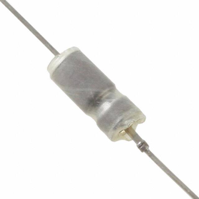
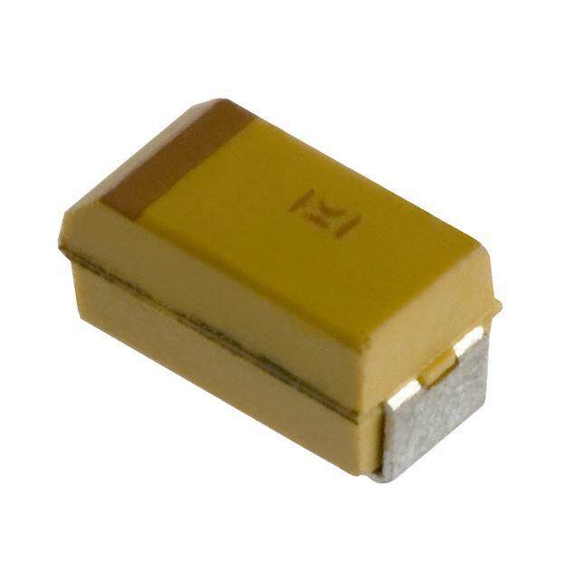
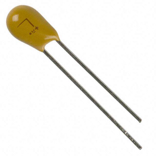
ICGOO电子元器件商城为您提供135D106X9050C6由Vishay设计生产,在icgoo商城现货销售,并且可以通过原厂、代理商等渠道进行代购。 135D106X9050C6价格参考。Vishay135D106X9050C6封装/规格:钽电容器, 10µF 密封 钽电容器 50V 轴向 6.4 欧姆。您可以下载135D106X9050C6参考资料、Datasheet数据手册功能说明书,资料中有135D106X9050C6 详细功能的应用电路图电压和使用方法及教程。
Vishay Sprague品牌的135D106X9050C6是一款钽电容器,属于表面贴装器件(SMD),具有高可靠性、低等效串联电阻(ESR)和稳定的电气性能。以下是该型号钽电容器的主要应用场景:

 1. 电源滤波
   - 用于开关电源、线性电源和直流-直流转换器中的输入/输出滤波。
   - 其高频率下的良好滤波特性可以有效抑制电源噪声,确保电路的稳定运行。

 2. 去耦应用
   - 在数字电路和模拟电路中作为去耦电容,消除高频噪声和电压波动。
   - 特别适用于微控制器(MCU)、数字信号处理器(DSP)和其他高速逻辑电路的电源引脚。

 3. 信号耦合与旁路
   - 用于音频放大器、射频(RF)电路和其他信号处理电路中的耦合或旁路功能。
   - 提供稳定的电容值,减少信号失真。

 4. 储能与能量释放
   - 在需要快速充放电的应用中(如脉冲电路、激光驱动器等),利用其低ESR特性实现高效能量传递。

 5. 工业与汽车电子
   - 应用于工业控制设备、逆变器、电机驱动器以及汽车电子系统(如发动机控制单元、信息娱乐系统等)。
   - 高可靠性和耐高温性能使其适合恶劣环境下的工作需求。

 6. 通信设备
   - 用于基站、路由器、交换机等通信设备中的电源管理和信号处理部分。
   - 支持高频率和高密度设计要求。

 7. 消费类电子产品
   - 在智能手机、平板电脑、笔记本电脑和其他便携式设备中,用于电源管理模块和音频电路。

 总结
Vishay Sprague 135D106X9050C6凭借其优异的电气特性和可靠性,广泛应用于各类电子设备中,特别是在对稳定性、小型化和高效能有较高要求的场景下表现突出。
| 参数 | 数值 |
| 产品目录 | |
| 描述 | CAP TANT 10UF 50V 10% AXIAL钽质电容器-湿式 50volts 10uF 10% C Case STD RANGE |
| ESR | 6.4 Ohms |
| ESR(等效串联电阻) | 6.4 欧姆 |
| 产品分类 | |
| 品牌 | Vishay / SpragueVishay Sprague |
| 产品手册 | |
| 产品图片 |
|
| rohs | 否含铅 / 不符合限制有害物质指令(RoHS)规范要求 |
| 产品系列 | 钽电容器,钽质电容器-湿式,Vishay / Sprague 135D106X9050C6135D |
| 数据手册 | |
| 产品型号 | 135D106X9050C6135D106X9050C6 |
| 不同温度时的使用寿命 | - |
| 产品 | Tantalum Wet Hermetically Sealed |
| 产品培训模块 | http://www.digikey.cn/PTM/IndividualPTM.page?site=cn&lang=zhs&ptm=11952http://www.digikey.cn/PTM/IndividualPTM.page?site=cn&lang=zhs&ptm=26235 |
| 产品目录绘图 |
|
| 产品目录页面 | |
| 产品种类 | 钽质电容器-湿式 |
| 其它名称 | 718-1255 |
| 制造商尺寸代码 | C |
| 制造商库存号 | C Case |
| 包装 | 托盘 |
| 商标 | Vishay / Sprague |
| 外壳直径 | 4.78 mm |
| 外壳长度 | 11.51 mm |
| 大小/尺寸 | 0.203" 直径 x 0.453" 长(5.16mm x 11.51mm) |
| 安装类型 | 通孔 |
| 容差 | ±10%10 % |
| 封装/外壳 | 轴向 |
| 工作温度 | -55°C ~ 200°C |
| 工作温度范围 | - 55 C to + 85 C |
| 引线间距 | - |
| 标准包装 | 1 |
| 漏泄电流 | 2 uA |
| 特性 | 液态钽 |
| 电压-额定 | 50V |
| 电压额定值 | 50 V |
| 电容 | 10 uF10µF |
| 端接类型 | Axial |
| 类型 | Wet Tantalum Capacitors Tantalum-Case with Glass-to-Tantalum Hermetic Seal密封 |
| 系列 | 135D |
| 纹波电流 | 715 mA |
| 高度-安装(最大值) | - |


- 商务部:美国ITC正式对集成电路等产品启动337调查
- 曝三星4nm工艺存在良率问题 高通将骁龙8 Gen1或转产台积电
- 太阳诱电将投资9.5亿元在常州建新厂生产MLCC 预计2023年完工
- 英特尔发布欧洲新工厂建设计划 深化IDM 2.0 战略
- 台积电先进制程称霸业界 有大客户加持明年业绩稳了
- 达到5530亿美元!SIA预计今年全球半导体销售额将创下新高
- 英特尔拟将自动驾驶子公司Mobileye上市 估值或超500亿美元
- 三星加码芯片和SET,合并消费电子和移动部门,撤换高东真等 CEO
- 三星电子宣布重大人事变动 还合并消费电子和移动部门
- 海关总署:前11个月进口集成电路产品价值2.52万亿元 增长14.8%

PDF Datasheet 数据手册内容提取
135D www.vishay.com Vishay Wet Tantalum Capacitors Tantalum-Case with Glass-to-Tantalum Hermetic Seal for -55 °C to +200 °C Operation FEATURES • Axial through-hole terminations: standard tin / lead (SnPb), 100 % tin (RoHS-compliant ) available Available • Standard and extended ratings • Model 135D tantalum-case electrolytic Available capacitors incorporate the advantages of all the varieties of electrolytic capacitors and eliminate most of the disadvantages. Thes e units have a 3 V reverse voltage capability at Available +85 °C and a higher ripple current capability than any other electrolytic type with similar combinations PERFORMANCE CHARACTERISTICS of capacitance and case size. • Designed for the aerospace applications, this capacitor Operating Temperature: -55 °C to +85 °C was developed under partial sponsorship of the Marshall (to +200 °C with voltage derating) Space Flight Center, National Aeronautics and Spac e Capacitance Tolerance: at 120 Hz, +25 °C Administration. The capacitors have a high resistance to ± 20 % standard. ± 10 %, ± 5 % available as special. damage from shock and vibration. Extended range ratings DC Leakage Current (DCL Max.): at +25 °C and above: and high temperature designs are available. leakage current shall not exceed the values listed in th e • Model 135D capacitors are commercial equivalents of Standard Ratings table. Tansitor style; AQ, AR, HAQ, HAR, Mallory-NACC Style; Life Test: capacitors are capable of withstanding a 2000 h TLT, TXT, THT, THX and Military Style CLR79 and CLR81, life test at a temperature of +85 °C or +125 °C at the designed to meet the performance requirements of applicable rated DC working voltage. Military Specification MIL-PRF-39006/22/25. Capacitors to meet MIL-PRF-39006/22/25 should be ordered by part Following life test: numbers shown in that specification. 1.DCL, measured at +85 °C rated voltage, shall not be in • Material categorization: for definitions of complianc e excess of the original requirement. please see www.vishay.com/doc?99912 2.The equivalent series resistance shall not exceed 150 % Note of the initial requirement. * This datasheet provides information about parts that are 3.Change in capacitance shall not exceed 10 % from the RoHS-compliant and / or parts that are non RoHS-compliant. For example, parts with lead (Pb) terminations are not RoHS-compliant. initial measurement. Please see the information / tables in this datasheet for details ORDERING INFORMATION 135D 306 X0 006 C 2 E3 MODEL CAPACITANCE CAPACITANCE DC VOLTAGE RATING CASE STYLE NUMBER RoHS- TOLERANCE AT +85 °C CODE COMPLIANT This is expressed X0 = ± 20 % This is expressed in See Standard temperature E3 = 100 % tin in picofarads. The X9 = ± 10 % volts. To complete the Ratings (max. +125 °C) termination first two digits are X5 = ± 5 % three-digit block, and 0 = no insulating sleeve (RoHS-compliant the significant zeros precede the Case 2 = polyester insulation sleeve design) figures. The third voltage rating. Codes 3 = high temperature Blank = SnPb is the number of table film insulation termination zeros to follow. (standard design) High temperature (max. +200 °C) 6 = high temperature film insulation 8 = no insulating sleeve Note • Packaging: the use of formed plastic trays for packaging these axial lead components is standard. Tape and reel is not available due to th e unit weight. Revision: 01-Mar-2019 1 Document Number: 40024 For technical questions, contact: tantalum@vishay.com THIS DOCUMENT IS SUBJECT TO CHANGE WITHOUT NOTICE. THE PRODUCTS DESCRIBED HEREIN AND THIS DOCUMENT ARE SUBJECT TO SPECIFIC DISCLAIMERS, SET FORTH AT www.vishay.com/doc?91000
135D www.vishay.com Vishay DIMENSIONS in inches [millimeters] Style CLR79 Tantalum feed-through Style CLR81 0.078 [1.98] max. dia. Term. loc. within 0.250 [6.35] 0.031 [0.79] R Terminal max. of true position - + welded to case D dia. Case 0.094 [2.38] Circuit diagram max. Exwteerldnal 0.025 ± 0.002 Glass [0.64 ± 0.05] E L E Insulating sleeve BARE CASE WITH INSULATING SLEEVE WEIGHT E CASE CODE (oz. / g) D L D (MAX.) L (1) LEAD LENGTH (Max.) 0.188 ± 0.016 0.453 + 0.031 / - 0.016 0.219 0.565 1.500 ± 0.250 0.09 C [4.78 ± 0.41] [11.51 + 0.79 / - 0.41] [5.56] [14.35] [38.10 ± 6.35] [2.6] 0.281 ± 0.016 0.641 + 0.031 / -0.016 0.312 0.785 2.250 ± 0.250 0.22 F [7.14 ± 0.41] [16.28 + 0.79 / -0.41] [7.92] [19.94] [57.15 ± 6.35] [6.2] 0.375 ± 0.016 0.766 + 0.031 / - 0.016 0.406 0.95 2.250 ± 0.250 0.41 T [9.53 ± 0.41] [19.46 + 0.79 / - 0.41] [10.31] [24.13] [57.15 ± 6.35] [11.6] 0.375 ± 0.016 1.062 + 0.031 / - 0.016 0.406 1.31 2.250 ± 0.250 0.62 K [9.53 ± 0.41] [26.97 + 0.79 / - 0.41] [10.31] [33.27] [57.15 ± 6.35] [17.7] Note (1) Typical length, for reference only STANDARD RATINGS MAX. DCL MAX. CAPACITANCE MAX. MAX. ESR MAX. IMP. (μA) AT CHANGE (%) AT RIPPLE CAPACITANCE CASE AT +25 °C AT -55 °C PART NUMBER (1) 40 kHz (μF) CODE 12(0 H) z 12(0 H) z +25 °C ++18255 ° °CC -55 °C +85 °C +125 °C IRMS (mA) 6 V AT +85 °C; 4 V AT +125 °C; 3.6 V AT +200 °C DC DC DC 30 C 135D306X0006C2 4.0 100 1.0 2.0 -40 +10.5 +12 820 68 C 135D686X0006C2 3.2 60 1.0 2.0 -40 +14 +16 960 140 F 135D147X0006F2 2.0 40 1.0 3.0 -40 +14 +16 1200 270 F 135D277X0006F2 2.2 25 1.0 6.5 -44 +17.5 +20 1375 330 T 135D337X0006T2 1.4 20 2.0 7.9 -44 +14 +16 1800 560 T 135D567X0006T2 1.3 25 2.0 13.0 -64 +17.5 +20 1900 1200 K 135D128X0006K2 1.0 20 3.0 14.0 -80 +25 +25 2265 8 V AT +85 °C; 5 V AT +125 °C; 4.8 V AT +200 °C DC DC DC 25 C 135D256X0008C2 4.0 100 1.0 2.0 -40 +10.5 +12 820 56 C 135D566X0008C2 3.3 59 1.0 2.0 -40 +14 +16 900 120 F 135D127X0008F2 2.6 50 1.0 2.0 -44 +17.5 +20 1230 220 F 135D227X0008F2 2.4 30 1.0 7.0 -44 +17.5 +20 1370 290 T 135D297X0008T2 1.8 25 2.0 6.0 -64 +17.5 +20 1770 430 T 135D437X0008T2 1.4 25 2.0 14.0 -64 +17.5 +20 1825 850 K 135D857X0008K2 1.0 22 4.0 16.0 -80 +25 +25 2330 10 V AT +85 °C; 7 V AT +125 °C; 6 V AT +200 °C DC DC DC 20 C 135D206X0010C2 4.0 120 1.0 2.0 -32 +10.5 +12 820 47 C 135D476X0010C2 3.7 90 1.0 2.0 -36 +14 +16 855 100 F 135D107X0010F2 2.4 60 1.0 4.0 -36 +14 +16 1200 180 F 135D187X0010F2 2.2 40 1.0 7.0 -36 +14 +16 1365 250 T 135D257X0010T2 1.8 30 2.0 10.0 -40 +14 +16 1720 390 T 135D397X0010T2 1.5 25 2.0 16.0 -64 +17.5 +20 1800 750 K 135D757X0010K2 1.0 23 4.0 16.0 -80 +25 +25 2360 Note (1) Part numbers are for units with ± 20 % capacitance tolerance, standard +125 °C maximum temperature, standard polyesterfilm insulation, and tin-lead terminations. For other capacitance tolerances, other maximum temperatures, insulation and termination options, please consult Ordering Information on first page for proper part number. Revision: 01-Mar-2019 2 Document Number: 40024 For technical questions, contact: tantalum@vishay.com THIS DOCUMENT IS SUBJECT TO CHANGE WITHOUT NOTICE. THE PRODUCTS DESCRIBED HEREIN AND THIS DOCUMENT ARE SUBJECT TO SPECIFIC DISCLAIMERS, SET FORTH AT www.vishay.com/doc?91000
135D www.vishay.com Vishay STANDARD RATINGS MAX. DCL MAX. CAPACITANCE MAX. MAX. ESR MAX. IMP. (μA) AT CHANGE (%) AT RIPPLE CAPACITANCE CASE AT +25 °C AT -55 °C PART NUMBER (1) 40 kHz (μF) CODE 12(0 H) z 12(0 H) z +25 °C ++18255 ° °CC -55 °C +85 °C +125 °C IRMS (mA) 15 V AT +85 °C; 10 V AT +125 °C; 9 V AT +200 °C DC DC DC 15 C 135D156X0015C2 4.4 155 1.0 2.0 -24 +10.5 +12 780 33 C 135D336X0015C2 4.0 90 1.0 2.0 -28 +14 +16 820 70 F 135D706X0015F2 2.8 75 1.0 4.0 -28 +14 +16 1150 120 F 135D127X0015F2 2.6 50 1.0 7.0 -28 +17.5 +20 1450 170 T 135D177X0015T2 2.4 35 2.0 10.0 -32 +14 +16 1480 270 T 135D277X0015T2 2.2 30 2.0 16.0 -56 +17.5 +20 1740 540 K 135D547X0015K2 1.0 23 6.0 24.0 -80 +25 +25 2330 25 V AT +85 °C; 15 V AT +125 °C; 12 V AT +200 °C DC DC DC 10 C 135D106X0025C2 5.3 220 1.0 2.0 -16 +8 +9 715 22 C 135D226X0025C2 4.2 140 1.0 2.0 -20 +10.5 +12 800 50 F 135D506X0025F2 3.0 70 1.0 2.0 -28 +13 +15 1130 100 F 135D107X0025F2 2.8 50 1.0 10.0 -28 +13 +15 1435 120 T 135D127X0025T2 2.6 38 2.0 6.0 -32 +13 +15 1450 180 T 135D187X0025T2 2.2 32 2.0 18.0 -48 +13 +15 1525 350 K 135D357X0025K2 1.3 24 7.0 28.0 -70 +25 +25 1970 30 V AT +85 °C; 20 V AT +125 °C; 18 V AT +200 °C DC DC DC 8 C 135D805X0030C2 6.6 275 1.0 2.0 -16 +8 +12 640 15 C 135D156X0030C2 6.2 175 1.0 2.0 -20 +10.5 +12 780 22 F 135D226X0030F2 4.6 95 1.0 5.0 -20 +10.5 +12 1005 40 F 135D406X0030F2 4.0 65 1.0 5.0 -24 +10.5 +12 1120 68 F 135D686X0030F2 2.9 60 1.0 8.0 -24 +13 +15 1285 100 T 135D107X0030T2 2.7 40 2.0 12.0 -28 +10.5 +12 1450 150 T 135D157X0030T2 2.3 35 2.0 18.0 -48 +13 +15 1525 300 K 135D307X0030K2 1.4 25 8.0 32.0 -60 +25 +25 1950 35 V AT +85 °C; 22 V AT +125 °C; 21 V AT +200 °C DC DC DC 15 C 135D156X0035C2 6.2 175 0.75 1.5 -20 +10.5 +12 660 68 F 135D686X0035F2 2.9 60 1.0 2.0 -24 +13 +15 1195 270 K 135D277X0035K2 1.4 26 3.0 12.0 -58 +25 +25 1950 50 V AT +85 °C; 30 V AT +125 °C; 30 V AT +200 °C DC DC DC 5 C 135D505X0050C2 8.0 400 1.0 2.0 -16 +5 +6 580 10 C 135D106X0050C2 6.4 250 1.0 2.0 -24 +8 +9 715 25 F 135D256X0050F2 4.6 95 1.0 5.0 -20 +10.5 +12 1005 47 F 135D476X0050F2 3.7 70 1.0 9.0 -28 +13 +15 1155 60 T 135D606X0050T2 2.9 45 2.0 12.0 -16 +10.5 +12 1335 82 T 135D826X0050T2 2.5 45 2.0 16.0 -32 +13 +15 1400 160 K 135D167X0050K2 1.5 27 8.0 32.0 -50 +25 +25 1900 60 V AT +85 °C; 40 V AT +125 °C; 36 V AT +200 °C DC DC DC 4 C 135D405X0060C2 9.3 550 1.0 2.0 -16 +5 +6 525 8.2 C 135D825X0060C2 6.6 275 1.0 2.0 -24 +8 +9 625 20 F 135D206X0060F2 4.7 105 1.0 5.0 -16 +8 +9 930 39 F 135D396X0060F2 3.4 90 1.0 9.0 -28 +10.5 +15 1110 50 T 135D506X0060T2 2.9 50 2.0 12.0 -16 +10.5 +12 1330 68 T 135D686X0060T2 2.5 50 2.0 16.0 -32 +10.5 +15 1365 140 K 135D147X0060K2 1.5 28 8.0 32.0 -40 +20 +20 1850 75 V AT +85 °C; 50 V AT +125 °C; 45 V AT +200 °C DC DC DC 3.5 C 135D355X0075C2 9.5 650 1.0 2.0 -16 +5 +6 525 6.8 C 135D685X0075C2 6.8 300 1.0 2.0 -20 +8 +9 610 15 F 135D156X0075F2 5.3 150 1.0 5.0 -16 +8 +9 890 33 F 135D336X0075F2 4.2 90 1.0 10.0 -24 +10.5 +15 1000 40 T 135D406X0075T2 3.0 60 2.0 12.0 -16 +10.5 +12 1250 56 T 135D566X0075T2 2.6 60 2.0 17.0 -28 +10.5 +15 1335 Note (1) Part numbers are for units with ± 20 % capacitance tolerance, standard +125 °C maximum temperature, standard polyesterfilm insulation, and tin-lead terminations. For other capacitance tolerances, other maximum temperatures, insulation and termination options, please consult Ordering Information on first page for proper part number. Revision: 01-Mar-2019 3 Document Number: 40024 For technical questions, contact: tantalum@vishay.com THIS DOCUMENT IS SUBJECT TO CHANGE WITHOUT NOTICE. THE PRODUCTS DESCRIBED HEREIN AND THIS DOCUMENT ARE SUBJECT TO SPECIFIC DISCLAIMERS, SET FORTH AT www.vishay.com/doc?91000
135D www.vishay.com Vishay STANDARD RATINGS MAX. DCL MAX. CAPACITANCE MAX. MAX. ESR MAX. IMP. (μA) AT CHANGE (%) AT RIPPLE CAPACITANCE CASE AT +25 °C AT -55 °C PART NUMBER (1) 40 kHz (μF) CODE 12(0 H) z 12(0 H) z +25 °C ++18255 ° °CC -55 °C +85 °C +125 °C IRMS (mA) 110 K 135D117X0075K2 1.5 29 9.0 36.0 -35 +20 +20 1850 100 V AT +85 °C; 65 V AT +125 °C; 60 V AT +200 °C DC DC DC 2.2 C 135D225X0100C2 10.6 950 1.0 2.0 -16 +7 +8 505 2.5 C 135D255X0100C2 10.6 950 1.0 2.0 -16 +7 +8 505 3.9 C 135D395X0100C2 10.0 600 1.0 2.0 -16 +7 +8 520 4.7 C 135D475X0100C2 8.5 500 1.0 2.0 -16 +7 +8 565 11 F 135D116X0100F2 6.0 200 1.0 4.0 -16 +7 +8 835 22 F 135D226X0100F2 4.8 100 1.0 9.0 -16 +7 +8 965 30 T 135D306X0100T2 3.3 80 2.0 12.0 -16 +7 +8 1240 43 T 135D436X0100T2 2.6 70 2.0 17.0 -20 +7 +8 1335 82 K 135D826X0100K2 1.6 39 3.0 24 -24 +18 +18 1860 86 K 135D866X0100K2 1.6 30 9.0 36.0 -25 +15 +15 1800 125 V AT +85 °C; 85 V AT +125 °C; 75 V AT +200 °C DC DC DC 1.7 C 135D175X0125C2 15.6 1250 1.0 2.0 -16 +7 +8 415 3.6 C 135D365X0125C2 10.0 600 1.0 2.0 -16 +7 +8 520 9 F 135D905X0125F2 7.4 240 1.0 5.0 -16 +7 +8 755 14 F 135D146X0125F2 5.7 167 1.0 7.0 -16 +7 +8 860 18 T 135D186X0125T2 3.7 129 2.0 9.0 -16 +7 +8 1130 25 T 135D256X0125T2 3.2 93 2.0 13.0 -16 +7 +8 1200 56 K 135D566X0125K2 1.6 32 10.0 40.0 -25 +15 +15 1800 Note (1) Part numbers are for units with ± 20 % capacitance tolerance, standard +125 °C maximum temperature, standard polyesterfilm insulation, and tin-lead terminations. For other capacitance tolerances, other maximum temperatures, insulation and termination options, please consult Ordering Information on first page for proper part number. EXTENDED RATINGS MAX. DCL MAX. CAPACITANCE MAX. MAX. ESR MAX. IMP. (μA) AT CHANGE (%) AT RIPPLE CAPACITANCE AT +25 °C AT -55 °C CASE CODE PART NUMBER (1) 40 kHz (μF) 12(0 H) z 12(0 H) z +25 °C ++18255 ° °CC -55 °C +85 °C +125 °C (ImRMAS) 6 V AT +85 °C; 4 V AT +125 °C; 3.6 V AT +200 °C DC DC DC 220 C 135D227X0006C2 3.0 36 2.0 9.0 -64 +13 +16 1000 560 F 135D567X0006F2 2.5 21 3.0 9.0 -77 +16 +20 1500 820 F 135D827X0006F2 2.5 18 3.0 14 -88 +16 +20 1500 1200 T 135D128X0006T2 1.5 18 5.0 18.0 -88 +20 +25 1900 1500 T 135D158X0006T2 1.5 18 5.0 20.0 -90 +20 +25 1900 2200 K 135D228X0006K2 1.0 13 6.0 24.0 -90 +25 +30 2300 8 V AT +85 °C; 5 V AT +125 °C; 4.8 V AT +200 °C DC DC DC 180 C 135D187X0008C2 3.0 45 2.0 9.0 -60 +13 +16 1000 680 F 135D687X0008F2 2.5 22 3.0 14.0 -83 +16 +20 1500 1500 T 135D158X0008T2 1.5 18 5.0 20.0 -90 +20 +25 1900 1800 K 135D188X0008K2 1.0 14 7.0 25.0 -90 +25 +30 2300 10 V AT +85 °C; 7 V AT +125 °C; 6 V AT +200 °C DC DC DC 120 C 135D127X0010C2 3.2 54 2.0 6.0 -40 +14 +16 900 150 C 135D157X0010C2 3.0 54 2.0 9.0 -55 +13 +16 900 390 F 135D397X0010F2 2.5 27 3.0 9.0 -66 +16 +20 1470 470 F 135D477X0010F2 2.5 27 3.0 16.0 -66 +16 +20 1450 560 F 135D567X0010F2 2.5 27 3.0 16.0 -77 +16 +20 1450 1200 T 135D128X0010T2 1.5 18 5.0 20.0 -88 +20 +25 1850 Note (1) Part numbers are for units with ± 20 % capacitance tolerance, standard +125 °C maximum temperature, standard polyesterfilm insulation, and tin-lead terminations. For other capacitance tolerances, other maximum temperatures, insulation and termination options, please consult Ordering Information on first page for proper part number. Revision: 01-Mar-2019 4 Document Number: 40024 For technical questions, contact: tantalum@vishay.com THIS DOCUMENT IS SUBJECT TO CHANGE WITHOUT NOTICE. THE PRODUCTS DESCRIBED HEREIN AND THIS DOCUMENT ARE SUBJECT TO SPECIFIC DISCLAIMERS, SET FORTH AT www.vishay.com/doc?91000
135D www.vishay.com Vishay EXTENDED RATINGS MAX. DCL MAX. CAPACITANCE MAX. MAX. ESR MAX. IMP. (μA) AT CHANGE (%) AT RIPPLE CAPACITANCE AT +25 °C AT -55 °C CASE CODE PART NUMBER (1) 40 kHz (μF) 12(0 H) z 12(0 H) z +25 °C ++18255 ° °CC -55 °C +85 °C +125 °C (ImRMAS) 1500 K 135D158X0010K2 1.0 15 7.0 25.0 -88 +25 +30 2300 15 V AT +85 °C; 10 V AT +125 °C; 9 V AT +200 °C DC DC DC 82 C 135D826X0015C2 3.9 72 2.0 6.0 -35 +12 +16 900 100 C 135D107X0015C2 3.9 72 2.0 9.0 -44 +13 +16 900 270 F 135D277X0015F2 2.5 31 3.0 9.0 -62 +16 +15 1450 390 F 135D397X0015F2 2.5 31 3.0 16.0 -66 +16 +20 1450 680 T 135D687X0015T2 1.8 22 6.0 18.0 -74 +20 +25 1800 820 T 135D827X0015T2 1.8 22 6.0 24.0 -77 +20 +25 1800 1000 K 135D108X0015K2 1.2 17 8.0 32.0 -77 +25 +30 2330 25 V AT +85 °C; 15 V AT +125 °C; 12 V AT +200 °C DC DC DC 47 C 135D476X0025C2 5.2 100 2.0 6.0 -23 +12 +15 800 56 C 135D566X0025C2 4.3 90 2.0 6.0 -25 +12 +15 850 68 C 135D686X0025C2 4.3 90 2.0 9.0 -40 +12 +15 850 180 F 135D187X0025F2 2.7 33 3.0 9.0 -54 +13 +15 1400 270 F 135D277X0025F2 2.7 33 3.0 16.0 -62 +13 +16 1400 390 T 135D397X0025T2 1.8 25 6.0 18.0 -55 +18 +25 1500 470 T 135D477X0025T2 1.8 24 6.0 18.0 -65 +18 +25 1750 560 T 135D567X0025T2 1.8 24 7.0 28.0 -72 +20 +25 1750 680 K 135D687X0025K2 1.2 19 8.0 32.0 -72 +25 +30 2100 820 K 135D827X0025K2 1.3 26 8.0 32.0 -80 +25 +25 2100 30 V AT +85 °C; 20 V AT +125 °C; 18 V AT +200 °C DC DC DC 47 C 135D476X0030C2 5.2 100 2.0 6.0 -23 +12 +15 800 56 C 135D566X0030C2 5.2 100 2.0 9.0 -38 +12 +15 800 150 F 135D157X0030F2 2.5 36 3.0 9.0 -42 +13 +15 1200 220 F 135D227X0030F2 2.5 36 3.0 16.0 -60 +13 +16 1200 300 T 135D307X0030T2 2.2 44 3.0 12.0 -60 +15 +15 1559 390 T 135D397X0030T2 1.8 25 6.0 18.0 -55 +18 +25 1500 470 T 135D477X0030T2 1.8 25 8.0 32.0 -65 +20 +25 1500 560 K 135D567X0030K2 1.3 20 9.0 36.0 -65 +25 +30 2000 35 V AT +85 °C; 22 V AT +125 °C; 21 V AT +200 °C DC DC DC 39 C 135D396X0035C2 4.1 61 2.0 6.0 -22 +12 +14 820 120 F 135D127X0035F2 2.5 31 3.0 10.0 -40 +13 +15 1315 330 T 135D337X0035T2 1.8 20 6.0 18.0 -50 +16 +25 1640 370 K 135D377X0035K2 1.3 15 9.0 36.0 -60 +25 +30 2040 40 V AT +85 °C; 25 V AT +125 °C; 20 V AT +200 °C DC DC DC 39 C 135D396X0040C2 4.1 61 2.0 6.0 -22 +12 +14 820 220 K 135D227X0040K2 1.6 27 3.0 22.0 -58 +23 +23 1900 370 K 135D377X0040K2 1.5 30 5.0 25.0 -75 +25 +25 1900 470 K 135D477X0040K2 1.3 30 9.0 35.0 -80 +25 +25 2040 50 V AT +85 °C; 30 V AT +125 °C; 30 V AT +200 °C DC DC DC 33 C 135D336X0050C2 5.0 135 2.0 9.0 -29 +10 +12 700 100 F 135D107X0050F2 2.8 49 4.0 12.0 -36 +13 +15 1200 120 F 135D127X0050F2 2.5 49 4.0 24.0 -42 +12 +15 1200 270 T 135D277X0050T2 2.0 30 8.0 32.0 -46 +20 +25 1450 Note (1) Part numbers are for units with ± 20 % capacitance tolerance, standard +125 °C maximum temperature, standard polyesterfilm insulation, and tin-lead terminations. For other capacitance tolerances, other maximum temperatures, insulation and termination options, please consult Ordering Information on first page for proper part number. Revision: 01-Mar-2019 5 Document Number: 40024 For technical questions, contact: tantalum@vishay.com THIS DOCUMENT IS SUBJECT TO CHANGE WITHOUT NOTICE. THE PRODUCTS DESCRIBED HEREIN AND THIS DOCUMENT ARE SUBJECT TO SPECIFIC DISCLAIMERS, SET FORTH AT www.vishay.com/doc?91000
135D www.vishay.com Vishay EXTENDED RATINGS MAX. DCL MAX. CAPACITANCE MAX. MAX. ESR MAX. IMP. (μA) AT CHANGE (%) AT RIPPLE CAPACITANCE AT +25 °C AT -55 °C CASE CODE PART NUMBER (1) 40 kHz (μF) 12(0 H) z 12(0 H) z +25 °C ++18255 ° °CC -55 °C +85 °C +125 °C (ImRMAS) 330 K 135D337X0050K2 1.5 30 9.0 36.0 -46 +25 +30 1900 60 V AT +85 °C; 40 V AT +125 °C; 36 V AT +200 °C DC DC DC 18 C 135D186X0060C2 7.0 160 2.0 12.0 -20 +7 +8 700 27 C 135D276X0060C2 5.0 144 3.0 12.0 -24 +10 +12 700 82 F 135D826X0060F2 2.9 54 4.0 16.0 -30 +15 +15 1100 100 F 135D107X0060F2 2.5 54 4.0 20.0 -36 +12 +15 1100 220 T 135D227X0060T2 1.8 29 8.0 32.0 -40 +16 +20 1400 270 K 135D277X0060K2 1.4 23 9.0 36.0 -45 +20 +25 1850 330 K 135D337X0060K2 1.3 31 10.0 40.0 -72 +25 +25 1850 63 V AT +85 °C; 40 V AT +125 °C; 31 V AT +200 °C DC DC DC 10 C 135D106X0063C2 5.3 250 1.0 2.0 -20 +8 +9 715 27 C 135D276X0063C2 5.0 144 3.0 12.0 -24 +10 +12 700 100 F 135D107X0063F2 2.5 54 2.0 12.0 -36 +12 +15 1100 75 V AT +85 °C; 50 V AT +125 °C; 45 V AT +200 °C DC DC DC 5.6 C 135D565X0075C2 14.2 475 2.0 5.0 -17 +8 +8 600 12 C 135D126X0075C2 5.1 157 3.0 12.0 -19 +10 +12 600 22 C 135D226X0075C2 5.1 157 3.0 12.0 -19 +10 +12 600 68 F 135D686X0075F2 3.0 63 4.0 16.0 -25 +12 +15 1000 82 F 135D826X0075F2 2.5 63 4.0 24.0 -30 +12 +15 1000 110 F 135D117X0075F2 2.5 54 4.0 20.0 -36 +12 +15 1100 180 T 135D187X0075T2 2.2 30 9.0 36.0 -35 +16 +20 1300 200 K 135D207X0075K2 18 24 10.0 40.0 -40 +20 +25 1800 220 K 135D227X0075K2 1.8 24 10.0 40.0 -40 +20 +25 1800 300 K 135D307X0075K2 1.8 32 12.0 48.0 -60 +22 +22 2000 100 V AT +85 °C; 65 V AT +125 °C; 60 V AT +200 °C DC DC DC 5.6 C 135D565X0100C2 14 475 2.0 5.0 -17 +8 +8 565 10 C 135D106X0100C2 5.9 200 3.0 12.0 -17 +10 +12 800 39 F 135D396X0100F2 3.5 80 5.0 24.0 -20 +12 +15 1300 47 T 135D476X0100T2 2.5 70 2.0 10.0 -23 +10 +10 1390 56 T 135D566X0100T2 2.4 50 5.0 20.0 -25 +12 +12 1400 68 T 135D686X0100T2 2.2 40 10.0 40.0 -30 +14 +16 1600 120 K 135D127X0100K2 2.7 30 12.0 48.0 -35 +15 +17 2000 125 V AT +85 °C; 85 V AT +125 °C; 75 V AT +200 °C DC DC DC 3.9 C 135D395X0125C2 20.4 557 2.0 5.0 -16 +7 +8 495 6.8 C 135D685X0125C2 11.7 300 3.0 12.0 -14 +10 +12 700 15 F 135D156X0125F2 5.3 167 1.0 7.0 -16 +7 +8 1200 27 F 135D276X0125F2 3.5 90 5.0 24.0 -18 +12 +15 1200 47 T 135D476X0125T2 2.2 50 10.0 40.0 -26 +14 +16 1500 56 T 135D566X0125T2 2.2 50 10.0 40.0 -26 +14 +16 1500 68 K 135D686X0125K2 2.2 32 11.0 44.0 -28 +15 +16 1850 82 K 135D826X0125K2 2.8 32 12.0 48.0 -30 +15 +17 1900 Note (1) Part numbers are for units with ± 20 % capacitance tolerance, standard +125 °C maximum temperature, standard polyesterfilm insulation, and tin-lead terminations. For other capacitance tolerances, other maximum temperatures, insulation and termination options, please consult Ordering Information on first page for proper part number. Revision: 01-Mar-2019 6 Document Number: 40024 For technical questions, contact: tantalum@vishay.com THIS DOCUMENT IS SUBJECT TO CHANGE WITHOUT NOTICE. THE PRODUCTS DESCRIBED HEREIN AND THIS DOCUMENT ARE SUBJECT TO SPECIFIC DISCLAIMERS, SET FORTH AT www.vishay.com/doc?91000
135D www.vishay.com Vishay TYPICAL CURVES OF IMPEDANCE AS A FUNCTION OF FREQUENCY AT VARIOUS TEMPERATURES “C” Case 33 μF, 50 V Capacitors “K” Case 56 μF, 125 V Capacitors 100 100 Ω) 10 Ω) 10 Impedance ( 1.0 -- 45- 052 0°°CC °C Impedance ( 1.0 --- 425005 °°°CCC + 25 °C + 125 °C + 85 °C + 125 °C + 25 °C + 85 °C 0.1 0.1 100 1K 10K 100K 1M 10M 100 1K 10K 100K 1M 10M Frequency (Hz) Frequency (Hz) PERFORMANCE CHARACTERISTICS 1. Operating Temperature: capacitors are designed to 3.2 Surge Voltage Test: capacitors shall withstand the operate over a temperature range of -55 °C to +200 °C. surge voltage applied through a 1000 ± 10 % resistor in series with the capacitor and voltage source at the UP TO AT AT rate of one-half minute on, four and one-half minute s +85 °C +125 °C +200 °C off, for 1000 successive test cycles at +85 °C or (V) (V) (V) +125 °C. 6 4 3.6 3.3 Following the surge voltage test, the capacitance at 8 5 4.8 +25 °C shall not have changed by more than ± 10 % and 10 7 6 the equivalent series resistance and DC leakage curren t will not exceed the values shown in the Standard 15 10 9 Ratings table for each capacitor. 25 15 12 4. Capacitance Tolerance: the capacitance of all 30 20 18 capacitors shall be within the specified tolerance limits 35 22 21 of the nominal rating. 40 25 20 4.1 Measurements shall be made by the bridge method a t or referred to a frequency of 120 Hz at a temperature of 50 30 30 +25 °C. The maximum voltage applied to the capacitors 60 40 36 during measurement shall be 1 V . Measurement RMS 63 40 31 accuracy of the bridge shall be within ± 2 %. 75 50 45 5. Capacitance Change With Temperature: the capacitance change with temperature shall not exceed 100 65 60 the values given in the Standard Ratings table for eac h 125 85 75 capacitor. 2. DC Working Voltage: the DC working voltage is th e 6. Equivalent Series Resistance: measurements shall be maximum operating voltage for continuous duty at the made by the bridge method at, or referred to, a rated temperature. frequency of 120 Hz at a temperature of +25 °C. A 3. Surge Voltage: the surge voltage rating is the maximum maximum of 1 V shall be applied durin g RMS voltage to which the capacitors should be subjecte d measurement. under any conditions. This includes transients and pea k 6.1 The equivalent series resistance shall not exceed the ripple at the highest line voltage. maximum value in ohms listed in the Standard Rating s 3.1 The surge voltage of capacitors is 115 % of rated D C table for each capacitor. working voltage. Revision: 01-Mar-2019 7 Document Number: 40024 For technical questions, contact: tantalum@vishay.com THIS DOCUMENT IS SUBJECT TO CHANGE WITHOUT NOTICE. THE PRODUCTS DESCRIBED HEREIN AND THIS DOCUMENT ARE SUBJECT TO SPECIFIC DISCLAIMERS, SET FORTH AT www.vishay.com/doc?91000
135D www.vishay.com Vishay 6.2 The dissipation factor may be calculated from the TYPICAL LEAKAGE CURRENT FACTOR equivalent series resistance and capacitance values as RANGE shown: 2fRC DF = ------------------ 1.0 4 10 0.9 where: 0.8 0.7 DF = dissipation Factor in % 0.6 R = ESR in 0.5 C = capacitance in μF 0.4 f = frequency in Hz At 120 Hz, the above equation becomes: 0.3 R x C R DF = --------------- O 13.26 T 0.2 C A F For example, percent dissipation factor of a 30 μF, 6 V T N capacitor, which has a maximum ESR of 4.0 at E +25 °C and 120 Hz, would be calculated as shown: RR 0.1 U C 0.09 DF = 2-------- -x--- --1---2----0--- --x--- -4---- --x-- --3----0-- = 4---- --x-- --3----0-- = 9.05 % E 0.08 4 13.26 G 10 A 0.07 7. Leakage Current: measurements shall be made at the AK 0.06 E applicable rated working voltage at +25 °C ± 5 ° C L 0.05 through application of a steady source of power, such 0.04 as a regulated power supply. A 1000 resistor to limi t the charging current shall be connected in series wit h 0.03 each capacitor under test. Rated working voltage shall be applied to capacitors for 5 minutes before making 0.02 leakage current measurements. 7.1 The maximum leakage current for any capacitor shall not exceed the maximum value in microamperes listed 0.01 in the Standard Ratings and Extended Ratings table fo r each capacitor. 0 10 20 30 40 50 60 70 80 90 100 Note PERCENT OF RATED VOLTAGE • Leakage current varies with applied voltage. See graph next column for the appropriate adjustment factor 9.3 Capacitors are capable of withstanding life test at th e 8. Low Temperature Impedance: the impedance of any following conditions: capacitor at -55 °C at 120 Hz, shall not exceed the values given in the Standard Ratings and Extende d TEMPERATURE HOURS % RATED VOLTAGE Ratings tables. +175 °C 2000 50 9. Life Test: capacitors are capable of withstanding a +175 °C 300 65 2000 h life test at a temperature of +85 °C or +125 °C at +200 °C 300 60 the applicable rated DC working voltage. 9.1 Following the life test, the capacitors shall be returne d 9.4 Following the life test, the capacitors shall be returned to 25 °C ± 5 °C. The leakage current, measured at the to +25 °C ± 5 °C. The leakage current, at the rated +85 °C rated voltage, shall not be in excess of the voltage shall not exceed 200 % of the original original requirement; the capacitance value shall not requirement or 10 μA, whichever is greater; the exceed 150 % of the initial requirement; the equivalent series resistance shall not be greater than capacitance value shall not change more than 10 % 200 % of the original requirement; the capacitance from the initial measurement. value shall not increase by more than 10 % or decrease by more than 20 % from the initial measurement. Revision: 01-Mar-2019 8 Document Number: 40024 For technical questions, contact: tantalum@vishay.com THIS DOCUMENT IS SUBJECT TO CHANGE WITHOUT NOTICE. THE PRODUCTS DESCRIBED HEREIN AND THIS DOCUMENT ARE SUBJECT TO SPECIFIC DISCLAIMERS, SET FORTH AT www.vishay.com/doc?91000
135D www.vishay.com Vishay 10. Ripple Life Test at +85 °C: capacitors shall be tested 14. Random Vibration: capacitors shall withstand in accordance with Military Specificatio n random vibration at all levels up to 51 g RMS overall MIL-PRF-39006 except that: when tested in accordance with MIL-STD-202, a) Operation conditions: this test shall be run at a method 214, test condition II K. The test shall be frequency of 40 kHz ± 2 kHz sinusoidal and at th e conducted for 1.5 h in each of three mutually RMS ripple current levels specified in the Standard perpendicular directions. Ratings and Extended Ratings table. 14.1 Electrical measurements made during the test shall b) Applied DC voltage shall be reduced so that the show no intermittent contacts, open circuits or short peak AC voltage plus DC voltage shall not exceed circuits. the rated voltage of the capacitor in either the 15. Pull Test: leads shall withstand a tensile stress of 3 forward or reverse direction. lbs. (1.4 kg) for 30 s applied axially in accordance wit h 10.1 When tested as specified above, capacitors shall meet MIL-STD-202, method 211, test condition A. the following requirements: 16. Lead Bend Test: leads shall meet the bend test a) The DC leakage current at +25 °C and at +85 ° C specified in Military Standard MIL-STD-202, method shall not exceed the original requirements. 211 A, condition C except that the number of bend s shall be 4. b) The capacitance shall not change more than ± 15 % from the initial measured value. 17. Moisture Resistance: capacitors shall withstand the moisture resistance cycling test specified in Military c) The dissipation factor shall not exceed the original Standard MIL-STD-202, method 106, without requirements. departure from the original limits of capacitance, d) Visual examination: there shall be no damage, equivalent series resistance and DC leakage current. obliteration of marking or leakage of electrolyte. 18. Reduced Pressure: capacitors shall be stabilized at a 11. Reverse Voltage Test: capacitors shall withstand a reduced atmospheric pressure of 0.82" [20.83 mm] of reverse voltage of 3 V at +85 °C or 2 V at +125 ° C mercury for a period of 5 min. Rated DC voltage shall DC for 2000 h. The capacitors shall then be restabilized for be applied for 1 min. Capacitors shall not flash over 24 h at 85 °C with rated DC forward potential applie d nor shall end seals be damaged by this nor should th e through a 1000 resistor. capacitors be electrically effected insofar as 11.1 Following the reverse voltage test, the DC leakage capacitance, equivalent series resistance or leakage current shall not be in excess of the original current is concerned. requirement; the equivalent series resistance shall not 19. Seal Test: exceed 200 % of the initial requirement; the 19.1 Capacitors shall be tested in accordance wit h capacitance value shall not be less than 90 % of th e MIL-STD-202, method 112, test condition C, initial measurement. procedure IIIa. Specimens shall be pressurized at 4 12. Mechanical Shock Test: capacitors shall withstand a atmospheres (gage) for 4 h. shock of 500 g when tested in accordance wit h 20. Thermal Shock: capacitors shall be subjected to 30 0 method 213 of MIL-STD-202, test condition D. cycles of thermal shock in accordance with Military 12.1 Following the mechanical shock test, capacitors shall specification MIL-PRF-39006. be examined for evidence of mechanical damage an d 20.1 Following the thermal shock test, capacitor leakag e leakage of electrolyte. Capacitance, equivalent series current shall not exceed twice the initial requirement. resistance, and DC leakage current shall meet the 21. Marking: capacitors shall be marked with Vishay initial requirements. identification; capacitors type (135D); rated 13. High Frequency Vibration: capacitors shall withstand capacitance and tolerance (the tolerance shall b e vibration from 10 Hz to 2000 Hz at 80 g without internal coded, using the list shown in How to Order); rated DC damage when tested in accordance wit h working voltage at +85 °C; the standard EIA date MIL-STD-202, method 204, test condition H. Electrical code of manufacture. measurements made while under these conditions 21.1 Polarity shall be indicated by plus signs (+) adjacent to shall show no intermittent contacts, open circuits o r the positive terminal. short circuits. 13.1 Capacitors shall be securely fastened by means o f suitable component clips or brackets. Revision: 01-Mar-2019 9 Document Number: 40024 For technical questions, contact: tantalum@vishay.com THIS DOCUMENT IS SUBJECT TO CHANGE WITHOUT NOTICE. THE PRODUCTS DESCRIBED HEREIN AND THIS DOCUMENT ARE SUBJECT TO SPECIFIC DISCLAIMERS, SET FORTH AT www.vishay.com/doc?91000
135D www.vishay.com Vishay GUIDE TO APPLICATION 1. AC Ripple Current: subjecting a capacitor to an AC There will be a point at the lower frequency and voltage causes an AC current to flow through it. The capacitance values when the peak AC voltage will be the amplitude of the current is dependent on the impedanc e limiting factor on the ripple current - not its heating of the capacitor at the frequency of the applied signal: effects. V For example: I = --- Z given a 25 μF, 8 V capacitor in the “C” case code and assuming a ripple current application at a frequency o f where: 120 Hz, the total maximum allowable peak to peak I = ripple current voltage at +25 °C is: V = applied AC voltage 8 V + 3 V =11 V Z = impedance of capacitor (frequency dependent) F R pp In order to allow the full swing of 11 V and not exceed This current causes heating in the capacitor because o f pp rated forward or rated reverse, a DC bias of 2.5 V i s I2R losses (R is the equivalent series resistance at the assumed to be applied. applied frequency). This heating or power dissipation, i s one of the limiting factors of the capacitor’s ripple current From the “Standard Ratings Table”, the maximum rippl e rating. current at 40 kHz is 0.820 A. Compensating for the lower frequency from the “Ripple Current Multipliers” tables: MAXIMUM PERMISSIBLE CASE CODE POWER DISSIPATION I (120 Hz) = 0.820 A x 0.6 = 0.492 A RMS RMS AT +25 °C (W) IN FREE AIR This current rating is calculated strictly on the basis of C 1.00 maximum power dissipation. Now calculate wha t F 1.55 impressed voltage this amount of current will caus e T 1.75 across this capacitor. K 1.95 Assuming a sinusoidal voltage, calculate the rated pea k to peak current: These power dissipation ratings are based on a calculated +50 °C internal temperature rise in still air. The I = I x 2 2 = 0.492 x 2.828 = 1.39 A maximum allowable ripple currents given in the Standar d pp RMS pp and Extended Ratings tables are based on these ratings V = I x Z 120 Hz ppimpressed pp C and the maximum equivalent series resistance at tha t where: frequency. 2 The relationship is written as follows: Z = ESR2+ (X C120Hz C(120 Hz) 2 P = I R ESR = 4 (from “Standard Ratings” table) where: P = maximum power 1 1 X = = = 53.1 I = maximum ripple current C 2fC 212025 x 10-6 R = equivalent series resistance Therefore: Therefore: 2 2 Z = 4 +53.1 = 53.3 C I = -P--- and R V = 1.39 A x 53.3 where: ppimpressed pp R is in = 74.1 V 11 V pp pp P is in W Therefore, the peak voltage of the capacitor is the limiting I is in ARMS factor for the ripple current and can be calculated as follows: 2. AC Ripple Voltage: in operation, the peak voltage acros s the capacitor (DC working voltage plus peak ripple Max. I = V----C----p---p------a---l--l--o----w----e----d----- = -1---1----.-0---- --V--- = 0.206 A voltage) must not exceed the rated working voltage of the pp ZC 53.3 pp capacitor. The DC component of the applied voltage or should be sufficiently large to prevent polarity reversal in 0.206 excess of 3 V at +85 °C or 2 V at 125 °C. --------------- = 0.073 A at 120 Hz RMS 2 2 Revision: 01-Mar-2019 10 Document Number: 40024 For technical questions, contact: tantalum@vishay.com THIS DOCUMENT IS SUBJECT TO CHANGE WITHOUT NOTICE. THE PRODUCTS DESCRIBED HEREIN AND THIS DOCUMENT ARE SUBJECT TO SPECIFIC DISCLAIMERS, SET FORTH AT www.vishay.com/doc?91000
135D www.vishay.com Vishay Verifying that the 40 kHz rating does not exceed the peak 3. Ripple Current Multipliers: the “Standard and Extended voltage limitations: Ratings” tables list the maximum permissible RMS ripple current at 40 kHz for each rating. These values are based Irated = 0.820 ARMS on the maximum power dissipation allowed at that frequency. I = 0.820 x 2 2 = 2.32 A pprated pp This ripple current, will cause heating, which adds to the 2 2 ambient temperature. The higher ambient temperatures, Z = ESR + (X C (40 kHz) 40 kHz C(40 Hz) voltage derating or current derating is required (see where: “Ripple Current Multipliers” tables). Also shown are the multipliers for ripple currents at various requencies, ESR40 kHz = 4 120 Hz x 0.34 caused by the frequency dependence of the (ESR) from Extended Ratings table)= 1.36 equivalent series resistance. (see “Typical ESR as a Function of Frequency” chart) and: 1 TYP. ESR AS A FUNCTION OF FREQUENCY X = ------------- C (40 kHz) 2fC O 1 TI1.4 = ------------------------------------------------------------------------------- = 0.159 RA 2 x 40 x 103 x 25 x 10-6 E 1.2 C N thus: TA1.0 S ZC 40kHz = 1.362 + 0.1592 = 1.37 S RESI0.8 E0.6 Therefore the impressed voltage is: RI E S0.4 T V = Z I = 1.37 x 2.32 A = 3.18 V N Cpp Cpp pp pp pp E0.2 L A and: V UI 0 Q 10 100 1K 10K 40K 100K 1M 3.18 V11 V E FREQUENCY (Hz) Therefore, if the capacitor is biased between -1.41 V DC and +6.41 V , it can withstand the rated ripple current, DC which is based only on the maximum allowable power dissipation. RIPPLE CURRENT MULTIPLIERS (120 Hz to 1 kHz) RIPPLE CURRENT MULTIPLIERS % OF +85 °C RATED PEAK 120 Hz 800 Hz 1 kHz VOLTAGE -55 °C +85 °C +125 °C -55 °C +85 °C +125 °C -55 °C +85 °C +125 °C 100 0.60 0.39 - 0.71 0.43 - 0.72 0.45 - 90 0.60 0.46 - 0.71 0.55 - 0.72 0.55 - 80 0.60 0.52 - 0.71 0.62 - 0.72 0.62 - 70 0.60 0.58 - 0.71 0.69 - 0.72 0.70 - 67 0.60 0.60 0.27 0.71 0.71 0.32 0.72 0.72 0.32 RIPPLE CURRENT MULTIPLIERS (10 kHz to 100 kHz) RIPPLE CURRENT MULTIPLIERS % OF +85 °C RATED PEAK 10 kHz 40 kHz 100 kHz VOLTAGE -55 °C +85 °C +125 °C -55 °C +85 °C +125 °C -55 °C +85 °C +125 °C 100 0.88 0.55 - 1.0 0.63 - 1.1 0.69 - 90 0.88 0.67 - 1.0 0.77 - 1.1 0.85 - 80 0.88 0.76 - 1.0 0.87 - 1.1 0.96 - 70 0.88 0.85 - 1.0 0.97 - 1.1 1.07 - 67 0.88 0.88 0.40 1.0 1.0 0.45 1.1 1.1 0.50 Revision: 01-Mar-2019 11 Document Number: 40024 For technical questions, contact: tantalum@vishay.com THIS DOCUMENT IS SUBJECT TO CHANGE WITHOUT NOTICE. THE PRODUCTS DESCRIBED HEREIN AND THIS DOCUMENT ARE SUBJECT TO SPECIFIC DISCLAIMERS, SET FORTH AT www.vishay.com/doc?91000
135D www.vishay.com Vishay 4. Storage Life: a storage life of 10 years or more, with no For example: voltage at room temperature, may be expected. 56 μF 5. Series Operation: these capacitors may be used in som e R VC1 125 V series applications. For such an application to achieve a V = 250 V DC 56 μF high voltage rating (e.g. 28 μF, 250 V using two 56 μF, 125 R V capacitors), a suitable balancing network of resistors i n VC2 125 V parallel with the capacitors is required to evenly distribute the voltage across each capacitor. The value of th e appropriate resistor will be dependent on the DC leakage For example: current of the capacitors and, as recommended value, i t VC 125 V R = --------------------= ------------------------= 625 k should be selected to allow a current equal to 10 times 10 I 200 μA DCL the DC leakage current limit (see Standard Ratings and Extended Ratings table at the appropriate temperature ) where: to flow parallel to each capacitor. V = voltage across capacitor C I = DC leakage current at +85 °C from Standar d DCL Ratings and Extended Ratings table 6. Special Applications: Vishay product specialists will, on request, furnish recommendations for your particular application. TYPICAL CURVES OF IMPEDANCE, AS A FUNCTION OF FREQUENCY “C” Case 33 μF, 50 V Capacitors (Extended Ratings) “C” Case 22 μF, 75 V Capacitors (Extended Ratings) 100 100 Ω) 10 Ω) 10 e ( - 55 °C e ( - 55 °C c c dan - 40 °C dan - 40 °C mpe1.0 - 20 °C mpe1.0 - 20 °C I + 25 °C I + 25 °C + 85 °C + 125 °C + 85 °C + 125 °C 0.1 0.1 100 1K 10K 100K 1M 10M 100 1K 10K 100K 1M 10M Frequency (Hz) Frequency (Hz) “C” Case 3.6 μF, 125 V Capacitors “F” Case 560 μF, 6 V Capacitors (Extended Ratings) 400 100 100 Ω) Ω) 10 - 55 °C e ( e ( nc10 nc - 40 °C a - 55 °C a d d e e - 20 °C p - 40 °C p m m1.0 I - 20 °C I + 25 °C 1.0 + 25 °C + 125 °C + 125 °C + 85 °C + 85 °C 0.2 0.1 100 1K 10K 100K 1M 10M 100 1K 10K 100K 1M 10M Frequency (Hz) Frequency (Hz) Revision: 01-Mar-2019 12 Document Number: 40024 For technical questions, contact: tantalum@vishay.com THIS DOCUMENT IS SUBJECT TO CHANGE WITHOUT NOTICE. THE PRODUCTS DESCRIBED HEREIN AND THIS DOCUMENT ARE SUBJECT TO SPECIFIC DISCLAIMERS, SET FORTH AT www.vishay.com/doc?91000
135D www.vishay.com Vishay TYPICAL CURVES OF IMPEDANCE, AS A FUNCTION OF FREQUENCY “F” Case 180 μF, 10 V Capacitors “F” Case 180 μF, 25 V Capacitors (Extended Ratings) 100 100 Ω)10 Ω)10 - 55 °C e ( - 55 °C e ( anc - 40 °C anc - 40 °C d d pe - 20 °C pe - 20 °C m1.0 m1.0 I I + 25 °C + 25 °C + 125 °C + 125 °C + 85 °C + 85 °C 0.1 0.1 100 1K 10K 100K 1M 10M 100 1K 10K 100K 1M 10M Frequency (Hz) Frequency (Hz) Revision: 01-Mar-2019 13 Document Number: 40024 For technical questions, contact: tantalum@vishay.com THIS DOCUMENT IS SUBJECT TO CHANGE WITHOUT NOTICE. THE PRODUCTS DESCRIBED HEREIN AND THIS DOCUMENT ARE SUBJECT TO SPECIFIC DISCLAIMERS, SET FORTH AT www.vishay.com/doc?91000
Legal Disclaimer Notice www.vishay.com Vishay Disclaimer ALL PRODUCT, PRODUCT SPECIFICATIONS AND DATA ARE SUBJECT TO CHANGE WITHOUT NOTICE TO IMPROV E RELIABILITY, FUNCTION OR DESIGN OR OTHERWISE. Vishay Intertechnology, Inc., its affiliates, agents, and employees, and all persons acting on its or their behalf (collectively, “Vishay”), disclaim any and all liability for any errors, inaccuracies or incompleteness contained in any datasheet or in any other disclosure relating to any product. Vishay makes no warranty, representation or guarantee regarding the suitability of the products for any particular purpose o r the continuing production of any product. To the maximum extent permitted by applicable law, Vishay disclaims (i) any and all liability arising out of the application or use of any product, (ii) any and all liability, including without limitation special, consequential or incidental damages, and (iii) any and all implied warranties, including warranties of fitness for particular purpose, non-infringement and merchantability. Statements regarding the suitability of products for certain types of applications are based on Vishay’s knowledge of typical requirements that are often placed on Vishay products in generic applications. Such statements are not binding statements about the suitability of products for a particular application. It is the customer’s responsibility to validate that a particular product with the properties described in the product specification is suitable for use in a particular application. Parameters provided in datasheets and / or specifications may vary in different applications and performance may vary over time. All operating parameters, including typical parameters, must be validated for each customer application by the customer’s technical experts. Product specifications do not expand or otherwise modify Vishay’s terms and conditions of purchase, including but not limited to the warranty expressed therein. Except as expressly indicated in writing, Vishay products are not designed for use in medical, life-saving, or life-sustainin g applications or for any other application in which the failure of the Vishay product could result in personal injury or death. Customers using or selling Vishay products not expressly indicated for use in such applications do so at their own risk . Please contact authorized Vishay personnel to obtain written terms and conditions regarding products designed for such applications. No license, express or implied, by estoppel or otherwise, to any intellectual property rights is granted by this documen t or by any conduct of Vishay. Product names and markings noted herein may be trademarks of their respective owners. © 2019 VISHAY INTERTECHNOLOGY, INC. ALL RIGHTS RESERVED Revision: 01-Jan-2019 1 Document Number: 91000