ICGOO在线商城 > 109D686X9100T2

 Datasheet下载
- 型号: 109D686X9100T2
- 制造商: Vishay
- 库位|库存: xxxx|xxxx
- 要求:
| 数量阶梯 | 香港交货 | 国内含税 |
| +xxxx | $xxxx | ¥xxxx |
查看当月历史价格
查看今年历史价格
109D686X9100T2产品简介:
ICGOO电子元器件商城为您提供109D686X9100T2由Vishay设计生产,在icgoo商城现货销售,并且可以通过原厂、代理商等渠道进行代购。 提供109D686X9100T2价格参考以及Vishay109D686X9100T2封装/规格参数等产品信息。 你可以下载109D686X9100T2参考资料、Datasheet数据手册功能说明书, 资料中有109D686X9100T2详细功能的应用电路图电压和使用方法及教程。
| 参数 | 数值 |
| 产品目录 | |
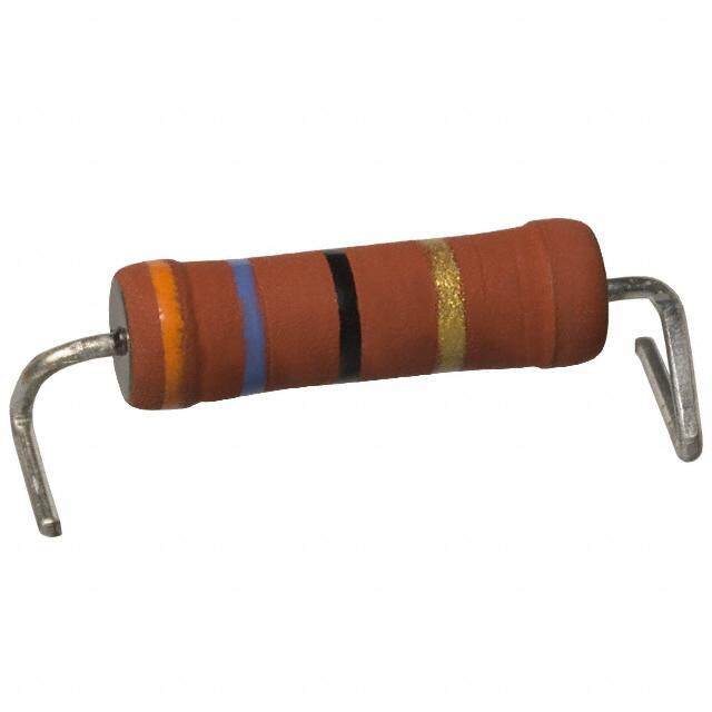
| 描述 | CAP TANT 68UF 100V 10% AXIAL钽质电容器-湿式 100volt 68uF 10% Extended Rating |
| ESR | 2.2 Ohms |
| ESR(等效串联电阻) | 2.2 欧姆 |
| 产品分类 | |
| 品牌 | Vishay |
| 产品手册 | |
| 产品图片 |
|
| rohs | 否含铅 / 不符合限制有害物质指令(RoHS)规范要求 |
| 产品系列 | 钽电容器,钽质电容器-湿式,Vishay 109D686X9100T2TANTALEX® 109D |
| 数据手册 | |
| 产品型号 | 109D686X9100T2 |
| 不同温度时的使用寿命 | - |
| 产品 | Tantalum Wet Sintered Anode |
| 产品培训模块 | http://www.digikey.cn/PTM/IndividualPTM.page?site=cn&lang=zhs&ptm=11952 |
| 产品种类 | 钽质电容器-湿式 |
| 制造商尺寸代码 | T |
| 制造商库存号 | T Case |
| 包装 | 托盘 |
| 商标 | Vishay |
| 商标名 | Tantalex |
| 外壳直径 | 10.31 mm |
| 外壳长度 | 23.4 mm |
| 大小/尺寸 | 0.406" 直径 x 0.921" 长(10.31mm x 23.40mm) |
| 安装类型 | 通孔 |
| 容差 | 10 % |
| 封装/外壳 | 轴向 |
| 工作温度 | -55°C ~ 125°C |
| 工作温度范围 | - 55 C to + 125 C |
| 引线间距 | - |
| 标准包装 | 1 |
| 漏泄电流 | 40 uA |
| 特性 | 液态钽 |
| 电压-额定 | 100V |
| 电压额定值 | 100 V |
| 电压额定值DC | 100 V |
| 电容 | 68 uF |
| 端接类型 | Axial |
| 类型 | Sintered Anode Tantalex Capacitors for Operation to + 125 C, Elastomer-Sealed |
| 系列 | 109D |
| 纹波电流 | 400 mA |
| 高度-安装(最大值) | - |


- 商务部:美国ITC正式对集成电路等产品启动337调查
- 曝三星4nm工艺存在良率问题 高通将骁龙8 Gen1或转产台积电
- 太阳诱电将投资9.5亿元在常州建新厂生产MLCC 预计2023年完工
- 英特尔发布欧洲新工厂建设计划 深化IDM 2.0 战略
- 台积电先进制程称霸业界 有大客户加持明年业绩稳了
- 达到5530亿美元!SIA预计今年全球半导体销售额将创下新高
- 英特尔拟将自动驾驶子公司Mobileye上市 估值或超500亿美元
- 三星加码芯片和SET,合并消费电子和移动部门,撤换高东真等 CEO
- 三星电子宣布重大人事变动 还合并消费电子和移动部门
- 海关总署:前11个月进口集成电路产品价值2.52万亿元 增长14.8%


PDF Datasheet 数据手册内容提取
109D www.vishay.com Vishay Wet Tantalum Capacitors Sintered Anode TANTALEX™ Capacitors for Operation to +125 °C, Elastomer-Sealed FEATURES • Axial through-hole terminations: standard tin / lead (SnPb), 100 % tin (RoHS-compliant) available Available • Vishay Sprague model 109D tubular elastomer-sealed, sintered anode TANTALEX Available capacitors fill the basic requirements for applications where a superior quality, reliabl e design for industrial, automotive and telecommunications application is desired Available • Model 109D capacitors are the commercial equivalents of Tansitor style WC, UWC, Mallory-NAC C style TLS, TLH and the military style CL64 and CL65, designed to meet the performance requirements o f military specification MIL-DTL-3965 • Material categorization: for definitions of complianc e please see www.vishay.com/doc?99912 Note * This datasheet provides information about parts that are RoHS-compliant and / or parts that are non RoHS-compliant. For example, parts with lead (Pb) terminations are not RoHS-compliant. Please see the information / tables in this datasheet for details PERFORMANCE CHARACTERISTICS Operating Temperature: -55 °C to +85 °C Following the life test: (to +125 °C with voltage derating) 1.DCL shall not exceed the initial requirements or 1 μA , Capacitance Tolerance: at 120 Hz, +25 °C. whichever is greater. ± 20 % standard. ± 10 %, ± 5 % available as special. 2.The ESR shall meet the initial requirement. DC Leakage Current (DCL max.): 3.Change in capacitance shall not exceed 10 % from the at +25 °C, +85 °C, +125 °C: leakage current shall not excee d initial measurement. For capacitors with voltage rating s the values listed in the Standard Ratings tables. of 15 V and below, change in capacitance shall not DC Life Test: capacitors are capable of withstanding a exceed + 10 %, - 25 % from the initial measurement. 2000 h life test at a temperature of +85 °C or +125 °C at the applicable DC working voltage. ORDERING INFORMATION 109D 207 X0 006 C 0 E3 MODEL CAPACITANCE CAPACITANCE DC VOLTAGE RATING CASE STYLE NUMBER RoHS-COMPLIANT TOLERANCE AT +85 °C CODE This is expressed X0 = ± 20 % This is expressed in volts. See 0 = no outer sleeve E3 = 100 % tin in picofarads. The X9 = ± 10 % To complete the Ratings Standard termination first two digits are X5 = ± 5 % three-digit block, zeros and Case 2 = outer plastic film (RoHS-compliant) the significant special order precede the voltage Codes insulation Blank = SnPb figures. The third is rating. A decimal point is table termination the number of indicated by an “R” (standard design) zeros to follow (6R3 = 6.3 V) Note • Packaging: the use of formed plastic trays for packaging these axial lead components is standard. Tape and reel is not available due to th e unit weight Revision: 05-Feb-2020 1 Document Number: 40023 For technical questions, contact: tantalum@vishay.com THIS DOCUMENT IS SUBJECT TO CHANGE WITHOUT NOTICE. THE PRODUCTS DESCRIBED HEREIN AND THIS DOCUMENT ARE SUBJECT TO SPECIFIC DISCLAIMERS, SET FORTH AT www.vishay.com/doc?91000
109D www.vishay.com Vishay DIMENSIONS in inches [millimeters] L 0.250 [6.35] max. - + 0.025 [0.635] dia. (no. 22 AWG) D tinned solderable leads WITH PLASTIC-FILM CASE BARE TUBE INSULATING SLEEVE LEAD LENGTH CODE D L D MAX. L (1) C 0.188 ± 0.016 [4.78 ± 0.41] 0.453 + 0.031 / - 0.016 [11.51 + 0.79 / - 0.41] 0.219 [5.56] 0.608 [15.45] 1.500 ± 0.250 [38.10 ± 6.35] F 0.281 ± 0.016 [7.14 ± 0.41] 0.641 + 0.031 / - 0.016 [16.28 + 0.79 / - 0.41] 0.312 [7.92] 0.796 [20.22] 2.250 ± 0.250 [57.15 ± 6.35] T 0.375 ± 0.016 [9.53 ± 0.41] 0.766 + 0.031 / - 0.016 [19.46 + 0.79 / - 0.41] 0.406 [10.31] 0.921 [23.40] 2.250 ± 0.250 [57.15 ± 6.35] K (2) 0.375 ± 0.016 [9.53 ± 0.41] 1.062 + 0.031 / - 0.016 [26.97 + 0.79 / - 0.41] 0.406 [10.31] 1.217 [30.91] 2.250 ± 0.250 [57.15 ± 6.35] Notes (1) For reference only (2) Replaces previous W case RATINGS AND CASE CODES (Standard) μF 6 V 8 V 10 V 15 V 20 V 25 V 30 V 35 V 50 V 60 V 75 V 100 V 125 V 1.7 C 2.5 C 3.0 C 3.5 C 3.6 C 4.0 C 4.5 C 4.7 C 5.0 C 6.8 C 7.0 C 8.0 C 8.2 C 9.0 F 10 C C F 11 F 13 F 14 F 15 C C F 18 T 20 C F 22 C C F F 25 C F T 27 C C 30 C T 33 C F 39 F 40 F T 43 T 47 C F 50 F T 56 C T K 60 T Revision: 05-Feb-2020 2 Document Number: 40023 For technical questions, contact: tantalum@vishay.com THIS DOCUMENT IS SUBJECT TO CHANGE WITHOUT NOTICE. THE PRODUCTS DESCRIBED HEREIN AND THIS DOCUMENT ARE SUBJECT TO SPECIFIC DISCLAIMERS, SET FORTH AT www.vishay.com/doc?91000
109D www.vishay.com Vishay RATINGS AND CASE CODES (Standard) μF 6 V 8 V 10 V 15 V 20 V 25 V 30 V 35 V 50 V 60 V 75 V 100 V 125 V 68 C F F T 70 F 82 T 86 K 100 F F / T T 110 K 120 F T 140 F K 150 T 160 K 170 T 180 F T 220 F T F 250 T 270 F T K 290 T T 300 K 330 T 350 K 390 T 430 T 540 K 560 T 750 K 850 K 1200 K RATINGS AND CASE CODES (Extended) μF 6 V 8 V 10 V 15 V 20 V 25 V 30 V 35 V 50 V 60 V 75 V 100 V 125 V 2.0 C 6.8 C 8.2 C 10 C 12 C 15 C 18 C 22 C C 27 C F 33 C C F 39 C F T 47 C C C F T 56 C C F T K 68 C C F T 82 C C F F K 86 T 100 C C F 110 T 120 C F F K 140 C T 150 C F 160 T Revision: 05-Feb-2020 3 Document Number: 40023 For technical questions, contact: tantalum@vishay.com THIS DOCUMENT IS SUBJECT TO CHANGE WITHOUT NOTICE. THE PRODUCTS DESCRIBED HEREIN AND THIS DOCUMENT ARE SUBJECT TO SPECIFIC DISCLAIMERS, SET FORTH AT www.vishay.com/doc?91000
109D www.vishay.com Vishay RATINGS AND CASE CODES (Extended) μF 6 V 8 V 10 V 15 V 20 V 25 V 30 V 35 V 50 V 60 V 75 V 100 V 125 V 180 C F F T 200 T 220 F F T T K 250 T 270 F F T K K 330 F F T K 350 T 390 F F T T 470 F F T K 510 T 540 T 560 F T K 680 F K 750 K 820 F T / K 1000 T K 1200 T / K 1500 T K 1800 K 2200 K STANDARD RATINGS MAX. DCL MAX. CAPACITANCE MAX. RMS MAX. ESR MAX. IMP. (μA) AT CHANGE (%) AT RIPPLE CAPACITANCE CASE AT +25 °C AT -55 °C PART NUMBER (1) CURRENT (μF) CODE 12(0 H) z 12(0 H) z +25 °C ++18255 ° °CC -55 °C +85 °C +125 °C 1(2m0 AH)z 6 V AT +85 °C; 7 V AT +125 °C DC DC 30 C 109D306X0006C0 4.2 100 1.0 2.0 -40 +10.5 +12 140 68 C 109D686X0006C0 4.0 60 1.0 2.0 -40 +14 +16 160 140 F 109D147X0006F0 2.0 40 1.0 3.0 -40 +14 +16 330 270 F 109D277X0006F0 4.0 25 1.0 7.0 -44 +17.5 +20 270 290 T 109D297X0006T0 2.0 24 2.0 7.0 -70 +20 +20 410 330 T 109D337X0006T0 2.1 20 2.0 7.9 -44 +14 +16 410 560 T 109D567X0006T0 3.0 25 2.0 13 -64 +17.5 +20 340 1200 K 109D128X0006K0 1.6 20 3.0 14 -80 +25 +25 530 8 V AT +85 °C; 5 V AT +125 °C DC DC 22 C 109D226X0008C0 6.0 115 1.0 2.0 -40 +10.5 +12 130 25 C 109D256X0008C0 4.2 100 1.0 2.0 -40 +10.5 +12 140 56 C 109D566X0008C0 4.0 59 1.0 2.0 -40 +14 +16 160 220 F 109D227X0008F0 4.0 30 1.0 7.0 -44 +17.5 +20 270 290 T 109D297X0008T0 2.0 24 2.0 9.5 -70 +20 +20 410 430 T 109D437X0008T0 3.2 25 2.0 14 -64 +17.5 +20 410 850 K 109D857X0008K0 1.0 22 4.0 16 -80 +25 +25 670 10 V AT +85 °C; 7 V AT +125 °C DC DC 20 C 109D206X0010C0 5.0 175 1.0 2.0 -32 +10.5 +12 140 47 C 109D476X0010C0 5.0 100 1.0 2.0 -36 +14 +16 160 100 F 109D107X0010F0 2.1 60 1.0 4.0 -36 +14 +16 270 180 F 109D187X0010F0 4.0 40 1.0 7.0 -36 +14 +16 270 250 T 109D257X0010T0 2.0 30 2.0 10 -40 +14 +16 410 390 T 109D397X0010T0 3.0 25 2.0 16 -64 +17.5 +20 340 750 K 109D757X0010K0 1.0 23 4.0 16 -80 +25 +25 670 Note (1) Part numbers shown are for units with ± 20 % capacitance tolerance and uninsulated capacitors. For ± 10 % units, change the digit following the letter “X” from “0” to “9”. For units with outer plastic-film insulation, substitute “2” for “0” at the end of the part number. For RoHS-compliant add “E3” Revision: 05-Feb-2020 4 Document Number: 40023 For technical questions, contact: tantalum@vishay.com THIS DOCUMENT IS SUBJECT TO CHANGE WITHOUT NOTICE. THE PRODUCTS DESCRIBED HEREIN AND THIS DOCUMENT ARE SUBJECT TO SPECIFIC DISCLAIMERS, SET FORTH AT www.vishay.com/doc?91000
109D www.vishay.com Vishay STANDARD RATINGS MAX. DCL MAX. CAPACITANCE MAX. RMS MAX. ESR MAX. IMP. (μA) AT CHANGE (%) AT RIPPLE CAPACITANCE CASE AT +25 °C AT -55 °C PART NUMBER (1) CURRENT (μF) CODE 12(0 H) z 12(0 H) z +25 °C ++18255 ° °CC -55 °C +85 °C +125 °C 1(2m0 AH)z 15 V AT +85 °C; 10 V AT +125 °C DC DC 15 C 109D156X0015C0 6.0 155 1.0 2.0 -24 +10.5 +12 130 33 C 109D336X0015C0 5.0 90 1.0 2.0 -28 +14 +16 160 70 F 109D706X0015F0 3.6 75 1.0 4.0 -28 +14 +16 270 120 F 109D127X0015F0 4.0 50 1.0 7.0 -28 +17.5 +20 270 270 T 109D277X0015T0 3.0 30 2.0 16 -56 +17.5 +20 340 540 K 109D547X0015K0 1.2 23 6.0 24 -80 +25 +25 610 20 V AT +85 °C; 13 V AT +125 °C DC DC 27 C 109D276X0020C0 5.0 100 1.0 2.0 -20 +11 +14 160 220 T 109D227X0020T0 4.0 3 2.0 16 -48 +13 +15 410 25 V AT +85 °C; 15 V AT +125 °C DC DC 10 C 109D106X0025C0 6.0 220 1.0 2.0 -16 +8 +9 130 22 C 109D226X0025C0 5.0 140 1.0 3.0 -20 +10.5 +12 160 50 F 109D506X0025F0 4.0 70 1.0 5.0 -28 +13 +15 270 100 F 109D107X0025F0 4.0 50 1.0 10 -28 +13 +15 270 100 T 109D107X0025T0 4.0 45 2.0 10 -48 +13 +15 410 180 T 109D187X0025T0 4.0 32 2.0 18 -48 +13 +15 340 220 F 109D227X0025F0 2.6 36 3.2 16 -60 +13 +16 300 350 K 109D357X0025K0 1.3 24 7.0 28 -70 +25 +25 580 30 V AT +85 °C; 20 V AT +125 °C DC DC 7.0 C 109D705X0030C0 8.0 275 1.0 2.0 -16 +8 +12 110 8.0 C 109D805X0030C0 7.5 275 1.0 2.0 -16 +8 +12 130 15 C 109D156X0030C0 8.0 175 1.0 2.0 -20 +10.5 +12 160 40 F 109D406X0030F0 4.0 65 1.0 5.0 -24 +10.5 +12 270 68 F 109D686X0030F0 6.0 60 1.0 8.0 -24 +13 +15 270 100 T 109D107X0030T0 6.0 40 2.0 12 -28 +10.5 +12 410 150 T 109D157X0030T0 4.1 35 2.0 18 -48 +13 +15 340 300 K 109D307X0030K0 1.6 25 8.0 32 -60 +25 +25 550 35 V AT +85 °C; 22 V AT +125 °C DC DC 68 F 109D686X0035F0 6.0 60 1.0 8 -24 +12 +15 270 120 T 109D127X0035T0 4.0 38 2.0 16 -30 +13 +15 410 270 K 109D277X0035K0 2.2 23 8.0 32 -45 +20 +25 500 50 V AT +85 °C; 30 V AT +125 °C DC DC 4.5 C 109D455X0050C0 9.0 400 1.0 2.0 -16 +5 +6 110 5.0 C 109D505X0050C0 9.0 400 1.0 2.0 -16 +5 +6 130 10 C 109D106X0050C0 8.0 250 1.0 2.0 -24 +8 +9 160 22 F 109D226X0050F0 7.0 95 1.0 4.0 -20 +10.5 +12 230 25 F 109D256X0050F0 6.0 95 1.0 5.0 -20 +10.5 +12 270 47 F 109D476X0050F0 6.0 70 1.0 9.0 -28 +13 +15 270 60 T 109D606X0050T0 3.0 45 2.0 12 -16 +10.5 +12 410 82 T 109D826X0050T0 4.0 45 2.0 16 -32 +13 +15 340 160 K 109D167X0050K0 2.2 27 8.0 32 -50 +25 +25 460 Note (1) Part numbers shown are for units with ± 20 % capacitance tolerance and uninsulated capacitors. For ± 10 % units, change the digit following the letter “X” from “0” to “9”. For units with outer plastic-film insulation, substitute “2” for “0” at the end of the part number. For RoHS-compliant add “E3” Revision: 05-Feb-2020 5 Document Number: 40023 For technical questions, contact: tantalum@vishay.com THIS DOCUMENT IS SUBJECT TO CHANGE WITHOUT NOTICE. THE PRODUCTS DESCRIBED HEREIN AND THIS DOCUMENT ARE SUBJECT TO SPECIFIC DISCLAIMERS, SET FORTH AT www.vishay.com/doc?91000
109D www.vishay.com Vishay STANDARD RATINGS MAX. DCL MAX. CAPACITANCE MAX. RMS MAX. ESR MAX. IMP. (μA) AT CHANGE (%) AT RIPPLE CAPACITANCE CASE AT +25 °C AT -55 °C PART NUMBER (1) CURRENT (μF) CODE 12(0 H) z 12(0 H) z +25 °C ++18255 ° °CC -55 °C +85 °C +125 °C 1(2m0 AH)z 60 V AT +85 °C; 40 V AT +125 °C DC DC 4.0 C 109D405X0060C0 10.0 550 1.0 2.0 -16 +5 +6 110 8.2 C 109D825X0060C0 8.0 275 1.0 2.0 -24 +8 +9 140 20 F 109D206X0060F0 5.0 105 1.0 5.0 -16 +10.5 +12 270 39 F 109D396X0060F0 7.0 90 1.0 9.0 -28 +10.5 +12 230 50 T 109D506X0060T0 4.0 50 2.0 12 -16 +10.5 +12 410 68 T 109D686X0060T0 6.0 50 2.0 16 -32 +10.5 +12 340 140 K 109D147X0060K0 2.4 28 8.0 32 -40 +20 +20 430 75 V AT +85 °C; 50 V AT +125 °C DC DC 3.5 C 109D355X0075C0 10.0 650 1.0 2.0 -16 +5 +6 110 6.8 C 109D685X0075C0 8.0 300 1.0 2.0 -20 +8 +9 140 13 F 109D136X0075F0 6.0 160 1.0 4.0 -16 +8 +9 190 15 F 109D156X0075F0 6.5 150 1.0 5.0 -16 +8 +9 270 33 F 109D336X0075F0 7.0 90 1.0 10 -24 +10.5 +15 230 40 T 109D406X0075T0 5.0 60 2.0 12 -16 +10.5 +12 410 56 T 109D566X0075T0 6.0 60 2.0 17 -28 +10.5 +15 300 110 K 109D117X0075K0 3.1 29 9.0 36 -35 +20 +20 400 100 V AT +85 °C; 65 V AT +125 °C DC DC 2.5 C 109D255X0100C0 26.5 950 1.0 2.0 -16 +7 +8 100 3.0 C 109D305X0100C0 10.0 800 1.0 2.0 -16 +7 +8 110 4.7 C 109D475X0100C0 10.0 500 1.0 2.0 -16 +7 +8 130 10 F 109D106X0100F0 6.0 215 1.0 4.0 -16 +7 +8 190 11 F 109D116X0100F0 6.0 200 1.0 4.0 -16 +7 +8 230 22 F 109D226X0100F0 7.0 100 1.0 9.0 -16 +7 +8 230 30 T 109D306X0100T0 4.0 80 2.0 12 -16 +7 +8 340 43 T 109D436X0100T0 6.0 70 2.0 17 -20 +7 +8 300 86 K 109D866X0100K0 3.1 30 9.0 36 -25 +15 +15 400 125 V AT +85 °C; 85 V AT +125 °C DC DC 1.7 C 109D175X0125C0 54.6 1250 1.0 2.0 -16 +7 +8 100 3.6 C 109D365X0125C0 15.0 600 1.0 2.0 -16 +7 +8 110 9.0 F 109D905X0125F0 15.0 240 1.0 5.0 -16 +7 +8 210 14 F 109D146X0125F0 12.0 167 1.0 7.0 -16 +7 +8 190 18 T 109D186X0125T0 11.0 129 2.0 9.0 -16 +7 +8 340 25 T 109D256X0125T0 10.0 93 2.0 13 -16 +7 +8 260 56 K 109D566X0125K0 4.1 3.2 10 40 -25 +15 +15 400 Note (1) Part numbers shown are for units with ± 20 % capacitance tolerance and uninsulated capacitors. For ± 10 % units, change the digit following the letter “X” from “0” to “9”. For units with outer plastic-film insulation, substitute “2” for “0” at the end of the part number. For RoHS-compliant add “E3” Revision: 05-Feb-2020 6 Document Number: 40023 For technical questions, contact: tantalum@vishay.com THIS DOCUMENT IS SUBJECT TO CHANGE WITHOUT NOTICE. THE PRODUCTS DESCRIBED HEREIN AND THIS DOCUMENT ARE SUBJECT TO SPECIFIC DISCLAIMERS, SET FORTH AT www.vishay.com/doc?91000
109D www.vishay.com Vishay EXTENDED RATINGS MAX. DCL MAX. CAPACITANCE MAX. RMS MAX. ESR MAX. IMP. (μA) AT CHANGE (%) AT RIPPLE CAPACITANCE CASE AT +25 °C AT -55 °C PART NUMBER (1) CURRENT (μF) CODE 12(0 H) z 12(0 H) z +25 °C ++18255 °°CC -55 °C +85 °C +125 °C 1(2m0 AH)z 6 V AT +85 °C; 7 V AT +125 °C DC DC 140 C 109D147X0006C2 3.0 54 2.0 9.0 -45 +13 +16 160 820 F 109D827X0006F0 2.5 18 3.0 14 -88 +16 +20 300 1500 T 109D158X0006T0 1.5 18 5.0 20 -90 +20 +25 480 2200 K 109D228X0006K0 1.0 13 6.0 24 -90 +25 +30 670 8 V AT +85 °C; 5 V AT +125 °C DC DC 180 C 109D187X0008C0 3.0 45 2.0 9.0 -60 +13 +16 180 470 F 109D477X0008F0 2.5 25 3.0 14 -75 +16 +20 300 680 F 109D687X0008F0 2.5 22 3.0 14 -90 +16 +20 300 1800 K 109D188X0008K0 1.0 14 7.0 25 -60 +20 +30 670 10 V AT +85 °C; 7 V AT +125 °C DC DC 100 C 109D107X0010C0 3.0 60 2.0 9.0 -50 +13 +16 160 120 C 109D127X0010C0 4.0 60 2.0 9.0 -45 +13 +16 160 150 C 109D157X0010C0 3.0 54 2.0 9.0 -55 +13 +16 180 390 F 109D397X0010F0 2.5 30 3.0 16 -70 +16 +20 300 470 F 109D477X0010F0 2.5 30 3.0 16 -65 +16 +20 300 560 F 109D567X0010F0 2.5 27 3.0 16 -77 +16 +20 300 1000 T 109D108X0010T0 1.5 20 5.0 20 -75 +20 +25 480 1200 K 109D128X0010K0 1.0 18 7.0 25 -75 +30 +30 670 1200 T 109D128X0010T0 1.5 18 5.0 20 -88 +20 +25 480 1500 K 109D158X0010K0 1.0 15 7.0 25 -88 +25 +30 670 15 V AT +85 °C; 10 V AT +125 °C DC DC 68 C 109D686X0015C0 4.0 80 2.0 9.0 -40 +13 +16 140 82 C 109D826X0015C0 4.0 80 2.0 9.0 -38 +13 +16 160 100 C 109D107X0015C0 4.0 72 2.0 9.0 -44 +13 +16 160 270 F 109D277X0015F0 2.5 35 3.0 16 -60 +16 +20 300 330 F 109D337X0015F0 2.5 35 3.0 16 -60 +16 +20 300 390 F 109D397X0015F0 2.5 31 3.0 16 -66 +16 +20 300 510 T 109D517X0015T0 1.8 25 6.0 24 -65 +20 +25 340 540 T 109D547X0015T0 1.8 22 6.0 24 -77 +20 +25 440 820 T 109D827X0015T0 1.8 22 6.0 24 -77 +20 +25 440 820 K 109D827X0015K0 1.2 20 8.0 32 -70 +30 +30 610 1000 K 109D108X0015K0 1.2 17 8.0 32 -77 +25 +30 610 20 V AT +85 °C; 13 V AT +125 °C DC DC 56 C 109D566X0020C0 4.3 90 2.0 9.0 -38 +13 +16 140 82 C 109D826X0020C0 4.3 81 2.0 9.0 -43 +13 +16 160 220 F 109D227X0020F0 2.7 35 3.0 16 -60 +16 +20 300 330 F 109D337X0020F0 2.7 31 3.0 16 -66 +16 +20 300 25 V AT +85 °C; 15 V AT +125 °C DC DC 47 C 109D476X0025C0 4.3 100 2.0 9.0 -35 +12 +15 140 68 C 109D686X0025C0 4.3 90 2.0 9.0 -40 +12 +15 160 180 F 109D187X0025F0 2.7 37 3.0 16 -55 +13 +16 300 270 F 109D277X0025F0 2.7 33 3.0 16 -62 +13 +16 300 350 T 109D357X0025T0 1.8 27 7.0 28 -60 +20 +25 440 560 T 109D567X0025T0 1.8 24 7.0 28 -72 +20 +25 440 680 K 109D687X0025K0 1.2 19 8.0 32 -72 +25 +30 610 750 K 109D757X0025K2 1.0 18 8.0 29 -60 +25 +25 610 Note (1) Part numbers shown are for units with ± 20 % capacitance tolerance and uninsulated capacitors. For ± 10 % units, change the digit following the letter “X” from “0” to “9”. For units with outer plastic-film insulation, substitute “2” for “0” at the end of the part number. For RoHS-compliant add “E3” Revision: 05-Feb-2020 7 Document Number: 40023 For technical questions, contact: tantalum@vishay.com THIS DOCUMENT IS SUBJECT TO CHANGE WITHOUT NOTICE. THE PRODUCTS DESCRIBED HEREIN AND THIS DOCUMENT ARE SUBJECT TO SPECIFIC DISCLAIMERS, SET FORTH AT www.vishay.com/doc?91000
109D www.vishay.com Vishay EXTENDED RATINGS MAX. DCL MAX. CAPACITANCE MAX. RMS MAX. ESR MAX. IMP. (μA) AT CHANGE (%) AT RIPPLE CAPACITANCE CASE AT +25 °C AT -55 °C PART NUMBER (1) CURRENT (μF) CODE 12(0 H) z 12(0 H) z +25 °C ++18255 °°CC -55 °C +85 °C +125 °C 1(2m0 AH)z 30 V AT +85 °C; 20 V AT +125 °C DC DC 39 C 109D396X0030C0 5.2 110 2.0 9.0 -28 +10 +12 140 47 C 109D476X0030C0 5.2 100 2.0 9.0 -30 +10 +12 140 56 C 109D566X0030C0 5.2 100 2.0 9.0 -38 +12 +15 140 150 F 109D157X0030F0 2.5 40 3.0 9.0 -40 +12 +15 300 180 F 109D187X0030F0 2.5 40 3.0 16 -45 +13 +16 300 220 F 109D227X0030F0 2.5 36 3.0 16 -60 +13 +16 300 330 T 109D337X0030T0 1.8 28 8.0 16 -45 +20 +25 440 390 T 109D397X0030T0 1.8 28 8.0 32 -50 +20 +25 440 470 T 109D477X0030T0 1.8 25 8.0 32 -65 +20 +25 550 560 K 109D567X0030K0 1.3 20 9.0 32 -65 +25 +30 590 35 V AT +85 °C; 22 V AT +125 °C DC DC 33 C 109D336X0035C0 5.2 130 2.0 9.0 -30 +10 +12 140 47 C 109D476X0035C0 5.2 115 2.0 9.0 -35 +10 +12 140 120 F 109D127X0035F0 2.5 45 3.0 16 -45 +13 +16 300 220 T 109D227X0035T0 1.8 30 8.0 32 -45 +20 +25 440 390 T 109D337X0035T0 1.8 27 8.0 32 -58 +20 +25 440 470 K 109D477X0035K0 1.3 21 9.0 36 -58 +25 +30 590 50 V AT +85 °C; 30 V AT +125 °C DC DC 22 C 109D226X0050C0 5.0 150 2.0 9.0 -24 +10 +12 140 33 C 109D336X0050C0 5.0 135 2.0 9.0 -29 +10 +12 140 82 F 109D826X0050F0 2.5 55 4.0 24 -35 +10 +15 300 120 F 109D127X0050F0 2.5 49 4.0 24 -42 +12 +15 300 160 T 109D167X0050T0 1.8 32 6.0 32 -35 +20 +25 420 250 T 109D257X0050T0 1.8 29 8.0 32 -40 +20 +25 440 270 T 109D277X0050T0 1.8 29 8.0 32 -46 +20 +25 440 330 K 109D337X0050K0 1.5 22 9.0 36 -46 +25 +30 550 60 V AT +85 °C; 40 V AT +125 °C DC DC 18 C 109D186X0060C0 5.0 160 3.0 12 -20 +10 +12 140 27 C 109D276X0060C0 5.0 144 3.0 12 -24 +10 +12 140 68 F 109D686X0060F0 3.0 60 3.0 20 -30 +12 +15 270 100 F 109D107X0060F0 2.5 54 4.0 20 -36 +12 +15 300 140 T 109D147X0060T0 2.0 32 8.0 32 -30 +16 +20 420 220 T 109D227X0060T0 1.8 29 8.0 32 -40 +16 +20 440 270 K 109D277X0060K0 1.5 23 9.0 36 -45 +20 +25 550 75 V AT +85 °C; 50 V AT +125 °C DC DC 12 C 109D126X0075C0 5.0 175 2.0 12 -12 +8 +10 140 15 C 109D156X0075C0 5.0 160 2.0 12 -14 +10 +12 140 22 C 109D226X0075C0 5.0 157 3.0 12 -19 +10 +12 140 47 F 109D476X0075F0 3.0 75 4.0 24 -18 +10 +12 270 56 F 109D566X0075F0 3.0 70 4.0 24 -20 +12 +15 270 82 F 109D826X0075F0 2.5 63 4.0 24 -30 +12 +15 300 110 T 109D117X0075T0 2.0 33 9.0 36 -25 +16 +20 420 180 T 109D187X0075T0 1.8 30 9.0 36 -35 +16 +20 440 200 T 109D207X0075T0 1.8 29 8.0 32 -40 +20 +25 440 220 K 109D227X0075K0 2.2 24 10 40 -40 +20 +25 450 270 K 109D277X0075K2 1.3 24 10 40 -40 +20 +25 450 Note (1) Part numbers shown are for units with ± 20 % capacitance tolerance and uninsulated capacitors. For ± 10 % units, change the digit following the letter “X” from “0” to “9”. For units with outer plastic-film insulation, substitute “2” for “0” at the end of the part number. For RoHS-compliant add “E3” Revision: 05-Feb-2020 8 Document Number: 40023 For technical questions, contact: tantalum@vishay.com THIS DOCUMENT IS SUBJECT TO CHANGE WITHOUT NOTICE. THE PRODUCTS DESCRIBED HEREIN AND THIS DOCUMENT ARE SUBJECT TO SPECIFIC DISCLAIMERS, SET FORTH AT www.vishay.com/doc?91000
109D www.vishay.com Vishay EXTENDED RATINGS MAX. DCL MAX. CAPACITANCE MAX. RMS MAX. ESR MAX. IMP. (μA) AT CHANGE (%) AT RIPPLE CAPACITANCE CASE AT +25 °C AT -55 °C PART NUMBER (1) CURRENT (μF) CODE 12(0 H) z 12(0 H) z +25 °C ++18255 °°CC -55 °C +85 °C +125 °C 1(2m0 AH)z 100 V AT +85 °C; 65 V AT +125 °C DC DC 2.0 C 109D205X0100C0 14.0 870 3.0 12 -20 +12 +12 100 8.2 C 109D825X0100C0 6.0 250 3.0 12 -12 +12 +12 130 10 C 109D106X0100C0 6.0 200 3.0 12 -17 +10 +12 130 33 F 109D336X0100F0 3.5 85 4.0 24 -18 +15 +15 250 39 F 109D396X0100F0 3.5 80 5.0 24 -20 +12 +15 250 56 T 109D566X0100T0 2.2 45 9.0 36 -20 +15 +15 400 68 T 109D686X0100T0 2.2 40 10 40 -30 +14 +16 400 86 T 109D866X0100T0 3.2 30 10 40 -25 +15 +15 370 120 K 109D127X0100K0 2.8 30 12 48 -35 +15 +17 440 125 V AT +85 °C; 85 V AT +125 °C DC DC 6.8 C 109D685X0125C0 11.7 300 3.0 12 -14 +10 +12 130 27 F 109D276X0125F0 3.5 90 5.0 24 -18 +12 +15 250 39 T 109D396X0125T0 2.2 60 10 40 -16 +14 +16 400 47 T 109D476X0125T0 2.2 50 10 40 -26 +14 +16 400 56 K 109D566X0125K0 4.1 32 10 40 -25 +15 +15 330 82 K 109D826X0125K0 2.8 32 12 48 -30 +15 +17 440 Note (1) Part numbers shown are for units with ± 20 % capacitance tolerance and uninsulated capacitors. For ± 10 % units, change the digit following the letter “X” from “0” to “9”. For units with outer plastic-film insulation, substitute “2” for “0” at the end of the part number. For RoHS-compliant add “E3” Revision: 05-Feb-2020 9 Document Number: 40023 For technical questions, contact: tantalum@vishay.com THIS DOCUMENT IS SUBJECT TO CHANGE WITHOUT NOTICE. THE PRODUCTS DESCRIBED HEREIN AND THIS DOCUMENT ARE SUBJECT TO SPECIFIC DISCLAIMERS, SET FORTH AT www.vishay.com/doc?91000
Legal Disclaimer Notice www.vishay.com Vishay Disclaimer ALL PRODUCT, PRODUCT SPECIFICATIONS AND DATA ARE SUBJECT TO CHANGE WITHOUT NOTICE TO IMPROV E RELIABILITY, FUNCTION OR DESIGN OR OTHERWISE. Vishay Intertechnology, Inc., its affiliates, agents, and employees, and all persons acting on its or their behalf (collectively, “Vishay”), disclaim any and all liability for any errors, inaccuracies or incompleteness contained in any datasheet or in any other disclosure relating to any product. Vishay makes no warranty, representation or guarantee regarding the suitability of the products for any particular purpose o r the continuing production of any product. To the maximum extent permitted by applicable law, Vishay disclaims (i) any and all liability arising out of the application or use of any product, (ii) any and all liability, including without limitation special, consequential or incidental damages, and (iii) any and all implied warranties, including warranties of fitness for particular purpose, non-infringement and merchantability. Statements regarding the suitability of products for certain types of applications are based on Vishay’s knowledge of typical requirements that are often placed on Vishay products in generic applications. Such statements are not binding statements about the suitability of products for a particular application. It is the customer’s responsibility to validate that a particular product with the properties described in the product specification is suitable for use in a particular application. Parameters provided in datasheets and / or specifications may vary in different applications and performance may vary over time. All operating parameters, including typical parameters, must be validated for each customer application by the customer’s technical experts. Product specifications do not expand or otherwise modify Vishay’s terms and conditions of purchase, including but not limited to the warranty expressed therein. Except as expressly indicated in writing, Vishay products are not designed for use in medical, life-saving, or life-sustainin g applications or for any other application in which the failure of the Vishay product could result in personal injury or death. Customers using or selling Vishay products not expressly indicated for use in such applications do so at their own risk . Please contact authorized Vishay personnel to obtain written terms and conditions regarding products designed for such applications. No license, express or implied, by estoppel or otherwise, to any intellectual property rights is granted by this documen t or by any conduct of Vishay. Product names and markings noted herein may be trademarks of their respective owners. © 2019 VISHAY INTERTECHNOLOGY, INC. ALL RIGHTS RESERVED Revision: 01-Jan-2019 1 Document Number: 91000