ICGOO在线商城 > 连接器,互连器件 > D-Sub,D 形连接器 - 后壳,罩 > 1-5206478-2

 Datasheet下载
- 型号: 1-5206478-2
- 制造商: CORCOM/TYCO ELECTRONICS
- 库位|库存: xxxx|xxxx
- 要求:
| 数量阶梯 | 香港交货 | 国内含税 |
| +xxxx | $xxxx | ¥xxxx |
查看当月历史价格
查看今年历史价格
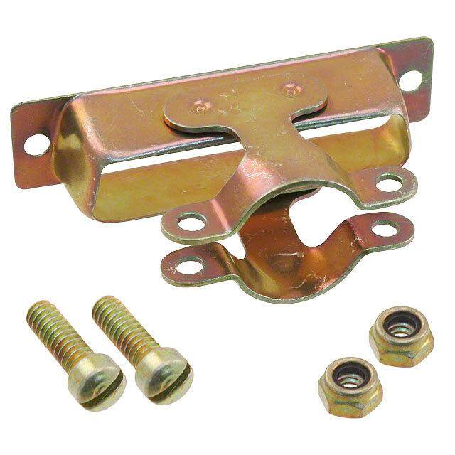
1-5206478-2产品简介:
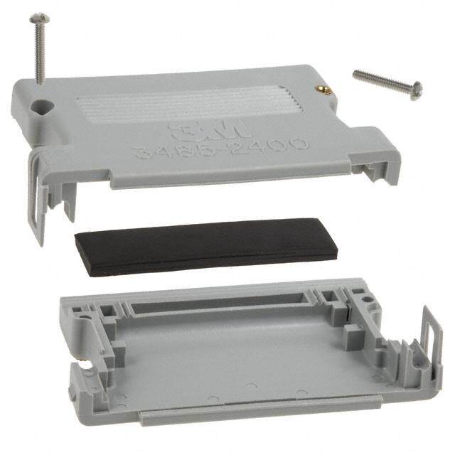
ICGOO电子元器件商城为您提供1-5206478-2由CORCOM/TYCO ELECTRONICS设计生产,在icgoo商城现货销售,并且可以通过原厂、代理商等渠道进行代购。 1-5206478-2价格参考¥34.63-¥34.63。CORCOM/TYCO ELECTRONICS1-5206478-2封装/规格:D-Sub,D 形连接器 - 后壳,罩, 25 Position Hinged Backshell Connector Black 45°, 180° Unshielded。您可以下载1-5206478-2参考资料、Datasheet数据手册功能说明书,资料中有1-5206478-2 详细功能的应用电路图电压和使用方法及教程。
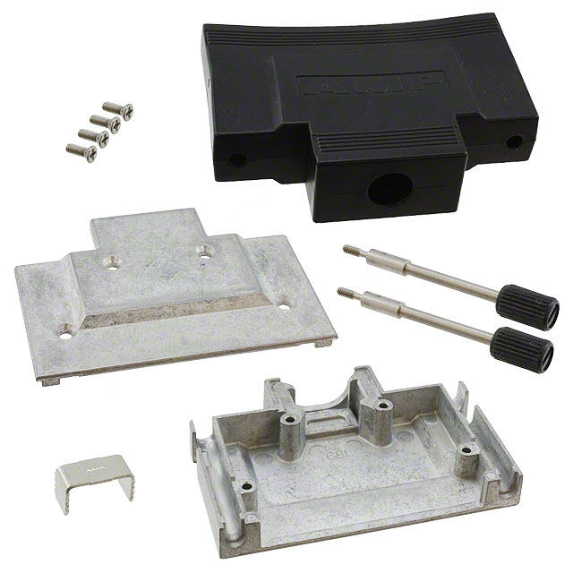
型号为1-5206478-2的TE Connectivity AMP Connectors品牌D-Sub连接器后壳,主要应用于需要可靠信号传输和机械保护的电子设备连接场景。该产品属于D形连接器附件,用于保护D-Sub连接器的插针和连接部位,防止灰尘、湿气和物理损坏。

其典型应用场景包括:

1. 工业控制设备:如PLC、工控机、传感器等,用于保障连接器在复杂环境中的稳定性和耐用性。
2. 通信设备:如交换机、路由器和通信基站,用于提升连接可靠性,防止信号干扰。
3. 测试与测量仪器:如示波器、万用表等,用于保护连接端口,延长设备使用寿命。
4. 医疗设备:用于对连接器要求高稳定性和清洁性的医疗仪器中,确保设备安全运行。
5. 交通运输系统:如轨道交通控制箱、车载电子设备,适应震动和温度变化较大的环境。

该后壳结构坚固,安装方便,适用于多种标准D-Sub连接器,提供良好的电磁屏蔽和机械防护,适用于工业、商业及部分军工环境。
| 参数 | 数值 |
| 3D型号 | http://www.te.com/commerce/DocumentDelivery/DDEController?Action=srchrtrv&DocNm=1-5206478-2&DocType=Customer+View+Model&DocLang=English |
| 产品目录 | |
| 描述 | CONN BACKSHELL DB25 PLASTICD-Sub工具与硬件 CBL CLAMP ASSY KIT |
| 产品分类 | |
| 品牌 | TE Connectivity / AMP |
| 产品手册 | http://www.te.com/catalog/pn/en/1-5206478-2?RQPN=1-5206478-2 |
| 产品图片 |
|
| rohs | 符合RoHS无铅 / 符合限制有害物质指令(RoHS)规范要求 |
| 产品系列 | D-Sub工具与硬件,TE Connectivity / AMP 1-5206478-2AMPLIMITE HD-20, AMP |
| 数据手册 | http://www.te.com/commerce/DocumentDelivery/DDEController?Action=srchrtrv&DocNm=5206478&DocType=Customer+Drawing&DocLang=English |
| 产品型号 | 1-5206478-2 |
| RoHS指令信息 | http://www.te.com/commerce/alt/SinglePartSearch.do?PN=1-5206478-2&dest=stmt点击此处下载产品Datasheet |
| 产品目录绘图 |
|
| 产品目录页面 | |
| 产品种类 | D-Sub工具与硬件 |
| 其它名称 | 152064782 |
| 商标 | TE Connectivity / AMP |
| 封装 | Bulk |
| 屏蔽 | 无屏蔽 |
| 工厂包装数量 | 20 |
| 材料 | 热塑塑胶 |
| 标准包装 | 1 |
| 特性 | 组件套件,配接螺钉 4-40 |
| 电缆出口 | 45°, 180° |
| 电缆类型 | 圆形 |
| 硬件 | 组装硬件,应力消除 |
| 配件类型 | 铰链后壳 |
| 针脚数 | 25 |
| 镀层 | - |
| 颜色 | 黑 |


.jpg)

- 商务部:美国ITC正式对集成电路等产品启动337调查
- 曝三星4nm工艺存在良率问题 高通将骁龙8 Gen1或转产台积电
- 太阳诱电将投资9.5亿元在常州建新厂生产MLCC 预计2023年完工
- 英特尔发布欧洲新工厂建设计划 深化IDM 2.0 战略
- 台积电先进制程称霸业界 有大客户加持明年业绩稳了
- 达到5530亿美元!SIA预计今年全球半导体销售额将创下新高
- 英特尔拟将自动驾驶子公司Mobileye上市 估值或超500亿美元
- 三星加码芯片和SET,合并消费电子和移动部门,撤换高东真等 CEO
- 三星电子宣布重大人事变动 还合并消费电子和移动部门
- 海关总署:前11个月进口集成电路产品价值2.52万亿元 增长14.8%

PDF Datasheet 数据手册内容提取
AMPLIMITESubminiatureDConnectors HDP-20CrimpSnap-InContactConnectors s r o ct e n n o C e bl a C Product Selection Guide Connector Contacts Insert ShellType Type Material MaterialandFinish Mounting Type Termination Plating Duplex ZincPlatedSteel (.000030 WithoutGrounding [0.00076] Indents Goldand .120 (cid:2)(cid:2) Tin) Plug 94V-0Rated TinPlatedSteel [3.05]Dia.Holes Pins Crimp (pg.92) Thermoplastic WithoutGrounding (pgs.100,101) Duplex Black Indents ClinchNut, Posted (GoldFlash 4-40Threads andTin) TinPlatedSteel WithGroundingIndents Select (.000030 [0.00076] (cid:2)(cid:2) Goldand GoldFlash) Duplex (.000030 [0.00076] Goldand Tin) .120 (cid:2)(cid:2) Receptacle 94V-0Rated ZincPlatedSteel [3.05]Dia.Holes Sockets Crimp Duplex (pg.93) Thermoplastic (pgs.100,101) (GoldFlash Black TinPlatedSteel ClinchNuts, Posted andTin) 4-40Threaded Select (.000030 [0.00076] Goldand GoldFlash) 90 Catalog82068 Dimensionsareshownfor Dimensionsareininchesand Canada:+1(905)475-6222 UK:+44(0)800-267666 Revised4-12 referencepurposesonly. millimetersunlessotherwise Mexico/C.Am.:+52(0)55-1106-0800 France:+33(0)1-3420-8686 Specificationssubject specified. Latin/S.Am.:+54(0)11-4733-2200 Netherlands:+31(0)73-6246-999 www.te.com tochange. USA:+1(800)522-6752 Germany:+49(0)6251-133-1999 China:+86(0)400-820-6015
AMPLIMITE Subminiature D Connectors HDP-20 Crimp Snap-In Contact Connectors (Continued) Product Facts (cid:1) Machine applied Section Contents terminations assure highest (cid:1) Shell sizes offer wide Plug and Receptacle Connectors.....................92, 93 production rates choice of contact Basic Shielding Hardware Kits........................94, 95 at lowest applied cost positions—9, 15, 25, 37 Shielding Hardware Enclosure Kits ...................96, 97 and 50 (cid:1) Intermateable with any size Preassembled Shielded Connector Kits ..................98 20 Subminiature D con- Ferrules for Shielding Hardware Kits......................99 (cid:1) Lower cost, commercial nector dimensionally com- Contacts ...........................................100, 101 version of the military plying with MIL-C-24308 Application Tooling......................................102 approved series (cid:1) Tin or zinc plated shells, (cid:1) Recognized under the Component Program of with or without grounding Underwriters indents Laboratories Inc., (cid:1) Crimp snap-in contacts File No. E28476 R allows loading of only the number of contacts being (cid:1) Listed under Underwriters C Laboratories Inc., Standard a used b 1863, Communication le (cid:1) Available with shielding Circuit Accessories, C o hardware and shielding File No. E81956 n enclosure kits R ne (cid:1) Numerous cable clamps and (cid:1) CSetarntidfiaerdd sby Canadian ctor s mating hardware options Association, R (cid:1) Low cost, high File No. LR 1088108 performance, precision- (LR 7189-207) formed crimp contacts Contact Retention Features Pin Radius lead-in minimizes force Shielded Cable needed to insert contact into housing Unshielded Clamps and Mounting and Cable Clamps Shielding Hardware Mating Hardware and Enclosure Kits Keying Plug One-Piece (pg. 155) Generous lead-in to Cable Clamp minimize “stubbing“ 180°/120° Male Screw Quik-Snap Straight Exit Retainers Socket (pg. 134) RFI/EMI Shields (pgs. 146, 147) for Jacketed Box and Lid Cable (pgs. 139, Female Radius lead-in minimizes force S(ptgra. i1g3h7t/)90° Exit 142) S(pcgr.e 1w4lo8c)ks ninetoe dheodu stoin ignsert contact (cid:2)(cid:2) 90° Exit Die Cast (cid:2)(cid:2) Box and Lid with RFI/EMI Shields Locking Posts Male Screw for Jacketed Cable and Slide Retainers (pg. 142) Latches (pg. 137) (pgs. 149, 151) Basic Shielding Clam Shell Hardware Kits Spring Latch, Straight/45° Exit (pgs. 94, 95) Two-Piece (pg. 138) (pg. 152) Shielding Clam Shell Hardware Latching Blocks Housing Cutaway Contact bearing surface Straight/45° Exit Enclosure Kits (pgs. 153, 154) is large and symmetrical with Male Screw (pgs. 96, 97) Standoff Retainers Bushings (pg. 138) (pg. 155) Reinforced Ribs 91 Catalog 82068 Dimensions are shown for Dimensions are in inches and Canada: +1 (905) 475-6222 UK: +44 (0) 800-267666 Revised 4-12 reference purposes only. millimeters unless otherwise Mexico/C. Am.: +52 (0) 55-1106-0800 France: +33 (0) 1-3420-8686 Specifications subject specified. Latin/S. Am.: +54 (0) 11-4733-2200 Netherlands: +31 (0) 73-6246-999 www.te.com to change. USA: +1 (800) 522-6752 Germany: +49 (0) 6251-133-1999 China: +86 (0) 400-820-6015
AMPLIMITE Subminiature D Connectors HDP-20 Crimp Snap-In Contact Connectors (Continued) Plug A B .120 [3.05]Dia. C Typ. 2 Holes Material and Finish: Shell—Steel, zinc or tin plated Grounding Indents Insert—94V-0 rated thermoplastic, black (See Table) Mating Face .230 [5.84] s or Mounting Holes: ect Standard—.120 [3.05] Dia. [1.402.607]Ref. n Con Csellifn-lcohc kNinugt —fea4tu-4re0 threads with [1.403.927]Max. e bl a C Related Product Data: Contact Arrangements—page 40 Performance Characteristics— page 41 Contacts—pages 100, 101 Application Tooling—page 102 Mateable Connectors: HDE—pages 110-123 HDP—pages 90-102 HD-20 Board Mount— pages 54-71, 78-85, 87-89 Mating/Panel Mounting—page 42 Cable Clamps—pages 132, 133, 135-137, 140, 141, 144, 145 Mating Hardware—pages 146-150, 153, 155 Technical Documents: Product Specification—108-40005 Application Specifications— 114-10000, 114-40030 .[120.504] Max. Clinch Nut (Plug and Receptacle) Note:Instruction Sheets for TE Tooling are packaged with the tooling. For additional information call the Tooling Assistance Center: 1-800-722-1111. 92 Catalog 82068 Dimensions are shown for Dimensions are in inches and Canada: +1 (905) 475-6222 UK: +44 (0) 800-267666 Revised 4-12 reference purposes only. millimeters unless otherwise Mexico/C. Am.: +52 (0) 55-1106-0800 France: +33 (0) 1-3420-8686 Specifications subject specified. Latin/S. Am.: +54 (0) 11-4733-2200 Netherlands: +31 (0) 73-6246-999 www.te.com to change. USA: +1 (800) 522-6752 Germany: +49 (0) 6251-133-1999 China: +86 (0) 400-820-6015
AMPLIMITE Subminiature D Connectors HDP-20 Crimp Snap-In Contact Connectors (Continued) Receptacle A B .120 [3.05]Dia. C Typ. 2 Holes .243 Mating Face [6.17] C a [1.403.902]Ref. ble .432 C [7.90] Max. on n e c to r s Plug Part Numbers Receptacle Part Nos. SShizeell PCoNosonit.ti aoocnfts A DimenBsions C MInatseerrital MMoeutnhtoindg PSZlahinteecldl GWroiuthnTodiunint PglatedG SrohWueniltldhing PSZlahinteecldl PSlTahiteneldl Indents Indents 1.213 .984 .494 Standard 205204-9 205204-8 205204-4 205203-8 205203-3 1 9 94V-0 30.81 24.99 12.55 Clinch Nut — 1658642-2 1658642-1 — 1658643-1 1.541 1.312 .494 Standard 205206-9 205206-8 205206-3 205205-7 205205-2 2 15 94V-0 39.14 33.33 12.55 * Clinch Nut — — 5745908-2 — 1658644-1 2.088 1.852 .494 Standard 5205208-1 207464-7 207464-2 5205207-1 207463-1 3 25 94V-0 53.04 47.04 12.55 Clinch Nut — — 5745036-2 207516-6 207516-5 2.729 2.500 .494 Standard 205210-8 205210-7 205210-3 205209-7 205209-2 4 37 94V-0 69.32 63.50 12.55 Clinch Nut — — 745135-4 — 5207661-3 2.635 2.406 .605 Standard 1658641-3 1658641-1 1658641-2 1658640-2 1658640-1 5 50 94V-0 66.93 61.11 15.37 Clinch Nut — — 5745883-2 — 5745884-1 Note: Plugs accept size 20 DF pin contacts and receptacles accept size 20 DF socket contacts. .[120.504] Max. Clinch Nut (Plug and Receptacle) Note:Instruction Sheets for TE Tooling are packaged with the tooling. For additional information call the Tooling Assistance Center: 1-800-722-1111. Note:All part numbers are RoHS compliant. 93 Catalog 82068 Dimensions are shown for Dimensions are in inches and Canada: +1 (905) 475-6222 UK: +44 (0) 800-267666 Revised 4-12 reference purposes only. millimeters unless otherwise Mexico/C. Am.: +52 (0) 55-1106-0800 France: +33 (0) 1-3420-8686 Specifications subject specified. Latin/S. Am.: +54 (0) 11-4733-2200 Netherlands: +31 (0) 73-6246-999 www.te.com to change. USA: +1 (800) 522-6752 Germany: +49 (0) 6251-133-1999 China: +86 (0) 400-820-6015
AMPLIMITE Subminiature D Connectors HDP-20 Basic Shielding Hardware Kits Plug .120 Typ. [.21.0797]Typ. [3.05]2 Holes .509 [12.93]Max. .112 [2.84] Typ. [.52.3804] GIrnoduenndtisng .195 Max. Plug Connector [4.95] Typ. s r o ect Each kit contains: n on (cid:1)Connector C E e (cid:1)Inner shield bl (cid:1)Outer shield Ca Contacts and ferrules must be purchased SInhsiiedled Outside separately. Shield Material and Finish: Connector Shells—Steel, tin plated D Connector Insert—94V-0 rated ther- moplastic, black Shield—Steel, tin plated Ferrule (Must Be Purchased Separately) View of Rear Shell Related Product Data: (With Shields Removed) Contact Arrangements—page 40 [1.416.723]Max. Performance Characteristics— page 41 Contacts—pages 100, 101 Application Tooling—page 102 Mateable Connectors: HDE—pages 110-123 HDP—pages 90-102 HD-20 Board Mount— pages 54-71, 78-85, 87-89 Mating/Panel Mounting—page 42 Mating Hardware—pages 146-150, 153, 155 Ferrules—page 99 Technical Documents: Product Specifications— 108-40005 108-40030 Application Specifications— 114-10000 114-40030 Instruction Sheet—408-9010 Note:Instruction Sheets for TE Tooling are packaged with the tooling. For additional information call the Tooling Assistance Center: 1-800-722-1111. 94 Catalog 82068 Dimensions are shown for Dimensions are in inches and Canada: +1 (905) 475-6222 UK: +44 (0) 800-267666 Revised 4-12 reference purposes only. millimeters unless otherwise Mexico/C. Am.: +52 (0) 55-1106-0800 France: +33 (0) 1-3420-8686 Specifications subject specified. Latin/S. Am.: +54 (0) 11-4733-2200 Netherlands: +31 (0) 73-6246-999 www.te.com to change. USA: +1 (800) 522-6752 Germany: +49 (0) 6251-133-1999 China: +86 (0) 400-820-6015
AMPLIMITE Subminiature D Connectors HDP-20 Basic Shielding Hardware Kits (Continued) Receptacle .120 Typ. [.21.0797]Typ. [3.05]2 Holes .509 [12.93]Max. .112 [2.84] Typ. Rcpt. Connector .243 [6.17] .195 Max. [4.95] Typ. C a b le C o n n E ec to Inside r Shield Outside s Shield D .[120.504] Max. Ferrule (Must Be Purchased Separately) View of Rear Shell (With Shields Removed) .462 [11.73]Max. Clinch Nut (Plug and Receptacle) Recommended Max. Inner Shell No. of Dimensions Cable Cable Mounting Contact Plug Kit Numbers Receptacle Kit Numbers Size Positions D E Outer Dia. Bundle Method Range Dia.† .700 1.535 .165-.455 .350 Standard 1658645-1 1658646-1 1 9 17.78 38.99 4.19-11.56 8.89 Clinch Nut 5748526-1 5748536-1 1.024 1.535 .165-.455 .350 Standard 1658647-1 5747539-1 2 15 26.01 38.99 4.19-11.56 8.89 Clinch Nut 5750636-1 5787908-1 1.576 1.535 .165-.455 .350 Standard 1658648-1 1658649-1 3 25 40.03 38.99 4.16-11.56 8.89 Clinch Nut — 1658662-1 2.215 1.892 .338-.562 .450 Standard 1658650-1 1658651-1 4 37 56.26 48.06 8.59-14.28 11.43 Clinch Nut 5786929-1 — 2.120 1.876 .338-.480 .450 5 50 Standard 1658652-1 1658653-1 53.85 47.65 8.59-12.19 11.43 Notes: 1. Plugs accept size 20 DF pin contacts and receptacles accept size 20 DF socket contacts. 2. Components of the kits are shipped unassembled and bulk-packaged in quantities of 100 pieces. †Maximum cable diameter after jacket and braid removed. Note:All part numbers are RoHS compliant. 95 Catalog 82068 Dimensions are shown for Dimensions are in inches and Canada: +1 (905) 475-6222 UK: +44 (0) 800-267666 Revised 4-12 reference purposes only. millimeters unless otherwise Mexico/C. Am.: +52 (0) 55-1106-0800 France: +33 (0) 1-3420-8686 Specifications subject specified. Latin/S. Am.: +54 (0) 11-4733-2200 Netherlands: +31 (0) 73-6246-999 www.te.com to change. USA: +1 (800) 522-6752 Germany: +49 (0) 6251-133-1999 China: +86 (0) 400-820-6015
AMPLIMITE Subminiature D Connectors HDP-20 Shielding Hardware Enclosure Kits Plug Expanding Neck Accommodates Cable Ferrule (Must SBeep Paurarctehlay,s Aeds [.31.2158] FMax Required By Max. Cable Cable Diameter Ref. Each Kit Contains: (cid:1)Connector Jackscrew ors (cid:1)Inner shield Qty. 2 ect (cid:1)Outer shield n n (cid:1)Enclosure o C (cid:1)Two jackscrews DMax. able Cseopnatraacttesl ya.nd ferrules must be purchased SQhtyie. l2d .812 [13T.74y.p62.76] C [20.62] Typ. Material and Finish: Enclosure Connector Shells—Steel, tin plated. Connector Insert—94V-0 rated thermoplastic, black EMax. Shield—Steel, tin plated Plug Connector Enclosure—PVC, black HDP-20 Jackscrews—Zinc alloy Related Product Data: Contact Arrangements—page 40 Performance Characteristics— page 41 Contacts—pages 100, 101 Application Tooling—page 102 Mateable Connectors: HDE—pages 110-123 HDP—pages 90-102 HD-20 Board Mount— pages 54-71, 78-85, 87-89 Mating/Panel Mounting—page 42 Mating Hardware—pages 146-150, 153, 155 Ferrules—page 99 Technical Documents: Product Specifications— 108-40005 108-40030 Application Specifications— 114-10000 114-40030 Instruction Sheet—408-9172 Note:Instruction Sheets for TE Tooling are packaged with the tooling. For additional information call the Tooling Assistance Center: 1-800-722-1111. 96 Catalog 82068 Dimensions are shown for Dimensions are in inches and Canada: +1 (905) 475-6222 UK: +44 (0) 800-267666 Revised 4-12 reference purposes only. millimeters unless otherwise Mexico/C. Am.: +52 (0) 55-1106-0800 France: +33 (0) 1-3420-8686 Specifications subject specified. Latin/S. Am.: +54 (0) 11-4733-2200 Netherlands: +31 (0) 73-6246-999 www.te.com to change. USA: +1 (800) 522-6752 Germany: +49 (0) 6251-133-1999 China: +86 (0) 400-820-6015
AMPLIMITE Subminiature D Connectors HDP-20 Shielding Hardware Enclosure Kits (Continued) Receptacle Expanding Neck Ferrule (Must Be Purchased .125 FMax Cable Separately, As [3.18] Ref. Required By Typ. Cable Diameter Jackscrew C Qty. 2 a b le C o DMax. n n Shield e Qty. 2 1.467 c .812 [37.26] to [20.62] Typ. rs Typ. Enclosure EMax. Rcpt. Connector HDP-20 Shielding Recommended Max. Enclosure Shell No. of Dimensions Cable Inner Insert Kit Numbers Expansion Size PCoosnittiaocnts D E F DiOamuteetrer BCuanbdlele Material Plug Receptacle Tool Range Dia.† Cable Part O.D. (Max.) Number 1 9 412.6.1660 13.43.5452 1.66.3000 4.1.8930--8.3.3380 8.3.3380 94V-0 1658655-1 1658654-1 .330 2 15 412.6.1660 14.26.8850 1.66.3000 4.1.8930--8.3.3380 8.3.3380 94V-0 1658657-1 1658656-1 8.38 58241-4 3 25 412.6.1660 25.62.1103 1.66.3000 5..25117-1-.14.3055 8.3.8590 94V-0 1658659-1 1658658-1 1.415.403 58241-1 4 37 521.0.0150 27.28.6757 1.87.3504 8..35398-1-.45.6228 1.415.403 94V-0 5747958-1 1658660-1 .572 58241-2 5 50 521.0.0150 27.07.7459 1.87.3504 8..35398-1-.45.6228 1.415.403 94V-0 1658661-1 5747959-1 14.52 Notes: 1. Plugs accept size 20 DF pin contacts and receptacles accept size 20 DF socket contacts. 2. Components of the kits are shipped unassembled and bulk-packaged in quantities of 100 pieces. †Maximum cable diameter after jacket and braid removed. Note:All part numbers are RoHS compliant. 97 Catalog 82068 Dimensions are shown for Dimensions are in inches and Canada: +1 (905) 475-6222 UK: +44 (0) 800-267666 Revised 4-12 reference purposes only. millimeters unless otherwise Mexico/C. Am.: +52 (0) 55-1106-0800 France: +33 (0) 1-3420-8686 Specifications subject specified. Latin/S. Am.: +54 (0) 11-4733-2200 Netherlands: +31 (0) 73-6246-999 www.te.com to change. USA: +1 (800) 522-6752 Germany: +49 (0) 6251-133-1999 China: +86 (0) 400-820-6015
AMPLIMITE Subminiature D Connectors Shielded Connector, Preassembled Kit Designed to meet the Ferrule, must be requirements of Local purchased separately, as Area Networking, this Expanding neck, required by cable diameter (page 99) Subminiature D Shielded accofrmommod.1a9te0s-. 3ca7b5le 14.26.8850 MMaaxx.. Connector Kit is available [4.83-9.53] Dia. with slide latches attached to the receptacle. The receptacle is shielded and covered with a durable plastic enclosure. This shielding decreases emis- sions and provides an effective EMI/RFI barrier. Preassembled connector kits are available in s r Subminiature D, shell size 2, o ct 15-position configuration and ne accept crimp, snap-in HD-20 on contacts. Contacts are avail- C able separately and allow e bl for selective positioning. a C Other sizes and styles can be made available, consult TE. Receptacle Part No. 749246-1 Material and Finish: Note:Instruction Sheets for TE Inserts—94V-0 rated nylon, black Tooling are packaged with the Enclosures—Elastomer, styrene poly- tooling. For additional information olefin, or PVC, black call the Tooling Assistance Center: 1-800-722-1111. Shields and Shells—Carbon steel per ASTM A109, plated with .000200 [0.00508] min. tin over .000050 [0.00127] min. copper Related Product Data: Contact Arrangements—page 40 Performance Characteristics— page 41 Contacts—pages 100, 101 Application Tooling—page 102 Ferrules—page 99 Technical Documents: Product Specifications— 108-40005, 108-40030, 108-40032 Application Specifications— 114-10000 & 114-40030 Note:All part numbers are RoHS compliant. 98 Catalog 82068 Dimensions are shown for Dimensions are in inches and Canada: +1 (905) 475-6222 UK: +44 (0) 800-267666 Revised 4-12 reference purposes only. millimeters unless otherwise Mexico/C. Am.: +52 (0) 55-1106-0800 France: +33 (0) 1-3420-8686 Specifications subject specified. Latin/S. Am.: +54 (0) 11-4733-2200 Netherlands: +31 (0) 73-6246-999 www.te.com to change. USA: +1 (800) 522-6752 Germany: +49 (0) 6251-133-1999 China: +86 (0) 400-820-6015
AMPLIMITE Subminiature D Connectors HDP-20 Ferrules for Shielding Hardware Kits Ferrules for Shielding Hardware Kits .020 [0.51] Stepped L Shell L Cable Part Numbers Style Sizes Dim. Diameter Ferrule Die Sets* C 1-3 Stepped .440 .165-.190 3-747579-0 543424-3 ab 11.18 4.19-4.83 le 1-3 Stepped .440 .190-.217 3-747579-0 543424-2 C Straight 11.18 4.83-5.51 on .440 .217-.246 n 1-3 Stepped 11.18 5.51-6.25 3-747579-0 543424-8 ec Material and Finish: .440 .246-.284 to 1-3 Stepped 11.18 6.25-7.21 3-747579-2 543424-1 rs Steel (annealed), tin plated .440 .284-.324 1-3 Stepped 3-747579-2 543424-7 11.18 7.21-8.23 .440 .324-.375 Related Product Data: 1-3 Stepped 11.18 8.23-9.53 3-747579-4 543424-6 Shielding Hardware and 1-3 Straight .440 .375-.437 2-747579-7 543424-5 11.18 9.53-11.10 Enclosure Kits—pages 94-98 .440 .400-.460 1-3 Straight 3-747579-6 543424-4 11.18 10.16-11.56 .625 .230-.265 Technical Documents: 4-5 Stepped 2-747580-4 543425-2 15.88 5.84-6.73 Instruction Sheets— 4-5 Stepped .625 .338-.385 2-747580-3 543425-1 15.88 8.59-9.78 408-9507 .625 .375-432 408-9508 4-5 Stepped 2-747580-1 58238-1 15.88 9.53-10.97 408-9243 .625 .422-.490 408-9242 4-5 Stepped 15.88 10.72-12.45 3-747580-1 58237-2 Note:Instruction Sheets for TETooling 4-5 Straight .625 .480-.562 2-747580-2 58237-1 are packaged with the tooling. For 15.88 12.19-14.28 additional information call the Tooling *Die sets used with Hand Crimping Tool Part No. 543344-1 or Pneumatic Assistance Center: 1-800-722-1111. Bench Tool Part No. 312522-3 equipped with Die Set Holder Part No. 58449-1. Application Tooling for Shielding Hardware Kits Bench Mounting Plate Part No. 313183-1 Pneumatic Bench Tool No. 312522-3 (Requires Die Set Holder No. 58449-1.) Shielding Enclosure Expansion Tools Part No. 58241-1 (.450 [11.43])† Hand Crimping Tool Part No. 58241-2 (.572 [14.53])† No. 543344-1 Part No. 58241-4 (.330 [8.38])†0 (Requires Die Sets, see †Maximum Cable Diameter table above.) (Instruction Sheet—408-9172) Note:All part numbers are RoHS compliant. 99 Catalog 82068 Dimensions are shown for Dimensions are in inches and Canada: +1 (905) 475-6222 UK: +44 (0) 800-267666 Revised 4-12 reference purposes only. millimeters unless otherwise Mexico/C. Am.: +52 (0) 55-1106-0800 France: +33 (0) 1-3420-8686 Specifications subject specified. Latin/S. Am.: +54 (0) 11-4733-2200 Netherlands: +31 (0) 73-6246-999 www.te.com to change. USA: +1 (800) 522-6752 Germany: +49 (0) 6251-133-1999 China: +86 (0) 400-820-6015
AMPLIMITE Subminiature D Connectors HDP-20 Connector Contacts, Precision Formed Contact Size 20 DF Crimp Snap-In Pin Diameter .040 [1.02] Contacts Material and Finish: With Insulation Support Pin—Brass Socket—Phosphor bronze Plated A—Select—Gold flash over nickel on entire contact, with additional .000030 Pin Socket [0.00076] gold on mating end B—Duplex—.000030 [0.00076] gold on Wire Size Contact Contact Part Numbers Hand Tools for Loose Form Contacts menatitrine gc oenntda,c tti nn iocnke tle urmndinearptiolante ednd, with RAaWngGe InMs.a Dxi.a. (PFilnatisinhg Pin Socket PRO-CRIMPER IICEHRaTnI-dC TRoIoMlP II foArp Spltircipa tFoorsr*m s C—Gold flash over nickel on entire [mm2] Code) Strip Form Loose Form Strip Form Loose Form Hand Tool (Color Code) Contacts r ecto cDo—ntaDcutplex—Gold flash on mating end, .040 AB 166568550470--34 166568550470--95 166568550358--32 66—505-9 91503-1 466423-4*** nn tin on termination end, with entire 1.02 C 66507-4 1-66507-0 66505-4 1-66505-0 58448-2 (Blue Dot) 466901-1*** Co contact nickel underplated 28-24 D 1658540-1 1658540-2 1658538-3 1658538-1 ble Related Product Data: 0.08-0.2 .060 A 66682-2 66682-4 66683-2 66683-4 91549-1 a B 5066682-9 — 1-5066683-0 — — 466963-1*** C 1.52 (Black Dot) Performance Characteristics— D 5066682-6 — 5066683-7 — page 41 A 745254-2 745254-6 745253-2 745253-6 Connectors used with: 26-22 .040 B 1658544-2 1658544-1 1658543-2 1658543-1 91525-1 HDP—pages 92-97 0.15-0.4 1.27 C 745254-3 745254-7 745253-3 745253-7 — (Yellow Dot) 466968-1*** Application Tooling—page 102 D 1658544-3 — 1658543-3 — A 66506-3 66506-9 66504-3 66504-9 Technical Documents: 24-20 .060 B 1658539-1 1658539-3 1658537-3 1658537-4 91503-1 466422-4*** 58448-2 Product Specification—108-40005 0.2-0.6 1.52 C 66506-4 1-66506-0 66504-4 1-66504-0 (Red Dot) 466900-1*** D 1658539-2 1658539-4 1658537-1 1658537-2 Application Specifications— 114-10000 ***For Part Nos. of Special Applicators and Applicators for other model machines, call the TE Tooling Assistance 114-40030 Center at 1-800-722-1111. ***For use with AMP-O-LECTRIC Model “G” Terminating Machine. Note:Instruction Sheets for TE Tooling ***For use with AMP-O-MATIC Model II Stripper-Crimper Machine. are packaged with the tooling. For additional information call the Tooling Assistance Center: 1-800-722-1111. Without Insulation Support Pin Socket Insertion/Extraction Tool Hand Tools for No. 91285-1 WRiraen Sgieze Ins. Dia. CFoinnitsahct Contact Part Numbers Loose Form Contacts AWG Max. (Plating Pin Socket CERTI-CRIMP II Applicators* Instruction Sheet—408-9404 [mm2] Code) Strip Form Strip Form Hand Tool for Strip Form (Color Code) Contacts 28-24 .068 91548-1 A 205310-2 205311-3 466903-1*** 0.08-0.2 1.73 (Blue Dot) 24-20 .068 A 205202-2 205201-3 91548-1 466902-1*** 0.2-0.6 1.73 C 205202-6 205201-6 (Red Dot) A 745229-2 745230-2 22-18 .068 B 1658541-1 1658542-2 91513-1 466996-1*** 0.4-0.8 1.73 C 745229-5 745230-5 (Green Dot) D — 1658542-1 Note: Wire insulation diameter is limited by the connector housing cavity and clearance for the insertion/extraction tool. ***For Part Nos. of Special Applicators and Applicators for other model machines, call the TE Tooling Assistance Center at 1-800-722-1111. ***For use with AMP-O-MATIC Model II Stripper-Crimper Machine. Note:All part numbers are RoHS compliant. 100 Catalog 82068 Dimensions are shown for Dimensions are in inches and Canada: +1 (905) 475-6222 UK: +44 (0) 800-267666 Revised 4-12 reference purposes only. millimeters unless otherwise Mexico/C. Am.: +52 (0) 55-1106-0800 France: +33 (0) 1-3420-8686 Specifications subject specified. Latin/S. Am.: +54 (0) 11-4733-2200 Netherlands: +31 (0) 73-6246-999 www.te.com to change. USA: +1 (800) 522-6752 Germany: +49 (0) 6251-133-1999 China: +86 (0) 400-820-6015
AMPLIMITE Subminiature D Connectors HDP-20 Connector Contacts, Precision Formed (Continued) Contact Size 20 DF .025 [0.64] Pin Diameter .040 [1.02] Square Posted Contacts Stabilizer Stabilizer Material and Finish: Pin—Brass Socket—Phosphor bronze Plated: A—Duplex plated .000030 [0.00076] gold on mating end, with entire contact .000050 [0.00127] min. nickel under- plated B—Duplex plated gold flash on mating end, with entire contact .000050 [0.00127] min. nickel underplated Pin Socket Related Product Data: C Performance Characteristics— a b pCaognen 4e1ctors used with: CFoinnitsahct .125 [3.18] .18L8o o[4s.e7 8F]orm Contact Nu.4m2b7e [r1s0.85] .651 [16.54] le Co HDP—pages 92, 93 (Plating Post Length* Post Length* Post Length* Post Length* n Code) Pin Socket Pin Socket Pin Socket Pin Socket ne Technical Documents: A — 5-745288-5 5-745287-4 7-745288-0 4-745287-7 5-745288-8 5-745287-0 6-745288-1 cto Product Specification—108-40005 B — — — — — 7-745288-2 — 7-745288-2 rs Application Specifications— *Length of post extending from rear of HDP-20 metal-shell connector. 114-10000 114-40030 Note:Instruction Sheets for TE Tooling are packaged with the tooling. For additional information call the Tooling Assistance Center: 1-800-722-1111. Contact Size 20 DF Solder Cup Contacts, Pin Diameter .040 [1.02] Snap-In Material and Finish: Pin—Brass Socket—Phosphor bronze Plated—Gold flash over nickel on Pin Socket entire contact, with additional .000030 [0.00076] gold on mating end Related Product Data: Performance Characteristics— 18 AWG Max. Wire (.046 [1.17] Max. Conductor Diameter) page 41 Connectors used with: Strip Form Loose Form HDP—pages 92-97 Contact Number Contact Number Pin Socket Pin Socket Technical Documents: 66570-2 66569-2 66570-3 66569-3 Product Specification—108-40005 Application Specification— 114-40030 Insertion/Extraction Tool No. 91285-1 This tool includes interchangeable tips Note: Contacts to be to Insert/Extract: soldered to wire Size 22, 28-22 AWG [0.08-0.4 mm2] before being Size 20, Posted Contacts inserted into housing (Instruction Sheet—408-9404) Note:All part numbers are RoHS compliant. 101 Catalog 82068 Dimensions are shown for Dimensions are in inches and Canada: +1 (905) 475-6222 UK: +44 (0) 800-267666 Revised 4-12 reference purposes only. millimeters unless otherwise Mexico/C. Am.: +52 (0) 55-1106-0800 France: +33 (0) 1-3420-8686 Specifications subject specified. Latin/S. Am.: +54 (0) 11-4733-2200 Netherlands: +31 (0) 73-6246-999 www.te.com to change. USA: +1 (800) 522-6752 Germany: +49 (0) 6251-133-1999 China: +86 (0) 400-820-6015
AMPLIMITE Subminiature D Connectors HDP-20 Application Tooling HDP-20 contacts may be applied by a variety of hand tools and machines. For low production runs, repairs and prototype work, we offer either our premium CERTI-CRIMP Hand Tool or our commercial PRO-CRIMPER II Hand Tool. For medium-volume production, you have the choice of our AMP-O-LECTRIC Model “G” Terminating Machine, our new Model “M” Terminating Machine, or s or our AMP-O-MATIC Model II ect Stripper-Crimper Machine. nn The Stripper-Crimper is typi- Co cally used for terminating AMPOMATOR CLS IV+ Lead-Making Machine able tAhlel twhrierees m oaf cjahcinkeetse cda cna bbele. Tnhoiws vinecrosarptiolera mteasc thwinoe adnri veeans yto-tuoc-fhosllcorwee, nm. e Int uc-an C bench mounted. AMP-O-LECTRIC Model “G” retain data for up to 200 For production requirements Terminating Units. Basically, lead assemblies. Off-line ranging from non-stop high it produces single-wire programming is also pos- volumes to countless series leads in lengths from 1.62 sible with optional software of short runs, our popular [41.2] to 1000 [25 400]. It OffLine-Plus for Windows AMPOMATOR CLS IV+ fully- measures, cuts, strips and 95, Part No. 189263-2. automated lead-making terminates wire sizes from Air requirement is 90 psi machine is an ideal choice. 26 to 10 AWG [0.12 to 6 mm2] [6.21] bar minimum at stranded and 26 to For further information 15 scfm [0.0071 m3/s]. Power 16 AWG [0.12 to 1.4 mm2] about these or other TE requirement is single-phase solid. Production rates hand tools and machines, 220 VAC, 50 or 60 Hz, 25 A. range up to 4800 leads per call the TE Tooling hour for 3 [76.2] lengths. For further information Assistance Center at request Catalog 124324. 1-800-722-1111. The machine is micropro- cessor controlled, and pro - grammed and operated with Note:All part numbers are RoHS compliant. 102 Catalog 82068 Dimensions are shown for Dimensions are in inches and Canada: +1 (905) 475-6222 UK: +44 (0) 800-267666 Revised 4-12 reference purposes only. millimeters unless otherwise Mexico/C. Am.: +52 (0) 55-1106-0800 France: +33 (0) 1-3420-8686 Specifications subject specified. Latin/S. Am.: +54 (0) 11-4733-2200 Netherlands: +31 (0) 73-6246-999 www.te.com to change. USA: +1 (800) 522-6752 Germany: +49 (0) 6251-133-1999 China: +86 (0) 400-820-6015
AMPLIMITE Subminiature D Connectors HDP-22 Crimp Snap-In Contact Connectors C a b le C o n n e c to r s Product Selection Guide Connector Contacts Shell Type Type Insert Material and Mounting Type Termination Plating Material Finish Duplex (.000030 [0.00076] Gold Plug 94V-0 Rated Tin Plated Steel .120 (cid:2)(cid:2) Pin and Tin) Thermoplastic, with Grounding [3.05] Crimp (pg. 105) (pg. 109) Black Indents Dia. Holes Duplex (Gold Flash and Tin) (cid:2)(cid:2) Duplex (0.000030 [0.00076] Gold and Tin) Receptacle 94V-0 Rated .120 (cid:2)(cid:2) Socket (pg. 105) Thermoplastic, Tin Plated Steel [3.05] (pg. 109) Crimp Black Dia. Holes Duplex (Gold Flash and Tin) 103 Catalog 82068 Dimensions are shown for Dimensions are in inches and Canada: +1 (905) 475-6222 UK: +44 (0) 800-267666 Revised 4-12 reference purposes only. millimeters unless otherwise Mexico/C. Am.: +52 (0) 55-1106-0800 France: +33 (0) 1-3420-8686 Specifications subject specified. Latin/S. Am.: +54 (0) 11-4733-2200 Netherlands: +31 (0) 73-6246-999 www.te.com to change. USA: +1 (800) 522-6752 Germany: +49 (0) 6251-133-1999 China: +86 (0) 400-820-6015
AMPLIMITE Subminiature D Connectors HDP-22 Crimp Snap-In Contact Connectors (Continued) Product Facts: (cid:1) Low cost, high Section Contents performance, precision- (cid:1) Approximately 65% higher formed crimp contacts Plug and Receptacle Connectors .......................105 density than HD-20 Basic Shielding Hardware Kits ..........................106 connectors (cid:1) Intermateable with any Shielding Hardware Enclosure Kits......................107 size 22 Subminiature D Ferrules for Shielding Hardware Kits ....................108 (cid:1) Lower cost, commercial connector dimensionally Contacts.................................................109 version of the military complying with MIL-C-24308 Application Tooling.................................108, 109 approved Series 90 family (cid:1) Available with shielding (cid:1) RCoemcopgonnizeendt Purnodgerra tmhe of overmold hardware and Underwriters shielding enclosure kits Laboratories Inc., (cid:1) Capable of using numerous File No. E28476 R standard HD-20 cable clamps and mating hardware (cid:1) Listed under Underwriters Laboratories Inc., Standard rs 1863, Communication o ct Circuit Accessories, e File No. E81956 nn R Co (cid:1) Certified by e Canadian Standards bl Association, File a C No. LR 1088108 R (LR 7189-207) Contact Retention Features Shielded Cable Pin Radius lead-in minimizes force CUabnlseh Cielladmedps CSlahmiepldsi nangd MMatoinugn tHinagrd awnadre ninetoe dheodu stoin ignsert contact Hardware and Enclosure Kits One-Piece All Plastic Cable Clamp Generous lead-in 180°/120° to minimize “stubbing” (Quik-Snap) (pg. 133) Straight Exit Male Screw RFI/EMI Shields Retainers Radius lead-in minimizes force for Jacketed (pgs. 146, 147) Socket needed to insert contact Cable into housing Box and Lid (pg. 141) Female Straight/90° Screwlocks Exit 90° Exit RFI/EMI (pg. 148) (pg. 137) (cid:2)(cid:2) Die Cast (cid:2)(cid:2) Shields For Locking Jacketed Cable Posts and (pg. 142) Slide Box and Lid Latches Straight/90° Exit Basic Shielding (pgs. 149, 151) with Male Screw Hardware Kits Retainers (pg. 106) Two-Piece (pg. 137) Spring Housing Shielding Latch (Cutaway) Reinforced ribs Hardware (pg. 152) Enclosure Kits Clam Shell (pg. 107) Latching Straight/45° Exit Blocks (pg. 138) Crimp & Split (pgs. 153, 154) Ring Ferrules (pgs. 143-145) Clam Shell Straight/45° Exit with Screw Retainers (pg. 138) Contact bearing surface is large and symmetrical 104 Catalog 82068 Dimensions are shown for Dimensions are in inches and Canada: +1 (905) 475-6222 UK: +44 (0) 800-267666 Revised 4-12 reference purposes only. millimeters unless otherwise Mexico/C. Am.: +52 (0) 55-1106-0800 France: +33 (0) 1-3420-8686 Specifications subject specified. Latin/S. Am.: +54 (0) 11-4733-2200 Netherlands: +31 (0) 73-6246-999 www.te.com to change. USA: +1 (800) 522-6752 Germany: +49 (0) 6251-133-1999 China: +86 (0) 400-820-6015
AMPLIMITE Subminiature D Connectors HDP-22 Crimp Snap-In Contact Connectors (Continued) Plug A B .120 [3.05] Dia. 2 Holes C Plug (With Grounding Indents) Grounding Indents (See Table) Mating Face .230 [5.84] C a [1.402.607] Ref. ble Receptacle C o [1.403.927]Max. nn e c to r [.21.0504 ]Max. s Receptacle Clinch Nut A (Plug and Receptacle) B Material and Finish: Shell—Steel, tin plated .120 Insert—94V-0 rated thermoplastic, [3.05] Dia. black 2 Holes Contacts and ferrules must be purchased separately. C Related Product Data: Contact Arrangements—page 40 Mating Face Performance Characteristics— .243 [6.17] page 41 Contacts—page 109 Ferrules—page 108 [1.403.902] Ref. Mating/Panel Mounting—page 42 Cable Clamps—pages 132, 133, 135- [1.403.927]Max 137, 140, 141, 144, 145 Mating Hardware—pages 146-150, 153, 155 Part Numbers Technical Documents: Shell No. of Dimensions With Grounding With With Contact Application Specification— Size Positions A B C Indents Clinch Nuts Clinch Nuts Plug Plug Receptacle Receptacle 114-10001 1.213 .984 .494 Product Specification—108-1268 1 15 30.81 24.99 12.55 748364-1 1658691-1 1658681-1 1658690-1 Instruction Sheets—408-9381 1.541 1.312 .494 2 26 1658671-1 5749717-1 1658682-1 5788816-1 Note:Instruction Sheets for TE Tooling 39.14 33.33 12.55 are packaged with the tooling. For 3 44 2.088 1.852 .494 1658672-1 — 1658683-1 5786583-1 53.84 47.04 12.55 additional information call the Tooling Assistance Center: 1-800-722-1111. 4 62 2.729 2.500 .494 1658673-1 6658293-1 1658684-1 — 69.32 63.50 12.55 2.635 2.406 .605 5 78 1658674-1 — 1658685-1 5788817-1 66.93 61.11 15.37 Note: Plugs accept size 22 DF pin contacts and receptacles accept size 22 DF socket contacts. Note:All part numbers are RoHS compliant. 105 Catalog 82068 Dimensions are shown for Dimensions are in inches and Canada: +1 (905) 475-6222 UK: +44 (0) 800-267666 Revised 4-12 reference purposes only. millimeters unless otherwise Mexico/C. Am.: +52 (0) 55-1106-0800 France: +33 (0) 1-3420-8686 Specifications subject specified. Latin/S. Am.: +54 (0) 11-4733-2200 Netherlands: +31 (0) 73-6246-999 www.te.com to change. USA: +1 (800) 522-6752 Germany: +49 (0) 6251-133-1999 China: +86 (0) 400-820-6015
AMPLIMITE Subminiature D Connectors HDP-22 Crimp Snap-In Contact Connectors (Continued) Basic Shielding Plug .120 Hardware Kits [3.05] Dia. 2 Holes Plug Connector .195 [4.95] Max. Typ. .230 [5.84] Typ. Plug C s r o ct e n n o C e bl Ferrule (Must a Be Purchased C D Separately) Receptacle Receptacle .120 [3.05]Dia. Each kit contains: 2 Plc. (cid:1)Connector (cid:1)Inner shield (cid:1)Outer shield Rcpt. Connector Contacts and ferrules must be purchased separately. .195 [4.95] Max. Typ. Material and Finish: Connector Shell—Steel, tin plated .243 [6.17] Connector Insert—94V-0 rated ther- moplastic, black Shields—Steel, tin plated C Related Product Data: Contact Arrangements—page 40 Performance Characteristics— page 41 Contacts—page 109 Ferrules—page 108 D Application Tooling—pages 108 & 109 Mateable Connectors— Recommended Max. Inner pages 105 & 107 Shell No. of Dimensions Cable Cable Kit Numbers Contact Mating Hardware—pages 146-150, Size Positions C D Outer Dia. Bundle Plug Receptacle Range Dia.† 153, 155 1.535 .700 .165-.455 .350 1 15 1658675-1 5748634-1 Mating/Panel Mounting—page 42 38.99 17.78 4.19-11.56 8.89 1.535 1.024 .165-.455 .350 2 26 1658676-1 1658687-1 Technical Documents: 38.99 26.01 4.19-11.56 8.89 1.535 1.576 .165-.455 .350 Application Specifications— 3 44 38.99 40.03 4.19-11.56 8.89 1658677-1 5748636-1 114-10001 1.892 2.215 .338-.562 .450 4 62 5748471-1 — Product Specification—108-1268 48.06 56.26 8.59-14.28 11.43 1.876 2.120 .338-.490 .450 Instruction Sheet—408-9381, 5 78 5748472-1 — 47.65 53.85 8.59-12.45 11.43 408-9010 Notes: 1. Plugs accept size 22 DF pin contacts and receptacles accept size 22 DF socket contacts. Note:Instruction Sheets for TE Tooling are 2. Components of the kits are shipped unassembled and bulk-packaged in quantities of 100 pieces. packaged with the tooling. For additional †Maximum cable diameter after jacket and braid removed. information call the Tooling Assistance Center: 1-800-722-1111. Note:All part numbers are RoHS compliant. 106 Catalog 82068 Dimensions are shown for Dimensions are in inches and Canada: +1 (905) 475-6222 UK: +44 (0) 800-267666 Revised 4-12 reference purposes only. millimeters unless otherwise Mexico/C. Am.: +52 (0) 55-1106-0800 France: +33 (0) 1-3420-8686 Specifications subject specified. Latin/S. Am.: +54 (0) 11-4733-2200 Netherlands: +31 (0) 73-6246-999 www.te.com to change. USA: +1 (800) 522-6752 Germany: +49 (0) 6251-133-1999 China: +86 (0) 400-820-6015
AMPLIMITE Subminiature D Connectors HDP-22 Crimp Snap-In Contact Connectors (Continued) Shielding Hardware Plug Expanding Neck, Accommodates Cable Enclosure Kits D Max. E Max. CRaebfl.e BFee rPruulrec h(Masuesdt [.31.2158]Max. Separately, As Required By Cable Diameter 4-40 Jackscrew Qty. 2 1.467 CMax. Shield [37.62] Qty. 2 Typ. Plug .812 [20.62] Typ. C a b Enclosure le C Plug Connector o HDP-22 n n e c to r s Receptacle Each kit contains: Receptacle (cid:1)Connector Expanding Neck (cid:1)(cid:1)IOnunteerr sshhiieelldd BFee rPruulrec h(Masuesdt D Max. E Max. CRaebfl.e (cid:1)Enclosure SReepqaurairteedly ,B Ays [.31.2158]Max. (cid:1)Two jackscrews Cable Diameter Contacts and ferrules must be purchased separately. 4-40 Jackscrew Qty. 2 Material and Finish: Connector Shell—Steel, tin plated Connector Insert—94V-0 rated ther- Shield [13.74.6672] C Max. moplastic, black Qty. 2 Typ. .812 Shields—Steel, tin plated [20.62] Typ. Enclosure—PVC, black Jackscrews—Zinc alloy Related Product Data: Enclosure Contact Arrangements—page 40 Rcpt. Connector Performance Characteristics— HDP-22 page 41 Contacts—page 109 Ferrules—page 108 Application Tooling—pages 108 & 109 Recommended Max. Shielding Enclosure Mateable Connectors— Shell No. of Dimensions Cable Inner Kit Numbers Expansion Tool pages 105 & 106 Size PCoosnittiaocnts C D E Outer BCuanbdlele Plug Receptacle Cable Part Mating Hardware—pages 146-150, Diameter Dia.† O.D. (Max.) Number 153-155 1.640 1.355 .630 .190-.330 .330 1 15 1658678-1 1658688-1 Mating/Panel Mounting—page 42 41.66 34.42 16.00 4.83-8.38 8.38 .330 58241-4 1.640 1.685 .630 .190-.330 .330 8.38 2 26 1658679-1 1658689-1 Technical Documents: 41.66 42.80 16.00 4.83-8.38 8.38 1.640 2.205 .630 .217-.435 .350 .450 Application Specifications— 3 44 41.66 56.01 16.00 5.51-11.05 8.89 1658680-1 5748641-1 11.43 58241-1 114-10001 2.010 2.860 .730 .338-.562 .450 4 62 5748476-1 5748642-1 Product Specification—108-1268 51.05 72.64 18.54 8.59-14.28 11.43 .572 58241-2 Instruction Sheet—408-9381 5 78 2.010 2.770 .730 .338-.490 .450 5748477-1 — 14.52 51.05 70.36 18.54 8.59-12.45 11.43 408-9172 Notes: 1. Plugs accept size 22 DF pin contacts and receptacles accept size 22 DF socket contacts. Note:Instruction Sheets for TE Tooling are 2. Components of the kits are shipped unassembled and bulk-packaged in quantities of 100 pieces. packaged with the tooling. For additional †Maximum cable diameter after jacket and braid removed. information call the Tooling Assistance Center: 1-800-722-1111. Note:All part numbers are RoHS compliant. 107 Catalog 82068 Dimensions are shown for Dimensions are in inches and Canada: +1 (905) 475-6222 UK: +44 (0) 800-267666 Revised 4-12 reference purposes only. millimeters unless otherwise Mexico/C. Am.: +52 (0) 55-1106-0800 France: +33 (0) 1-3420-8686 Specifications subject specified. Latin/S. Am.: +54 (0) 11-4733-2200 Netherlands: +31 (0) 73-6246-999 www.te.com to change. USA: +1 (800) 522-6752 Germany: +49 (0) 6251-133-1999 China: +86 (0) 400-820-6015
AMPLIMITE Subminiature D Connectors HDP-22 Crimp Snap-In Contact Connectors (Continued) Ferrules for Shielding Hardware Kits .020 [0.51] Stepped L ors SSihzeelsl Style DiLm. DiCaambeleter FerrPualert NumDbieer sSets* ect 1-3 Stepped .440 .165-.190 3-747579-0 543424-3 n 11.18 4.19-4.83 n Co Straight 1-3 Stepped 1.14.4108 .41.9803--.52.1571 3-747579-0 543424-2 e abl Material and Finish: 1-3 Stepped 1.14.4108 .52.1571--.62.4265 3-747579-0 543424-8 C Steel (annealed), tin plated 1-3 Stepped .440 .246-.284 3-747579-2 543424-1 11.18 6.25-7.21 .440 .284-.324 1-3 Stepped 3-747579-2 543424-7 11.18 7.21-8.23 Related Product Data: .440 .324-.375 1-3 Stepped 3-747579-4 543424-6 Shielding Hardware and 11.18 8.23-9.53 Enclosure Kits—pages 106 & 107 .440 .375-.437 1-3 Straight 7-747579-7 543424-5 11.18 9.53-11.05 .440 .400-.460 1-3 Straight 3-747579-6 543424-4 Technical Documents: 11.18 10.16-11.56 .625 .230-.265 Instruction Sheets— 4-5 Stepped 15.88 5.84-6.73 2-747580-4 543425-2 408-9507 .625 .338-.385 408-9508 4-5 Stepped 15.88 8.59-9.78 2-747580-3 543425-1 408-9243 .625 .375-432 4-5 Stepped 2-747580-1 58238-1 408-9242 15.88 9.53-10.97 Note:Instruction Sheets for TE Tooling 4-5 Stepped .625 .422-.490 3-747580-1 58237-2 15.88 10.72-12.45 are packaged with the tooling. For .625 .480-.562 additional information call the Tooling 4 Straight 2-747580-2 58237-1 15.88 12.19-14.28 Assistance Center: 1-800-722-1111. *Die sets used with Hand Crimping Tool Part No. 543344-1 or Pneumatic Bench Tool Part No. 312522-3 equipped with Die Set Holder Part No. 58449-1. Application Tooling for Shielding Hardware Kits Bench Mounting Plate Part No. 313183-1 Pneumatic Bench Tool No. 312522-3 (Requires Die Set Holder No. 58449-1.) Shielding Enclosure Hand Crimping Tool Expansion Tools No. 543344-1 Part No. 58241-1 (.450 [11.43])† (Requires Die Sets, see Part No. 58241-2 (.572 [14.53])† table above.) 58241-4 (.330 [8.38])† †Maximum Cable Diameter (Instruction Sheet—408-9507) Note:All part numbers are RoHS compliant. 108 Catalog 82068 Dimensions are shown for Dimensions are in inches and Canada: +1 (905) 475-6222 UK: +44 (0) 800-267666 Revised 4-12 reference purposes only. millimeters unless otherwise Mexico/C. Am.: +52 (0) 55-1106-0800 France: +33 (0) 1-3420-8686 Specifications subject specified. Latin/S. Am.: +54 (0) 11-4733-2200 Netherlands: +31 (0) 73-6246-999 www.te.com to change. USA: +1 (800) 522-6752 Germany: +49 (0) 6251-133-1999 China: +86 (0) 400-820-6015
AMPLIMITE Subminiature D Connectors HDP-22 Crimp Snap-In Contact Connectors (Continued) Material Precision Formed Crimp Snap-In Contacts, Pin—Brass Size 22 DF Socket—Phosphor bronze Finish A—Duplex plated .000030 [0.00076] gold on mating end, tin on crimp barrel, with entire contact nickel underplated B—Duplex plated gold flash on mating Pin end, tin on crimp barrel, entire contact nickel underplated Socket Related Product Data: Performance Characteristics— WSiizree Insulation CFoinnitsahct PinContact Part NumbeSroscket for LooHsea nFdo Trmoo Clsontacts page 41 Diameter AWG Max. (Plating Strip Loose Strip Loose PRO-CRIMPER II CERTI-CRIMP II Connectors used with—pages 105- mm2 Code) Form Form Form Form Hand Tool Hand Tool C 1T0e7chnical Documents: 02.48--02.028 .10.4002 AB 11665588667700--13 11665588667700--24 11665588668866--13 11665588668866--24 90800-1 91520-1 able C Application Specification— Notes: 1. Strip form contacts shipped 20,000 pieces/reel. on 114-10001 n e Product Specification—108-1268 c Insertion/Extraction to Instruction Sheet—408-9381 Tool No. 91285-1 (Instruction Sheet—408-9404) rs Note:Instruction Sheets for TE Tooling This tool contains interchangeable tips to Insert/Extract are packaged with the tooling. For Size 22, 28-22 AWG [0.08-0.4 mm2] Crimp Contacts additional information call the Tooling Size 20, 28-20 AWG [0.08-0.4 mm2] Crimp Contacts Assistance Center: 1-800-722-1111. Size 20, Posted Contacts Application Tooling Applicators PRO-CRIMPER II To accommodate the broad AMP-O-LECTRIC Hand Tool range of wire termination MODEL “G” Part No. 90800-1 products that TE pro duces, Terminating Machine Features interchangeable die most TE terminating machines A totally new design of our most AMP-O-MATIC sets and ratchet control that are designed for use with popular machine for bench-top Model II provides full die closure to help interchangeable applicators. operation. It features a quiet and Stripper-Crimper Machine eliminate partial crimps. The Ticnhoteesrt lcbyha dasonicwg senta ytbilmelese sato,r eam nqidnui imfcekiazlyteure heseilgetcuhtplyro -arnenilcdia cbooplene tdrraoirtleisoc nfto ,m ra eonatdosre d orifve, Tsinthrdiipsiv smid aausca whl wienilerl e aassu. ttSoeimrmmailiatnicra attoell sythe nahenawdnd rd efeoqsrucigireen.s i sd mraomrea tdicuarlalyb llees,s dial-in wire and insulation improved guarding and lighting AMP-O-LECTRIC Model “G” For further information, request crimp-height settings. Special for operator convenience and machine, applicators are quickly Catalog 82276. appli cators are now available safety. All versions also include interchangeable, and it includes for use with the AMP Crimp either manual or automatic precision adjust ment for crimp Quality Monitor, for measuring precision adjustment for crimp height. All adjustments can be the crimp height of each height. Power requirement is made from the front of the termina tion as it is made, plus 120 or 220 VAC, 50 or 60 Hz. machine without special tools. evalu ating the quality of each crimp. For further information, request Power requirement is 120 VAC. Catalog 65828. Air requirement is 80-100 psi For further information, request [5.52-6.89 bar], 3.5 scfm Catalog 65404. [0.00165 m3/s]. For applicator part numbers, For further information request call the TE Tooling Assistance Catalog 65004. Center at 1-800-722-1111. Note:All part numbers are RoHS compliant. 109 Catalog 82068 Dimensions are shown for Dimensions are in inches and Canada: +1 (905) 475-6222 UK: +44 (0) 800-267666 Revised 4-12 reference purposes only. millimeters unless otherwise Mexico/C. Am.: +52 (0) 55-1106-0800 France: +33 (0) 1-3420-8686 Specifications subject specified. Latin/S. Am.: +54 (0) 11-4733-2200 Netherlands: +31 (0) 73-6246-999 www.te.com to change. USA: +1 (800) 522-6752 Germany: +49 (0) 6251-133-1999 China: +86 (0) 400-820-6015
AMPLIMITESubminiatureDConnectors HDE-20IDCConnectorsforDiscreteWireandJacketedCable s r o ct e n n o C e bl a C ProductSelectionGuide Contacts Connector Pre-Loaded* Insert ShellType Type Material MaterialandFinish Mounting Type Termination Plating Plug Duplex A(plgl-.P1la1s2t)ic (cid:2)(cid:2) [(0.0.0000007360] 94V-0Rated Goldand Metal-Shell TherBmloapcklastic, TinPlatedSteel [3.1.0250]Dia.Holes Pins DiIsnpslualcaetimonent Tin) (pg.114) Duplex *Interchangeablecrimp (GoldFlash snap-incontacts andTin) available,seepage121 (cid:2)(cid:2) Receptacle Duplex (.000030 All-Plastic (cid:2)(cid:2) [0.00076] (pg.113) 94V-0Rated Goldand Thermoplastic, TinPlatedSteel .120 Dia.Holes Sockets Insulation Tin) [3.05] Displacement Black Metal-Shell (pg.115) Duplex *Interchangeablecrimp (GoldFlash snap-incontacts andTin) available,seepage121 110 Catalog82068 Dimensionsareshownfor Dimensionsareininchesand Canada:+1(905)475-6222 UK:+44(0)800-267666 Revised4-12 referencepurposesonly. millimetersunlessotherwise Mexico/C.Am.:+52(0)55-1106-0800 France:+33(0)1-3420-8686 Specificationssubject specified. Latin/S.Am.:+54(0)11-4733-2200 Netherlands:+31(0)73-6246-999 www.te.com tochange. USA:+1(800)522-6752 Germany:+49(0)6251-133-1999 China:+86(0)400-820-6015
AMPLIMITE Subminiature D Connectors HDE-20 IDC Connectors for Discrete Wire and Jacketed Cable (Continued) Product Facts (cid:1) Selective loading of con- Section Contents tacts available All-Plastic Plug and Receptacle Connectors.......112, 113 (cid:1) Insulation displacement (cid:1) Crimp snap-in contacts Metal-Shell Plug and Receptacle Connectors......114, 115 contacts preloaded in hous- available for making Basic Shielding Hardware Kits.....................116, 117 ings jumpers between circuits Shielding Hardware Enclosure Kits.................118, 119 (cid:1) No wire stripping (cid:1) Recognized under the Ferrules for Shielding Hardware Kits ....................120 (cid:1) Post plated contacts with no Component Program Interchangeable Contacts, Crimp Snap-In ..............121 bare edges of Underwriters Application Tooling.................................122, 123 Laboratories Inc., (cid:1) Duplex plated contacts— File No. E28476 gold on mating end and tin R on crimp end (cid:1) Listed under Underwriters Laboratories (cid:1) Patented contact ensures Inc., Standard 1863, reliable termination of a wide range of wire sizes Communication C Circuit Accessories, a and insulation diameters b File No. E81956 R le (cid:1) Removable contacts for C replacement and repair (cid:1) Certified by on Canadian Standards n e Association, File c to No. 1088108 R r s (LR 7189-207) Typical Application Rates Tool Rate Pistol Style 7.4 Sec./Line Arbor Tool 5.0 Sec./Line CHAMPOMATOR Machine 2.8 Sec./Line Note: Rates are based on total time to complete a double ended 25 position Jacketed Cable Assembly Shielded Cable Unshielded Clamps and Mounting and Cable Clamps Shielding Hardware Mating Hardware and Enclosure Kits Male Screw Retainers Straight Exit (pgs. 146, 147) RFI/EMI Shields One-Piece, All- for Jacketed Female Plastic Cable Cable (pg. 142) Screwlocks Clamp, 180°/120° 90° Exit Die Cast (pg. 148) E(pxgit. 1(Q33u)ik-Snap) (cid:2)(cid:2) RfoFr IJ/EacMkIe Stehdi eCldasble (cid:2)(cid:2) Laoncdk Sinligd ePosts Unshielded (pg. 142) Latches Cable Clamps Basic Shielding (pgs. 149, 151) S(ptgra. i1g3h2t/)90° Exit H(pagrsd. w1a1r6e, K11it7s) S(ppgr.i n1g5 2L)atches, SCloidvee-rO (png B. a1c3k6) SHhairedlwdianrge L(pagtcsh. 1in5g3 ,B 1lo5c4k)s, Enclosure Kits (pgs. 118, 119) Keying Plug (pg. 155) 111 Catalog 82068 Dimensions are shown for Dimensions are in inches and Canada: +1 (905) 475-6222 UK: +44 (0) 800-267666 Revised 4-12 reference purposes only. millimeters unless otherwise Mexico/C. Am.: +52 (0) 55-1106-0800 France: +33 (0) 1-3420-8686 Specifications subject specified. Latin/S. Am.: +54 (0) 11-4733-2200 Netherlands: +31 (0) 73-6246-999 www.te.com to change. USA: +1 (800) 522-6752 Germany: +49 (0) 6251-133-1999 China: +86 (0) 400-820-6015
AMPLIMITE Subminiature D Connectors HDE-20 All-Plastic IDC Connectors Plug .109 InMdoelndteifdic Cataiovnit y& [2R.e7f7.] [.21.1825]Typ. AMP Trademark .120 [3.05]Dia. 2 Holes .509 Max. [12.93] B A Plug Material and Finish: .230 [5.84] Housing—94V-0 rated thermoplastic, s black r o ct Contacts—Phosphor bronze onne CA—on.t0a0c0t0 F3i0n [i0s.h0—007D6u]p gleoxld p olant emd:ating [.20.8003] [2.816.804]Ref. C end, tin on termination end, withentire ble contact nickel underplated a B—Gold flash on mating end, tin on C termination end, with entire contact nickel underplated Related Product Data: Contact Arrangements—page 40 Performance Characteristics— page 41 Interchangeable Crimp Snap-In Contacts—page 121 Application Tooling—pages 121-123 Mateable Connectors: HDP—pages 90-97 HD-20 Board Mount—pages 54-71, 78-85, 87-89 Mating/Panel Mounting—page 42 Cable Clamps—pages 132, 133, 135- 137, 139, 140, 144, 145 Mating Hardware—pages 146-150, 153, 155 Connector Part Numbers Technical Documents: Contact Contact Product Specification—108-40011 Shell No. of Dimensions CFoinnitsahct Identification Identification Size Contact A B (Plating No. 1 No. 2 Application Specifications— Positions Code) for 30-26 AWG for 26-22 AWG 114-40002 [0.05-0.15mm2] Wire [0.15-0.4mm2] Wire 114-40003 Plug Plug Instruction Sheet—408-6621 1 9 1.213 .984 A — 745203-2 30.81 24.99 B — 1-745203-1 Note:Instruction Sheets for TE Tooling 1.541 1.312 A — 745207-7 are packaged with the tooling. For 2 15 39.14 33.33 B — — additional information call the Tooling Assistance Center: 1-800-722-1111. 3 25 2.090 1.852 A 745211-9 745211-7 53.09 47.04 B — 745211-8 2.732 2.500 A — 745215-7 4 37 69.39 63.50 B — — Notes: 1. All connectors are preloaded with insulation displacement contacts. Pins in plug connectors and sockets in receptacle connectors. Contacts accept a max. wire insulation thickness of .015 [0.38] and a max. wire insulation dia. of .060 [1.52]. Notes: 2. HDE connectors are designed for terminating solid or stranded (7-strand max.) wire. 3. Individual conductor strands should be larger than .005 inch [0.127] diameter. 4. Extraction Tool Part No. 91232-1 (Instruction Sheet 408-6631) is used to remove pin or socket contacts. 5. For terminating more than one wire, or a drain wire, use crimp contacts on page 121. Note:All part numbers are RoHS compliant. 112 Catalog 82068 Dimensions are shown for Dimensions are in inches and Canada: +1 (905) 475-6222 UK: +44 (0) 800-267666 Revised 4-12 reference purposes only. millimeters unless otherwise Mexico/C. Am.: +52 (0) 55-1106-0800 France: +33 (0) 1-3420-8686 Specifications subject specified. Latin/S. Am.: +54 (0) 11-4733-2200 Netherlands: +31 (0) 73-6246-999 www.te.com to change. USA: +1 (800) 522-6752 Germany: +49 (0) 6251-133-1999 China: +86 (0) 400-820-6015
AMPLIMITE Subminiature D Connectors HDE-20 All-Plastic IDC Connectors (Continued) Receptacle Molded Cavity Indentification & .109 AMP Trademark [2.77] Ref. .112[2.85] Typ. .120 [3.05]Dia. 2 Holes .509 Max. [12.93] Receptacle B A Material and Finish: .243 [6.17] Housing—94V-0 rated thermoplastic, black C a Contacts—Phosphor bronze b le CA—on.t0a0c0t0 F3i0n [i0s.h0—007D6u]p gleoxld p olant emd:ating [.20.8003] [2.802.943]Ref. Con end, tin on termination end, withentire n e contact nickel underplated c B—Gold flash on mating end, tin on to r termination end, with entire contact s nickel underplated Related Product Data: Contact Arrangements—page 40 Performance Characteristics— page 41 Interchangeable Crimp Snap-In Contacts—page 121 Application Tooling—pages 121-123 Mateable Connectors: HDP—pages 90-97 HD-20 Board Mount—pages 54-71, 78-85, 87-89 Mating/Panel Mounting—page 42 Cable Clamps—pages 132, 133, 135- 137, 139, 140, 144, 145 Mating Hardware—pages 146-150, 153, 155 Technical Documents: Connector Part Numbers Product Specification—108-40011 Contact Contact Application Specifications— Shell No. of Dimensions Finish Identification Contact No. 2 114-40002 Size Positions A B (Plating for 26-22 AWG Code) 114-40003 [0.15-0.4mm2] Wire Instruction Sheet—408-6621 Receptacle Note:Instruction Sheets for TE Tooling 1 9 1.213 .984 A 745201-7 are packaged with the tooling. For 30.81 24.99 B 745201-9 additional information call the Tooling 2 15 1.541 1.312 A 745205-7 Assistance Center: 1-800-722-1111. 39.14 33.33 2.090 1.852 A 745209-7 3 25 53.09 47.04 B 745209-8 Notes: 1. All connectors are preloaded with insulation displacement contacts. Pins in plug connectors and sockets in receptacle connectors. Contacts accept a max. wire insulation thickness of .015 [0.38] and a max. wire insulation dia. of .060 [1.52]. Notes: 2. HDE connectors are designed for terminating solid or stranded (7-strand max.) wire. 3. Individual conductor strands should be larger than .005 inch [0.127] diameter. 4. Extraction Tool Part No. 91232-1 (Instruction Sheet 408-6631) is used to remove pin or socket contacts. 5. For terminating more than one wire, or a drain wire, use crimp contacts on page 121. Note:All part numbers are RoHS compliant. 113 Catalog 82068 Dimensions are shown for Dimensions are in inches and Canada: +1 (905) 475-6222 UK: +44 (0) 800-267666 Revised 4-12 reference purposes only. millimeters unless otherwise Mexico/C. Am.: +52 (0) 55-1106-0800 France: +33 (0) 1-3420-8686 Specifications subject specified. Latin/S. Am.: +54 (0) 11-4733-2200 Netherlands: +31 (0) 73-6246-999 www.te.com to change. USA: +1 (800) 522-6752 Germany: +49 (0) 6251-133-1999 China: +86 (0) 400-820-6015
AMPLIMITE Subminiature D Connectors HDE-20 Metal-Shell IDC Connectors Plug [.21.0797] [..121825]Typ. .120 Ref. [3.05]Dia. 2 Holes .509 [12.93] B A s Material and Finish: .230 r [5.84] o nect SInhseelrlt——S9t4eVel-,0 t irna tpelda ttehdermoplastic, [.00.3999] Typ. n o black C ble CCoonnttaacctts F—inPishho—sphDourp blerox npzleated: [.1T0.y52p07.] [1M.65a0.3x44. ]Typ. a C A—.000030 [0.00076] gold on mating end, tin on termination end, withentire contact nickel underplated B—Gold flash on mating end, tin on termination end, with entire contact nickel underplated Related Product Data: Contact Arrangements—page 40 Performance Characteristics— page 41 Interchangeable Crimp Snap-In Contacts—page 121 Application Tooling—pages 121-123 Mateable Connectors: HDP—pages 90-97 HD-20 Board Mount—pages 54-71, 78-85, 87-89 Mating/Panel Mounting—page 42 Cable Clamps—pages 132, 133, 135- 137, 138, 140, 144, 145 Connector Part Numbers Contact Contact Contact Mating Hardware—pages 146-150, Contact 153, 155 Shell CNoon.t aocft Dimensions Finish IdenNtiofi.c 1ation IdenNtiofi.c 2ation IdenNtiofi.c 3ation Size Positions A B (Plating for 30-26 AWG for 26-22 AWG for 22-20 AWG Code) [0.05-0.15mm2] Wire [0.15-0.4mm2] Wire [0.4-0.6mm2] Wire Technical Documents: Plug Plug Plug 1.213 .984 A 1-745492-7 1-745492-8 1-745492-9 Product Specification—108-40011 1 9 30.81 24.99 B — 2-745492-0 — Application Specifications— 1.541 1.312 A 1-745494-7 1-745494-5 — 114-40002 2 15 39.14 33.33 B — 1-745494-6 — 114-40003 2.088 1.852 A 1-745496-9 1-745496-7 2-745496-0 *3 25 Instruction Sheet—408-6645 53.04 47.04 B — 1-745496-8 — Note:Instruction Sheets for TETooling 2.729 2.500 A 1-745498-6 1-745498-5 — 4 37 are packaged with the tooling. For 69.32 63.50 B — 1-745498-7 — additional information call the Tooling Notes: 1. All connectors are preloaded with insulation displacement contacts. Pins in plug connectors and sockets in Assistance Center: 1-800-722-1111. receptacle connectors. Contacts accept a max. wire insulation thickness of .015 [0.38] and a max. wire insulation dia. of .060 [1.52]. Notes: 2. Connectors can be made available with clinch nuts, contact TE. 3. HDE connectors are designed for terminating solid or stranded (7-strand max.) wire. 4. Individual conductor strands should be larger than .005 inch [0.127] diameter. 5. Extraction Tool Part No. 91232-1 (Instruction Sheet 408-6631) is used to remove pin or socket contacts. 6. For terminating more than one wire, or a drain wire, use crimp contacts on page 121. Note:All part numbers are RoHS compliant. 114 Catalog 82068 Dimensions are shown for Dimensions are in inches and Canada: +1 (905) 475-6222 UK: +44 (0) 800-267666 Revised 4-12 reference purposes only. millimeters unless otherwise Mexico/C. Am.: +52 (0) 55-1106-0800 France: +33 (0) 1-3420-8686 Specifications subject specified. Latin/S. Am.: +54 (0) 11-4733-2200 Netherlands: +31 (0) 73-6246-999 www.te.com to change. USA: +1 (800) 522-6752 Germany: +49 (0) 6251-133-1999 China: +86 (0) 400-820-6015
AMPLIMITE Subminiature D Connectors HDE-20 Metal-Shell IDC Connectors (Continued) Receptacle [.21.0797] [..121825]Typ. .120 Ref. [3.05]Dia. 2 Holes .509 [12.93] B A Material and Finish: .243Typ. Shell—Steel, tin plated [6.17] Ca Insert—94V-0 rated thermoplastic, [.00.3706] Typ. ble black C CCoonnttaacctts F—inPishho—sphDourp blerox npzleated: [.1T0.y52p07.] M.[50a6.2x7]. Typ. onnec A—.000030 [0.00076] gold on mating to end, tin on termination end, withentire rs contact nickel underplated B—Gold flash on mating end, tin on termination end, with entire contact nickel underplated Related Product Data: Contact Arrangements—page 40 Performance Characteristics— page 41 Interchangeable Crimp Snap-In Contacts—page 121 Application Tooling—pages 121-123 Mateable Connectors: HDP—pages 90-97 HD-20 Board Mount—pages 54-71, 78-85, 87-89 Mating/Panel Mounting—page 42 Cable Clamps—pages 132, 133, 135- Connector Part Numbers 137, 139, 140, 144, 145 Contact Contact Contact Mating Hardware—pages 146-150, Shell No. of Dimensions CFoinnitsahct Identification Identification Identification 153, 155 Size PCoosnittiaocnts A B (Plating for 30N-o2.6 1 AWG for 26N-o2.2 2 AWG for 22N-o2.0 3 AWG Code) [0.05-0.15mm2] Wire [0.15-0.4mm2] Wire [0.4-0.6mm2] Wire Receptacle Receptacle Receptacle Technical Documents: 1.213 .984 A 1-745491-6 1-745491-7 1-745491-9 Product Specification—108-40011 1 9 30.81 24.99 B — 1-745491-8 — Application Specifications— 1.541 1.312 A 1-745493-6 1-745493-4 — 114-40002 2 15 39.14 33.33 B — 1-745493-5 — 114-40003 2.088 1.852 A 1-745495-7 1-745495-8 1-745495-9 *3* 25 Instruction Sheet—408-6645 53.04 47.04 B — 2-745495-0 — Note:Instruction Sheets for TETooling 2.729 2.500 A 1-745497-6 1-745497-5 — 4 37 are packaged with the tooling. For 69.32 63.50 B — 1-745497-7 — additional information call the Tooling * RS-232, size 3 connector, for 26-22 [0.15-0.4mm2] AWG wire select loaded circuits 1-8,15,17, 20 and 22, Plug Assistance Center: 1-800-722-1111. Part No. 747740-1, Receptacle Part No. 747741-1, gold flash contacts. Notes: 1. All connectors are preloaded with insulation displacement contacts. Pins in plug connectors and sockets in receptacle connectors. Contacts accept a max. wire insulation thickness of .015 [0.38] and a max. wire insulation dia. of .060 [1.52]. Notes: 2. Connectors can be made available with clinch nuts, contact TE. 3. HDE connectors are designed for terminating solid or stranded (7-strand max.) wire. 4. Individual conductor strands should be larger than .005 inch [0.127] diameter. 5. Extraction Tool Part No. 91232-1 (Instruction Sheet 408-6631) is used to remove pin or socket contacts. 6. For terminating more than one wire, or a drain wire, use crimp contacts on page 121. Note:All part numbers are RoHS compliant. 115 Catalog 82068 Dimensions are shown for Dimensions are in inches and Canada: +1 (905) 475-6222 UK: +44 (0) 800-267666 Revised 4-12 reference purposes only. millimeters unless otherwise Mexico/C. Am.: +52 (0) 55-1106-0800 France: +33 (0) 1-3420-8686 Specifications subject specified. Latin/S. Am.: +54 (0) 11-4733-2200 Netherlands: +31 (0) 73-6246-999 www.te.com to change. USA: +1 (800) 522-6752 Germany: +49 (0) 6251-133-1999 China: +86 (0) 400-820-6015
AMPLIMITE Subminiature D Connectors HDE-20 Basic Shielding Hardware Kits Plug [.21.0797]Typ. [.31.2005]Dia. 2 Holes .509 Max. [12.93] .112 [2.84] Plug Connector Typ. .230 [5.84] Typ. .086 [2.18] Each kit contains: Max.Typ. (cid:1)Connector (cid:1)Inner shield s or (cid:1)Outer shield .377±.015 ect Ferrules must be purchased separately. C [9.58±0.38] n n o C Material and Finish: ble Connector Shell—Steel, tin plated SInhsiiedled OSuhtiseidlde a C Connector Insert—94V-0 rated thermoplastic, black .395 [10.03] Shield—Steel, tin plated D Dia. Contacts—Phosphor bronze Ferrule (Must Contact Finish—Duplex plated: be Purchased Separately) A—.000030 [0.00076] gold on mating end, tin on termination end, with entire View of Rear Shell contact nickel underplated (With Shields Removed) B—Gold flash on mating end, tin on .490 termination end, with entire contact [12.45] nickel underplated Max. Technical Documents: Related Product Data: Product Specifications— Contact Arrangements—page 40 108-40011 Performance Characteristics— 108-40030 page 41 Application Specifications— Application Tooling—pages 121-123 114-40002 Mateable Connectors: 114-40003 HDP—pages 90-97 114-40006 HD-20 Board Mount—pages 54-71, Instruction Sheet—408-9010 78-85, 87-89 Note:Instruction Sheets for TETooling Mating Hardware—pages 146-150, are packaged with the tooling. For 153, 155 additional information call the Tooling Mating/Panel Mounting—page 42 Assistance Center: 1-800-722-1111. Connector Part Numbers Recommended Max. Contact Contact Contact Contact Shell No. of Dimensions Cable Inner Finish I.D. No. 1 I.D. No. 2 I.D. No. 3 Contact Outer Cable for 30-26 AWG for 26-22 AWG for 22-20 AWG Size Pos. C D Dia. Bundle (Plating [0.05-0.15mm2] [0.15-0.4mm2] [0.4-0.6mm2] Code) Range Dia.† Wire Wire Wire Plug Plug Plug 1.520 .678 .165-.455 .350 1 9 A — 747515-7 — 38.61 17.22 4.19-11.56 8.89 1.520 1.002 .165-.455 .350 A 747531-7 747531-8 — 2 15 38.61 25.45 4.19-11.56 8.89 B — 747531-9 — 1.520 1.550 .165-.455 .350 A 747547-8 747547-9 — 3 25 38.61 39.37 4.19-11.56 8.89 B — 1-747547-0 — 1.867 2.205 .338-.562 .450 A — — — 4 37 47.42 56.01 8.59-14.28 11.43 B — 1-747563-0 — Note: Components of the kits are shipped unassembled and bulk-packaged in quantities of 100 pieces. †Maximum cable diameter after jacket and braid removed. Note:All part numbers are RoHS compliant. 116 Catalog 82068 Dimensions are shown for Dimensions are in inches and Canada: +1 (905) 475-6222 UK: +44 (0) 800-267666 Revised 4-12 reference purposes only. millimeters unless otherwise Mexico/C. Am.: +52 (0) 55-1106-0800 France: +33 (0) 1-3420-8686 Specifications subject specified. Latin/S. Am.: +54 (0) 11-4733-2200 Netherlands: +31 (0) 73-6246-999 www.te.com to change. USA: +1 (800) 522-6752 Germany: +49 (0) 6251-133-1999 China: +86 (0) 400-820-6015
AMPLIMITE Subminiature D Connectors HDE-20 Basic Shielding Hardware Kits (Continued) Receptacle [.21.0797]Typ. [.31.2005]Dia. 2 Holes .509 Max. [12.93] Rcpt. Connector .112 [2.84] .243 Typ. [6.17] Typ. .086 [2.18] Each kit contains: Max.Typ. (cid:1)Connector (cid:1)Inner shield C (cid:1)Outer shield .377 a [9.58] b Ferrules must be purchased separately. C le C o n Material and Finish: n Connector Shell—Steel, tin plated SInhsiiedled OSuhtiseidlde ecto Connector Insert—94V-0 rated .395 rs thermoplastic, black [10.03] Dia. Shield—Steel, tin plated D Contacts—Phosphor bronze Ferrule (Must Contact Finish—Duplex plated: be Purchased A—.000030 [0.00076] gold on mating Separately) end, tin on termination end, with entire View of Rear Shell contact nickel underplated (With Shields Removed) B—Gold flash on mating end, tin on .490 termination end, with entire contact [12.45] nickel underplated Max. Technical Documents: Related Product Data: Product Specifications— Contact Arrangements—page 40 108-40011 Performance Characteristics— 108-40030 page 41 Application Specifications— Application Tooling—pages 121-123 114-40002 Mateable Connectors: 114-40003 HDP—pages 90-97 114-40006 HD-20 Board Mount—pages 54-71, Instruction Sheet—408-9010 78-85, 87-89 Note:Instruction Sheets for TETooling Mating Hardware—pages 146-150, are packaged with the tooling. For 153, 155 additional information call the Tooling Mating/Panel Mounting—page 42 Assistance Center: 1-800-722-1111. Connector Part Numbers Recommended Max. Contact Contact Contact Contact Shell No. of Dimensions Cable Inner Finish I.D. No. 1 I.D. No. 2 I.D. No. 3 Contact Outer Cable for 30-26 AWG for 26-22 AWG for 22-20 AWG Size Pos. C D Dia. Bundle (Plating [0.05-0.15mm2] [0.15-0.4mm2] [0.4-0.6mm2] Code) Range Dia.† Wire Wire Wire Receptacle Receptacle Receptacle 1.520 .678 .165-.455 .350 A — 747516-7 747516-8 1 9 38.61 17.22 4.19-11.56 8.89 B — 747516-9 — 1.520 1.002 .165-.455 .350 A — 747532-7 — 2 15 38.61 25.45 4.19-11.56 8.89 B — 747532-8 — 1.520 1.550 .165-.455 .350 A — 747548-8 — 3 25 38.61 39.37 4.19-11.56 8.89 B — 747548-9 — 1.867 2.205 .338-.562 .450 4 37 B 747564-8 747564-9 — 47.42 56.01 8.59-14.28 11.43 Note: Components of the kits are shipped unassembled and bulk-packaged in quantities of 100 pieces. †Maximum cable diameter after jacket and braid removed. Note:All part numbers are RoHS compliant. 117 Catalog 82068 Dimensions are shown for Dimensions are in inches and Canada: +1 (905) 475-6222 UK: +44 (0) 800-267666 Revised 4-12 reference purposes only. millimeters unless otherwise Mexico/C. Am.: +52 (0) 55-1106-0800 France: +33 (0) 1-3420-8686 Specifications subject specified. Latin/S. Am.: +54 (0) 11-4733-2200 Netherlands: +31 (0) 73-6246-999 www.te.com to change. USA: +1 (800) 522-6752 Germany: +49 (0) 6251-133-1999 China: +86 (0) 400-820-6015
AMPLIMITE Subminiature D Connectors HDE-20 Shielding Hardware Enclosure Kits Plug Expanding Neck Accommodates Cable Ferrule (Must .630 bSRee epPqauurraicrtehedaly sb eayds [1M6a.0x0.] CRaebfl.e Cable Dia.) Each kit contains: (cid:1)Connector 1.640Max. [41.66] (cid:1)Inner shield (cid:1)Outer shield C s E or (cid:1)Enclosure ct e (cid:1)Two jackscrews n n Ferrules must be purchased separately. o C ble MCoantneerciatolr aSnhde lFl—inSistehe:l, tin plated D a Mating End C Connector Insert—94V-0 rated thermoplastic, black Shield—Steel, tin plated Enclosure—PVC, black Jackscrews—Zinc alloy Contacts—Phosphor bronze Contact Finish—Duplex plated: A—.000030 [0.00076] gold on mating end, tin on termination end, with entire contact nickel underplated B—Gold flash on mating end, tin on termination end, with entire contact nickel underplated Technical Documents: Related Product Data: Product Specifications— 108-40011 Contact Arrangements—page 40 108-40030 Performance Characteristics— Application Specifications— page 41 114-40002 Application Tooling—pages 121-123 114-40003 Mateable Connectors: 114-40006 HDP—pages 90-97 114-40008 HD-20 Board Mount—pages 54-71, Instruction Sheet—408-9172 78-85, 87-89 Note:Instruction Sheets for TETooling Mating Hardware—pages 146-150, are packaged with the tooling. For 153, 155 additional information call the Tooling Mating/Panel Mounting—page 42 Assistance Center: 1-800-722-1111. Kit Part Numbers Shielding Recommended Max. Contact Contact Contact Contact Enclosure Shell No. of Dimensions Cable Inner Finish I.D. No. 1 I.D. No. 2 I.D. No. 3 Expansion Size CoPnotsa.ct C D E ODuitae.r BCuanbdlele (Plating for 30-26 AWG for 26-22 AWG for 22-20 AWG Tool Range Dia.† Code) [0.05-0.15mm2] [0.15-0.4mm2] [0.4-0.6mm2] Cable Part Plug Plug Plug O.D. (Max.) No. 1.640 1.355 .630 .190-.330 .330 A — 1-747944-5 — 1 9 41.66 34.42 16.00 4.83-8.38 8.38 B — 1-747944-6 — .330 58241-4 1.640 1.685 .630 .190-.330 .330 A — 1-747946-5 — 8.38 2 15 41.66 42.80 16.00 4.83-8.38 8.38 B — 1-747946-6 — 1.640 2.210 .630 .217-.435 .350 A 1-747948-5 1-747948-6 — .450 3 25 41.66 56.13 16.00 5.51-11.05 8.89 B — 1-747948-8 1-747948-9 11.43 58241-1 2.010 2.865 .730 .338-.562 .450 A 1-747950-4 1-747950-5 — .572 4 37 51.05 72.77 18.54 8.59-14.28 11.43 B — 1-747950-6 — 14.52 58241-2 †Maximum cable diameter after jacket and braid removed. Note:All part numbers are RoHS compliant. 118 Catalog 82068 Dimensions are shown for Dimensions are in inches and Canada: +1 (905) 475-6222 UK: +44 (0) 800-267666 Revised 4-12 reference purposes only. millimeters unless otherwise Mexico/C. Am.: +52 (0) 55-1106-0800 France: +33 (0) 1-3420-8686 Specifications subject specified. Latin/S. Am.: +54 (0) 11-4733-2200 Netherlands: +31 (0) 73-6246-999 www.te.com to change. USA: +1 (800) 522-6752 Germany: +49 (0) 6251-133-1999 China: +86 (0) 400-820-6015
AMPLIMITE Subminiature D Connectors HDE-20 Shielding Hardware Enclosure Kits (Continued) Receptacle Expanding Neck Accommodates Cable .630 Ferrule (Must [16.00] be Purchased Max. Cable Separately as Ref. Required by Cable Dia.) Each kit contains: (cid:1)Connector (cid:1)Inner shield [14.16.4606]Max. (cid:1)Outer shield C C (cid:1)Enclosure E a b (cid:1)Two jackscrews le Ferrules must be purchased separately. C o n Material and Finish: n e c Connector Shell—Steel, tin plated D to Connector Insert—94V-0 rated Mating End rs thermoplastic, black Shield—Steel, tin plated Enclosure—PVC, black Jackscrews—Zinc alloy Contacts—Phosphor bronze Contact Finish—Duplex plated: A—.000030 [0.00076] gold on mating end, tin on termination end, with entire contact nickel underplated B—Gold flash on mating end, tin on termination end, with entire contact nickel underplated Technical Documents: Related Product Data: Product Specifications— 108-40011 Contact Arrangements—page 40 108-40030 Performance Characteristics— Application Specifications— page 41 114-40002 Application Tooling—pages 121-123 114-40003 Mateable Connectors: 114-40006 HDP—pages 90-97 114-40008 HD-20 Board Mount—pages 54-71, Instruction Sheet—408-9172 78-85, 87-89 Note:Instruction Sheets for TETooling Mating Hardware—pages 146-150, are packaged with the tooling. For 153, 155 additional information call the Tooling Mating/Panel Mounting—page 42 Assistance Center: 1-800-722-1111. Kit Part Numbers Shielding Recommended Max. Contact Contact Contact Enclosure Shell No. of Dimensions Cable Inner Finish I.D. No. 1 I.D. No. 2 Expansion Size CoPnotsa.ct C D E ODuitae.r BCuanbdlele (Plating for 30-26 AWG for 26-22 AWG Tool Range Dia.† Code) [0.05-0.15mm2] [0.15-0.4mm2] Cable Part Receptacle Receptacle O.D. (Max.) No. 1.640 1.355 .630 .190-.330 .330 A 1-747943-5 1-747943-6 1 9 41.66 34.42 16.00 4.83-8.38 8.38 B — 1-747943-7 .330 58241-4 1.640 1.685 .630 .190-.330 .330 A 1-747945-5 — 8.38 2 15 41.66 42.80 16.00 4.83-8.38 8.38 B — — 1.640 2.210 .630 .217-.435 .350 A 1-747947-5 1-747947-6 .450 3 25 41.66 56.13 16.00 5.51-11.05 8.89 B — 1-747947-7 11.43 58241-1 2.010 2.865 .730 .338-.562 .450 A — — .572 4 37 51.05 72.77 18.54 8.59-14.28 11.43 B — — 14.52 58241-2 †Maximum cable diameter after jacket and braid removed. Note:All part numbers are RoHS compliant. 119 Catalog 82068 Dimensions are shown for Dimensions are in inches and Canada: +1 (905) 475-6222 UK: +44 (0) 800-267666 Revised 4-12 reference purposes only. millimeters unless otherwise Mexico/C. Am.: +52 (0) 55-1106-0800 France: +33 (0) 1-3420-8686 Specifications subject specified. Latin/S. Am.: +54 (0) 11-4733-2200 Netherlands: +31 (0) 73-6246-999 www.te.com to change. USA: +1 (800) 522-6752 Germany: +49 (0) 6251-133-1999 China: +86 (0) 400-820-6015
AMPLIMITE Subminiature D Connectors HDE-20 Crimp Snap-In Contact Connectors Ferrules for Shielding Hardware Kits .020 [0.51] Stepped L Shell L Cable Part Numbers rs Sizes Style Dim. Diameter Ferrule Die Sets* o ct 1-3 Stepped .440 .165-.190 3-747579-0 543424-3 e 11.18 4.19-4.83 n on Straight 1-3 Stepped 1.14.4108 .41.9803--.52.1571 3-747579-0 543424-2 C e 1-3 Stepped .440 .217-.246 3-747579-0 543424-8 bl 11.18 5.51-6.25 Ca Material and Finish: 1-3 Stepped .440 .246-.284 3-747579-2 543424-1 11.18 6.25-7.21 Steel (annealed), tin plated .440 .284-.324 1-3 Stepped 3-747579-2 543424-7 11.18 7.21-8.23 Related Product Data: 1-3 Stepped .440 .324-.375 3-747579-4 543424-6 11.18 8.23-9.53 Shielding Hardware and .440 .375-.435 1-3 Straight 2-747579-7 543424-5 Enclosure Kits—pages 116-119 11.18 9.53-11.05 .440 .400-.455 1-3 Straight 3-747579-6 543424-4 11.18 10.16-11.56 Technical Documents: 4 Stepped .625 .230-.265 2-747580-4 543425-2 15.88 5.84-6.73 Instruction Sheets— .625 .338-.385 4 Stepped 2-747580-3 543425-1 408-9242 15.88 8.59-9.78 408-9243 4 Stepped .625 .375-432 2-747580-1 58238-1 408-9507 15.88 9.53-10.97 408-9508 4 Stepped .625 .422-.490 3-747580-1 58237-2 15.88 10.72-12.45 Note:Instruction Sheets for TETooling .625 .480-.562 4 Straight 2-747580-2 58237-1 are packaged with the tooling. For 15.88 12.19-14.28 additional information call the Tooling *Die sets used with Hand Crimping Tool Part No. 543344-1 or Pneumatic Assistance Center: 1-800-722-1111. Bench Tool Part No. 312522-3 equipped with Die Set Holder Part No. 58449-1. Application Tooling for Shielding Hardware Kits Bench Mounting Plate Part No. 313183-1 Pneumatic Bench Tool No. 312522-3 (Requires Die Set Holder No. 58449-1.) Shielding Enclosure Hand Crimping Tool Expansion Tools No. 543344-1 Part No. 58241-1 (.450 [11.43])† (Requires Die Sets, see Part No. 58241-2 (.572 [14.53])† table above.) Part No. 58241-4 (.330 [8.38])†0 †Maximum Cable Diameter (Instruction Sheet—408-9507) Note:All part numbers are RoHS compliant. 120 Catalog 82068 Dimensions are shown for Dimensions are in inches and Canada: +1 (905) 475-6222 UK: +44 (0) 800-267666 Revised 4-12 reference purposes only. millimeters unless otherwise Mexico/C. Am.: +52 (0) 55-1106-0800 France: +33 (0) 1-3420-8686 Specifications subject specified. Latin/S. Am.: +54 (0) 11-4733-2200 Netherlands: +31 (0) 73-6246-999 www.te.com to change. USA: +1 (800) 522-6752 Germany: +49 (0) 6251-133-1999 China: +86 (0) 400-820-6015
AMPLIMITE Subminiature D Connectors HDE-20 Contacts, Precision Formed Material and Finish: Interchangeable Contacts, Phosphor bronze, duplex plated as fol- lows: Crimp Snap-In A—Duplex plated .000030 [0.00076] gold on mating end, tin on termination end, with entire contact nickel under- plated B—Gold flash on mating end, tin on termination end, with entire contact Pin Socket nickel underplated Related Product Data: Wire Size Insulation Contact Contact Part Numbers Ppaegrefo 4r1mance Characteristics— RAmaWnmgG2e Code* SWinigreleDiameterWTwiroe (PFCilonadtisienh)g StripP iFnorm StSriopc Fkoertm C Connectors used with: a HDE—pages 112-119 0.1256--02.24 4 .10.5347 .00.3999 AB 1-745—266-0 11--774455226699--10 ble C Technical Documents: 02.42--01.88 3 .10.7951 .10.5347 AB 1-745—267-0 11--774455227700--10 onn e Product Specifications— * A Code indicating accepted wire size range is stamped inside insulation crimp barrel of each contact. cto 108-40011 Notes: 1. Extraction Tool No. 91232-1 is used to remove pin and socket contacts. r s 108-40030 2. Strip form contacts shipped 10,000 pieces/reel. Application Specifications— 114-40002 114-40003 114-40006 114-40008 Instruction Sheet—408-6738 Note:Instruction Sheets for TETooling are packaged with the tooling. For additional information call the Tooling Assistance Center: 1-800-722-1111. Note:All part numbers are RoHS compliant. 121 Catalog 82068 Dimensions are shown for Dimensions are in inches and Canada: +1 (905) 475-6222 UK: +44 (0) 800-267666 Revised 4-12 reference purposes only. millimeters unless otherwise Mexico/C. Am.: +52 (0) 55-1106-0800 France: +33 (0) 1-3420-8686 Specifications subject specified. Latin/S. Am.: +54 (0) 11-4733-2200 Netherlands: +31 (0) 73-6246-999 www.te.com to change. USA: +1 (800) 522-6752 Germany: +49 (0) 6251-133-1999 China: +86 (0) 400-820-6015
AMPLIMITE Subminiature D Connectors HDE-20 Application Tooling Hand Tools with A modular interchangeable head provides versatility to these tools. Along with the head Modular Heads used to terminate Subminiature D connectors, heads are available to terminate other TE product lines. The head used to terminate the Subminiature D, HDE connectors can be used with a Technical Documents: manual pistol grip tool, an air pistol grip tool and a bench mount power assembly. These Instruction Sheets— tools terminate one unstripped wire per cycle and index the connector to the next 408-6790 terminating position. The head rotates to permit optimum access to the wiring area. 408-9414 408-6789 Note:Instruction Sheets for TETooling Manual Pistol Grip Tool Air Pistol Grip Tool are packaged with the tooling. For additional information call the Tooling Assistance Hotline: 1-800-722-1111. s r o ct e n n o C e bl a C Handle and Head Tool Assembly No. 608868-1 Handle No. 58075-1 Handle No. 58074-1 Head Assembly No. 58063-2 Head Assembly No. 58063-2 Air actuated, utilizing modular heads. This tool is manually actuated, using modular heads. Bench Mounted Bench Mount Bench Mount Tools with Pneumatic Power Assembly Electric Power Assembly Modular Heads Bench Assembly No. 58338-1 Head Assembly No. 58063-2 Head Assembly No. 58063-2 This tool electrically powered This tool is air actuated with and actuated by a foot switch. either a foot or knee switch. Note:All part numbers are RoHS compliant. 122 Catalog 82068 Dimensions are shown for Dimensions are in inches and Canada: +1 (905) 475-6222 UK: +44 (0) 800-267666 Revised 4-12 reference purposes only. millimeters unless otherwise Mexico/C. Am.: +52 (0) 55-1106-0800 France: +33 (0) 1-3420-8686 Specifications subject specified. Latin/S. Am.: +54 (0) 11-4733-2200 Netherlands: +31 (0) 73-6246-999 www.te.com to change. USA: +1 (800) 522-6752 Germany: +49 (0) 6251-133-1999 China: +86 (0) 400-820-6015
AMPLIMITE Subminiature D Connectors HDE-20 Application Tooling (Continued) Product Facts CHAMPOMATOR 3A (cid:1) Low applied costs Terminating Machine This machine is the (cid:1) Automatic termination high-productivity way to of jacketed cable terminate multiconductor, (cid:1) Automatic continuity check jacketed cable with a variety of TE connectors having and shorts test insulation displacement (cid:1) Single- or double-ended contacts. It automatically sorts assemblies the wires, and terminates them in a programmed (cid:1) Microprocessor controlled sequence. The sequence with touch input screen may use all or some of the (cid:1) Stored program capability connector contacts, such as for various RS-232 wiring (cid:1) Selective termination of patterns. C connector positions All cable assemblies are tested ab (cid:1) Rapid tooling changeover for continuity and shorts. le C for different connector types The machine is micro- o processor controlled, and n n (cid:1) Handles a variety of TE programmed by a touch input e c insulation-displacement screen. The easy programming to connectors simplifies the process and rs reduces training require ments. (cid:1) Terminates both multicolor The machine’s internal storage and single-color wires capability can retain up to 50 (cid:1) Remote programming capa- cable assemblies, which can bility be easily retrieved by number or name. Produc tion monitoring (cid:1) Straight or right-angle wire and diag nostics can also be dress accessed through the touch screen. (cid:1) Control Module Contact TE for the tooling 852423-1 120 VAC required for your specific applications. CHAMPOMATOR 2.5 Terminating Machine Technical Documents: This is a compact, semi- Instruction Sheets automatic bench machine. It 408-7777 Manual Arbor Tool is microprocessor controlled, Note:Instruction Sheets for TETooling and programmed using a are packaged with the tooling. For membrane switch keyboard. additional information call the Tooling The potential machine rate is Assistance Center: 1-800-722-1111. one pair of wires per second. Control Module CHAMPOMATOR No. 852423-1 2.5 Machine Contact TE for the tooling No. 354786-4 required for your specific applications. The CHAMPOMATOR Model 2.5 Bench Terminating Machine—Part No. 354786-4 is used in conjunction with Control Module—Part No. 852423-1. Contact TE for application Manual specific requirements. Arbor Tool Manual Arbor Tool The arbor tool with applicator is used to terminate jacketed cable. Wires are neatly routed Arbor Tool No. 91085-2 and trimmed to length with Applicators: the cable jacket close to the Wire O.D. .041-.060 [1.04-1.52]—No. 543157-1 (tool mount), connector. 400 to 800 termi - 543426-1 (termination tool) nated wires per hour are Wire O.D. .040 [1.02] and smaller—No. 543157-1 (tool mount), typical. 543426-2 (termination tool) Note:All part numbers are RoHS compliant. 123 Catalog 82068 Dimensions are shown for Dimensions are in inches and Canada: +1 (905) 475-6222 UK: +44 (0) 800-267666 Revised 4-12 reference purposes only. millimeters unless otherwise Mexico/C. Am.: +52 (0) 55-1106-0800 France: +33 (0) 1-3420-8686 Specifications subject specified. Latin/S. Am.: +54 (0) 11-4733-2200 Netherlands: +31 (0) 73-6246-999 www.te.com to change. USA: +1 (800) 522-6752 Germany: +49 (0) 6251-133-1999 China: +86 (0) 400-820-6015
AMPLIMITE Subminiature D Connectors Subminiature D Connectors HDF-20 for Flat Ribbon Cable Product Facts Plug — Low Profile Metal Receptacle — Low Profile Shell Metal Shell (cid:1) Available in all 5 standard shell sizes (cid:1) Visual inspection of termination possible (cid:1) Fluted cover provides positive alignment of cable prior to termination (cid:1) Wide range of application tooling (cid:1) Patented insulation Plug Part Nos. Receptacle Part Nos. displacement contact No. of Cable With With ctors lcaotvcehres into the connector (ShPeolsl .S &ize) SPtaarbti lNizoe.r MStoHauonnldetaisnrdg TWIhnirtsheea 4rdt-es4d0 MStoHauonnldetaisnrdg TWIhnirtsheea 4rdt-es4d0 ne (cid:1) Contact design provides a 9 (1) 747275-4 1658613-4 1658608-4 1658612-4 1658610-4 on “gas-tight” termination 15 (2) 747275-3 1658613-3 1658608-3 1658612-3 1658610-3 C 25 (3) 747275-2 1658613-2 1658608-2 1658612-2 1658610-2 ble (cid:1) C[0o.n0t8amctms 2a]c cseoplitd 2 a8n AdWG 37 (4) 747275-1 1658613-1 1658608-1 1658612-1 1658610-1 a 50 (5) 746785-1 — 1658607-1 — 1658606-1 C stranded, and 26 AWG [0.15mm2] solid and Note:All assemblies are supplied with housing and cover pre-assembled. Optional cable stabilizer must be ordered separately. stranded round conductor flat ribbon cable on .050 [1.27] centers (cid:1) Qualified to Battelle Level Material Related Product Data Technical Documents III environment Front Shell—Steel, tin or tin plated Contact Arrangement—page 40 Product Specification—108-40012 (cid:1) Recognized under the Housing, Cover & Cable Stabilizer— Performance Characteristics— Thermoplastic, 94V-0, black page 41 Component Program of Underwriters Threaded Inserts—Brass, unplated Mateable Receptacles: Laboratories Inc., Contacts—Phosphor bronze, duplex HDF-20 Metal-Shell—page 124 R plated .000030 [0.00076] min. gold on HDE—pages 110-121 (Sizes 1–4 only) File No. E28476 mating end, .000100-.000200 [0.00254- HDP—pages 90-109 (cid:1) Certified by Canadian 0.00508] bright tin on termination end HD-20 Board Mount—pages 54-71, Standards with entire contact underplated .000050 78-85, 87-89 Association, R [0.00127] min. nickel Mating/Panel Mounting—page 126 File No. LR 7189 Ribbon Cable—page 125 (cid:1) Listed and complies with Accessories: Commoning Strip—page 146 UL 1863, Communication Circuit Accessories Mating Hardware—pages 146-150, 153 & 154 File No. E81956 R Application Tooling—page 127 Note:All part numbers are RoHS compliant. 124 Catalog 82068 Dimensions are shown for Dimensions are in inches and Canada: +1 (905) 475-6222 UK: +44 (0) 800-267666 Revised 4-12 reference purposes only. millimeters unless otherwise Mexico/C. Am.: +52 (0) 55-1106-0800 France: +33 (0) 1-3420-8686 Specifications subject specified. Latin/S. Am.: +54 (0) 11-4733-2200 Netherlands: +31 (0) 73-6246-999 www.te.com to change. USA: +1 (800) 522-6752 Germany: +49 (0) 6251-133-1999 China: +86 (0) 400-820-6015
AMPLIMITE Subminiature D Connectors HDF-20 Low Profile All-Plastic Connectors (for Round Conductor Flat Ribbon Cable) Material and Finish Plug Assemblies Receptacle Assemblies Housing, Cover & Cable Stabilizer—Black thermoplastic, 94V-0 rated Threaded Inserts—Brass, unplated Pin Contacts—Phosphor bronze, duplex plated .000030 [0.00076] gold on mating end, .000100-.000200 [0.00254-0.00508] bright tin on termination end, with entire contact underplated .000050 [0.00127] nickel Housing and Covers are Housing and Covers are Related Product Data Preassembled; Cable Stabilizer Preassembled; Cable Stabilizer is Separate. is Separate. C Contact Arrangement—page 40 a b Performance Characteristics— le page 41 C Plug Assembly Part No. Receptacle Assembly Part No. o MHDaFte-2a0b lAe lRl-ePclaespttiacc—lepsa:ge 124 CPNooons.t .ao &cft SOtCpabtaibiolilnzeaelr StaWnidthard ThWreiathd ed StaWnidthard ThWreiathded nnec HD-20 Board Mount—pages 54-71, (Shell Size) Part No. Mounting Inserts Mounting Inserts to 78-85, 87-89 Holes Holes rs HDE All-Plastic—pages 147, 148 9 (1) 747275-4 1658615-4 1658611-4 1658614-4 1658609-4 15 (2) 747275-3 1658615-3 1658611-3 1658614-3 1658609-3 Mating/Panel Mounting—page 126 25 (3) 747275-2 1658615-2 1658611-2 1658614-2 1658609-2 Ribbon Cable—page 125 37 (4) 747275-1 1658615-1 — 1658614-1 1658609-1 Accessories: Note:All assemblies are supplied with housing and cover pre-assembled. Optional cable stabilizer must be ordered Mating Hardware—pages 146-150, separately. 153, 155 Application Tooling—page 127 Technical Documents Product Specifications— 108-40012 HDF-20 Low Profile Connectors Ribbon Cable Parameters 28 AWG [0.08mm2] Part No. 26 AWG [0.15mm2] PartNo. No. of Length Per Reel Length Per Reel Conductors 100 Ft. [30.5m] 500 Ft. [152.4m] 500 Ft. [152.4m] 9 1-57040-2 1-971111-2 57034-2 15 1-57040-5 1-971111-5 57034-5 25 57040-2 1-971111-2 57034-9 37 1-57040-8 1-971111-8 1-57034-3 50 1-57040-6 1-971111-6 1-57034-5 Note:All part numbers are RoHS compliant. 125 Catalog 82068 Dimensions are shown for Dimensions are in inches and Canada: +1 (905) 475-6222 UK: +44 (0) 800-267666 Revised 4-12 reference purposes only. millimeters unless otherwise Mexico/C. Am.: +52 (0) 55-1106-0800 France: +33 (0) 1-3420-8686 Specifications subject specified. Latin/S. Am.: +54 (0) 11-4733-2200 Netherlands: +31 (0) 73-6246-999 www.te.com to change. USA: +1 (800) 522-6752 Germany: +49 (0) 6251-133-1999 China: +86 (0) 400-820-6015
AMPLIMITE Subminiature D Connectors HDF-20 Plugs/Receptacles Mating and Panel Mounting Specifications Plug/Receptacle Mating Panel Cutouts .[266.753±±.001.358]Shell Sizes 1 & 2 .[265.560±±.001.358]Shell Sizes 3, 4 & 5 A 10° ± 2° C (2 Places) D J* E F Plug Receptacle .120± .002 KRadius [3.05± 0.05] ors H* (4 Places) (2 Places) ct B ne CL n Co The .265/.256 [6.73/6.50] e dimensions are required .040 abl to assure full mating of A [1.0(22] HDoiale. s(T)yp.) C connector halves. These dimensions must be taken into consideration when determining the method of [.31.2298±± .00.0025] mounting, panel thickness, etc. Cutout for Rear Mount and Short Latching Blocks Panel Mounting Plugs and receptacles can be mounted to a panel from either the front or rear, using a variety of accessory hardware. Typical examples are shown below. Mounting Shell Method Dimensions Size (Pos.) Front/Rear A B C D E F *H* *J* K Panel .984 .492 .874 .437 .513 .257 .083 Front — — 1 24.99 12.50 22.20 11.10 13.03 6.53 2.11 (9) .984 .492 .806 .403 .449 .225 .550 .750 .132 Rear 24.99 12.50 20.47 10.24 11.41 5.72 13.97 19.05 3.35 1.312 .656 1.202 .601 .513 .257 .083 Front — — 2 33.33 16.66 30.53 15.27 13.03 6.53 2.11 (15) 1.312 .656 1.134 .567 .449 .225 .730 .750 .132 Rear Typical Front-Panel Mounted 33.33 16.66 28.80 14.40 11.41 5.72 18.54 19.05 3.35 HDF-20 Plug 1.852 .926 1.743 .872 .513 .257 .083 Front — — 3 47.04 23.52 44.27 22.15 13.03 6.53 2.11 (25) 1.852 .926 1.674 .842 .449 .225 1.275 .750 .132 Rear 47.04 23.52 42.52 21.39 11.41 5.72 32.39 19.05 3.35 2.500 1.250 2.391 1.196 .513 .257 .083 Front — — 4 63.50 31.75 60.73 30.38 13.03 6.53 2.11 (37) 2.500 1.250 2.326 1.163 .449 .225 1.920 .750 .132 Rear 63.50 31.75 59.08 29.54 11.41 5.72 46.05 16.13 3.35 2.406 1.203 2.297 1.149 .623 .312 .083 Front — — 5 61.11 30.56 58.34 29.19 15.82 7.93 2.11 (50) 2.406 1.203 2.218 1.109 .555 .278 1.753 .750 .132 Rear 61.11 30.56 56.34 28.17 14.10 7.06 44.52 19.05 3.35 *Panel cutout configuration with H and J dimensions provides clearance for mounting connectors with cable clamps. Typical Rear-Panel Mounted HDF-20 Plug 126 Catalog 82068 Dimensions are shown for Dimensions are in inches and Canada: +1 (905) 475-6222 UK: +44 (0) 800-267666 Revised 4-12 reference purposes only. millimeters unless otherwise Mexico/C. Am.: +52 (0) 55-1106-0800 France: +33 (0) 1-3420-8686 Specifications subject specified. Latin/S. Am.: +54 (0) 11-4733-2200 Netherlands: +31 (0) 73-6246-999 www.te.com to change. USA: +1 (800) 522-6752 Germany: +49 (0) 6251-133-1999 China: +86 (0) 400-820-6015
AMPLIMITE Subminiature D Connectors HDF-20 Application Tooling Application Tooling C Hand Tool Kit No. 768340-1 a b Consists of a hand tool frame, a universal base assembly, le a bench mount kit, and connector-specific tooling for C o AMP-LATCH Standard and Novo Receptacles, Card-Edge n n Connectors, and AMPLIMITE HDF-20 Connectors. e c to r s Note:For 50-position HDF connec- tors, you must also order Connector- Specific Kit No. 768350-1. Note:All part numbers are RoHS compliant. 127 Catalog 82068 Dimensions are shown for Dimensions are in inches and Canada: +1 (905) 475-6222 UK: +44 (0) 800-267666 Revised 4-12 reference purposes only. millimeters unless otherwise Mexico/C. Am.: +52 (0) 55-1106-0800 France: +33 (0) 1-3420-8686 Specifications subject specified. Latin/S. Am.: +54 (0) 11-4733-2200 Netherlands: +31 (0) 73-6246-999 www.te.com to change. USA: +1 (800) 522-6752 Germany: +49 (0) 6251-133-1999 China: +86 (0) 400-820-6015
AMPLIMITE Subminiature D Connectors HD-20 Solder Cup Connectors Product Facts (cid:1) Preloaded duplex-plated solder cup contacts (cid:1) Shell finish in choice of standard zinc or tin (cid:1) Two-piece 94V-0 rated plastic insert (cid:1) Anti-solderwicking contact design (cid:1) Intermateable with other subminiature D connectors (cid:1) Available in 9, 15, 25 and rs 37 position (shell sizes o ct 1-4) plugs and receptacles e nn (cid:1) Easy application without o special application tools C ble (cid:1) Shields offer full EMI a shielding and ESD C insulation (cid:1) Crimped shield termination for low impedance (cid:1) Shield crimp provides strain relief (cid:1) Shields may be post molded or covered with enclosures (cid:1) Recognized under the Component Program of Underwriters Laboratories, Inc., R File No. E28476 (cid:1) Listed under Underwriters Laboratories Inc., connectors for use in data, signal, control & Power Applications — components, File No. E127344 R (cid:1) Certified by Canadian Standards Association, R File No. LR 97981 128 Catalog 82068 Dimensions are shown for Dimensions are in inches and Canada: +1 (905) 475-6222 UK: +44 (0) 800-267666 Revised 4-12 reference purposes only. millimeters unless otherwise Mexico/C. Am.: +52 (0) 55-1106-0800 France: +33 (0) 1-3420-8686 Specifications subject specified. Latin/S. Am.: +54 (0) 11-4733-2200 Netherlands: +31 (0) 73-6246-999 www.te.com to change. USA: +1 (800) 522-6752 Germany: +49 (0) 6251-133-1999 China: +86 (0) 400-820-6015
AMPLIMITE Subminiature D Connectors HD-20 Solder Cup Connectors (Continued) Plug A B .493 [12.50] Ø .122 Clinch Nut [3.10] Material and Finish: #4-40 UNC x 3.0 Grounding Indent 2 Plcs. Shell—Steel, tin or zinc plated Insert—94V-0 rated thermoplastic, .607 ± .015 black [15.40 ± 0.38] Contacts—Phosphor bronze; duplex .047 plated with gold flash on mating end, tin .426 [1.20] on solder cup, with entire contact nickel [10.80] C a underplated b le C o Related Product Data: n n e Mateable Connectors: c HDE—pages 110-119 tor s HDF—pages 124-126 HDP—pages 90-101 Receptacle HD-20 Solder Cup—pages 128-130 HD-20 Board Mount—pages 54-71, A 78-85, 87-89 B Cable Clamps—pages 132, 133, 135-137, 140, 141, 144, 145 .493 Mating Hardware—pages 146-150, [12.50] 151-154 .122 Dia. [3.10]2 Holes .109 Typ. [2.77] .229 Technical Documents: Mating Face [5.80] Product Specification 108-40031 [1.402.990 ± ± . 001.358] .587 ± .015 Instruction Sheet [14.90 ± 0.38] 408-9193 Clinch Nut 4-40 UNC-3B .047 Ref. 2 Plcs. [1.20]Typ. Shell No. of Dimensions Plug Part Numbers Receptacle Part Numbers Size PCoosnittiaocnts A B TinS Phlealtled ZinSc hPelallted TinS Phlealtled ZinSc hPelallted 1.210 .984 1 9 5-747904-2 5-747904-2 5-747905-2 5-747905-2 30.80 24.99 1.544 1.313 2 15 5-747908-2 5-747908-2 5-747909-2 5-747909-2 39.20 33.32 2.089 1.853 3 25 5-747912-2 5-747912-2 5-747913-2 5-747913-2 53.01 47.04 2.734 2.502 4 37 5-747916-2 5-747916-2 5-747917-2 747917-4 69.40 63.50 Note:All part numbers are RoHS compliant. 129 Catalog 82068 Dimensions are shown for Dimensions are in inches and Canada: +1 (905) 475-6222 UK: +44 (0) 800-267666 Revised 4-12 reference purposes only. millimeters unless otherwise Mexico/C. Am.: +52 (0) 55-1106-0800 France: +33 (0) 1-3420-8686 Specifications subject specified. Latin/S. Am.: +54 (0) 11-4733-2200 Netherlands: +31 (0) 73-6246-999 www.te.com to change. USA: +1 (800) 522-6752 Germany: +49 (0) 6251-133-1999 China: +86 (0) 400-820-6015
AMPLIMITE Subminiature D Connectors HD-20 Solder Cup Shielding Hardware Enclosure Kits Plug and Receptacles C .886 [22.50] Shield Cable Each kit contains D (cid:1) Connector with preloaded, nonremovable contacts Connector (cid:1) Shield Recommended (cid:1) Enclosure Crimp Area Jackscrew Enclosure (cid:1) Two jackscrews s Cable r o ct Material and Finish: e n Connector Shell—Steel, tin plated E n Co Connector Insert—94V-0 rated e thermoplastic, black Cabl SEnhcieloldssu—re—StePeVl, Cti,n b plalactked Shell CNoon.t aocft Dimensions InsCualbalteion Part NKuimt bers ShEiexlpdainngs iEonnc Tloosoulre Jackscrews—Brass, zinc coated Size Positions C D E Diameter Plug Receptacle Cable Part O.D. (Max.) Number Contacts—Phosphor bronze; duplex .217-.270 plated with gold flash on mating end, tin 5.51-6.86 1571650-4 1571654-4 on solder cup, with entire contact nickel 1.64 1.33 .659 .270-.324 1571650-5 1571654-5 .355 underplated 1 9 41.67 33.74 16.74 6.86-8.23 1571650-6 1571654-6 9.02 58241-4 .324-.385 1571650-6 1571654-6 8.23-9.78 Related Product Data: .217-.270 1571651-4 1571655-4 Mateable Connectors: 5.51-6.86 HDE—pages 110-119 2 15 1.64 1.65 .659 .270-.324 1571651-5 1571655-5 .355 58241-4 41.67 41.86 16.74 6.86-8.23 1571651-6 1571655-6 9.02 HDF—pages 124-126 .324-.385 HDP—pages 90-101 8.23-9.78 1571651-6 1571655-6 HD-20 Solder Cup—pages 128-130 .217-.270 1571652-4 1571656-4 5.51-6.86 HD-20 Board Mount—pages 82-85, 87-89 3 25 1.64 2.20 .659 .270-.324 1571652-5 1571656-5 .465 58241-1 41.67 55.86 16.74 6.86-8.23 1571652-6 1571656-6 11.56 .324-.385 1571652-6 1571656-6 Technical Documents: 8.23-9.78 2.35 2.82 .659 .455-.480 .562 Product Specification 4 37 59.67 71.63 16.74 11.58-12.19 1571653-2 1571657-2 14.28 58241-2 108-40031 Note: Components of the kits are shipped unassembled and bulk-packaged in quantities of 100 pieces. Instruction Sheets 408-9193 HD-20 Solder Cup Shielding Hardware Crimping Tool 2-9471751 1.00 ± .020 [25.40 ± 0.51] 2.000 [50.80] 1.00 ± .020 [25.40 ± 0.51] 1571749-1 .165 .215 .243 [4.19] [5.46] [6.25] 4.000 ± .020 [101.60 ± 0.51] Assembled Tooling: Part Number 1571750-1 Individual Tools (for customer fabrication): 1571749-1 & 1571749-2 Note:All part numbers are RoHS compliant. 130 Catalog 82068 Dimensions are shown for Dimensions are in inches and Canada: +1 (905) 475-6222 UK: +44 (0) 800-267666 Revised 4-12 reference purposes only. millimeters unless otherwise Mexico/C. Am.: +52 (0) 55-1106-0800 France: +33 (0) 1-3420-8686 Specifications subject specified. Latin/S. Am.: +54 (0) 11-4733-2200 Netherlands: +31 (0) 73-6246-999 www.te.com to change. USA: +1 (800) 522-6752 Germany: +49 (0) 6251-133-1999 China: +86 (0) 400-820-6015
AMPLIMITESubminiatureDConnectors Accessories Numerousaccessoriesare availableforstrainreliefand cableclamping,shielding, connector-to-connector mating,connector-to- connectorpcboard mounting,andkeying. Theseaccessoriesare illustratedandtabledon thefollowingpages. Tohelpdiscernthe accessoriesavailable foraparticularconnector type,refertotheProduct SelectionGuideatthe C a beginningoftheconnector b section.Also,theconnector le C theaccessoryisusedwith o n islistedundertheRelated n e ProductDataheadingnext c to totheaccessorylisting. r s SectionContents UnshieldedCableClamps Hardware UniversalCableClampsforJacketedCable............132 CommoningStrip........................................146 One-Piece,All-PlasticCableClamp................133,134 MaleScrewRetainersforMetal-ShellConnectors Straight/90°LowProfileCableClamps..................135 (HDE,HDP)...........................................146 Slide-OnBackCovers...................................136 MaleScrewRetainersforAll-PlasticConnectors(HDE)...147 BoxandLid,Straight/90°Exit ...........................137 MaleScrewRetainersforMetal-ShellandAll-Plastic ClamShell,Straight/45°.................................138 Connectors(HDF).....................................147 StraightExit,Dataphone.................................139 FemaleScrewlocksforMetal-ShellandAll-Plastic StraightExitforJacketedCable(Two-Piece)............139 Connectors(HDE,HDF,HDP).........................148 Straight/90°Exit.........................................140 SlideLatches.......................................149,150 SlideLatchClips ........................................151 ShieldedCableClamps LockingPostAssemblies................................151 StraightExitRFI/EMIShieldsforJacketedCable SpringLatches(Two-Piece).............................152 (HDE,HDP) ...........................................141 LatchingBlocks(HDE,HDF,HDP,HD).............153,154 Straight/90°ExitRFI/EMIDieCastShieldsfor StandoffBushings.......................................155 JacketedCable(HDE,HDP)..........................142 KeyingPlug .............................................155 CrimpandSplit-RingFerrules ......................143-145 EMI/RFIGasket..........................................155 131 Catalog82068 Dimensionsareshownfor Dimensionsareininchesand Canada:+1(905)475-6222 UK:+44(0)800-267666 Revised4-12 referencepurposesonly. millimetersunlessotherwise Mexico/C.Am.:+52(0)55-1106-0800 France:+33(0)1-3420-8686 Specificationssubject specified. Latin/S.Am.:+54(0)11-4733-2200 Netherlands:+31(0)73-6246-999 www.te.com tochange. USA:+1(800)522-6752 Germany:+49(0)6251-133-1999 China:+86(0)400-820-6015
AMPLIMITESubminiatureDConnectors UnshieldedCableClamps MaterialandFinish: UniversalCableClampsforJacketedCable CableClampHousing— Thermoplastic,black 2.090 CableClampWedgeSet— [53.09] Thermoplastic,black 2.105 [53.47] 4-40MountingScrews— Steel,zincplated HDEorHDP RelatedProductData: Plugorreceptacle (ShownforRef.only) Connectorsusedwith: HDEMetal-Shell—pages114&115 .744 HDPMetal-Shell—pages90-102 [18.90] Otheraccessorycapabilities: s SpringLatches(TwoPiece)— 4-40 ctor page152 MSocurnetwing e n n TechnicalDocuments: o C ForShellSize3 InstructionSheet—408-9238 e CableDia.Range—.190-.530[4.83-13.46] bl IndividualKitNo.—747824-1 a C Notes: 1. Allpartsarepackagedunassembled. 2. Eachkitiscomprisedoftwocable FemaleScrewlock (Orderseparately, clamphalves,twocableclampwedge seepage144.) setsandtwomountingcrews. MaterialandFinish: Straight/90°Exit CableClampHousing— CableTie Openings Thermoplastic,gray A 4-40MountingScrews— 1.750 Steel,zincplated [44.45] 4-40HousingScrews&HexNuts —Steel,zincplated HDEorHDP Plugorreceptacle RelatedProductData: (ShownforRef.only) Connectorsusedwith: HDEAll-Plastic—pages112&113 B HDEMetal-Shell—pages114&115 HDPMetal-Shell—pages90-102 Otheraccessorycapabilities: 4-40 SpringLatches(TwoPiece)— Mounting page152 Screw TechnicalDocuments: InstructionSheet—408-7555 FemaleScrewlock (Orderseparately, seepage144.) Shell Dimensions Cable CableClampKitNo. Dia. Size A B (Max.) Individual 1.550 .826 .350 2 5206471-1 39.37 20.98 8.89 .335 5206472-1 2.090 .826 8.51 3 53.09 20.98 .460 5745134-1 11.68 2.738 .826 .675 4 5745081-1 69.55 20.98 17.15 2.644 .938 .775 5 5745082-1 67.16 23.83 19.69 Notes: 1. Allpartsarepackagedunassembled. 2. Straightor90°cableexitisachievedbyinsertingAMP-TYCable Tiesthroughcabletieopeningsandclampingthecabletoone housinghalfonly. Note:AllpartnumbersareRoHScompliant. 132 Catalog82068 Dimensionsareshownfor Dimensionsareininchesand Canada:+1(905)475-6222 UK:+44(0)800-267666 Revised4-12 referencepurposesonly. millimetersunlessotherwise Mexico/C.Am.:+52(0)55-1106-0800 France:+33(0)1-3420-8686 Specificationssubject specified. Latin/S.Am.:+54(0)11-4733-2200 Netherlands:+31(0)73-6246-999 www.te.com tochange. USA:+1(800)522-6752 Germany:+49(0)6251-133-1999 China:+86(0)400-820-6015
AMPLIMITESubminiatureDConnectors UnshieldedCableClamps(Continued) TheTEQuik-SnapBackshell One-Piece,All-PlasticCableClamp Kitisaone-piece,all-plastic forJacketedCable,180°/120°Exit cableclampkitdesigned (HDPandHDE)(Quik-Snap) forusewitheitherthe AMPLIMITEHDP-20, HDP-22,orHDE,all-plastic ormetal-shellconnectors. Cable .700±.010 Kitsareavailablefor Gate [17.78±0.25] connectorsizes1,2,3, Cable A Exit and4withacableexit optionof180°or120°. 1.928 Eachkitcontains: [48.97] Typ. (cid:2) 1-Hinged,plasticclamp C (cid:2) 2-Self-tappingscrews a b (cid:2) 1-Strainreliefclip le (cid:2) 1-Cableexitgateplug(Usedtoclose C unusedexit) o n (Formetal-shellconnectorapplications AssembledCableClamp ne anoptionalkitwith2retainerclipsand c to screwsisavailable.) Cable r Clamp s MaterialandFinish: SelfTapping Screw Cover—Polypropylene,black Retainer Retainer StrainReliefClip—Stainlesssteel [.52.1303] StraiCnliRpelief Screw Clip RetainerClip—Stainlesssteel Screws—Carbonsteel,zincplated .490 CableGate—Polypropylene,Black [12.45] Type1 Type2 RelatedProductData: Connectorsusedwith: HDPMetal-Shell—pages90-102 HDEAll-Plastic—pages112&113 HDEMetal-Shell—pages114&115 TechnicalDocuments: InstructionSheet—408-7837 KitNumber* KitNumber*** Shell CableDia. Dimension withRetainer withoutRetainer Packaging Size Range(Ref.) A ScrewsandClips ScrewsandClips 5749914-1 — BulkPkg. .075-.250 .785 1 5749914-2 5750100-1 1.91-6.35 19.94 UnitKit 5749914-4** — .180-.460 1.650 3 5749626-2 5750078-1 UnitKit 4.57-11.68 41.91 .250-.550 2.285 5749916-2 — BulkPkg. 4 6.35-13.97 58.04 5749916-2 — UnitKit *Formetal-shellconnectorsonly. **Type2RetainerClip ***ForMetal-ShellorAll-PlasticConnectors Note:AllpartnumbersareRoHScompliant. 133 Catalog82068 Dimensionsareshownfor Dimensionsareininchesand Canada:+1(905)475-6222 UK:+44(0)800-267666 Revised4-12 referencepurposesonly. millimetersunlessotherwise Mexico/C.Am.:+52(0)55-1106-0800 France:+33(0)1-3420-8686 Specificationssubject specified. Latin/S.Am.:+54(0)11-4733-2200 Netherlands:+31(0)73-6246-999 www.te.com tochange. USA:+1(800)522-6752 Germany:+49(0)6251-133-1999 China:+86(0)400-820-6015
AMPLIMITESubminiatureDConnectors UnshieldedCableConnectorandClampKits TheAMPLIMITEQuik-Snap One-Piece,All-PlasticCableClampfor BackshellandConnector JacketedCable,180°/120°Exitand kitpresentsacomplete HDP-20andHDE-20Connector packageforyourunshielded RetainerClip subminiatureDconnector needs.Kitsareavailablefor ShellSizes1,2and3,and arepackaged25and100 kitsperunit. RetainerScrew [25.20.7891] Max. MatingFace Eachkitcontains: 1-HingedPlasticClamp 2-RetentionScrews 2-RetentionClips PinContact s or 1-CableGatePlug A ct 1-StrainReliefClip AssembledCable nne 2-SelfTappingScrews Housing HDE-20Connector ClampandConnector [1.770.708±±.001.358] o 1-ConnectorandContacts RetainerClip C e RetainerScrew bl a MaterialandFinish: C Cover—Polypropylene,black RetentionScrews—Steel,zincplated .494±.015 PinContact RetentionClips—Stainlesssteel [12.55±0.38] MatingFace CableGatePlug—Polypropylene, Shell Black StrainReliefClip—Stainlesssteel SelfTappingScrews—Steel,zinc plated Shell Contacts—Brass(HDPPins), Housing HDP-20Connector PhosphorBronze(AllOthers),plated goldflashonthematingend,.000100 [0.00254]min.tinortinonthe terminatingend,allover.000030 [0.00076]min.nickelunderplating StrainReliefClip Housing—Polyesterornylon,glass- filled,ULrated94V-0,black SelfTappingScrew Shell—Steel,plated.000200[0.00508] min.tinover.000050[0.00127]min. copper TechnicalDocuments: CableClampKit HDEConnectors: InstructionSheets— CableGatePlug 408-6621 UnshieldedCableClampKitswithHDP-20Connectors ApplicationSpecifications— 114-40002 Shell CableDia. Dimension PlugKit ReceptacleKit 114-40003 Size Range(Ref.) A PartNo. PartNo. Packaging HDPConnectors: .075-.250 .785 1 749808-8 749812-7 100/pack ApplicationSpecifications— 1.91-6.35 19.94 114-10000 2 .170-.380 1.110 749808-9 — 100/pack 114-40030 4.32-9.65 28.19 .180-.460 1.650 CableClamps: 3 4.58-11.68 41.91 749808-7 1-749812-1 100/pack InstructionSheet—408-9544 RetainerClips: UnshieldedCableClampKitswithHDE-20All-PlasticConnectors InstructionSheet—408-7837 Shell CableDia. Dimension PlugKit ReceptacleKit Packaging Size Range(Ref.) A PartNo. PartNo. .180-.460 1.650 3 749809-9 749813-8 100/pack 4.58-11.68 41.91 Note:AllpartnumbersareRoHScompliant. 134 Catalog82068 Dimensionsareshownfor Dimensionsareininchesand Canada:+1(905)475-6222 UK:+44(0)800-267666 Revised4-12 referencepurposesonly. millimetersunlessotherwise Mexico/C.Am.:+52(0)55-1106-0800 France:+33(0)1-3420-8686 Specificationssubject specified. Latin/S.Am.:+54(0)11-4733-2200 Netherlands:+31(0)73-6246-999 www.te.com tochange. USA:+1(800)522-6752 Germany:+49(0)6251-133-1999 China:+86(0)400-820-6015
AMPLIMITESubminiatureDConnectors UnshieldedCableClamps LowProfileCableClamps StraightExitLowProfileforJacketedCable featureatwo-piece constructionwhichallows FCover thetwocoverhalvestobe CableSupportGate snappedtogether,no (SeeNote3.) hardwareisrequiredfor Cable assembly.Theycanbe Support Gate usedonplugsor receptaclesandwillnot interferewithcommonly A usedmatinghardware. B MCover SufficientCableSupport Gates(oraCableSupport GateLatch)aresupplied witheachcableclampkitto achieveadjustable [1.535.907] Cab clampingoverawiderange HDEPlugor le ofjacketedcablediameters. Receptacle(Ref.) C o n n e Material cto r Blackthermoplastic s Dimensions RelatedProductData: Shell B Cable CableClampKitNo. Dia. Connectorsusedwith: Size A Whenused Whenusedon (Max.) Individual BulkPacked* HDEAll-Plastic—pages112&113 OnPlug Receptacle HDEMetal-Shell—pages114&115 .732 1.582 1.533 .330 1 745547-1 745547-2 18.59 40.18 38.94 8.38 Otheraccessorycapabilities: 1.056 1.582 1.533 .425 MaleScrewRetainers— 2 745553-1 745553-2 26.82 40.18 38.94 10.80 pages146&147 1.604 1.700 1.651 .550 3 745560-1 745560-2 FemaleScrewlocks—page148 40.74 43.18 41.94 13.97 LockingPostsandSlideLatches— *Eachpartisindividuallybulkpackedformultiplekitorders. pages149-151 Notes: 1. Allpartsarepackagedunassembled. LatchingBlocks—pages153&154 2. Eachkitiscomprisedoftwocoverhalves(FandM)andanassortmentofcablesupportgates. 3. Cablesupportgatemustbeusedasshownforsmalldiametercable. 90°ExitLowProfileforJacketedCable Cover .732 A [18.59] .550 [13.97] CableSupport GateLatch HDEPlug orReceptacle(Ref.) Shell DimensionA CableDia.(Max.) CableClampKitNo. Size WhenusedonPlug WhenusedonReceptacle Individual 1.290 1.241 .330 1 745550-1 32.77 31.52 8.38 Notes: 1. Allpartsarepackagedunassembled. 2. Eachkitiscomprisedofacoverhalfandanassortmentofcablesupportgatelatches. Note:AllpartnumbersareRoHScompliant. 135 Catalog82068 Dimensionsareshownfor Dimensionsareininchesand Canada:+1(905)475-6222 UK:+44(0)800-267666 Revised4-12 referencepurposesonly. millimetersunlessotherwise Mexico/C.Am.:+52(0)55-1106-0800 France:+33(0)1-3420-8686 Specificationssubject specified. Latin/S.Am.:+54(0)11-4733-2200 Netherlands:+31(0)73-6246-999 www.te.com tochange. USA:+1(800)522-6752 Germany:+49(0)6251-133-1999 China:+86(0)400-820-6015
AMPLIMITESubminiatureDConnectors UnshieldedCableClamps(Continued) Material Slide-OnBackCovers Blackthermoplastic HDE RelatedProductData: Plugor Receptacle Connectorsusedwith: CoverHalves HDEAll-Plastic—pages112&113 Cover LoantcOhpHpoesreiteand HDEMetal-Shell—pages114&115 Half Side Otheraccessorycapabilities: RFI/EMIMetalShields— pages141&142 MaleScrewRetainers— pages146&147 LockingPostsandSlideLatches— .902 Receptacle [22.91] pages149-151 rs LatchingBlocks—pages153&154 [2.933.870] Plug o ct e TechnicalDocuments: n on InstructionSheet—408-6658 A C .436 e [11.07] bl Ca Cover Half BackCoverHalf (SeeNote2.) BackCover Shell Dim.A KitNo. Size Individual .610 1 745530-1 15.49 .934 2 745530-2 23.72 1.482 3 745530-3 37.64 2.134 4 745530-4 54.20 Notes: 1.Allpartsarepackagedunassembled. 2.Eachslide-onbackcoverkitincludestwoidenticalcoverhalves whichsnaptogetherovertheconnector. Note:AllpartnumbersareRoHScompliant. 136 Catalog82068 Dimensionsareshownfor Dimensionsareininchesand Canada:+1(905)475-6222 UK:+44(0)800-267666 Revised4-12 referencepurposesonly. millimetersunlessotherwise Mexico/C.Am.:+52(0)55-1106-0800 France:+33(0)1-3420-8686 Specificationssubject specified. Latin/S.Am.:+54(0)11-4733-2200 Netherlands:+31(0)73-6246-999 www.te.com tochange. USA:+1(800)522-6752 Germany:+49(0)6251-133-1999 China:+86(0)400-820-6015
AMPLIMITESubminiatureDConnectors UnshieldedCableClamps(Continued) BoxandLidCableClamps BoxandLid canbeusedoneitherplugs Straight/90°Exit orreceptaclesandwillnot AMax. interferewithcommonly AMax. 1.70 usedhardware.Their [43.18] 1.70 hingedconstructionallows [43.18] easyassemblytoa BMax. harness.Awiderange BMax. ofcablediametersare accommodatedthrough theuseofcablesupport gates,suppliedwitheach cableclamp. Self-Tapping Screw HDPPlugorReceptacle Cableclampsareavailable Textured (ShownforRef.only) inkitswithappropriate HD(SPhoPwlungfoorrRReecf.eopntlayc)le Finish CableGatesareinter- hpSaleuregd/bwreeaclroeewpfotfaorcrclkoeintmsveawntiitinhegn.t ecx9hit0a.°Bnagilnanend9ak0b1°gl8eae0atx°eliltco.sawhboinlewgn TyGpCaicateabll(eSCuCapblaplemlieSpduKpwipti)tohrt Cable C MaleScrewRetainers. ShellSize1&2 ShellSize3&4&5 o n n e MaterialandFinish: Shell Dimensions CableDia.Max.(Ref.) CableClampKitNo. c Size A B StraightCableExit 90°CableExit Individual BulkPacked* to CableClampHousing— .755 .630 .160 .160 rs Thermoplastic,blackwithtexturedfinish 1 19.18 16.00 4.06 4.06 207467-1 207467-2 Gates—Thermoplastic,black 1.078 .630 .320 .320 2 207470-1 — 27.38 16.00 8.13 8.13 FlatHeadScrews—Steel,black,zinc plated 3 1.620 .770 .390 .390 207345-1 207345-2 41.15 19.56 9.91 9.91 RelatedProductData: 4 2.268 .770 .640 .405 207473-1 207473-2 57.61 19.56 16.26 10.29 Connectorsusedwith: 2.178 .880 .490 .490 HDPMetal-Shell—pages90-102 5 55.32 22.35 12.45 12.45 207476-1 — Otheraccessorycapabilities: *Eachpartisindividuallybulkpackedformultiplekitorders. MaleScrewRetainers— Notes: 1. Allpartsarepackagedunassembled. pages146&147 2. Cablediameterisadjustablebychangingcablesupportgates.Usetheflatsideofcablesupportgatesfor FemaleScrewlocks—page148 discretewire,andthesemicirclesideforjacketedcable. Notes: 3. Cableclampassembliesareavailableinkitswithmalescrewretainers,seebelow. LockingPostsandSlideLatches— pages149-151 BoxandLidStraight/90°ExitCableClampKits SpringLatches(TwoPiece)— withMaleScrewRetainers page152 MaleScrewsmate withFemale LatchingBlocks—pages153&154 Self-Tapping Screwlocks Textured Screw (Seepage144.) TechnicalDocuments: HDPPlugor Finish HDPPlugor Receptacle Receptacle CableClamp InstructionSheet—408-7555 (Shownfor (Shownfor (SeeNote3.) Ref.only) Ref.only) MaterialandFinish: CableClampHousing— Thermoplastic,blackwithtexturedfinish Gates—Thermoplastic,black MalweitShcFreewmsamleate MaleScrew (SMeaeleNSoctere2w.) FlatHeadScrews—Steel,black,zinc Screwlocks (SeeNote2.) (Seepage144.) plated RetainingClip RetainingClip (SeeNote2.) MaleScrew—Steel,zincplatedyellow (SeeNote2.) chromate ShellSize1&2 ShellSize3&4&5 RetainingClip—Stainlesssteel Shell CableClampKitNo. RelatedProductData: Size 1 5207908-1 Connectorsusedwith: 2 5207908-4 HDPMetal-Shell—pages90-102 3 5207908-7 TechnicalDocuments:: 4 1-5207908-0 5 1-5207908-3 InstructionSheets— 408-7555 Notes: 1. Allpartsarepackagedunassembled. 408-7837 2. Eachkitiscomprisedofacableclampandmalescrewretainer hardware(2each).Malescrewretainersarealsoavailableinkit form,seepage146. 3. Fororderingcableclampsseparately,seeabove. Note:AllpartnumbersareRoHScompliant. 137 Catalog82068 Dimensionsareshownfor Dimensionsareininchesand Canada:+1(905)475-6222 UK:+44(0)800-267666 Revised4-12 referencepurposesonly. millimetersunlessotherwise Mexico/C.Am.:+52(0)55-1106-0800 France:+33(0)1-3420-8686 Specificationssubject specified. Latin/S.Am.:+54(0)11-4733-2200 Netherlands:+31(0)73-6246-999 www.te.com tochange. USA:+1(800)522-6752 Germany:+49(0)6251-133-1999 China:+86(0)400-820-6015
AMPLIMITESubminiatureDConnectors UnshieldedCableClamps(Continued) Straight/45°ExitCableClamps ClamShell canbeusedoneitheraplug Straight/45°Exit Cablestrainrelief orreceptacleandwillnot adjustmentscrew thisside B interferewithcommonlyused hardware,suchasMale A ScrewRetainers,Female Screw-locksorSpringLatches andLatchingBlocks.Their CMax. hingedconstructionallows easyassemblytoaharness. Also,thestraightor45°angle ofthecableexitisachieved bymerelypositioningthe CableSupportGatefor thedesiredanglepriorto installingtheassembly s ontotheplugorreceptacle. r cto Adjustablescrewsareusedto D HDPPlugorReceptacle e tightencablestrainreliefs. (ShownforRef.only) n n CableClampassemblies ableCo aacrpoenpvaroevpnariieliaanbttelephliuangrdk/rwietsacrweepitfthoarcle SShizeell 1.6A25 D.7Bi5m0ension.6Cs40 .6D40 (CMD.a2aiba5xl.6.e) IndiSvhidouratPlCaartbBNlueolCk.lPaamcpked* IndSivtaidnudaalrPdaCrtBaNubollke.PCalacmkepd* C mating. 1 41.28 19.05 16.26 16.26 6.30 — — 5205729-1 5205729-3 MaterialandFinish: 1.250 1.073 .600 .640 .320 5206393-1 — — — 31.75 27.25 15.24 16.26 8.13 CableClampHousing— 2 1.625 1.073 .640 .640 .320 Thermoplastic,blackwithtexturedfinish 41.28 27.25 16.26 16.26 8.13 — — 5205730-1 5205730-3 Gates—Thermoplastic,black 1.250 1.615 .600 .640 .420 5206390-1 5206390-3 — — PanHeadScrews,6-32SetScrew 3 31.75 41.02 15.24 16.26 10.67 and6-32SquareNut—Steel,zinc 1.625 1.615 .640 .640 .420 — — 5205718-1 5205718-4 41.28 41.02 16.26 16.26 10.67 plated(sizes1and2includeself-tapping 1.625 2.263 .640 .640 .490 screwsonly) 4 — — 5205731-1 — 41.28 57.48 16.26 16.26 12.45 RelatedProductData: *Eachpartisindividuallybulkpackedformultipleassemblyorders. Connectorsusedwith: Notes: 1. Allpartsarepackedunassembled. HDPMetal-Shell—pages90-102 2. Quantityofpanheadscrewssuppliedwithcableclampassemblyvarieswithshellsize. Otheraccessorycapabilities: 3. Cableclampsareavailableinkitswithmalescrewretainers,seebelow. MaleScrewRetainers— 4. Allpanheadscrewshavecombinationcross-recessedandslottedheads. pages146&147 FemaleScrewlocks—page148 ClamShellStraight/45°Exit LockingPostsandSlideLatches— CableClampKits pages149-151 SpringLatches(TwoPiece)— withMaleScrewRetainers page152 LatchingBlocks—pages153&154 TechnicalDocuments: InstructionSheet—408-7555 MaterialandFinish: MaleScrewsmatewith CableClamp CableClampHousing— FemaleScrewlocks (SeeNote3.) Thermoplastic,blackwithtexturedfinish (Seepage144.) Gates—Thermoplastic,black PanHeadScrews,6-32SetScrew MaleScrew (SeeNote2.) and6-32SquareNut—Steel,zinc plated(sizes1and2includeself-tapping HDPPlugorReceptacle RetainingClip screwsonly) (ShownforRef.only) (SeeNote2.) MaleScrew—Steel,zincplatedyellow ShortCableClamp StandardCableClamp chromate ShellSize KItNo. KitNo. RetainingClip—Stainlesssteel Individual BulkPacked* Individual BulkPacked* RelatedProductData: 1 — — 5206478-1 — Connectorsusedwith: 2 — — 5206478-2 — HDPMetal-Shell—pages90-102 3 1-5206478-2 2-5206478-6 5206478-3 2-5206478-2 TechnicalDocuments: 4 — — 5206478-4 — 5 — — 5206478-5 — InstructionSheets— 408-7555 *Eachpartisindividuallybulkpackedformultipleassemblyorders. Notes:1. Allpartsarepackagedunassembled. 408-7837 2. Eachkitiscomprisedofacableclampandmalescrewretainerhardware(2each).Malescrewretainers Note:AllpartnumbersareRoHS arealsoavailableinkitform,seepage146. compliant. 3. Fororderingcableclampsseparately,seeabove. 138 Catalog82068 Dimensionsareshownfor Dimensionsareininchesand Canada:+1(905)475-6222 UK:+44(0)800-267666 Revised4-12 referencepurposesonly. millimetersunlessotherwise Mexico/C.Am.:+52(0)55-1106-0800 France:+33(0)1-3420-8686 Specificationssubject specified. Latin/S.Am.:+54(0)11-4733-2200 Netherlands:+31(0)73-6246-999 www.te.com tochange. USA:+1(800)522-6752 Germany:+49(0)6251-133-1999 China:+86(0)400-820-6015
AMPLIMITESubminiatureDConnectors UnshieldedCableClamps(Continued) MaterialandFinish: StraightExitDataphone CableClampHousing— Nylon,black B AMax. 4-40FillisterHeadScrews&Hex Nuts—Steel,clearzincplated Metal-ShellHDP-20 PlugorReceptacle Jackscrews—Steel,blackzincplated (ShownforRef.only) RelatedProductData: Connectorsusedwith: HDPMetal-Shell—pages90-102 .770 [19.56] FemaleScrewlock (Orderseparately, C seepage144.) a b Shell Dimensions Max. Max. CableGate Thread le Size A B (wCitahboluetDGiaa.te) (CwaitbhleGDaitae.) Identification* Size CableClampKitNo. Co n .200 n 5.08 2A ec 1.575 1.312 .400 .260 4-40 5745122-2 to 2 40.01 33.32 10.16 6.60 2B rs .320 2C 8.13 .250 3A 6.35 2.115 1.421 .500 .340 4-40 5745121-2 3 3B 53.72 36.09 12.70 8.64 .420 3C 10.67 *Molded-inidentification(asshowninchartabove)isprovidedoncablesupportgatestofacilitateproperselectionwith regardtoshellsizeandmaximumacceptablecablediameter. Notes: 1. Allpartsarepackagedunassembled. 2. Cablediameterisadjustablebychangingcablesupportgates. StraightExitforJacketed Cable(Two-Piece) A Thiscableclampallows B cabletobefullyprepared andterminatedtothe connectorbeforetheclamp 1.920 isinstalled. C [48.77] MaterialandFinish: HDEorHDPPlug orReceptacle 4-40MaleJackscrewKitNos.: CableClamps—ABSblack (ShownforRef.only) D 747784-8(bulkpacked)*† *Eachpartisindividuallybulk 4-40FillisterHeadScrewsand packedformultiplekitorders. HexNuts—Steel,zincplated †Slottedforscrewdriveruse. CableClampKitswithGrommets 4-40MountingScrews—Steel,zinc plated Shell Dimensions Cable No.of Jackscrews—Stainlesssteel, Size A B C D ROa.nDg.e GrPoemrSmeetts KitNumbers passivated 1.215 1.910 .570 .630 .185-.320 1 4 5748678-1 30.86 48.51 14.48 16.00 4.70-8.13 RelatedProductData: 1.545 1.910 .620 .620 .185-.320 2 4 5748678-2 39.24 48.51 15.75 15.75 4.70-8.13 Ferrules—pages143-145 2.090 1.920 .680 .640 .255-.470 Connectorsusedwith: 3 53.09 48.77 17.27 16.26 6.48-11.94 6 5748678-3 HDEMetal-Shell—pages114&115 2.738 1.920 .800 .620 .255-.470 HDPMetal-Shell—pages90-102 4 69.55 48.77 20.32 15.75 6.48-11.94 6 5748678-4 Otheraccessorycapabilities: 2.644 1.920 .900 .730 .255-.470 5 6 5748678-5 SpringLatch(Two-Piece)— 67.16 48.77 22.86 18.54 6.48-11.94 page152 Notes: 1. Allpartsarepackagedunassembled. 2. Jackscrewsmustbepurchasedseparately. 3. Split-ringandcrimpferrulesareshownonpages143-145. TechnicalDocuments: 4.Shieldedcableclampswillnotacceptconnectorhousingswithclinchnuts. InstructionSheet—408-6609 Note:AllpartnumbersareRoHScompliant. 139 Catalog82068 Dimensionsareshownfor Dimensionsareininchesand Canada:+1(905)475-6222 UK:+44(0)800-267666 Revised4-12 referencepurposesonly. millimetersunlessotherwise Mexico/C.Am.:+52(0)55-1106-0800 France:+33(0)1-3420-8686 Specificationssubject specified. Latin/S.Am.:+54(0)11-4733-2200 Netherlands:+31(0)73-6246-999 www.te.com tochange. USA:+1(800)522-6752 Germany:+49(0)6251-133-1999 China:+86(0)400-820-6015
AMPLIMITESubminiatureDConnectors UnshieldedCableClamps(Continued) Straight/90°ExitCable Straight/90°Exit Clampscanbeusedona plugorreceptacleandwill notinterferewithcommonly B A usedmatinghardware.Their three-piececonstruction allowseasyassemblyto acableharness.Also, thesamecableclamp .820 [20.83] componentsareusedfor bothstraightand90°cable exitapplications.Thisis accomplishedbysimply positioningtheMaleand FemalePanelsontheYoke s forthedesiredangle. r o HDEorHDP ct PlugorReceptacle(Ref.) e n Material n StraightCableExit o C Blackthermoplastic Application e bl a C RelatedProductData: Connectorsusedwith: HDEAll-Plastic—pages112&113 HDEMetal-Shell—pages114&115 B HDPMetal-Shell—pages90-102 A Otheraccessorycapabilities: FemaleScrewlocks—page148 LockingPostsandSlideLatches— pages149-151 LatchingBlocks—pages153&154 .820 [20.83] 90°CableExit Application TypicalCableSupportGate (SuppliedwithCableClampKit) CableClamp Dimensions Cable CableClampKitNo. ShellSize Configuration A B Dia. Individual StraightExit 1.906 1.672 3 .550 745306-1 90°Exit 2.066 1.396 StraightExit 2.424 1.820 4 .750 745311-1 90°Exit 2.638 1.596 Notes: 1. Allpartsarepackagedunassembled. 2. Eachcableclampassemblyincludesayoke,malepanel,femalepanelandfourcablesupportgates. Thecablediameterisadjustablebychangingthecablesupportgates. Note:AllpartnumbersareRoHScompliant. 140 Catalog82068 Dimensionsareshownfor Dimensionsareininchesand Canada:+1(905)475-6222 UK:+44(0)800-267666 Revised4-12 referencepurposesonly. millimetersunlessotherwise Mexico/C.Am.:+52(0)55-1106-0800 France:+33(0)1-3420-8686 Specificationssubject specified. Latin/S.Am.:+54(0)11-4733-2200 Netherlands:+31(0)73-6246-999 www.te.com tochange. USA:+1(800)522-6752 Germany:+49(0)6251-133-1999 China:+86(0)400-820-6015
AMPLIMITESubminiatureDConnectors ShieldedCableClamps StraightExitRFI/EMIShields forJacketedCable A (Two-Piece) B ThisRFI/EMIshieldallows cabletobefullyprepared 1.920 [48.77] andterminatedtothe C connectorbeforetheshieldis installed.Duringinstallation, HDEorHDPPlug 4-40MaleJackscrewKitNos.:747784-8(bulkpacked)*† tchaebslehiiesldfooldfethdebjaacckkeatnedd (ShoowrRnefocrepRteafc.loenly) D *†ESalocthtepdafrotrisscinredwivdidruivaelrlyubsuel.kpackedformultiplekitorders. compressedintothecable openingoftheRFI/EMI Shell Dimensions Cable DieCast Metal-Plated GrommetSets shield.Forgreatercable Size A B C D (MOa.Dx..) KitSNhuimelbders PKlaitsNtiucmSbheierlsd CaRbalengOe.D. No.oPfeGrrSometmets NuPmarbter supportand/orshielding effectiveness,split-ringand .52.0008 5745171-2 5745854-5 — — — C c(priamgpesfe1rr4u3le-1s4a5r)e. available 1 13.02.1856 14.89.1501 1.535.907** 1.652.705** .62.5305 5745171-1 5745854-3 — — — able .93.7400 5745171-5 5745854-1 .41.8750--.83.2103 4 747746-1 C o MaterialandFinish: .52.2752 5745172-3 5747099-7 — — — nn e DieCastShield—Zincalloy,plated 1.545 1.910 .620 .620 .73.0602 5745172-2 5747099-5 — — — cto bMriegthatln-PiclkaetleodvePrlbarsigtihctScohpipeeldr— 2 39.24 48.51 15.75 15.75 9.3.5735 5745172-1 5747099-3 4.1.7805--8.3.1230 4 747746-1 rs Thermoplastic,platednickelovercopper 1.04.3902 1-5745172-3 5747099-1 — — — 4H-e4x0NFuiltlsi—steSrteHeel,azdincScprlaetwedsand .72.8101 5745173-5 5745833-9 — — — 4-40MountingScrews—Steel,zinc .83.5809 5745173-4 5745833-7 — — — pJlaactekdscrews—Stainlesssteel, 3 25.30.9009 14.89.2707 1.76.8207 1.652.705** 1.04.3902 5745173-3 5745833-5 — — — passivated 1.24.8109 5745173-2 5745833-4 — — — 1.35.3406 5745173-1 5745833-1 6..24585-1-.14.7904 6 747973-1 RelatedProductData: .83.5809 5745174-5 5747100-9 — — — Ferrules—pages143-145 Connectorsusedwith: 1.04.2850 5745174-4 5747100-7 — — — HHonDDlEPy)MM—eepttaaagll-e-SSshh9ee0l-lll1—0(T2pinagpelsa1te14d&115 4 26.97.3585 14.89.2707 2.08.0302 1.56.2705 11..2355..03740006 2-55774455117744--37 —— 6..2458—5-1-.14.7904 —6 747—973-1 Otheraccessorycapabilities: 1.45.7651 5745174-2 5747100-3 — — — SpringLatch(Two-Piece)— page152 1.66.5501 5745174-1 5747100-1 — — — .93.7553 5745175-6 — — — — TechnicalDocuments: 1.14.5403 5745175-5 — — — — ProductSpecification— 1In0s8t-r4u0c0t3io2nSheet—408-6609 5 26.76.4146 14.89.2707 2.29.0806 1.87.3505 11..3565..02320544 55774455117755--43 —— 6..2458—5-1-.14.7904 —6 747—973-1 1.76.7155 5745175-2 — — — — 1.97.5005 5745175-1 5747098-1 — — — CableClampKitswithGrommets SShizeell A DiBmensionCs D RCOaa.nbDgl.ee GrPNoemor.Smoeeftts WDiiethCGasrotmShmieeKltdsitNumbeWrPMsiltahestGatilcr-oPSmlahmtieeedldts 1 13.02.1856 14.89.1501 1.535.907** 1.652.705** .41.8750--.83.2103 4 5748676-1 5748677-1 2 13.95.4254 14.89.1501 1.56.2705 1.56.2705 .41.8750--.83.2103 4 5748676-2 5748677-2 3 25.30.9009 14.89.2707 1.76.8207 1.652.705** 6..24585-1-.14.7904 6 5748676-3 5748677-3 4 26.97.3585 14.89.2707 2.08.0302 1.56.2705 6..24585-1-.14.7904 6 5748676-4 5748677-4 5 26.76.4146 14.89.2707 2.29.0806 1.87.3504 6..24585-1-.14.7904 6 5748676-5 5748677-5 Notes:1.Allpartsarepackagedunassembled. **Thefollowingdimensionsapplytometal-platedplastic 2.Jackscrewsmustbepurchasedseparately. cableclamps: Size1:C=.570[14.48],D=.630[16.0] Note:AllpartnumbersareRoHS 3.Split-ringandcrimpferrulesareshownonpages143-145. Size3:D=.640[16.26] compliant. 4.Shieldedcableclampswillnotacceptconnectorhousingswithclinchnuts. 141 Catalog82068 Dimensionsareshownfor Dimensionsareininchesand Canada:+1(905)475-6222 UK:+44(0)800-267666 Revised4-12 referencepurposesonly. millimetersunlessotherwise Mexico/C.Am.:+52(0)55-1106-0800 France:+33(0)1-3420-8686 Specificationssubject specified. Latin/S.Am.:+54(0)11-4733-2200 Netherlands:+31(0)73-6246-999 www.te.com tochange. USA:+1(800)522-6752 Germany:+49(0)6251-133-1999 China:+86(0)400-820-6015
AMPLIMITESubminiatureDConnectors ShieldedCableClamps(Continued) Boththestraightexitand StraightExit the90°exitdiecastRFI/EMI RFI/EMIDieCastShield shieldallowscabletobefully forJacketedCable 1.805 preparedandterminatedto [45.85] (Two-Piece) theconnectorbeforethe shieldisinstalled.During installation,theshieldofthe jacketedcableisfolded backandcompressedinto thecableopeningofthe .620 [15.75] RFI/EMIshield.Forgreater cablesupportand/or HDEorHDPPlugorReceptacle (ShownforRef.only) shieldingeffectiveness,split- One-PieceSlideLatch ringandcrimpferrulesare 1.545 (NotIncluded) [39.24] available(pages143-145). s r necto MShaieteldr—ialZianncdallFoyi,npilsahte:dnickelover SShizeell PoNsoit.ioonfs LeIDtter CDaibal.e NuPmarbter GroKmitmet n w/Ferrules o copper eC 4-40PanHeadScrews&Latch E .62.6600--.73.0702 5745919-3 — bl Screws(90°ExitOnly)—Steel,zinc .190-.375 Ca plated 2 15 H 4.83-9.53 5745919-2 747746-1* One-PieceSlideLatch(90°Exit K .190-.430 5745919-1 — 4.83-10.92 Only)—Stainlesssteel *CableDia.RangeusingGrommetis.185-.320[4.70-8.13]. RelatedProductData: Notes: 1. Allpartspackagedunassembled. 2. Eachkitcomprisedofatwo-pieceshieldwith2panheadscrews. Ferrules—pages143-145 3. Split-ringandcrimpferrulesareshownonpages143-145. Connectorsusedwith: HDEMetal-Shell—pages114&115 HDPMetal-Shell(Tinplated 1.285 [32.64] only)—pages90-102 A 90°ExitRFI/EMI TechnicalDocuments: DieCastShields ProductSpecification— forJacketedCable 108-40032 .629 (Two-Piece) [15.98] InstructionSheet—408-6769 HDEorHDPPlugorReceptacle (ShownforRef.only) One-PieceSlideLatch (SeeNote2.) Shield Shield Cable Shell Dimension withSlideLatch withoutSlideLatch Grommet Dia. Size A KitNumbers KitNumbers Kit w/Ferrules (SeeNote2) (SeeNote3) .185-.225 5745652-4 — — 4.70-6.48 .260-.300 5745652-3 — — 2.310 6.60-7.62 2 58.67 .190-.375 5745652-2* — 747746-1 4.83-9.53 .190-.430 5745652-1 — — 4.83-10.92 .240-.280 5745653-5 — — 6.10-7.11 .315-.355 5745653-4 — — 8.00-9.02 2.850 .190-.430 3 5745653-3 5747194-3 — 72.39 4.83-10.92 .440-.480 5745653-2 — — 11.18-12.19 .380-.530 5745653-1* — 747973-1 9.65-13.46 *CableDia.withGrommetKit:Size2=.185-.320[4.70-8.13];Size3=.255-.470[6.48-11.94]. Notes:1.Allpartsarepackagedunassembled. 2.Eachkitiscomprisedofatwo-pieceshieldwiththreepanheadscrewsandaslidelatchwithtwo4-40slidelatchscrews. Note:AllpartnumbersareRoHS 3.Eachkitiscomprisedofatwo-pieceshieldwiththreepanheadscrews. compliant. 4.Split-ringandcrimpferrulesareshownonpages143-145. 142 Catalog82068 Dimensionsareshownfor Dimensionsareininchesand Canada:+1(905)475-6222 UK:+44(0)800-267666 Revised4-12 referencepurposesonly. millimetersunlessotherwise Mexico/C.Am.:+52(0)55-1106-0800 France:+33(0)1-3420-8686 Specificationssubject specified. Latin/S.Am.:+54(0)11-4733-2200 Netherlands:+31(0)73-6246-999 www.te.com tochange. USA:+1(800)522-6752 Germany:+49(0)6251-133-1999 China:+86(0)400-820-6015
AMPLIMITESubminiatureDConnectors ShieldedCableClamps(Continued) MaterialandFinish: CrimpFerrulesfor BraidedCableShield OuterFerrule—Copper,plated .000100[0.00254]min.tin (Seepages144&145for InnerandOuterFerrule InnerFerrule—.023[0.58]thickbrass, OuterFerrule plated.000050[0.00127]tinovercopper PartNumbers.) Cable Jacket RelatedProductData: Shieldsusedwith: InnerFerrule StraightExit—pages141&142 90°Exit—page142 TechnicalDocuments: ProductSpecification— 108-40032 C InstructionSheets— FlaredBraid ab 408-9315HandTool le 408-9318DieSets C Conductors o n n e c to r ApplicationTooling s Note: Crimpferrulesareforusewith braidedshieldsonly.Crimp ferrulesrequireapplication toolingwithdiesetsfor attachmenttocable. PneumaticBenchTool AMPHandToolNo.543344-1 No.312522-2 (Seepages144&145forHandTool (RequiresDieSetHolder DieSetNumbers) No.58449-1.) Split-RingFerrules forFoilorBraided CableShield (Seepages144&145 forSplit-RingFerrule PartNumbers.) Cable Jacket Split-Ring Ferrule FoilorBraid Material: (tobefoldedback overferruleand Aluminum groundwire) RelatedProductData: Ground Shieldsusedwith: Wire StraightExit—pages141&142 90°Exit—page142 Note: Split-ringferrulescannotbe Conductors usedwithouterandinner TechnicalDocument ferrules.Split-ringferrulesare suitableforbothfoilandbraided ProductSpecification—108-40032 shields.Theferrulesdonot Note:AllpartnumbersareRoHScompliant. requiretoolingforassembly. 143 Catalog82068 Dimensionsareshownfor Dimensionsareininchesand Canada:+1(905)475-6222 UK:+44(0)800-267666 Revised4-12 referencepurposesonly. millimetersunlessotherwise Mexico/C.Am.:+52(0)55-1106-0800 France:+33(0)1-3420-8686 Specificationssubject specified. Latin/S.Am.:+54(0)11-4733-2200 Netherlands:+31(0)73-6246-999 www.te.com tochange. USA:+1(800)522-6752 Germany:+49(0)6251-133-1999 China:+86(0)400-820-6015
AMPLIMITESubminiatureDConnectors ShieldedCableClamps(Continued) CrimpandSplit-RingFerrules WhenusingtheseShieldKits UsetheseFerrules 90°ExitDieCast SShizeell (CMDaaibaxl.e.) StDraieigChtasEtxitSMhieePtladlla-KsPitltiacNteod. LSWalitidtchehShieldKitWLNSiatolhitd.coehut FSeprlritu-RleinNgo*. Inner CrimpOFeurtreurleNo.aDH5niea4dn3STd3oe4Tto4oFl-io1nolgr NoA.*pD*pielicSaettor .200 5745171-2 5745854-5 — — 745508-2 — — — — 5.08 .240 5745171-5 5745854-1 — — — 7-745129-8 3-745130-8 543013-2 813809-1 6.10 .250 1 5745171-1 5745854-3 — — 745508-3 — — — — 6.35 .280 5745171-5 5745854-1 — — — 7-745129-9 4-745130-5 1-543013-7 813809-7 7.11 .370 5745171-5 5745854-1 — — 745508-6 6-745129-9 4-745130-0 543013-6 813809-5 s 9.40 r ecto .52.2752 5745172-3 5747099-7 5745652-4 — 745508-3 — — — — nn .240 5745172-1 5747099-3 5745652-2 — — 7-745129-8 3-745130-8 543013-2 813809-1 o 6.10 C ble .62.4100 1-55774455197129--31 5747099-1 5745652-1 — — 7-745129-3 3-745130-8 543013-3 813809-1 a C .280 1-5745172-3 5747099-1 5745652-1 — — 7-745129-8 4-745130-5 1-543013-6 813809-7 7.11 5745919-1 2 .300 5745172-2 5747099-5 5745652-3 — 745508-4 — — — — 7.62 5745919-3 .350 1-5745172-3 5747099-1 5745652-1 — — 7-745129-2 3-745130-9 543013-4 813809-2 8.90 5745919-1 .365 5745172-1 5747099-3 5745652-2 — — 6-745129-9 4-745130-0 543013-6 813809-5 9.27 .375 5745172-1 5747099-3 5745652-2 — 745508-6 — — — — 9.53 5745919-2 .430 1-5745172-3 5747099-1 5745652-1 — 745508-1 7-745129-1 4-745130-1 543013-7 813809-3 10.92 5745919-1 .240 5745173-3 5745833-5 5745653-3 5747194-3 — 7-745129-3 3-745130-8 543013-3 813809-1 6.10 .280 5745173-5 5745833-9 5745653-5 — 745508-4 — — — — 7.11 .280 5745173-3 5745833-5 5745653-3 5747194-3 — 7-745129-8 4-745130-5 1-543013-6 813809-7 7.11 .350 5745173-4 5745833-7 5745653-4 — 745508-5 — — — — 8.90 .350 3 5745173-3 5745833-5 5745653-3 5747194-3 — 7-745129-2 3-745130-9 543013-4 813809-2 8.90 .430 5745173-3 5745833-5 5745653-3 5747194-3 745508-1 7-745129-1 4-745130-1 543013-7 813809-3 10.92 .430 5745173-1 5745833-1 5745653-1 — — 7-745129-5 4-745130-1 543013-8 813809-3 10.92 .480 5745173-2 — 5745653-2 — 745508-8 — — — — 12.19 .530 5745173-1 5745833-1 5745653-1 — 745508-9 7-745129-4 4-745130-2 1-543013-0 813809-4 13.46 **Forsplit-ringferrules,Min.O.D.is.040[1.02]smallerthanMax.O.D. **Forinnerandouterferrules,Min.O.D.is.050[1.27]smallerthanMax.O.D.AttheMax.cableO.D.theMin.insulationthicknessis.060[1.52]. ContinuedonPage145 Note:AllpartnumbersareRoHScompliant. 144 Catalog82068 Dimensionsareshownfor Dimensionsareininchesand Canada:+1(905)475-6222 UK:+44(0)800-267666 Revised4-12 referencepurposesonly. millimetersunlessotherwise Mexico/C.Am.:+52(0)55-1106-0800 France:+33(0)1-3420-8686 Specificationssubject specified. Latin/S.Am.:+54(0)11-4733-2200 Netherlands:+31(0)73-6246-999 www.te.com tochange. USA:+1(800)522-6752 Germany:+49(0)6251-133-1999 China:+86(0)400-820-6015
AMPLIMITESubminiatureDConnectors ShieldedCableClamps(Continued) CrimpandSplit-RingFerrules(Continued) WhenusingtheseShieldKits UsetheseFerrules 90°ExitDieCast SShizeell (CMDaaibaxl.e.) StDraieigChtasEtxitSMhieePtladlla-KsPitltiacNteod. LSWalitidtcShehhieldKitNWoLSi.atlhitdcoehut FSeprlritu-lReinNgo*. Inner CrimOpuFteerrruleNDHo5ia.e4na3Snd3edT4toT-f1oooolrlingANpDopi.el*i*cSaettor .240 5745174-4 5747100-7 — — — 7-745129-3 3-745130-8 543013-3 813809-1 6.10 .280 5745174-4 5747100-7 — — — 7-745129-8 4-745130-5 1-543013-6 813809-7 7.11 .350 5745174-5 5747100-9 — — 745508-5 — — — — 8.90 .350 5745174-4 5747100-7 — — — 7-745129-2 3-745130-9 543013-4 813809-2 8.90 4 .430 5745174-4 5747100-7 — — 745508-1 7-745129-1 4-745130-1 543013-7 813809-3 10.92 C .500 5745174-3 — — — 745508-8 — — — — ab 12.70 le .525 C 13.34 5745174-1 5747100-1 — — — 7-745129-6 4-745130-2 1-543013-1 813809-4 o n .575 n 5745174-2 5747100-3 — — 1-745508-0 — — — — e 14.61 c .650 to 16.51 5745174-1 5747100-1 — — 1-745508-1 — — — — rs .240 5745175-6 — — — — 7-745129-0 3-745130-8 543013-2 813809-1 6.10 .365 5745175-6 — — — — 6-745129-9 4-745130-0 543013-6 813809-5 9.27 .375 5745175-6 — — — 745508-6 — — — — 9.53 .430 5745175-4 — — — — 7-745129-5 4-745130-1 543013-8 813809-3 10.92 .450 5745175-5 — — — 745508-7 — — — — 11.43 .525 5 13.34 5745175-4 — — — 745508-9 — — — — .530 5745175-4 — — — — 7-745129-4 4-745130-2 1-543013-0 813809-4 13.46 .600 5745175-3 — — — 1-745508-0 — — — — 15.24 .650 5745175-1 5747098-1 — — — 1-745508-1 4-745130-3 1-543013-4 — 16.51 .675 5745175-2 — — — 1-745508-1 — — — — 17.15 .750 5745175-1 5747098-1 — — 1-745508-2 — — — — 19.05 **Forsplit-ringferrules,Min.O.D.is.040[1.02]smallerthanMax.O.D. **Forinnerandouterferrules,Min.O.D.is.050[1.27]smallerthanMax.O.D.AttheMax.cableO.D.theMin.insulationthicknessis.060[1.52]. Note:Refertopage143forApplicationToolingforferrules. Note:AllpartnumbersareRoHScompliant. 145 Catalog82068 Dimensionsareshownfor Dimensionsareininchesand Canada:+1(905)475-6222 UK:+44(0)800-267666 Revised4-12 referencepurposesonly. millimetersunlessotherwise Mexico/C.Am.:+52(0)55-1106-0800 France:+33(0)1-3420-8686 Specificationssubject specified. Latin/S.Am.:+54(0)11-4733-2200 Netherlands:+31(0)73-6246-999 www.te.com tochange. USA:+1(800)522-6752 Germany:+49(0)6251-133-1999 China:+86(0)400-820-6015
AMPLIMITESubminiatureDConnectors Hardware CommoningStrip (forHDF-20Plugs, HDF-20 Metal-Shellor Size20PinContacts) All-Plastic (ShownPfolruRgef.only) [.00.3974]Dia.Max. [.21.1824] MaterialandFinish: Brass,.004[0.10]thick,tinplated PartNo.206918-2 (ContinuousStrip) .108 .212 [2.74] [5.38] Max. RelatedProductData: Notes: UsedwithHDF-20Plugs— 1.Usepunchingtooltoremove undesiredpincommoning page126 locationsoncommoningstrip. Usematingreceptacletoseatstrip s overpinsinplug.Punchingtoolis or notsuppliedbyTE. ct 2.Soldinstripform,stripcontains ne 10,000commoninglocations. n o C e bl a C MaleScrewRetainers forMetal-Shell Connectors (HDEandHDP) MaleScrew MaleScrew MaterialandFinish: MaleScrew—Steel,zincplatedclear oryellowchromate A A RetainingClip—.012[0.31]stainless steel RelatedProductData: Metal-Shell Connectorsusedwith: Plugor HDEMetal-Shell—pages114&115 (ShowRnecfoerptRaecfle.only) [.72.8101] [.41.8750] HDPMetal-Shell—pages90-102 RetainingClip SeeNote4 .250 [6.35] .223 TechnicalDocuments: RetainingClip [5.66] (745136Series) InstructionSheet—408-7837 SeeNote6 MaleScrew Dimension MaleScrewRetainerKitNo. ThreadSize Finish A Individual BulkPacked* .220 5205980-1 5205980-3 5.59 5787354-1** — 4-40 Yellow .200 5745136-1 5745136-2 Chromate 5.08 M3 .225 5207871-1 — (Metric) 5.72 .220 5205980-4 5205980-5 Clear 5.59 4-40 Chromate .200 5745136-3 5745136-4 5.08 *Eachpartisindividuallybulkpackedformultiplekitorders. **PhillipsHeadScrew Notes: 1. Allpartsarepackagedunassembled. 2. Eachkitiscomprisedoftwomalescrewsandtworetainingclips.Malescrewretainersarealsofurnished aspartofcableclampkits(pages137and138). Notes: 3. Malescrewretainersmatewithfemalescrewlocks(page144),withHDFmetal-shellconnectorsfeaturing 4-40threadedinserts(page148)andwithHDmetal-shellboardmountconnectorsfeaturing4-40threaded insertsorfemalescrewlocks. Notes: 4. Retainingclipmustbeassembledontoconnectorflangeswiththreadedholetowardwiresideofconnector. Notes: 5. Allscrewshavestraightslottedheadsexceptwherenoted. Note:AllpartnumbersareRoHS Notes: 6. Retainingclipmustbeassembledontoconnectorflangeswithnotchedsideofretainertowardmatingsideof compliant. connector. 146 Catalog82068 Dimensionsareshownfor Dimensionsareininchesand Canada:+1(905)475-6222 UK:+44(0)800-267666 Revised4-12 referencepurposesonly. millimetersunlessotherwise Mexico/C.Am.:+52(0)55-1106-0800 France:+33(0)1-3420-8686 Specificationssubject specified. Latin/S.Am.:+54(0)11-4733-2200 Netherlands:+31(0)73-6246-999 www.te.com tochange. USA:+1(800)522-6752 Germany:+49(0)6251-133-1999 China:+86(0)400-820-6015
AMPLIMITESubminiatureDConnectors Hardware(Continued) MaterialandFinish: MaleScrewRetainers forAll-Plastic MaleScrew—Steel,zincplatedyellow chromate Connectors(HDE) RetainingClip—.012[0.51]stainless steel RelatedProductData: 4-40 Male Screw Connectorsusedwith: HDEAll-Plastic—pages112&113 TechnicalDocuments: .220 [5.59] IInstruction Sheet—408-7837 All-Plastic C Plug or ab (ShowRne cfoerp tRaecfle. only) .280 le [7.11] C o n .250 n Retaining Clip [6.35] e c to Kit Numbers: r s 745647-1 (Individually packaged, see Note 2) 745647-2(Bulk packed)* *Each part is individually bulk packed for multiple kit orders. Notes: 1. All parts are packaged unassembled. 2. Each kit is comprised of two 4-40 male screws and two retaining clips. 3. Male screw retainers mate with female screwlocks (page 148), with HDF All-Plastic connectors featuring 4-40 threaded inserts (page 125), with HD All-Plastic board mount connectors featuring integral standoffs with 4-40 threaded inserts and female screwlocks. Notes: 4. Retaining clips must be assembled onto connector flanges with threaded hole toward wire side of connector. Material and Finish: Male Screw Retainers for Metal-Shell and Male Screw—Steel, zinc plated clear chromate All-Plastic Connectors Retaining Clip—.012 [0.51] stainless (HDF) steel Related Product Data: 4-40 Male Screw Connectors used with: HDF Metal-Shell and All-Plastic— pages 125 & 126 .300 [7.62] Technical Documents: Instruction Sheet—408-7837 Retaining Clip Threaded Metal-Shell or All-Plastic Hole Plug or Receptacle (Shown for Ref. only) .280 [7.11] .280 [7.11] Kit Numbers: 746881-1 (Individually packaged, see Note 2) 746881-2(Bulk packed)* *Each part is individually bulk packed for multiple kit orders. Notes: 1. All parts are packaged unassembled. 2. Each kit is comprised of two male screws and two retaining clips. 3. Male screw retainers mate with female screwlocks (page 148), and with HD board mount connectors featuring female screwlocks. Notes: 4. Retaining clips must be assembled onto connector flanges with threaded hole toward wire side of connector. Note:AllpartnumbersareRoHScompliant. 147 Catalog82068 Dimensionsareshownfor Dimensionsareininchesand Canada:+1(905)475-6222 UK:+44(0)800-267666 Revised4-12 referencepurposesonly. millimetersunlessotherwise Mexico/C.Am.:+52(0)55-1106-0800 France:+33(0)1-3420-8686 Specificationssubject specified. Latin/S.Am.:+54(0)11-4733-2200 Netherlands:+31(0)73-6246-999 www.te.com tochange. USA:+1(800)522-6752 Germany:+49(0)6251-133-1999 China:+86(0)400-820-6015
AMPLIMITE Subminiature D Connectors Hardware (Continued) Material and Finish: Female Screwlocks .188† [4.78] for Metal-Shell and All Parts—Cold rolled steel, zinc C plated clear or yellow chromate All-Plastic Connectors Style (B). Standard and (HDE, HDF, HDP) Long Female Screwlocks Kit Related Product Data: Flat Washers .188† .250 SStcyrleew (lAo)c.k Fse Kmitale [4.78] Connectors used with: [6.35] HDE Metal-Shell or All-Plastic— pages 112-115 C HDF Metal-Shell or All-Plastic— pages 125 & 126 HDP Metal-Shell—pages 90-102 HD Board Mount—pages 54-71, Square Nut 78-85, 87-89 Technical Documents: Flat Washers s (See Note 3.) r o Instruction Sheet—408-7837 ct nne MeAtlal-lP-Slahsetlilc or Lock Washer o Plug or C Receptacle Hex Nut e (Shown for Ref. only. †Part Number 5748270-2 bl See Notes 4 & 5.) Dimension .158 [4.01] a C Connector Dimension Thread Kit Number Style Finish Used with C Size Individual Bulk Packed(cid:3)(cid:3) HD All-Plastic Right-Angle .250 Yellow Chromate 5207952-1 — (A) 4-40 Plugs and Receptacles 6.35 Clear Chromate 5207952-3 — HDE Metal-Shell or All-Plastic .250 Yellow Chromate 5745563-1 5745563-1 (B) 4-40 Plugs and Receptacles 6.35 Clear Chromate 5745563-3 5745563-4 Yellow Chromate 5205817-1 5205817-2 Nut Driver, Part No. 811262-1 HDP or HDF Metal-Shell or .312 4-40 Clear Chromate 5205817-3 5205817-4 (Used for assembling female screwlocks All-Plastic Plugs and (B) to connector flange) Receptacles 7.93 M3 Yellow Chromate 5207872-1 — (Metric) Clear Chromate 5207872-3 — HD or HDF All-Plastic Plugs .560 4-40 Yellow Chromate 5207719-1 5207719-2 and Receptacles with (B) 14.22 Clear Chromate 5207719-3 5207719-4 Integral Standoffs *2-56* Clear Chromate 5747223-3 — * 2-56 is the male thread size. The female thread size is 4-40. (cid:3)(cid:3)Each part is individually bulk packed for multiple kit orders. Notes: 1. All parts are packaged unassembled. 2. Each female screwlock kit is comprised of two assemblies as illustrated above. 3. One or two flat washers may be required for panel thicknesses less than .060 [1.52]. Female screwlocks are not recommended for panel thicknesses greater than .060 [1.52]. Notes: 4. Female screwlocks with 2-56 thread size are to be used with cable clamps with mounting flanges. Female screwlocks with 4-40 and M3 (Metric) thread sizes can be used with all other cable clamps. Notes: 5. Female screwlocks mate with male screw retainers (pages 146 and 147). 6. Short female screwlocks cannot be used with HDF connectors (pages 125 & 126) Individual Screwlocks (Washers and Nuts not included) Connector Dimension Thread Screwlocks Style Finish Used with C Size Individual Bulk Packed(cid:3)(cid:3) HD All-Plastic Right-Angle .250 Yellow Chromate 5207953-2 — (A) 4-40 Plugs and Receptacles 6.35 Clear Chromate 5207953-3 — — 5205818-3(cid:3)(cid:3)(cid:3)(cid:3) Clear Chromate 4-40 5748558-3 5748558-4 Yellow Chromate 5748270-2 5205818-2(cid:3)(cid:3)(cid:3)(cid:3) .312 HDPA llo-Pr HlaDstFic MPelutagls- Sahnedll or (B) 7.93 *(*MMe2t.r6ic*)* Clear Chromate 5749765-3 — Receptacles ***M3*** Clear Chromate 5747404-3 — (Metric) .185 (Special) 4-40 Clear Chromate 5747877-3 — 4.70 (cid:3)(cid:3)Each part is individually bulk packed for multiple kit orders. (cid:3)(cid:3)(cid:3)(cid:3)With captivated star washer. No additional hardware included. †Part No. 5748270-2 Dimension .158 [4.01] ***M2.6 is the female thread size. The male thread size is 4-40. ***M3 is the female thread size. The male thread size is 4-40. Note:All part numbers are RoHS compliant. 148 Catalog 82068 Dimensions are shown for Dimensions are in inches and Canada: +1 (905) 475-6222 UK: +44 (0) 800-267666 Revised 4-12 reference purposes only. millimeters unless otherwise Mexico/C. Am.: +52 (0) 55-1106-0800 France: +33 (0) 1-3420-8686 Specifications subject specified. Latin/S. Am.: +54 (0) 11-4733-2200 Netherlands: +31 (0) 73-6246-999 www.te.com to change. USA: +1 (800) 522-6752 Germany: +49 (0) 6251-133-1999 China: +86 (0) 400-820-6015
AMPLIMITE Subminiature D Connectors Hardware (Continued) Slide Latches Style I .135 Metal-Shell or [3.43] Material and Finish: All-Plastic Plug or Receptacle Slide Latch 4-40 Screws, Washers and Hex (Shown for Ref. only) (See Note 3.) Nuts—Steel, zinc plated yellow 4-40 Screw (2 Supplied) chromate .165 2-56 Screws, Washers and Hex [4.19] Nuts—Steel, zinc plated clear chromate A C Slide Latch—Stainless steel Related Product Data: B Max. Connectors used with: HDE Metal-Shell or All-Plastic— pages 112-115 (2 HSeuxp Npluietd) F(2la St uWpapsliheedr) C HDF Metal-Shell or All-Plastic— Lock Washer ab pages 125 & 126 (2 Supplied) le HDP Metal-Shell—pages 90-102 For Shell Sizes 1 and 4 C HD Board Mount—pages 54-71, on 78-85, 87-89 n e TInesctrhuncitcioanl SDhoeceut—me40n8t-s6:551 Style II ctors Metal-Shell or Slide Latch All-Plastic .135 (See Note 4.) Plug or Receptacle [3.43] (Shown for Ref. only) 2-56 Screw (2 Supplied) .165 [4.19] C A B Max. Lock Washer Hex Nut (2 Supplied) (2 Supplied) For Shell Sizes 2, 3 and 5 Style III .135 Slide Latch [3.43] (See Note 5.) Plug or Receptacle 4-40 Screw (Shown for Ref. only) (2 Supplied) .165 [4.19] C B Max. Flat Washer (2 Supplied) Lock Washer (2 Supplied) Hex Nut (2 Supplied) For Shell Sizes 2, 3 and 5 149 Catalog 82068 Dimensions are shown for Dimensions are in inches and Canada: +1 (905) 475-6222 UK: +44 (0) 800-267666 Revised 4-12 reference purposes only. millimeters unless otherwise Mexico/C. Am.: +52 (0) 55-1106-0800 France: +33 (0) 1-3420-8686 Specifications subject specified. Latin/S. Am.: +54 (0) 11-4733-2200 Netherlands: +31 (0) 73-6246-999 www.te.com to change. USA: +1 (800) 522-6752 Germany: +49 (0) 6251-133-1999 China: +86 (0) 400-820-6015
AMPLIMITE Subminiature D Connectors Hardware (Continued) Slide Latches Slide Latch Style III (for Shell Sizes 2, 3 or 5) 4-40 Locking Post Slide Latch Style II (for Shell Sizes 2, 3 or 5) s r o ct e n n o C e bl a C 2-56 Locking Post Typical Applications of Locking Posts and Slide Latches Typical Applications of Locking Posts and Slide Latches Shell Dimensions Slide Latch Kit Numbers Side Latch Style Size A B C Individual Bulk Packed* Only 1.397 .490 .415 1 I 5745404-1 — 164890-1 35.48 12.45 10.54 1.725 .470 .547 II 5745583-1 — 749027-1 43.82 11.94 13.89 1.725 .470 .415 5745583-5 — 749027-1 43.82 11.94 10.54 1.725 .470 .450 5745583-7 — — 43.82 11.94 11.43 2 1.725 .470 .415 III — 5748653-1 — 43.82 11.94 10.54 1.725 .490 .290 5749028-17 — — 43.82 12.45 7.37 1.725 .437 .415 — 5786138-17 — 43.82 11.10 10.54 2.265 .470 .547 II 5745584-1 — 749996-1 57.53 11.94 13.89 3 2.265 .470 .415 III 5745584-3 — 749996-1 57.53 11.94 10.54 2.913 .490 .415 4 I 5745407-1 — 164890-4 73.99 12.45 10.54 2.819 .575 .415 5 III 5745578-3 — 749997-1 71.60 14.61 10.54 *Each part is individually bulk packed for multiple kit orders. Notes: 1. All parts are packaged unassembled. 2. Each kit is comprised of a slide latch and two screws, flat washers (if required), lock washers and hex nuts. Style I slide latches are also furnished as part of cable clamp kits (page 142). Notes: 3. Style I slide latches can be used with cable clamps that do not extend beyond the front flange of the con- nector or on connectors without cable clamps. Notes: 4. Style II slide latches can be used with any cable clamp that has the mounting ear configuration as shown above. 5. Style III slide latches can be used on connectors without cable clamps or with cable clamps that do not have the mounting ear configuration shown with Style II above. Notes: 6. Slide latches mate with locking posts (page 151). Notes: 7. No nuts, washers, or lockwashers. Note:All part numbers are RoHS compliant. 150 Catalog 82068 Dimensions are shown for Dimensions are in inches and Canada: +1 (905) 475-6222 UK: +44 (0) 800-267666 Revised 4-12 reference purposes only. millimeters unless otherwise Mexico/C. Am.: +52 (0) 55-1106-0800 France: +33 (0) 1-3420-8686 Specifications subject specified. Latin/S. Am.: +54 (0) 11-4733-2200 Netherlands: +31 (0) 73-6246-999 www.te.com to change. USA: +1 (800) 522-6752 Germany: +49 (0) 6251-133-1999 China: +86 (0) 400-820-6015
AMPLIMITE Subminiature D Connectors Hardware (Continued) Slide Latch Clip Plug or L Assembly for Receptacle Unfiltered Mating Half (See Note 2.) Screw Clip Material and Finish: Style 1 Screw, Washers and Hex Nut—Cold rolled steel, zinc plated clear chromate .165 Clip—Stainless steel [4.19] Style 2 Technical Documents: Instruction Sheet—408-7785 Rolled Edge Notes: 1. All parts are packaged unassem- Flat Washer bled. C 2. Slide Latch Clip Assemblies can a Kit Part Numbers: Hex LNouctk Washer bApelMu guP soLerIdM r eoITcneE ap HntayDc S-le2u.0b mmeintiaalt-usrhee lDl ble C o 3. Slide Latch Clip Assemblies mate n Screw n ThSrizeead LenLgth Pkg. SSctryelew PNaor.t wshitohw Lno bckeilnogw .Post Assemblies ecto r .415 Unit† 5206942-1 s 4-40 1 10.54 Bulk 5206942-2 .547 Unit 5748078-1** 2-56 2 13.89 — — †Two assemblies per package. * Each part is individually bulk packed for multiple kit orders. ** Designed for cable clamps with mounting ears. No flat washers included. Locking Post Assembly A B Material and Finish: Hex Nut All Parts—Cold rolled steel, zinc plated clear or yellow chromate Related Product Data: Part No. 206514-1 Connectors used with: Lock Washer HDE Metal-Shell or All-Plastic— pages 112-115 Plug or Receptacle HDF Metal-Shell or All-Plastic— (See Note 2.) pages 125 & 126 HDP Metal-Shell—pages 90-102 B HD Board Mount—pages 54-71, Flat Washers A 78-85, 87-89 (See Note 4.) Part No. 747242-1 Instruction Sheets— Post 408-6551 Notes: 408-7785 1. All parts are packaged unassem- bled. ThSrizeead LFoPicnokissinthg DAimensionBs ILnodcivkiidnu(gSa ePleo sNto BKtueitl k4N )Puamcbkeerd* 2. Epalbaeoctevhe ak.sits iesm cobmliepsr,i saesd i lolufs ttwraot ecdom- Yellow .410 .110 3. For front panel mounting, it is rec- Chromate 10.41 2.79 5206514-1 5206514-3 ommended that a shim be used Clear .410 .110 between the connector flange and 4-40 Chromate 10.41 2.79 5206514-4 — panel to prevent bowing of the flange. Yellow .560 .110 Chromate 14.22 2.79 5206514-6 5206514-7 4. Locking posts with 2-56 thread size are to be used with cable Yellow .615 .172 2-56 5747242-1 — clamps with mounting flanges. Chromate 15.62 4.37 Locking posts with 4-40 thread *Each part is individually bulk packed for multiple kit orders. size can be used with all other cable clamps 5. Locking posts mate with slide latches (page 149). Note:All part numbers are RoHS compliant. 151 Catalog 82068 Dimensions are shown for Dimensions are in inches and Canada: +1 (905) 475-6222 UK: +44 (0) 800-267666 Revised 4-12 reference purposes only. millimeters unless otherwise Mexico/C. Am.: +52 (0) 55-1106-0800 France: +33 (0) 1-3420-8686 Specifications subject specified. Latin/S. Am.: +54 (0) 11-4733-2200 Netherlands: +31 (0) 73-6246-999 www.te.com to change. USA: +1 (800) 522-6752 Germany: +49 (0) 6251-133-1999 China: +86 (0) 400-820-6015
AMPLIMITE Subminiature D Connectors Hardware (Continued) Material Spring Latches for Cable Clamps Straight Exit RFI/EMI Shield .015 [0.38] Stainless steel with Mounting Ears (Shown for Ref. only. See Note 1.) (Two-Piece) Spring Latch Related Product Data: Connectors used with: Metal-Shell HDE Metal-Shell—pages 114 & 115 Plug or Receptacle (Shown for Ref. only) HDP Metal-Shell (Tin plated only)— pages 90-102 Technical Documents: Instruction Sheet—408-9130 .230 [5.84] Spring Latch s r cto [2.920.806] e n n o e C Spring Latch Part Numbers: (OLradtecrh sinegp aBrlaotcekly, [.83.2103] bl 745255-2(two per package) see pages 153 & 154.) Notes: 1. Two-piece spring latches can be used with a 745255-3(bulk packed)* C RFI/EMI shields (pages 141). *Two-piece spring latches are individ- Notes: 2. Two-piece spring latches mate with latch- ually bulk packed for multiple part ing blocks (pages 153 & 154). orders. Typical Application of Two-Piece Spring Latches with Straight Exit RFI/EMI Shield Spring Latches (Two-Piece) Material: Stainless steel Related Product Data: Connectors used with: HDE Metal-Shell—pages 114 & 115 HDP Metal-Shell—pages 90-102 Metal-Shell Technical Documents: Plug or Receptacle (Shown for Ref. only) .300 Instruction Sheet—408-9131 [7.62] A .920 [23.37] Spring Latch Part Numbers Typical Application of Two-Piece Spring Latches with Post Molded Strain Relief Dimension Two Per Bulk Size A Package Packed* .170[4.32] Min. (Applies at a height of 1-4 .540 745779-2 745779-3 .320[8.13] Min. 13.72 above connector flange. .650 Also, see Note 1.) 5 745779-5 — 16.51 *Two-piece spring latches are individually bulk packed Envelope of Post for multiple part orders. Molded Strain Relief (Accounts for Design Notes: 1. These dimensions must be maintained to Variations) assure satisfactory operation of the spring latches. Notes: 2. Two-piece spring latches mate with latch- ing blocks (pages 153 & 154). Metal-Shell Plug or .220 ± .015 Receptacle Note:All part numbers are RoHS compliant. [5.59 ± .381] (Shown for Ref. only) (See Note 1.) 152 Catalog 82068 Dimensions are shown for Dimensions are in inches and Canada: +1 (905) 475-6222 UK: +44 (0) 800-267666 Revised 4-12 reference purposes only. millimeters unless otherwise Mexico/C. Am.: +52 (0) 55-1106-0800 France: +33 (0) 1-3420-8686 Specifications subject specified. Latin/S. Am.: +54 (0) 11-4733-2200 Netherlands: +31 (0) 73-6246-999 www.te.com to change. USA: +1 (800) 522-6752 Germany: +49 (0) 6251-133-1999 China: +86 (0) 400-820-6015
AMPLIMITE Subminiature D Connectors Hardware (Continued) Material and Finish: Latching Blocks with Threaded Hole Metal-Shell or Latching Blocks—Zinc All-Plastic Plug or Pan Head Screws—Steel, zinc plated Receptacle (Shown for Ref. only) Related Product Data: Connectors used with: HDE Metal-Shell or All-Plastic— pages 112-115 HDF Metal-Shell or All-Plastic— pages 125 & 126 HDP Metal-Shell—pages 90-102 Pan Head Screw HD Board Mount—pages 54-71, (Supplied with 745007-1 and -5 only) 78-85, 87-89 B Mating/Panel Mounting—page 136 (See Note 3.) C a Technical Documents: A LaBtlcohcikng ble Instruction Sheet—408-9128 C o (NShoe. ollf Dimensions Panel Thread Rear-PanePla Lrta Ntcoh.ing Block Front-PanPeal rLta Ntcoh.ing Block nne CoPnotsa.c)t A B Thickness Size Individual Bulk Packed* Individual Bulk Packed* cto r M3 s .400 .190 .060 (Metric) — 745403-2 — — 10.16 4.83 1.52 4-40 745403-8 — — — 1 thru 4 .400 .220 .030 4-40 747717-2 — — — (9 thru 37) 10.16 5.59 0.76 M3 5745007-1 — .400 .250 — (Metric) — — 208101-1 208101-2 10.16 6.35 4-40 — — 208101-8 208101-9 5 .530 .250 — 4-40 — — 1-208101-1 — (50) 13.46 6.35 **Bulk packed for multiple part orders. **Individual kits contain two latching blocks per package. Notes: 1. All parts are packaged unassembled. 2. Each front panel latching block kit is comprised of two latching blocks. Two pan head screws of the appropriate length and thread size to be supplied by customer. Notes: 3. B dimension .250 [6.35] is for connector flange mounting, .220 [5.59] is for use with .030 [0.76] thick panels, and .190 [4.83] is for use with .060 [1.52] thick panels. Notes: 4. Latching blocks mate with spring latches (page 152). .030[.762] or .060[1.52] Thick Panel Typical Application of Front-Panel Mounted Typical Application of Rear-Panel Mounted Subminiature D Connector using Front-Panel Latching Blocks Subminiature D Connector using Rear-Panel Latching Blocks Note:All part numbers are RoHS compliant. 153 Catalog 82068 Dimensions are shown for Dimensions are in inches and Canada: +1 (905) 475-6222 UK: +44 (0) 800-267666 Revised 4-12 reference purposes only. millimeters unless otherwise Mexico/C. Am.: +52 (0) 55-1106-0800 France: +33 (0) 1-3420-8686 Specifications subject specified. Latin/S. Am.: +54 (0) 11-4733-2200 Netherlands: +31 (0) 73-6246-999 www.te.com to change. USA: +1 (800) 522-6752 Germany: +49 (0) 6251-133-1999 China: +86 (0) 400-820-6015
AMPLIMITE Subminiature D Connectors Hardware (Continued) Material Latching Blocks with Slot Recess Latching Blocks—Zinc Metal-Shell or and Thru Hole All-Plastic Plug or Related Product Data: Receptacle (Shown for Ref. only, Connectors used with: See Note 2.) HDE Metal-Shell or All-Plastic— pages 112-115 HDF Metal-Shell or All-Plastic— pages 125 & 126 HDP Metal-Shell—pages 90-102 HD Board Mount—pages 54-71, 78-85, 87-89 Mating/Panel Mounting—page 136 .120 [3.05] Dia. Thru Hole s Technical Documents: r o ct Instruction Sheet—408-9128 Mounting ne B (CuNstuotmer n A Supplied) o Mounting Screw C (Customer Supplied) e bl a C .196[4.98] Dia. (Max.) x .110[2.79] Deep Slot Shell Dimensions Panel Rear-Panel Latching Block Part No. Front-Panel Latching Block Part No. (No. of Contact Pos.) A B Thickness Individual Bulk Packed* Individual .160 .090 747080-2 — — 4.06 2.29 1 thru 4 1.400 .190 .060 745245-2 745245-3 — (9 thru 37) 10.16 4.83 1.52 .250 — — — 745286-2 6.35 5 .530 .190 .060 — — 745245-5 (50) 13.46 4.83 1.52 **Bulk packed for multiple part orders. **Individual kits contain two latching blocks per package. Notes: 1. Mounting screws and nuts are to be supplied by Customer. 2. These latching blocks allow mounting screws to be installed thru the front of the block and to be screwed into the bracket of a right-angle connector, a fixed insert in a connector mounting flange, or a nut behind the connector mounting flange (as illustrated above). Notes: 3. Latching blocks mate with spring latches (page 152). .060[1.52] or .090[2.29] Thick Panel Typical Application of Front-Panel Mounted Typical Application of Rear-Panel Mounted Subminiature D Connector using Front-Panel Latching Blocks Subminiature D Connector using Rear-Panel Latching Blocks Note:All part numbers are RoHS compliant. 154 Catalog 82068 Dimensions are shown for Dimensions are in inches and Canada: +1 (905) 475-6222 UK: +44 (0) 800-267666 Revised 4-12 reference purposes only. millimeters unless otherwise Mexico/C. Am.: +52 (0) 55-1106-0800 France: +33 (0) 1-3420-8686 Specifications subject specified. Latin/S. Am.: +54 (0) 11-4733-2200 Netherlands: +31 (0) 73-6246-999 www.te.com to change. USA: +1 (800) 522-6752 Germany: +49 (0) 6251-133-1999 China: +86 (0) 400-820-6015
AMPLIMITE Subminiature D Connectors Hardware (Continued) Standoff Bushings 4-40 Screws (Customer Supplied) Material: Metal-Shell Aluminum Plug or Receptacle (Shown for Ref. only) Related Product Data: Standoff .250 4-40 Threads Connectors used with: Bushing [6.35] (thru) HD Straight Posted— pages 76-85, 87-89 .435 [11.05] C a b le Kit Numbers: C 205933-3 (two bushings per pack- o age) n n 205933-4 (bulk packed)* e c *Parts are individually bulk packed for to 4-40 Screws Pc Board multiple part orders. rs (Customer Supplied) Keying Plug (for Size 20 Socket Contacts) Metal-Shell or All-Plastic .200 ± .010 Material: Receptacle [5.08 ± 0.25] (Shown for Ref. only) Polyphenylene oxide .115 Max. [2.92]Dia. Related Product Data: Connectors used with: .047 All HDE, HDP and HD Receptacles .044] ]1.19 with Socket Contacts Keying Plug 1.12 (See Note) Part Number: 206509-1 Keying Plug Notes: 1. Keying plug is installed taper-end first into front of receptacle. 499712-1 AMP-LATCH (electrical Notes:2. Sold individually. connectors) can be used on HD22 Socket Contacts .400 A .400 EMI/RFI Gaskets [10.16] [10.16] Material and Finish: .800 ± .010 [20.32 ± 0.25] Brass, .006 [0.15] thick; .120 Dia. bright tin plated [3.05] (2 Holes) B C ± .010 C[± 0.25] .010 [0.25] Ref. 9, 15, 25 and 37 Positions Shell Size Dimensions Gasket (No. of Contact Pos.) A B C Part No. 1 .746 .984 1.220 5747024-3 (9) 18.95 24.99 30.99 2 1.074 1.312 1.555 5747025-3 (15) 27.28 33.32 39.50 3 1.614 1.852 2.100 745776-4 (25) 41.00 47.04 53.34 Note:All part numbers are RoHS 4 2.266 2.500 2.730 745777-4 compliant. (37) 57.56 63.50 69.34 155 Catalog 82068 Dimensions are shown for Dimensions are in inches and Canada: +1 (905) 475-6222 UK: +44 (0) 800-267666 Revised 4-12 reference purposes only. millimeters unless otherwise Mexico/C. Am.: +52 (0) 55-1106-0800 France: +33 (0) 1-3420-8686 Specifications subject specified. Latin/S. Am.: +54 (0) 11-4733-2200 Netherlands: +31 (0) 73-6246-999 www.te.com to change. USA: +1 (800) 522-6752 Germany: +49 (0) 6251-133-1999 China: +86 (0) 400-820-6015
Mouser Electronics Authorized Distributor Click to View Pricing, Inventory, Delivery & Lifecycle Information: T E Connectivity: 1-5206478-2