ICGOO在线商城 > 0805J0630102JCT
 Datasheet下载
- 型号: 0805J0630102JCT
- 制造商: Syfer
- 库位|库存: xxxx|xxxx
- 要求:
| 数量阶梯 | 香港交货 | 国内含税 |
| +xxxx | $xxxx | ¥xxxx |
查看当月历史价格
查看今年历史价格
0805J0630102JCT产品简介:
ICGOO电子元器件商城为您提供0805J0630102JCT由Syfer设计生产,在icgoo商城现货销售,并且可以通过原厂、代理商等渠道进行代购。 提供0805J0630102JCT价格参考¥0.77-¥4.08以及Syfer0805J0630102JCT封装/规格参数等产品信息。 你可以下载0805J0630102JCT参考资料、Datasheet数据手册功能说明书, 资料中有0805J0630102JCT详细功能的应用电路图电压和使用方法及教程。
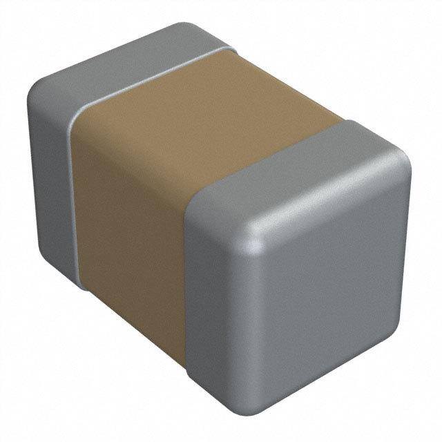
Knowles Syfer 0805J0630102JCT 是一款高可靠性多层陶瓷电容器(MLCC),规格为:0805封装、额定电压63V、标称容量1000pF(1nF)、容差±5%(J)、X7R介质(工作温度范围-55℃~+125℃)。其典型应用场景包括:

- 电源去耦与旁路:用于数字IC(如微控制器、FPGA、ADC/DAC)的电源引脚,滤除高频噪声,保障供电稳定性;
- 信号滤波与耦合:在射频前端、传感器接口、音频电路中作交流耦合或低通/高通滤波元件;
- 工业与汽车电子:凭借X7R介质的温度稳定性和Syfer(现属Knowles)的AEC-Q200兼容设计能力,适用于车载信息娱乐系统、车身控制模块及工业PLC等对可靠性要求较高的环境;
- 通信设备:在基站收发模块、Wi-Fi/蓝牙模组中用于阻抗匹配、EMI抑制和时钟滤波;
- 医疗电子:满足IEC 60601安全标准的便携式监护设备中,承担信号调理与电源净化功能。

该型号采用无铅端子、符合RoHS/REACH,具备良好抗振动与抗热冲击性能,适用于自动贴片产线。需注意避免在接近额定电压或高温高湿下长期满负荷运行,以维持寿命与参数稳定性。
| 参数 | 数值 |
| 品牌 | Syfer |
| 产品目录 | 无源元件 |
| 描述 | 多层陶瓷电容器MLCC - SMD/SMT 0805 1000pF 63V 5% Tol. C0G |
| 产品分类 | |
| 产品手册 | |
| 产品图片 |
|
| rohs | RoHS 合规性豁免 |
| 产品系列 | MLCC,多层陶瓷电容器MLCC - SMD/SMT,Syfer 0805J0630102JCT |
| 产品型号 | 0805J0630102JCT |
| 产品 | General Type MLCCs |
| 产品种类 | 多层陶瓷电容器MLCC - SMD/SMT |
| 商标 | Syfer |
| 外壳代码-in | 0805 |
| 外壳代码-mm | 2012 |
| 容差 | 5 % |
| 封装 | Reel |
| 封装/箱体 | 0805 (2012 metric) |
| 工厂包装数量 | 3000 |
| 最大工作温度 | + 125 C |
| 最小工作温度 | - 55 C |
| 温度系数/代码 | +/- 30 PPM / C |
| 电介质 | C0G (NP0) |
| 电压额定值DC | 63 V |
| 电容 | 1000 pF |
| 端接类型 | SMD/SMT |
| 类型 | Multilayer Ceramic Capacitor |


- 商务部:美国ITC正式对集成电路等产品启动337调查
- 曝三星4nm工艺存在良率问题 高通将骁龙8 Gen1或转产台积电
- 太阳诱电将投资9.5亿元在常州建新厂生产MLCC 预计2023年完工
- 英特尔发布欧洲新工厂建设计划 深化IDM 2.0 战略
- 台积电先进制程称霸业界 有大客户加持明年业绩稳了
- 达到5530亿美元!SIA预计今年全球半导体销售额将创下新高
- 英特尔拟将自动驾驶子公司Mobileye上市 估值或超500亿美元
- 三星加码芯片和SET,合并消费电子和移动部门,撤换高东真等 CEO
- 三星电子宣布重大人事变动 还合并消费电子和移动部门
- 海关总署:前11个月进口集成电路产品价值2.52万亿元 增长14.8%


PDF Datasheet 数据手册内容提取
MLC Capacitors
Introduction to Knowles Capacitors At Knowles Capacitors we make Single Layer, Multilayer, High Reliability and Precision Variable Capacitors; EMI Filters and Thin Film Devices. Our business was formed by combining Dielectric Laboratories, Johanson Manufacturing, Novacap, Syfer Technology and Voltronics into a single organization - each well-established specialty capacitor makers with a combined history of over 175 years. Our expertise is the design and manufacture of components important to engineers in applications where function and reliability are key. The markets we serve include medical implantable and medical equipment, military, aerospace/ avionics, EMI and connector filtering, oil exploration, instrumentation, industrial electronics, optical networks, telecom and automotive. We aim to be a leader in every market we serve, to the benefit of our customers and our mutual long- term success. We achieve this by: l Understanding our customers’ real needs and providing products and services to meet and exceed them. l Providing better products and services than competitors. l Investing in product development, manufacturing processes and people. l Insisting on the highest ethical standards and a business culture of trust, respect and open communication. Products in this catalogue form the basis of our ranges for ‘new designs’. However, there are legacy products from our five brands that will still be available – we ask that you contact your local Sales Office for details and ordering.
Product Selector Medical RF High Frequency Snubber Frequency Control/Tuning, Impedance Matching Capacitors Modem/Tip and Ring and Decoupling/Smoothing Filters AC Noise Removal SM and High Voltage Circuitry Leaded High Speed Decoupling Feedthrough Filtering Automotive Harsh Environments Mil/Aero is particularly recommended for these applications where possible.
X7R, C0G/NP0, High Q & Ultra-low ESR 0402 to 4040 non-magnetic termination Pages 68-71 0.1pF to 6.8µF - 16V to 3kV High Q, C0G/NP0 & Porcelain Range Pages 40-52 Ultra-low ESR MRI/Non-Magnetic C0G/NP0 Range Pages 30-33 0402 to 8060 0.47pF to 1µF - 10V to 12kV & 36-37 Class 1 Dielectrics Low DF/ESR X7R Pages 24-25 1812/2220/2225 100nF to 1µF - 250Vdc & 60-61 Class 1 Dielectrics X7R, C0G/NP0 Y2/X1, X2 Safety Certified Ranges UL/TÜV Pages 65-67 1808/1812/2211/2215/2220 High Capacitance X7R/X5R Ranges Pages 24-25 0603 to 8060 100pF to 22µF - 16V to 12kV & 60-61 Safety Certified X7R, E03 X2Y IPCs 0603 to 1812 Pages 92-95 150pF to 1.2µF - 16V to 1kV High Capacitance X7R, C0G/NP0, Y2/X1, X2 Safety Certified Ranges UL/TÜV Pages 65-67 1808/1812/2211/2215/2220 Balanced Line Capacitors X7R, C0G/NP0 Ranges Page 64 250Vac rated 50/60Hz AC Safety Certified StackiCap™ Page 62 250Vac Range 0505/1111/1825 Ranges Page 40 X7R, C0G/NP0, High Q PCB Space Saving X7R and C0G/NP0, E03 X2Y IPCs 0603 to 2220 Pages 92-95 10pF to 1.2µF Low Inductance Capacitors E01/E07/SBSGC/SBSMC X7R, C0G/NP0 Pages 92-95 0805 to 2220 - 1A to 20A Capacitive SBSP/SBSG/SBSM X7R, C0G/NP0 1206 to 2220 Pages 92-95 22pF to 470nF - 1A to 10A Capacitive/Inductive Pi AEC-Q200 E03 X2Y IPCs X7R and C0G/NP0 AEC-Q200 E01/E07 Pages 92-95 Feedthrough Capacitors Filtering Open Mode and Tandem FlexiCap™ Capacitors Page 56 with extra safe electrode design MLCC AEC-Q200 Ranges Pages 58-59 X7R, C0G/NP0 High Temperature X8R Range Page 74 Operational temperature up to 150°C Dipped Radial Leaded Capacitors Class I & II High Temperature Page 75 160ºC and 200ºC High Reliability Capacitors and Filters X7R, C0G/NP0 Pages 83-91 4.7pF to 22µF - 50V to 12kV 115Vac 400Hz range Pages 57, 72, S02A/IECQ-CECC/MIL-PRF/Burn in 94 & 95 Hi Rel X2Y IPCs
Contents General & Dielectric classifications and characteristics ............................................................................2-5 Technical Termination types including FlexiCap™ ...................................................................................6-7 Manufacturing processes .........................................................................................................8 Introduction Testing ...................................................................................................................................9 IECQ-CECC and AEC-Q200 Periodic Tests ................................................................................10 High Reliability Testing ...........................................................................................................11 Regulations and Compliance ..................................................................................................12 Explanation on Ageing of MLC ................................................................................................13 Handling, Storage, Soldering and Mechanical Precautions ....................................................14-16 Chip Marking System .............................................................................................................17 Packaging Information - Ceramic chip capacitors ................................................................18-19 Chip Dimensions ...................................................................................................................20 MLCC Ordering Chip Ordering Information .................................................................DLI..............................21 Chip Ordering Information .................................................................Novacap .....................22 Information Chip Ordering Information .................................................................Syfer ...........................23 MLC Quick Reference Guide ......................................................................Novacap-Syfer ......24-25 Industry Standard - X7R ....................................................................Novacap-Syfer ......26-29 Capacitors Industry Standard - C0G/NP0 .............................................................Novacap-Syfer ......30-33 Other Popular Sizes - X7R ..................................................................Novacap-Syfer ......34-35 Other Popular Sizes - C0G/NP0 ...........................................................Novacap-Syfer ......36-37 Standard Chip - BX ............................................................................Novacap ....................38 Improved ESR - BX & X7R ..................................................................Novacap ....................39 High Q - Q(MS) & U ranges ................................................................Syfer .....................40-42 High Q - H range - High Temperature 150ºC - X8G ..............................Syfer .................... 43-44 High Q - High Power RF - Surface Mount & Ribbon Leaded ...................Syfer .................... 45-46 High Q Porcelain - CF Series - C0G/NP0 ..............................................DLI.........................47-49 High Q Porcelain - AH Series - P90 .....................................................DLI ........................50-52 VC1 Residual - X7R ............................................................................Syfer .........................53 TCC/VCC range - (BX & BZ) X7R .........................................................Syfer .....................54-55 Open Mode and Tandem - X7R ...........................................................Syfer .........................56 IECQ-CECC range - C0G/NP0 & X7R ...................................................Syfer .........................57 Automotive Grade - AEC-Q200 range - MLC, EMI & X2Y .......................Syfer .....................58-59 High Capacitance - X7R & X5R ...........................................................Novacap ................60-61 StackiCap™ - X7R .............................................................................Syfer .........................62 NC range - X7R .................................................................................Syfer .........................63 250Vac rated 50/60Hz AC ..................................................................Syfer .........................64 250Vac Safety Certified AC .................................................................Syfer .....................65-67 Non-Magnetic - High Q, C0G/NP0 & X7R .............................................Syfer-Voltronics ....68-69 Non-Magnetic - High Power RF - High Q .............................................Syfer-Voltronics ....68-69 Non-Magnetic - High Power RF - High Q - Porcelain P90 & C0G/NP0 .....Voltronics ..............70-71 115Vac 400Hz - C0G/NP0 & X7R ........................................................Syfer .........................72 DWV (High Dielectric Withstand Voltage) range - C0G/NP0 & X7R .........Syfer .........................73 High Temperature - X8R - 150ºC ........................................................Novacap-Syfer ..........74 High Temperature - C0G/NP0 & Class II - 160ºC & 200ºC ....................Novacap ....................75 HiT range of 200ºC Caps - C0G/NP0 & X7R .........................................Novacap-Syfer ..........76 Capacitor Assemblies - ST & SM ranges - C0G/NP0 & X7R ....................Novacap ................77-81 Capacitor Assemblies - ‘Cap-Rack’ Arrays ............................................Novacap ....................82 MLC Radial Radial Leaded - Ordering Information .................................................Novacap-Syfer ..........83 Standard Radial Leaded - C0G/NP0, X7R & X8R ...................................Novacap ................84-85 Leaded Standard Radial Leaded - C0G/NP0, X7R .............................................Syfer .....................86-89 Capacitors High Temperature Radial Leaded - Epoxy Coated ................................Novacap ....................90 High Temperature Radial Leaded - Encapsulated .................................Novacap ....................91 SM EMI Filters Feedthrough Filters - E01 & E07 .........................................................Syfer .....................92-93 X2Y Integrated Passive Components - E03 ..........................................Syfer .....................94-95
Dielectric characteristics Class I Dielectrics Multilayer Ceramic Capacitors are generally divided into classes dielectric characteristics with negligible dependence of capacitance which are defined by the capacitance temperature characteristics and dissipation factor with time, voltage and frequency. They over specified temperature ranges. These are designated by alpha exhibit the following characteristics:- numeric codes. Code definitions are summarised below and are also a) Time does not significantly affect capacitance and dissipation available in the relevant national and international specifications. factor (Tan δ) – no ageing. Capacitors within this class have a dielectric constant range from b) Capacitance and dissipation factor are not affected by voltage. 10 to 100. They are used in applications which require ultra stable c) Linear temperature coefficient. Class I Dielectrics C0G/NP0 P90 Class I C0G/NP0 X8G (Porcelain) (Porcelain) High Temperature Ultra stable Ultra stable Ultra stable Ultra stable Ultra stable Dielectric IECQ-CECC - - 1B/CG - - - classifications EIA C0G/NP0 P90 C0G/NP0 X8G - - MIL - - CG (BP) - - - DLI CF AH - - - - - Novacap - - - N, RN - F D, RD Ordering code Syfer - - Q, U C H - G Voltronics F H Q - - - - Rated -55ºC to -55ºC to -55ºC to -55ºC to -55ºC to -55ºC to temperature -55ºC to +125ºC +125ºC +125ºC +125ºC +150ºC +160ºC +200ºC range Maximum No DC voltage 0 ±15 ppm/ºC 0 ±20 ppm/ºC 0 ±30 ppm/ºC 0 ±30 ppm/ºC 0 ±30 ppm/ºC 0 ±30 ppm/ºC 0 ±30 ppm/ºC capacitance applied change over temperature Rated DC - range voltage applied >50pF <0.0015 Tangent of loss ≤0.0005 <50pF ≤0.0005 ≤0.0005 @1MHz ≤0.001 angle (tan δ) @1MHz 0.0015 (15 + 0.7) @1MHz Cr @25ºC = 100GΩ or 1000ΩF Insulation Time constant @25ºC = 106 MΩ min 100GΩ or 1000s @160ºC & 200ºC = 1GΩ or resistance (Ri) (Ri x Cr) @125ºC = 105 MΩ min (whichever is the least) 10ΩF (whichever is the least) Cr <4.7pF ±0.05pF, ±0.10pF, ±0.25pF, ±0.5pF Capacitance Cr >4.7 to ±0.10pF, ±0.25pF, ±0.5pF Tolerance <10pF Cr >10pF ±1%, ±2%, ±5%, ±10% <200V 2.5 times Dielectric strength >200V to 2.5 times Rated voltage +250V Voltage applied <500V for 5 seconds. 500V to <1kV 2.5 times 1.5 times Charging current limited >1kV to 1.25 times to 50mA <1.2kV N/A maximum. >1.2kV 1.2 times Chip - - 55/125/56 - - Climatic Dipped - - - 55/125/21 - - category (IEC) Discoidal - - - 55/125/56 - - Ageing characteristic Zero (Typical) Approvals Syfer Chip - - - QC-32100 - - 2 www.knowlescapacitors.com
Dielectric characteristics Class II Dielectrics Capacitors of this type have a dielectric constant range of 1000- Capacitance and dissipation factor are affected by:- 4000 and also have a non-linear temperature characteristic which a) Time (Ageing) exhibits a dielectric constant variation of less than ±15% (2R1) b) Voltage (AC or DC) from its room temperature value, over the specified temperature c) Frequency range. Generally used for by-passing (decoupling), coupling, filtering, frequency discrimination, DC blocking and voltage transient suppression with greater volumetric efficiency than Class I units, whilst maintaining stability within defined limits. Class II Dielectrics Class II X5R X7R X8R High Temperature Stable Stable Stable Stable - 2C1 2R1 2X1 - - - IECQ-CECC Dielectric X5R - X7R - X8R - - EIA classifications - BZ - BX - - - MIL - - - - - - - DLI BW - B, RB X S G E, RE Novacap Ordering code P R X B N - X Syfer - - X - - - - Voltronics Rated -55ºC to -55ºC to -55ºC to -55ºC to -55ºC to temperature +85ºC +125ºC +150ºC +160ºC +200ºC range No DC voltage Maximum ±15% ±15% ±15% ±15% ±15% +15 -40% +15 -65% applied capacitance change over Rated DC temperature - +15 -45% - +15 -25% - - - voltage applied range ≤ 0.025 >25V <0.025 Tangent of loss <0.025 <0.025 Typical* <25V <0.035 angle (tan δ) 100GΩ or 1000s Time constant Insulation (whichever is the least) (Ri x Cr) resistance (Ri) Capacitance ±5%, ±10%, ±20% Tolerance 2.5 times <200V Dielectric strength Rated voltage +250V >200V to Voltage applied <500V for 5 seconds. Charging 1.5 times 500V to <1kV current limited to 50mA maximum. 1.2 times >1kV 55/85/56 55/125/56 55/150/56 - Chip Climatic - 55/125/21 - - Dipped category (IEC) - 55/125/56 - - Discoidal Ageing 5% <2% per time decade characteristic Typical (Typical) - QC-32100 - - - QC-32100 - Syfer Chip Approvals * Refer to page 61 for details of Dissipation Factor. www.knowlescapacitors.com 3
Dielectric characteristics Typical dielectric temperature characteristics Impedance vs Frequency Ultra Stable C0G/NP0 dielectric Porcelain C0G/NP0 & P90 Ultra Stable C0G/NP0 dielectric 1.25 100000000 10000000 1 C0G/NP0 Porcelain ms) 1000000 110npFF 1100n0FpF % 0.75 P90 Porcelain Oh 100000 e Change 00.2.55 pedance ( 10100100010000 apacitanc-0.205 Im 00.0.0111.001 0.01 0.1 1 10 100 1000 10000 C -0.5 Frequency (MHz) -0.75 Stable X7R dielectric Stable X7R dielectric -1 -55 -40 -20 0 20 40 60 80 100 125 1000000 Temperature (ºC) s) 100000 1nF 10nF C0G/NP0 m 10000 100nF 1µF h 50 ce (O 1010000 n UPPER LIMIT da 10 e p 1 25 TYPICAL LIMIT Im 0.1 C 0.01 m/° 0.001 0.01 0.1 1 10 100 1000 10000 p 0 Frequency (MHz) p C Stable X7R dielectric 10nF ∆ Stable X7R dielectric - 10nF -25 100000 LOWER LIMIT ms)ms) 10000 11820086 10281005 -50 OhOh 1000 -55 -25 0 25 50 75 100 125 e (e ( 100 Temperature (ºC) ancanc 10 X7R pedped 1 mm 20 II 0.1 15 0.01 Typical capacitance change curves 0.001 0.01 0.1 1 10 100 1000 10000 e % 10 will lie within the shown limits FFrreeqquueennccyy ((MMHHzz)) g an 5 Ch ESR vs Frequency - chips e 0 Ultra Stable C0G/NP0 dielectric nc Ultra Stable C0G/NP0 dielectric a acit -5 1000 p a -10 C 100 100pF 1nF -15 ms) 10 10nF -20 Oh 1 -55 -35 -15 5 25 45 65 85 105 125 R ( Temperature (ºC) ES 0.1 0.01 0.001 0.001 0.01 0.1 1 10 100 1000 10000 Frequency (MHz) Stable X7R dielectric Stable X7R dielectric 10000 1000 1nF 10nF ms) 11000 110µ0FnF h O 1 SR ( 0.1 E 0.01 0.001 0.0001 0.001 0.01 0.1 1 10 100 1000 10000 Frequency (MHz) 4 www.knowlescapacitors.com
Dielectric characteristics - Porcelain C0G/NP0 & P90 Typical ESR and Series Resonance characteristics CF Porcelain (C0G/NP0) and AH Porcelain (P90) DLI Cap Typical ESR Series Resonance Dielectric Series (pF) (MHz) 150 MHz 500 MHz 1 GHz 1 0.182 0.276 0.428 10300 C06CF 10 0.095 0.159 0.243 3200 0603 47 0.081 0.127 0.173 1400 1 0.073 0.089 0.146 9900 C11CF 10 0.049 0.075 0.107 3100 0505 100 0.040 0.073 0.111 970 1 0.073 0.082 0.124 9060 C17CF 10 0.065 0.098 0.136 3100 1111 100 0.041 0.070 0.102 1300 CF 1000 0.034 0.073 – 400 TCC (ppm/°C) (-55° to +125°C) 1 0.068 0.086 0.158 9060 C18CF Porcelain 10 0.058 0.087 0.118 3100 1111 (C0G/NP0) 1000 0.041 0.068 – 1000 0 ±15 10 0.072 0.113 0.164 2480 C22CF 100 0.047 0.079 0.119 1000 2225 1000 0.036 0.067 – 320 2700 0.035 – – 214 10MHz 30MHz 100MHz 10 0.121 0.054 0.037 2100 C40CF 100 0.044 0.038 0.045 680 3838 1000 0.032 0.036 0.038 210 5100 0.011 0.016 0.040 95 DLI Cap Typical ESR Series Resonance Dielectric Series (pF) (MHz) 150 MHz 500 MHz 1 GHz 1 0.067 0.08 0.136 9200 C11AH 10 0.044 0.071 0.104 3000 0505 100 0.032 0.055 0.086 1000 1 0.059 0.063 0.114 9064 C17AH 10 0.039 0.06 0.085 3100 1111 1000 0.024 0.05 0.074 1290 10 0.059 0.094 0.138 3100 AH C18AH 100 0.028 0.069 0.109 1290 TCC (ppm/°C) 1111 (-55° to +125°C) 1000 0.023 0.063 – 400 Porcelain 10 0.074 0.207 0.249 2480 (P90) C22AH 100 0.048 0.116 0.19 1000 +90 ±20 2225 1000 0.028 0.14 – 320 2700 0.027 – – 214 10MHz 30MHz 100MHz 15 0.066 0.033 0.027 2100 C40AH 100 0.018 0.026 0.052 680 3838 1000 0.009 0.017 0.033 210 5100 0.008 0.016 0.033 95 www.knowlescapacitors.com 5
Dielectric termination combinations Palladium Silver Palladium Silver Nickel Barrier (100% matte tin plating). Lead free Nickel Barrier 90/10% tin/lead Nickel Barrier Gold flash FlexiCap™ with Nickel Barrier 100% tin FlexiCap™ with Nickel Barrier 90/10% tin/lead FlexiCap™ with Copper Barrier 100% tin FlexiCap™ Ag Layer, 400-u-in Cu barrier 200-u-in Sn Plate FlexiCap™ with Copper Barrier 90/10% tin/lead Copper Barrier 100% tin Ag Layer, 400-500u-in Cu barrier, 200-u-in 90/10 Sn Plate Copper Barrier 90/10% tin/lead Solderable Silver Solderable Palladium Silver Ag termination, Ni Barrier, Heavy SnPb Plated Solder Ag termination, Enhanced Ni Barrier, Sn Plated Solder Ag termination, Enhanced Cu Barrier, Sn Plated Solder Ag Termination, Cu Barrier Layer, Heavy SnPb Plated Solder RoHS RoHS RoHS RoHS RoHS RoHS RoHS RoHS RoHS RoHS Recommended for Solder • • • • • • • • • • • • • • • • Attachment Recommended for Conductive • • • Epoxy Attachment DLI - P Z U S Q Y M - - W - V - - T E H R Novacap P PR N Y NG C D - - - B - E S K - - - - Termination ordering code: Syfer - F J A - Y H 3 - 5 2 - 4 - - - - - - Voltronics - S - - - - - 3 M - 2 W - - - - - - - Dielectric Code NP0 Porcelain - Hi Q DLI - CF • • • • • • • • • • • • P90 Porcelain - Hi Q DLI - AH • • • • • • • • • • • • • C0G - Hi Q/Low ESR Syfer - Q, U • • C0G - Hi Q/Low ESR BME Syfer - H • Novacap - N/RN • • • • • • • • • C0G/NP0 Syfer - A • • • • Syfer - C, F • • • • • C0G/NP0 - BME Syfer - G, K • • • • Novacap - M • • • • • C0G/NP0 - Syfer - C, Q • • • • Non-Mag Voltronics - Q • • • • Syfer - P • • • • • X5R Novacap - BW • • • Novacap - B/RB • • • • • • • • • X7R Syfer - E • • Syfer - X, D • • • • • Novacap - BB • • • X7R - BME Syfer - J • • • Syfer - S • • Novacap - X • • • • • • • • • BX Syfer - B • • • • • BZ Syfer - R • • • • • Novacap - C • • • • • X7R - Syfer - X • • Non-Mag Voltronics - X • • • • Novacap - S • • • • • • • • X8R Syfer - N • • • • • Syfer - T • • C0G/NP0 (160ºC) Novacap - F • • • • • • • • C0G/NP0 (200ºC) Novacap - D • • Novacap - RD • C0G/NP0 (200ºC) Syfer - G • Class II (160ºC) Novacap - G • • • • • • • • Novacap - E • • Class II (200ºC) Novacap - RE • Syfer - X • Dielectric codes in Red - AEC-Q200 qualified. Dielectric codes in Green - IECQ-CECC. 6 www.knowlescapacitors.com
FlexiCap™ overview FlexiCap™ termination working in partnership with customers world wide, to eliminate mechanical cracking. MLCCs are widely used in electronic circuit design for a multitude of applications. Their small package size, technical performance and An additional benefit of FlexiCap™ is that MLCCs can withstand suitability for automated assembly makes them the component of temperature cycling -55ºC to 125ºC in excess of 1,000 times choice for the specifier. without cracking. However, despite the technical benefits, ceramic components are FlexiCap™ termination has no adverse effect on any electrical brittle and need careful handling on the production floor. In some parameters, nor affects the operation of the MLCC in any way. circumstances they may be prone to mechanical stress damage if not used in an appropriate manner. Board flexing, depanelisation, ● Picture taken at 1,000x mounting through hole components, poor storage and automatic magnification using a SEM to demonstrate the fibrous testing may all result in cracking. nature of the FlexiCapTM Careful process control is important at all stages of circuit board termination that absorbs assembly and transportation - from component placement to increased levels of test and packaging. Any significant board flexing may result in mechanical stress. stress fractures in ceramic devices that may not always be evident during the board assembly process. Sometimes it may be the end customer who finds out - when equipment fails! Knowles has the solution - FlexiCap™ FlexiCap™ has been developed as a result of listening to customers’ Available on the following ranges: experiences of stress damage to MLCCs from many manufacturers, often caused by variations in production processes. ● All High Reliability ranges Our answer is a proprietary flexible epoxy polymer termination ● Standard and High Voltage Capacitors material, that is applied to the device under the usual nickel barrier ● Open Mode and Tandem Capacitors finish. FlexiCap™ will accommodate a greater degree of board ● Safety Certified Capacitors bending than conventional capacitors. ● Non-magnetic Capacitors Knowles FlexiCap™ termination ● 3 terminal EMI chips ● X2Y Integrated Passive Components Ranges are available with FlexiCap™ termination material offering increased reliability and superior mechanical performance (board ● X8R High Temperature capacitors flex and temperature cycling) when compared with standard Summary of PCB bend test results termination materials. Refer to Knowles application note reference The bend tests conducted on X7R have proven that the FlexiCap™ AN0001. FlexiCap™ capacitors enable the board to be bent termination withstands a greater level of mechanical stress before almost twice as much before mechanical cracking occurs. Refer to mechanical cracking occurs. application note AN0002. The AEC-Q200 test for X7R requires a bend level of 2mm minimum FlexiCap™ is also suitable for Space applications having passed and a cap change of less than 10%. thermal vacuum outgassing tests. Refer to Syfer application note reference AN0026. Product Typical bend performance under Fired ceramic X7R AEC-Q200 test conditions dielectric Standard termination 2mm to 3mm FlexiCap™ Typically 8mm to 10mm Application notes Metal electrodes FlexiCap™ may be handled, stored and transported in the same Tin outer manner as standard terminated capacitors. The requirements for layer Intermediate nickel termination mounting and soldering FlexiCap™ are the same as for standard or copper layer base SMD capacitors. For customers currently using standard terminated capacitors there FlexiCap™ MLCC cross section should be no requirement to change the assembly process when FlexiCap™ benefits converting to FlexiCap™. Based upon board bend tests in accordance with IEC 60384-1 With traditional termination materials and assembly, the chain the amount of board bending required to mechanically crack a of materials from bare PCB to soldered termination, provides no FlexiCap™ terminated capacitor is significantly increased compared flexibility. In circumstances where excessive stress is applied - the with standard terminated capacitors. weakest link fails. This means the ceramic itself, which may fail short circuit. It must be stressed however, that capacitor users must not assume that the use of FlexiCap™ terminated capacitors will totally The benefit to the user is to facilitate a wider process window - eliminate mechanical cracking. Good process controls are still giving a greater safety margin and substantially reducing the typical required for this objective to be achieved. root causes of mechanical stress cracking. FlexiCap™ may be soldered using your traditional wave or reflow solder techniques including lead free and needs no adjustment to equipment or current processes. Knowles has delivered millions of FlexiCap™ components and during that time has collected substantial test and reliability data, www.knowlescapacitors.com 7
Manufacturing processes Production process flowchart Knowles reliability grades Ceramic powder Electrode ink High reliability preparation material (space quality) Space Grade ESCC 3009(1) MIL Grade Multilayer build IECQ-CECC(2) AEC-Q200(3) Fire Standard components Standard reliability Rumble Notes: 1) Space grade tested in accordance with ESCC3009 (refer to Knowles Spec S02A 0100) or MIL Grade (in accordance with MIL-PRF-123, MIL- DPA inspection PRF-55681). 2) IECQ-CECC. The International Electrotechnical Commission (IEC) Quality Assessment System for Electronic Components. This is an internationally recognised product quality certification which provides customers with Termination assurance that the product supplied meets high quality standards. View Knowles IECQ-CECC approvals at http://www.iecq.org or at www.knowlescapacitors.com 3) AEC-Q200. Automotive Electronics Council Stress Test Qualification For Passive Components. Refer to Knowles application note reference Plating (if specified) AN0009. Printing (if specified) Knowles reliability surface mount product groups High reliability Electrical test Tandem FlexiCapTM capacitors(1) Open Mode Test verification FlexiCapTM capacitors(2) Standard FlexiCapTM capacitors(3) Standard Standard MLC capacitors(4) Additional sample reliability Rel tests (if specified) Notes: 1) “Tandem” construction capacitors, ie internally having the equivalent of 2 series capacitors. If one of these should fail short-circuit, there is still QC inspection capacitance end to end and the chip will still function as a capacitor, although capacitance maybe affected. Refer to application note AN0021. Also available qualified to AEC-Q200. 2) “Open Mode” capacitors with FlexiCapTM termination also reduce the possibility of a short circuit by utilising inset electrode margins. Refer to Additional Hi Rel application note AN0022. Also available qualified to AEC-Q200. activities 3) Multilayer capacitors with Knowles FlexiCapTM termination. By using (S02A 100% burn-in, QC insp) FlexiCapTM termination, there is a reduced possibility of the mechanical cracking occurring. 4) “Standard” capacitors includes MLCCs with tin finish over nickel but no FlexiCapTM. Packaging Finished goods store 8 www.knowlescapacitors.com
Testing Tests conducted during batch manufacture Knowles reliability SM product group S (Space grade) Standard SM IECQ-CECC / High Rel S02A AEC-Q200 capacitors MIL grade ESCC 3009 MIL-PRF-123 Solderability ● ● ● ● Resistance to soldering heat ● ● ● ● Plating thickness verification (if plated) ● ● ● ● DPA (Destructive Physical Analysis) ● ● ● ● Voltage proof test (DWV / Flash) ● ● ● ● Insulation resistance ● ● ● ● Capacitance test ● ● ● ● Dissipation factor test ● ● ● ● 100% visual inspection m m ● ● 100% burn-in. (2xRV @125ºC for 168 hours) m m m ● Load sample test @ 125ºC m m ● LAT1 & LAT2 (1000 hours) Humidity sample test. 85ºC/85%RH m m ● 240 hours Hot IR sample test m m m m Axial pull sample test (MIL-STD-123) m m m m Breakdown voltage sample test m m m m Deflection (bend) sample test m m m m SAM (Scanning Acoustic Microscopy) m m m m LAT1 (4 x adhesion, 8 x rapid temp change + LAT2 and LAT3) - - - m LAT2 (20 x 1000 hour life test + LAT3) - - - m LAT3 (6 x TC and 4 x solderability) - - - m ● Test conducted as standard. m Optional test. Please discuss with the Sales Office. www.knowlescapacitors.com 9
IECQ-CECC and AEC-Q200 Periodic tests Periodic tests conducted for IECQ-CECC and AEC-Q200 Sample Test Test Termination type Additional requirements acceptance Reference ref P N C High temperature Un-powered. 1,000 hours @ T=150ºC. MIL-STD-202 P1 All types 12 77 0 exposure Measurement at 24 ± 2 hours after test conclusion Method 108 (storage) Temperature C0G/NP0: All types 1,000 cycles -55ºC to +125ºC JESD22 P2 12 77 0 cycling X7R: Y and H only Measurement at 24 ± 2 hours after test conclusion Method JA-104 T = 24 hours/cycle. Note: Steps 7a and 7b not required. Un- Moisture MIL-STD-202 P3 All types powered. 12 77 0 resistance Method 106 Measurement at 24 ± 2 hours after test conclusion 1,000 hours 85ºC/85%RH. Rated voltage or 50V Biased MIL-STD-202 P4 All types whichever is the least and 1.5V. 12 77 0 humidity Method 103 Measurement at 24 ± 2 hours after test conclusion Operational Condition D steady state TA=125ºC at full rated. MIL-STD-202 P5 All types 12 77 0 life Measurement at 24 ± 2 hours after test conclusion Method 108 Resistance Note: Add aqueous wash chemical. MIL-STD-202 P6 All types 12 5 0 to solvents Do not use banned solvents Method 215 Mechanical C0G/NP0: All types MIL-STD-202 P7 Figure 1 of Method 213. Condition F 12 30 0 shock X7R: Y and H only Method 213 5g’s for 20 minutes, 12 cycles each of 3 orientations. Note: Use 8” x 5” PCB 0.031” thick 7 secure points on one long C0G/NP0: All types MIL-STD-202 P8 Vibration side and 2 secure points at corners of opposite sides. Parts 12 30 0 X7R: Y and H only Method 204 mounted within 2” from any secure point. Test from 10-2,000Hz Resistance to Condition B, no pre-heat of samples: MIL-STD-202 P9 All types 3 12 0 soldering heat Single wave solder - Procedure 2 Method 210 -55ºC/+125ºC. Number of cycles 300. C0G/NP0: All types MIL-STD-202 P10 Thermal shock Maximum transfer time - 20 seconds, 12 30 0 X7R: Y and H only Method 107 dwell time - 15 minutes. Air-Air Adhesion, rapid temp BS EN132100 X7R: A, F and 5N force applied for 10s, -55ºC/ +125ºC for 5 cycles, P11 change and 12 27 0 Clause 4.8, 4.12 J only damp heat cycles climatic and 4.13 sequence C0G/NP0: All types 3mm deflection Class I P12 Board flex 12 30 0 AEC-Q200-005 X7R: Y and H only 2mm deflection Class II X7R: A, F and BS EN132100 P13 Board flex 1mm deflection. 12 12 0 J only Clause 4.9 Terminal P14 All types Force of 1.8kg for 60 seconds 12 30 0 AEC-Q200-006 strength Beam load P15 All types - 12 30 0 AEC-Q200-003 test Damp heat 56 days, 40ºC / 93% RH 15x no volts, 15x 5Vdc, BS EN132100 P16 All types 12 45 0 steady state 15x rated voltage or 50V whichever is the least. Clause 4.14 Test results are available on request. P = Period in months. N = Sample size. C = Acceptance criteria. 10 www.knowlescapacitors.com
High Reliability Testing Our High Rel products are designed for optimum Military Performance Specifications reliability and are burned in at elevated voltage and temperature levels. They are 100% MIL-PRF-55681 (GROUP A) MIL-PRF-123 (GROUP A) electrically inspected to ascertain conformance to General purpose military high reliability The specification affords an increased a strict performance criteria. specification for surface mount sizes 0805 reliability level over MIL-PRF-55681 for Applications for High Reliability products include through 2225 in 50V and 100V. space, missile and other high reliability medical implanted devices, aerospace, airborne, • VOLTAGE CONDITIONING applications such as medical implantable or life support equipment. The specification various military applications, and consumer uses • 100 HRS, 2X VDCW, 125°C covers surface mount sizes 0805 through requiring safety margins not attainable with • DWV, IR, 125°C IR, CAP, DF TEST 2225 in 50V rating and various radial / axial conventional product. • VISUAL & MECH. INSPECTION leaded products in 50V, 100V and 200V We have the ability to test surface mount and (AQL SAMPLE PLAN) ratings. leaded capacitors to High Reliability standards as • SOLDERABILITY, SAMPLE 13(0) • THERMAL SHOCK, 20 CYCLES detailed below, or to customer SCD. • 8% PDA MAXIMUM • VOLTAGE CONDITIONING 168/264 HRS, Military performance specifications are designed 2X VDCW, 125°C and written for the voltage/capacitance ratings of • DWV, IR, 125°C IR, CAP, DF TEST the individual product slash numbers associated • VISUAL & MECH. INSPECTION SAMPLE with the specification. 20(0) Some of the requirements of the military • DPA(1) document may not apply to the High Reliability • PDA, 3% (0.1%), 5% (0.2%) MAX(2) product. The following details the intent of the individual military specifications available for test MIL-PRF-39014 (GROUP A) MIL-PRF-49467 (GROUP A) and the deviations that may apply. The specification covers general military General purpose military high reliability purpose radial / axial leaded and encapsulated specification for radial leaded epoxy coated. Product voltage ratings outside of the intended product in 50V, 100V, and 200V ratings. The specification covers sizes 1515 through military specification will follow the voltage test 13060 with 600V, 1kV, 2kV, 3kV, 4kV and 5kV potential outlined. • THERMAL SHOCK, 5 CYCLES ratings. • VOLTAGE CONDITIONING 96 HRS, Contact the Sales Office with any requirements or • THERMAL SHOCK, 5 CYCLES 2X VDCW, 125°C deviations that are not covered here. • VOLTAGE CONDITIONING 96 HRS, • DWV, IR, 125°C IR, CAP, DF TEST RATED VDCW, 125°C • VISUAL & MECH. INSPECTION • PARTIAL DISCHARGE (OPTION) (3) Environmental Testing (AQL SAMPLE PLAN) • DWV, IR, 125°C IR, CAP, DF TEST • SOLDERABILITY, SAMPLE 13(0) • VISUAL & MECH. INSPECTION SAMPLE We also have the capability to perform all • 8% PDA MAXIMUM 13(0) the Environmental Group B, Group C and • SOLDERABILITY, SAMPLE 5(0) Qualification testing to the referenced • 10% PDA MAXIMUM military specifications. Testing abilities include the following: MIL-PRF-49470 (DSCC 87106) MIL-PRF-38534 (GROUP A) Specification for Hybrid Microcircuits with a • Nondestructive internal examination General purpose military high reliability section for Element Evaluation on passive • Destructive physical analysis specification for stacked and leaded capacitors components. for switch mode power supplies. The There are two classification levels of • Radiographic inspection specification covers sizes 2225 through 120200 reliability. Class H is for a standard • Terminal strength in 50V, 100V, 200V and 500V ratings. military quality level. Class K is for the • Resistance to soldering heat • THERMAL SHOCK, 5 CYCLES highest reliability level intended for space application. • Voltage-temperature limits • VOLTAGE CONDITIONING 96 HRS, Knowles will perform a 100-hour burn-in • Temperature coefficient 2X VDCW(4), 125°C on all Class K products and assumes Class • Moisture resistance • DWV, IR, 125°C IR, CAP, DF TEST K Subgroup 3 samples will be unmounted • VISUAL & MECH. INSPECTION SAMPLE 13(0) and Subgroup 4 (wirebond) shall not apply • Humidity, steady state, low voltage • SOLDERABILITY, SAMPLE 5(0) unless otherwise stated. • Vibration • 10% PDA MAXIMUM • Resistance to solvents • Life TEST VOLTAGE (VDC) WVDC DWV V/C* • Thermal shock and immersion This test potential shall be used on all High <200 2.5X Rated 2.0X Rated Reliability Testing unless otherwise specified. 250 500V 400V • Low temperature storage 300 500V 400V • Barometric pressure 400 600V 500V • Shock, specified pulse 500 750V 600V • Mechanical shock 600 750V 600V • Constant acceleration *V/C Is Voltage Conditioning. >700 1.2X Rated 1.0X Rated • Wire bond evaluation • Partial discharge (corona) Notes: 1. MIL-PRF-123 DPA shall be per TABLE XIV AQL requirements unless otherwise specified. • 200°C Voltage Conditioning 2. MIL-PRF-123 allowable PDA shall be 3% overall and 0.1% in the last 48 hours for capacitance/voltage values listed in MIL-PRF-123, and be 5% overall and 0.2% in the last 48 hours for capacitance/voltage values beyond MIL-PRF-123. 3. MIL-PRF-49467 standard Group A is without Partial Discharge. Partial Discharge test is optional and must be specified. 4. MIL-PRF-49470 (DSCC 87106) 500V rated product has Voltage Conditioning at 1.2X VDCW. www.knowlescapacitors.com 11
Regulations and Compliance Release documentation Knowles reliability SM product group Standard SM AEC-Q200 S (Space grade) IECQ-CECC capacitors MIL grade High Rel S02A Certificate of conformance ● - ● ● IECQ-CECC Release certificate of conformity - ● - - Batch electrical test report m m m Included in data pack S (space grade) data documentation package - - - ● ● Release documentation supplied as standard. m Original documentation. Periodic tests conducted and reliability data availability Standard Surface Mount capacitors Example of FIT (Failure In Time) data available: Components are randomly selected on a sample basis and the 10000 following routine tests are conducted: RV 50% of RV ● Load Test. 1,000 hours @125ºC (150ºC for X8R). Applied 25% of RV 10% of RV voltage depends on components tested. 10 ● Humidity Test. 168 hours @ 85ºC/85%RH. T ● Board Deflection (bend test). FI 0.01 Test results are available on request. Conversion factors From To Operation 0.00001 25ºC 50ºC 75ºC 100ºC 125ºC FITS MTBF (hours) 109 ÷ FITS FITS MTBF (years) 109 ÷ (FITS x 8760) Component type: 0805 (C0G/NP0 and X7R). Testing location: Knowles reliability test department. FITS = Failures in 109 hours. MTBF = Mean time between failures. Results based on: 16,622,000 component test hours. REACH (Registration, Evaluation, Authorisation and for special exceptions) and those with plated terminations are restriction of Chemicals) statement suitable for soldering using common lead free solder alloys (refer to ‘Soldering Information’ for more details on soldering limitations). The main purpose of REACH is to improve the protection of human Compliance with the EU RoHS directive automatically signifies health and the environment from the risks arising from the use of compliance with some other legislation (e.g. China and Korea chemicals. RoHS). Please refer to the Knowles Capacitors Sales Office for Knowles maintains both ISO14001, Environmental Management details of compliance with other materials legislation. System and OHSAS 18001 Health and Safety Management System Breakdown of material content, SGS analysis reports and tin approvals that require and ensure compliance with corresponding whisker test results are available on request. legislation such as REACH. Most Knowles MLCC components are available with non RoHS For further information, please contact the Knowles Capacitors compliant tin lead (SnPb) solderable termination finish for exempt Sales Office at www.knowlescapacitors.com applications and where pure tin is not acceptable. Other tin free termination finishes may also be available – please refer to the RoHS compliance Knowles Capacitors Sales Office for further details. Knowles routinely monitors world wide material restrictions (e.g. Radial components have tin plated leads as standard but tin/lead is EU/China and Korea RoHS mandates) and is actively involved in available as a special option. Please refer to the radial section of the shaping future legislation. catalogue for further details. All standard C0G/NP0, X7R, X5R and High Q Knowles MLCC X8R ranges <250Vdc are not RoHS 2011/65/EU compliant. Check products are compliant with the EU RoHS directive (see below the website, www.knowlescapacitors.com for latest RoHS update. Export controls and dual-use regulations Certain Knowles catalogue components are defined as ‘dual-use’ and a capacitance value of >250nF when measured at 750Vdc items under international export controls - those that can be used and a series inductance <10nH. Components defined as dual-use for civil or military purposes which meet certain specified technical under the above criteria may require a licence for export across standards. international borders. Please contact the Sales Office for further The defining criteria for a dual use component with respect to information on specific part numbers. Knowles Capacitor products is one with a voltage rating of >750Vdc 12 www.knowlescapacitors.com
Explanation of Ageing of MLC Ageing Capacitance measurements Capacitor ageing is a term used to describe the negative, Because of ageing it is necessary to specify an age for reference logarithmic capacitance change which takes place in ceramic measurements at which the capacitance shall be within the capacitors with time. The crystalline structure for barium titanate prescribed tolerance. This is fixed at 1000 hours, since for practical based ceramics changes on passing through its Curie temperature purposes there is not much further loss of capacitance after this (known as the Curie Point) at about 125°C. This domain structure time. relaxes with time and in doing so, the dielectric constant reduces All capacitors shipped are within their specified tolerance at the logarithmically; this is known as the ageing mechanism of the standard reference age of 1000 hours after having cooled through dielectric constant. The more stable dielectrics have the lowest their Curie temperature. ageing rates. The ageing curve for any ceramic dielectric is a straight line when The ageing process is reversible and repeatable. Whenever the plotted on semi-log paper. capacitor is heated to a temperature above the Curie Point the ageing process starts again from zero. Capacitance vs time The ageing constant, or ageing rate, is defined as the percentage (Ageing X7R @ <2% per decade) loss of capacitance due to the ageing process of the dielectric which occurs during a decade of time (a tenfold increase in age) and is expressed as percent per logarithmic decade of hours. As the law of decrease of capacitance is logarithmic, this means that in a capacitor with an ageing rate of 1% per decade of time, the capacitance will decrease at a rate of: a) 1% between 1 and 10 hours % b) An additional 1% between the following 10 and 100 hours c c) An additional 1% between the following 100 and 1000 hours ∆ d) An additional 1% between the following 1000 and 10000 C0G/NP0 hours etc e) The ageing rate continues in this manner throughout the capacitor’s life. Typical values of the ageing constant for our Multilayer Ceramic 1 10 100 1000 10000 Capacitors are: Age (Hours) Dielectric class Typical values Tight tolerance One of the advantages of Knowles’ unique ‘wet process’ of Ultra Stable C0G/NP0 Negligible capacitance loss manufacture is the ability to offer capacitors with exceptionally tight through ageing capacitance tolerances. Stable X7R <2% per decade of time The accuracy of the printing screens used in the fully automated, computer controlled manufacturing process allows for tolerance as close as +/-1% on C0G/NP0 parts greater than or equal to 10pF. For capacitance values below <4.7pF, tolerances can be as tight as +/-0.05pF. www.knowlescapacitors.com 13
Mounting, Soldering, Storage & Mechanical Precautions Detailed application notes intended to guide and assist our less than the chip width. In addition, the position of the chip on the customers in using multilayer ceramic capacitors in surface board should also be considered. mount technology are available on the Knowles website www. 3-Terminal components are not specifically covered by IPC-7351, knowlescapacitors.com but recommended pad dimensions are included in the Knowles The information concentrates on the handling, mounting, catalogue / website for these components. connection, cleaning, test and re-work requirements particular to Alternative Printed Wire Board Land Patterns MLC’s for SMD technology, to ensure a suitable match between component capability and user expectation. Some extracts are Printed Wire Board land pattern design for chip components is given below. critical to ensure a reliable solder fillet, and to reduce nuisance type manufacturing problems such as component swimming and Mechanical considerations for mounted ceramic chip tombstoning. The land pattern suggested can be used for reflow capacitors and wave solder operations as noted. Land patterns constructed Due to their brittle nature, ceramic chip capacitors are more prone with these dimensions will yield optimized solder fillet formation and to excesses of mechanical stress than other components used in thus reduce the possibility of early failure.1 surface mounting. A = (Max Length) + 0.030” (.762mm)* One of the most common causes of failure is directly attributable B = (Max Width) + 0.010” (.254mm)** to bending the printed circuit board after solder attachment. C = (Min Length) – 2 (Nominal Band)*** The excessive or sudden movement of the flexible circuit board stresses the inflexible ceramic block causing a crack to appear at the weakest point, usually the ceramic/termination interface. The crack may initially be quite small and not penetrate into the inner electrodes; however, subsequent handling and rapid changes in temperature may cause the crack to enlarge. This mode of failure is often invisible to normal inspection * Add 0.030” for Wave Solder operations. techniques as the resultant cracks usually lie under the capacitor ** Replace “Max Width” with “Max Thickness” for vertical mounting. terminations but if left, can lead to catastrophic failure. More *** ”C” to be no less than 0.02”, change “A” to (Max Length) + 0.020”. importantly, mechanical cracks, unless they are severe may not be For C04 ”C” to be no less than 0.01”. detected by normal electrical testing of the completed circuit, failure only occurring at some later stage after moisture ingression. 1. Frances Classon, James Root, Martin Marietta Orlando Aerospace, “Electronics Packaging and Interconnection Handbook”. The degree of mechanical stress generated on the printed circuit board is dependent upon several factors including the board MLC Orientation - Horizontal and Vertical Mounting material and thickness; the amount of solder and land pattern. The amount of solder applied is important, as an excessive amount The orientation of the MLC relative to the ground plane affects the reduces the chip’s resistance to cracking. devices’ impedance. When the internal electrodes are parallel to the ground plane (Horizontal mounting) the impedance of the MLC It is Knowles’s experience that more than 90% are due to board resembles a folded transmission line driven from one end. depanelisation, a process where two or more circuit boards are separated after soldering is complete. Other manufacturing stages The graphs below show the modeled insertion loss and parallel that should be reviewed include: resonances of Knowles product C17AH101K-7UN-X0T with horizontal mounting (modeling can be done in CapCad). When the 1) Attaching rigid components such as connectors, relays, display internal electrodes are perpendicular to the ground plane (Vertical panels, heat sinks etc. mounting, bottom graph) the MLC impedance resembles a folded 2) Fitting conventional leaded components. Special care must transmission line driven from the center reducing resonance effects. be exercised when rigid terminals, as found on large can Horizontal Orientation electrolytic capacitors, are inserted. C17AH101K-7UN-X0T 100.0pF Temp = 25°C 0 3) Storage of boards in such a manner which allows warping. -1 4) Automatic test equipment, particularly the type employing “bed B)-2 of nails” and support pillars. S21 (d-3 5) Positioning the circuit board in its enclosure especially where -4 this is a “snap-fit”. -5 Knowles were the first MLCC manufacturer to launch a flexible -6 0 1 2 3 4 5 6 7 8 9 10 termination to significantly reduce the instances of mechanical Frequency (GHz) cracking. FlexiCap™ termination introduces a certain amount of give into the termination layer absorbing damaging stress. Unlike similar Vertical Orientation C17AH101K-7UN-X0T 100.0pF Temp = 25°C systems, FlexiCap™ does not tear under tension, but absorbs the 0 stress, so maintaining the characteristics of the MLCC. -1 SM Pad Design B)-2 Knowles conventional 2-terminal chip capacitors can generally S21 (d-3 be mounted using pad designs in accordance with IPC-7351, -4 Generic Requirements for Surface Mount Design and Land Pattern -5 Standards, but there are some other factors that have been shown -6 to reduce mechanical stress, such as reducing the pad width to 0 1 2 3 4 5 6 7 8 9 10 Frequency (GHz) 14 www.knowlescapacitors.com
Mounting, Soldering, Storage & Mechanical Precautions Knowles MLCCs are compatible with all recognised soldering / Wave soldering Surface Mount Chip Capacitors mounting methods for chip capacitors. Wave soldering is generally acceptable, but the thermal stresses Specific application notes on mounting and soldering Knowles caused by the wave have been shown to lead to potential problems components are included on the website for each brand. with larger or thicker chips. Particular care should be taken when soldering SM chips larger than size 1210 and with a thickness • For DLI brand components please see DLI application greater than 1.0mm for this reason. 0402 size components are note “Recommended Solder Attachment Techniques for MLC not suitable for wave soldering. 0402 size components can also Chip and Pre-Tinned Capacitors” located at: http://www. be susceptible to termination leaching and reflow soldering is knowlescapacitors.com/dilabs/en/gn/resources/ recommended for this size MLCC. application-notes Wave soldering exposes the devices to a large solder volume, hence • For Syfer brand components, please see Syfer application the pad size area must be restricted to accept an amount of solder note AN0028 “Soldering / Mounting Chip Capacitors, Radial which is not detrimental to the chip size utilized. Typically the pad Leaded Capacitors and EMI Filters” located at: http://www. width is 66% of the component width, and the length is .030” (.760 knowlescapacitors.com/syfer/en/gn/technical-info/ mm) longer than the termination band on the chip. An 0805 chip application-notes which is .050” wide and has a .020” termination band therefore • For Novacap brand products please refer to the appropriate requires a pad .033” wide by .050” in length. Opposing pads should application note located at: http://www.knowlescapacitors. be identical in size to preclude uneven solder fillets and mismatched com/novacap/en/gn/technical-info/application-notes surface tension forces which can misalign the device. It is preferred that the pad layout results in alignment of the long axis of the chips The volume of solder applied to the chip capacitor can influence at right angles to the solder wave, to promote even wetting of all the reliability of the device. Excessive solder can create thermal terminals. Orientation of components in line with the board travel and tensile stresses on the component which can lead to fracturing direction may require dual waves with solder turbulence to preclude of the chip or the solder joint itself. Insufficient or uneven solder cold solder joints on the trailing terminals of the devices, as these application can result in weak bonds, rotation of the device off line are blocked from full exposure to the solder by the body of the or lifting of one terminal off the pad (tombstoning). The volume of capacitor. solder is process and board pad size dependent. The pre-heat ramp should be such that the components see a Soldering methods commonly used in industry are Reflow Soldering, temperature rise of 1.5ºC to 4ºC per second as for reflow soldering. Wave Soldering and, to a lesser extent, Vapour Phase Soldering. This is to maintain temperature uniformity through the MLCC and All these methods involve thermal cycling of the components and prevent the formation of thermal gradients within the ceramic. The therefore the rate of heating and cooling must be controlled to preheat temperature should be within 120ºC maximum (100ºC preclude thermal shocking of the devices. preferred) of the maximum solder temperature to minimise thermal Without mechanical restriction, thermally induced stresses are shock. Maximum permissible wave temperature is 270ºC for SM released once the capacitor attains a steady state condition. chips. Total immersion exposure time for Sn/Ni terminations is 30s Capacitors bonded to substrates, however, will retain some stress, at a wave temperature of 260ºC. Note that for multiple soldering due primarily to the mismatch of expansion of the component to operations, including the rework, the soldering time is cumulative. the substrate; the residual stress on the chip is also influenced by The total immersion time in the solder should be kept to a the ductility and hence the ability of the bonding medium to relieve minimum. It is strongly recommended that plated terminations the stress. Unfortunately, the thermal expansion of chip capacitors are specified for wave soldering applications. PdAg termination differ significantly from those of most substrate materials. is particularly susceptible to leaching when subjected to lead Large chips are more prone to thermal shock as their greater free wave soldering and is not generally recommended for this bulk will result in sharper thermal gradients within the device application. during thermal cycling. Large units experience excessive stress if Cooling to ambient temperature should be allowed to occur processed through the fast cycles typical of solder wave or vapour naturally, particularly if larger chip sizes are being soldered. Natural phase operations. cooling allows a gradual relaxation of thermal mismatch stresses Reflow soldering Surface Mount Chip Capacitors in the solder joints. Forced cooling should be avoided as this can induce thermal breakage. Knowles recommend reflow soldering as the preferred method for mounting MLCCs. Knowles MLCCs can be reflow soldered using Vapour phase soldering Chip Capacitors a reflow profile generally as defined in IPC / JEDEC J-STD-020. Vapour phase soldering can expose capacitors to similar thermal Sn plated termination chip capacitors are compatible with both shock and stresses as wave soldering and the advice is generally conventional and lead free soldering, with peak temperatures of the same. Particular care should be taken in soldering large 260ºC to 270ºC acceptable. capacitors to avoid thermal cracks being induced and natural The heating ramp rate should be such that components see cooling should be use to allow a gradual relaxation of stresses. a temperature rise of 1.5ºC to 4ºC per seconds to maintain Hand soldering and rework of Chip Capacitors temperature uniformity through the MLCC. The time for which the solder is molten should be maintained at a minimum, so as to Attachment using a soldering iron requires extra care and is prevent solder leaching. Extended times above 230ºC can cause accepted to have a risk of cracking of the chip. Precautions include problems with oxidation of Sn plating. Use of inert atmosphere preheating of the assembly to within 100°C of the solder flow can help if this problem is encountered. PdAg terminations can temperature and the use of a fine tip iron which does not exceed 30 be particularly susceptible to leaching with lead free, tin rich watts. In no circumstances should the tip of the iron be allowed to solders and trials are recommended for this combination. Cooling contact the chip directly. to ambient temperature should be allowed to occur naturally, Knowles recommend hot air/gas as the preferred method for particularly if larger chip sizes are being soldered. Natural cooling applying heat for rework. Apply even heat surrounding the allows a gradual relaxation of thermal mismatch stresses in the component to minimise internal thermal gradients. solder joints. Forced cooling should be avoided as this can induce Minimise the rework heat duration and allow components to cool thermal breakage. naturally after soldering. www.knowlescapacitors.com 15
Mounting, Soldering, Storage & Mechanical Precautions Wave soldering Radial Leaded Chip Capacitors Transportation Radial leaded capacitors are suitable for wave soldering when Where possible, any transportation should be carried out with the mounted on the opposite side of the board to the wave. The body product in its unopened original packaging. If already opened, of radial components should not be exposed directly to the wave. any environmental control agents supplied should be returned to Maximum permissible wave temperature is 260ºC for Radial Leaded packaging and the packaging re-sealed. capacitors. Avoid paper and card as a primary means of handling, packing, Hand soldering Radial Leaded capacitors transportation and storage of loose components. Many grades have a sulphur content which will adversely affect termination Radial capacitors can be hand soldered into boards using soldering solderability. irons, provided care is taken not to touch the body of the capacitor Loose chips should always be packed with sulphur-free wadding to with the iron tip. Soldering should be carried out from the opposite prevent impact or abrasion damage during transportation. side of the board to the radial to minimise the risk of damage to the capacitor body. Where possible, a heat sink should be used Storage between the solder joint and the body, especially if longer dwell Incorrect storage of components can lead to problems for the times are required. user. Rapid tarnishing of the terminations, with an associated Solder leaching degradation of solderability, will occur if the product comes into contact with industrial gases such as sulphur dioxide and chlorine. Leaching is the term for the dissolution of silver into the solder Storage in free air, particularly moist or polluted air, can result in causing a failure of the termination system which causes increased termination oxidation. ESR, tan δ and open circuit faults, including ultimately the possibility of the chip becoming detached. Leaching occurs more Packaging should not be opened until the MLCs are required readily with higher temperature solders and solders with a high for use. If opened, the pack should be re-sealed as soon as is tin content. Pb free solders can be very prone to leaching certain practicable. Alternatively, the contents could be kept in a sealed termination systems. To prevent leaching, exercise care when container with an environmental control agent. choosing solder alloys and minimize both maximum temperature Long term storage conditions, ideally, should be temperature and dwell time with the solder molten. controlled between -5 and +40°C and humidity controlled between Plated terminations with nickel or copper anti leaching barrier layers 40 and 60% R.H. are available in a range of top coat finishes to prevent leaching Taped product should be stored out of direct sunlight, which might occurring. These finishes also include Syfer FlexiCap™ for improved promote deterioration in tape or adhesive performance. stress resistance post soldering. Product, stored under the conditions recommended above, in its “as Bonding received” packaging, has a minimum shelf life of 2 years. Hybrid assembly using conductive epoxy or wire bonding requires the use of silver palladium or gold terminations. Nickel barrier termination is not practical in these applications, as intermetallics will form between the dissimilar metals. The ESR will increase over time and may eventually break contact when exposed to temperature cycling. Cleaning Chip capacitors can withstand common agents such as water, alcohol and degreaser solvents used for cleaning boards. Ascertain that no flux residues are left on the chip surfaces as these diminish electrical performance. Handling Ceramics are dense, hard, brittle and abrasive materials. They are liable to suffer mechanical damage, in the form of chips or cracks, if improperly handled. Terminations may be abraded onto chip surfaces if loose chips are tumbled in bulk. Metallic tracks may be left on the chip surfaces which might pose a reliability hazard. Components should never be handled with fingers; perspiration and skin oils can inhibit solderability and will aggravate cleaning. Chip capacitors should never be handled with metallic instruments. Metal tweezers should never be used as these can chip the product and may leave abraded metal tracks on the product surface. Plastic or plastic coated metal types are readily available and recommended - these should be used with an absolute minimum of applied pressure. Counting or visual inspection of chip capacitors is best performed on a clean glass or hard plastic surface. If chips are dropped or subjected to rough handling, they should be visually inspected before use. Electrical inspection may also reveal gross damage via a change in capacitance, an increase in dissipation factor or a decrease either in insulation resistance or electrical strength. 16 www.knowlescapacitors.com
Chip Marking System If required, we can mark capacitors with the EIA 198 two digit code to show the capacitance value of the part. On chips larger than 3333, or A N for leaded encapsulated devices, ink marking is available. However, for A 5 chip sizes 0805 through to 3333 identification marking is accomplished 5 by using either laser or ink jet printer. This system does not degrade the ceramic surface, or induce microcracks in the part. Marking for other sizes may be available upon special request to determine if applicable; please contact the sales office. Two position alpha numeric marking Three position alpha numeric Marking is an option on Novacap and Syfer branded products and is available on chip sizes 0805 marking is available on chip sizes needs to be specified when ordering. through 3333. 1206 and larger. The marking denotes retma value The making denotes Novacap as and significant figures of capacitance vendor (N), followed by the standard (see table) eg: A5 = 100,000pF. two digit alpha numeric identification. Marking Code - value in picofarads for alpha-numeric code Number 0 1 2 3 4 5 6 7 9 A 1.0 10 100 1,000 10,000 100,000 1,000,000 10,000,000 0.1 B 1.1 11 110 1,100 11,000 110,000 1,100,000 11,000,000 0.11 C 1.2 12 120 1,200 12,000 120,000 1,200,000 12,000,000 0.12 D 1.3 13 130 1,300 13,000 130,000 1,300,000 13,000,000 0.13 E 1.5 15 150 1,500 15,000 150,000 1,500,000 15,000,000 0.15 F 1.6 16 160 1,600 16,000 160,000 1,600,000 16,000,000 0.16 G 1.8 18 180 1,800 18,000 180,000 1,800,000 18,000,000 0.18 H 2.0 20 200 2,000 20,000 200,000 2,000,000 20,000,000 0.2 J 2.2 22 220 2,200 22,000 220,000 2,200,000 22,000,000 0.22 K 2.4 24 240 2,400 24,000 240,000 2,400,000 24,000,000 0.24 L 2.7 27 270 2,700 27,000 270,000 2,700,000 27,000,000 0.27 M 3.0 30 300 3,000 30,000 300,000 3,000,000 30,000,000 0.3 N 3.3 33 330 3,300 33,000 330,000 3,000,000 33,000,000 0.33 P 3.6 36 360 3,600 36,000 360,000 3,600,000 36,000,000 0.36 Q 3.9 39 390 3,900 39,000 390,000 3,900,000 39,000,000 0.39 r R 4.3 43 430 4,300 43,000 430,000 4,300,000 43,000,000 0.43 e t t S 4.7 47 470 4,700 47,000 470,000 4,700,000 47,000,000 0.47 e L T 5.1 51 510 5,100 51,000 510,000 5,100,000 51,000,000 0.51 U 5.6 56 560 5,600 56,000 560,000 5,600,000 56,000,000 0.56 V 6.2 62 620 6,200 62,000 620,000 6,200,000 62,000,000 0.62 W 6.8 68 680 6,800 68,000 680,000 6,800,000 68,000,000 0.68 X 7.5 75 750 7,500 75,000 750,000 7,500,000 75,000,000 0.75 Y 8.2 82 820 8,200 82,000 820,000 8,200,000 82,000,000 0.82 Z 9.1 91 910 9,100 91,000 920,000 9,200,000 92,000,000 0.91 a 2.5 25 250 2,500 25,000 250,000 2,500,000 25,000,000 0.25 b 3.5 35 350 3,500 35,000 350,000 3,500,000 35,000,000 0.35 d 4.0 40 400 4,000 40,000 400,000 4,000,000 40,000,000 0.4 e 4.5 45 450 4,500 45,000 450,000 4,500,000 45,000,000 0.45 f 5.0 50 500 5,000 50,000 500,000 5,000,000 50,000,000 0.5 m 6.0 60 600 6,000 60,000 600,000 6,000,000 60,000,000 0.6 n 7.0 70 700 7,000 70,000 700,000 7,000,000 70,000,000 0.7 t 8.0 80 800 8,000 80,000 800,000 8,000,000 80,000,000 0.8 y 9.0 90 900 9,000 90,000 900,000 9,000,000 90,000,000 0.9 www.knowlescapacitors.com 17
Ceramic Chip Capacitors - Packaging information Tape and reel packing of surface mounting chip capacitors for automatic placement are in accordance with IEC60286-3. Product identifying label Dmimm e(ninsciohness ) 1.5(.06) min min T 5) Plastic carrier tape 20.2(0.79 13(0.512)± 0.5(0.02) A 60(2.36) min G Top tape Embossment 8 or 12mm 178mm (7”) or nominal 330mm (13”) dia. reel Symbol Description 178mm reel 330mm reel A Diameter 178 (7) 330 (13) Peel force G Inside width 8.4 (0.33) 12.4 (0.49) The peel force of the top sealing tape is between 0.2 and 1.0 T Outside width 14.4 (0.56) max 18.4 (0.72) max Newton at 180°. The breaking force of the carrier and sealing tape in the direction of unreeling is greater than 10 Newtons. Identification Leader and Trailer Each reel is labelled with the following information: manufacturer, END START chip size, capacitance, tolerance, rated voltage, dielectric type, batch number, date code and quantity of components. Missing components Maximum number of missing components shall be 1 per reel or 0.025% whichever is greater. There shall not be consecutive 40 empty sealed length is 20 sealed components missing from any reel for any reason. embossments minimum quantity dependent embossments minimum TRAILER COMPONENTS LEADER 400mm min. Tape dimensions Feed direction T D P 0 0 Sealing tape P 2 E F W K 0 B 0 t1 D1 P1 A0 Embossment Cavity centre lines Dimensions mm (inches) Symbol Description 8mm tape 12mm tape A Width of cavity 0 B Length of cavity Dependent on chip size to minimize rotation 0 K Depth of cavity 0 W Width of tape 8.0 (0.315) 12.0 (0.472) F Distance between drive hole centres and cavity centres 3.5 (0.138) 5.5 (0.213) E Distance between drive hole centres and tape edge 1.75 (0.069) P Distance between cavity centres 4.0 (0.156) 8.0 (0.315) 1 P Axial distance between drive hole centres and cavity centres 2.0 (0.079) 2 P Axial distance between drive hole centres 4.0 (0.156) 0 D Drive hole diameter 1.5 (0.059) 0 D Diameter of cavity piercing 1.0 (0.039) 1.5 (0.059) 1 T Carrier tape thickness 0.3 (0.012) ±0.1 (0.004) 0.4 (0.016) ±0.1 (0.004) t Top tape thickness 0.1 (0.004) max 1 18 www.knowlescapacitors.com
Ceramic Chip Capacitors - Packaging information Component orientation Outer Packaging Tape and reeling is in accordance with IEC 60286 part 3, which Outer carton dimensions mm (inches) max. defines the packaging specifications of lead less components on continuous tapes. Reel Size No. of reels L W T Notes: 1) IEC60286-3 states Ao < Bo 178 (7.0) 1 185 (7.28) 185 (7.28) 25 (0.98) (see tape dimensions on page 18). 2) Regarding the orientation of 1825 and 2225 178 (7.0) 4 190 (7.48) 195 (7.76) 75 (2.95) components, the termination bands are right to left, 330 (13.0) 1 335 (13.19) 335 (13.19) 25 (0.98) NOT front to back. Please see diagram. T Product identifying label W Orientation of 1825 & 2225 components Note: Labelling of box and L reel with bar codes (Code 39) available by arrangement. Reel quantities - Novacap, Syfer and Voltronics products Chip 0402 0505 0603 0805 1111 1206 1210 1410 1515 1808 1812 1825 2211 2215 2220 2221 2225 2520 3333 3530 3640 4540 5550 6560 7565 size Max. chip thickness mm 0.61 1.3 0.89 1.37 1.8 1.63 2.0 2.0 3.3 2.0 3.2 4.2 2.5 2.5 4.2 2.0 4.2 4.57 6.35 6.35 4.2 7.62 7.62 7.62 7.62 inches 0.02” 0.05” 0.03” 0.05” 0.07” 0.06” 0.08” 0.08” 0.13” 0.08” 0.13” 0.165” 0.1” 0.1” 0.165” 0.08” 0.165” 0.18” 0.25” 0.25” 0.165” 0.3” 0.3” 0.3” 0.3” Reel quantities 178mm (7”) 10k 2500 4000 3000 1000 2500 2000 2000 500 1500 500 500 750 500 500 1000 500 1000 - - - - - - 330mm (13”) 15k 10k 16k 12k 5000 10k 8000 8000 - 6000 2000 2000 4000 2000 2000 - 2000 1000 1000 500 500 500 500 500 200 Packaging configurations - DLI products Bulk packaging, tubs 7" 13" Chips can be supplied in rigid re-sealable plastic tubs together with 7" Reel, Reel, Reel, impact cushioning wadding. Tubs are labelled with the details: chip Chip size 8mm Tape 16mm 16mm 2" x 2" size, capacitance, tolerance, rated voltage, dielectric type, batch Tape Tape Waffle number, date code and quantity of components. Pack Style L x W Horizontal Vertical Horizontal Orientation Orientation Orientation 0.040" x C04 4000 - - - - 0.020" Product identifying label 0.060" x C06 4000 - - - 108 0.030" Caution label 0.110” x H C07 2000 - - - - 0.070” 0.080" x C08 5000 3100 - - 108 0.050" 0.055" x C11 3500 3100 - - 108 0.055" 0.110" x Dimensions mm (inches) C17 2350 750 - - 49 D 0.110" H 60 (2.36) 0.110" x C18 2350 750 - - 49 D 50 (1.97) 0.110" 0.220" x C22 500 - - - - 0.245" 0.380" x C40 250 - 250 1300 - 0.380" www.knowlescapacitors.com 19
Chip dimensions L1 T 1. For FlexiCap™ terminations, length increase by maximum 0.004” (0.1mm). 2. For special ranges, inc. High Q and Ultra-low ESR, dimensions may vary. See individual catalogue page. 3. High Q and Ultra-low ESR ranges dimensions may vary for optimum performance. 4. Non-standard thicknesses are available – consult local Knowles Capacitors Sales Office. W L2 Size Length (L1) Width (W) Max. Thickness (T) Termination Band (L2) mm ~ inches mm ~ inches mm ~ inches min (mm ~ inches) max (mm ~ inches) 0402 1.0 ± 0.10 ~ 0.04 ± 0.004 0.50 ± 0.10 ~ 0.02 ± 0.004 0.60 ~ 0.024 0.10 ~ 0.004 0.40 ~ 0.016 C04 1.057 ± 0.188 ~ 0.042 ± 0.008 0.515 ± 0.153 ~ 0.02 ± 0.006 0.64 ~ 0.025 0.097 ~ 0.004 0.427 ~ 0.017 0504 1.27 ± 0.152 ~ 0.050 ± 0.006 1.02 ± 0.152 ~ 0.04 ± 0.006 1.12 ~ 0.044 0.20 ~ 0.008 0.50 ~ 0.02 0505 1.4 +0.35 -0.25 ~ 0.055 +0.014 -0.01 1.4 ± 0.25 ~ 0.055 ± 0.01 1.27 ~ 0.05 0.13 ~ 0.005 0.5 ~ 0.02 RF0505 1.4 ± 0.13 ~ 0.055 ± 0.005 1.4 ± 0.381 ~ 0.055 ± 0.015 1.45 ~ 0.057 0.20 ~ 0.008 0.50 ~ 0.02 C11 1.477 ± 0.391 ~ 0.059 ± 0.016 1.416 ± 0.451 ~ 0.056 ± 0.018 1.334 ~ 0.053 0.193 ~ 0.008 0.733 ~ 0.029 0603 1.6 ± 0.15 ~ 0.063 ± 0.006 0.8 ± 0.15 ~ 0.032 ± 0.006 0.90 ~ 0.036 0.20 ~ 0.004 0.40 ~ 0.016 C06 1.532 ± 0.229 ~ 0.06 ± 0.009 0.77 ± 0.191 ~ 0.031 ± 0.008 0.8 ~ 0.032 0.169 ~ 0.007 0.680 ~ 0.027 C07 1.797 ± 0.470 ~ 0.071 ± 0.019 2.813 ± 0.521 ~ 0.111 ± 0.021 2.667 ~ 0.105 0.193 ~ 0.008 1.20 ~ 0.047 0805 2.0 ± 0.20 ~ 0.079 ± 0.008 1.25 ± 0.20 ~ 0.049 ± 0.008 1.37 ~ 0.054 0.25 ~ 0.010 0.75 ~ 0.030 C08 2.048 ± 0.407 ~ 0.081 ± 0.016 1.28 ± 0.267 ~ 0.051 ± 0.011 1.360 ~ 0.054 0.362 ~ 0.014 1.04 ~ 0.041 0907 2.3 ± 0.30 ~ 0.090 ± 0.012 1.8 ± 0.30 ~ 0.070 ± 0.012 1.52 ~ 0.06 0.25 ~ 0.010 0.75 ~ 0.030 1005 2.54 ± 0.203 ~ 0.100 ± 0.008 1.27 ± 0.203 ~ 0.050 ± 0.008 1.37 ~ 0.054 0.25 ~ 0.010 0.75 ~ 0.030 1111 2.79 +0.51 -0.25 ~ 0.11 +0.02 -0.01 2.79 ± 0.38 ~ 0.113 ± 0.015 1.78 ~ 0.07 0.13 ~ 0.005 0.63 ~ 0.025 RF1111 2.79 ± 0.39 ~ 0.110 ± 0.005 2.79 ± 0.381 ~ 0.110 ± 0.015 2.59 ~ 0.102 0.25 ~ 0.010 0.75 ~ 0.030 C17 2.94 ± 0.527 ~ 0.116 ± 0.021 2.813 ± 0.521 ~ 0.111 ± 0.021 2.667 ~ 0.105 0.193 ~ 0.008 1.2 ~ 0.047 C18 3.14 ± 0.727 ~ 0.124 ± 0.029 2.946 ± 0.654 ~ 0.116 ± 0.026 2.667 ~ 0.105 0.193 ~ 0.008 1.2 ~ 0.047 1206 3.2 ± 0.20 ~ 0.126 ± 0.008 1.6 ± 0.20 ~ 0.063 ± 0.008 1.70 ~ 0.068 0.25 ~ 0.010 0.75 ~ 0.030 1210 3.2 ± 0.20 ~ 0.126 ± 0.008 2.5 ± 0.20 ~ 0.098 ± 0.008 2.0 ~ 0.08 0.25 ~ 0.010 0.75 ~ 0.030 1515 3.81 ± 0.381 ~ 0.150 ± 0.015 3.81 ± 0.381 ~ 0.150 ± 0.015 3.3 ~ 0.13 0.381 ~ 0.015 1.143 ~ 0.045 1808 4.5 ± 0.35 ~ 0.180 ± 0.014 2.0 ± 0.30 ~ 0.08 ± 0.012 2.0 ~ 0.08 0.25 ~ 0.01 1.0 ~ 0.04 1812 4.5 ± 0.30 ~ 0.180 ± 0.012 3.2 ± 0.20 ~ 0.126 ± 0.008 3.2 ~ 0.125 0.25 ~ 0.010 1.143 ~ 0.045 1825 4.5 ± 0.30 ~ 0.180 ± 0.012 6.40 ± 0.40 ~ 0.252 ± 0.016 4.2 ~ 0.16 0.25 ~ 0.010 1.0 ~ 0.04 2020 5.0 ± 0.40 ~ 0.197 ± 0.016 5.0 ± 0.40 ~ 0.197 ± 0.016 4.5 ~ 0.18 0.25 ~ 0.01 1.0 ~ 0.04 2220 5.7 ± 0.40 ~ 0.225 ± 0.016 5.0 ± 0.40 ~ 0.197 ± 0.016 4.2 ~ 0.165 0.25 ~ 0.01 1.0 ~ 0.04 2211 5.7 ± 0.40 ~ 0.225 ± 0.016 2.79 ± 0.30 ~ 0.11 ± 0.012 2.5 ~ 0.1 0.25 ~ 0.01 0.8 ~ 0.03 2215 5.7 ± 0.40 ~ 0.225 ± 0.016 3.81 ± 0.35 ~ 0.35 ± 0.02 2.5 ~ 0.1 0.25 ~ 0.01 0.8 ~ 0.03 2221 5.59 ± 0.381 ~ 0.220 ± 0.015 5.33 ± 0.381 ~ 0.210 ± 0.015 2.03 ~ 0.08 0.381 ~ 0.015 1.143 ~ 0.045 2225 5.7 ± 0.40 ~ 0.225 ± 0.016 6.30 ± 0.40 ~ 0.252 ± 0.016 4.2 ~ 0.165 0.381 ~ 0.01 1.143 ~ 0.045 C22 5.734 ± 0.667 ~ 0.226 ± 0.026 6.37 ± 0.699 ~ 0.251 ± 0.028 3.467 ~ 0.137 N/A N/A 2520 6.35 ± 0.40 ~ 0.250 ± 0.016 5.08 ± 0.40 ~ 0.200 ± 0.016 4.57 ~ 0.18 0.381 ~ 0.015 1.143 ~ 0.045 RF2525 5.84 ± 0.21 ~ 0.230 ± 0.008 6.35 ± 0.381 ~ 0.250 ± 0.015 4.19 ~ 0.165 0.381 ~ 0.015 1.143 ~ 0.045 3333 8.38 ± 0.432 ~ 0.330 ± 0.017 8.38 ± 0.432 ~ 0.330 ± 0.017 6.35 ~ 0.25 0.381 ~ 0.015 1.143 ~ 0.045 3530 8.89 ± 0.457 ~ 0.350 ± 0.018 7.62 ± 0.381 ~ 0.300 ± 0.015 6.35 ~ 0.25 0.381 ~ 0.015 1.143 ~ 0.045 3640 9.2 ± 0.50 ~ 0.36 ± 0.02 10.16 ± 0.50 ~ 0.40 ± 0.02 4.5 ~ 0.18 0.50 ~ 0.02 1.50 ~ 0.06 C40 9.732 ± 0.804 ~ 0.384 ± 0.032 8.665 ± 1.737 ~ 0.381 ± 0.029 3.467 ~ 0.137 N/A N/A 4040 10.2 ± 0.508 ~ 0.400 ± 0.020 10.2 ± 0.508 ~ 0.400 ± 0.020 7.62 ~ 0.30 0.50 ~ 0.02 1.50 ~ 0.06 4540 11.4 ± 0.584 ~ 0.450 ± 0.023 10.2 ± 0.508 ~ 0.400 ± 0.020 7.62 ~ 0.30 0.50 ~ 0.02 1.50 ~ 0.06 5440 13.7 ± 0.686 ~ 0.540 ± 0.027 10.2 ± 0.508 ~ 0.400 ± 0.020 7.62 ~ 0.30 0.50 ~ 0.02 1.50 ~ 0.06 5550 14.0 ± 0.711 ~ 0.550 ± 0.028 12.7 ± 0.635 ~ 0.500 ± 0.025 7.62 ~ 0.30 0.50 ~ 0.02 1.50 ~ 0.06 6560 16.5 ± 0.838 ~ 0.650 ± 0.033 15.2 ± 0.762 ~ 0.600 ± 0.030 7.62 ~ 0.30 0.50 ~ 0.02 1.50 ~ 0.06 7565 19.1 ± 0.965 ~ 0.750 ± 0.038 16.5 ± 0.838 ~ 0.650 ± 0.033 7.62 ~ 0.30 0.50 ~ 0.02 1.50 ~ 0.06 8060 20.3 ± 0.5 ~ 0.80 ± 0.02 15.24 ± 0.50 ~ 0.60 ± 0.02 4.2 ~ 0.165 0.50 ~ 0.02 1.50 ~ 0.06 20 www.knowlescapacitors.com
Chip ordering information - DLI parts C 17 CF 620 J - 7 U N - X 0 T MLC Case Capacitance Capacitance Rated Lead Test Dielectric Termination Marking Packaging Capacitor Size Codes Tolerance voltage Type Level Voltage Case Size Codes Test Level Case Dimensions Code Value Code Testing 04 0.040" x 0.020" 5 50V X Commercial or Industrial 1 100V 06 0.060" x 0.030" Y Reduced Visual 8 150V 07 0.110" x 0.070" A MIL-PRF-55681 Group A 6 200V 08 0.080" x 0.050" 9 250V C MIL-PRF-55681 Group C 11 0.055" x 0.055" 3 300V D Customer Specified 17 0.110" x 0.110" 4 500V 18 0.110" x 0.110" 7 1kV 22 0.220" x 0.250" A 1.5kV G 2kV Laser Mark 40 0.380" x 0.380" B 2.5kV Code Laser Marking D 3.6kV H 7.2kV 0 No marking Dielectric Codes S SPECIAL 1* Single-side marked 2* Double-side marked Material Characteristics 3* Large single-side marked AH P90 High-Q Capacitance Tolerance 4* Large double-side marked CF NP0 High-Q Code Value 5* Vertical edge marked A ± 0.05pF 9 Customer Specified B ± 0.1pF *Reduces DWV Rating. Capacitance Codes C ± 0.25pF D ± 0.5pF 1st two digits are 1R0 1.0pF F ± 1% significant figures G ± 2% Packaging of capacitance, 120 12pF J ± 5% 3rd digit denotes Code Packaging K ± 10% nRu =m bdeerc iomf azle prooisn, t 471 470pF M ± 20% T Tape & Reel – Horizontal Examples: 102 1,000pF X GMV V Tape & Reel – Vertical S SPECIAL W Waffle Pack <10pF A, B, C, D B Bulk >10pF F, G, J, K, M P Plastic Box R Tube (Rail) Termination Codes S Customer Specified Code Termination System T Ag Termination, Ni Barrier Layer, Heavy SnPb Plated Solder U Ag Termination, Ni Barrier Layer, SnPb Plated Solder Leading S Ag Termination, Ni Barrier Layer, Gold Flash* Code Lead Type Z Ag Termination, Ni Barrier Layer, Sn Plated Solder* E Ag Termination, Enhanced Ni Barrier, Sn Plated Solder* A Axial Ribbon P** AgPd Termination* B Radial Ribbon Q Polymer Termination, Ni Barrier Layer, Sn Plated Solder* C Center Ribbon Y Polymer Termination, Ni Barrier Layer, SnPb Plated Solder D Specialty Customer Defined M** Polymer Termination, Cu Barrier Layer, Sn Plated Solder* E Axial Wire W** Ag Termination, Cu Barrier Layer, Sn Plated Solder* F Radial Wire H** Ag Termination, Enhanced Cu Barrier, Sn Plated Solder* N NONE V** Ag Termination, Cu Barrier Layer, SnPb Plated Solder Note: Consult your local R** Ag Termination, Cu Barrier Layer, Heavy SnPb Plated Solder Sales Office for RoHS compliant leaded ** Nonmagnetic *Indicates RoHS terminations devices. Lead Termination Codes Leads are attached with high melting point solder (HMP) at 296°C. Axial Ribbon - Code A Radial Ribbon - Code B Center Ribbon - Code C Axial Wire Lead - Code E Radial Wire Lead - Code F www.knowlescapacitors.com 21
Chip ordering information - Novacap parts XX 1206 N 472 J 101 N X050 H T M HB High High Capacitance Capacitance Special Prefix Case Size Dielectric Voltage Termination Reliability Packaging Marking Reliability Codes Tolerance Thickness Testing Test Criteria Marking Prefix Definitions None Unmarked Special Thickness M Marked None Standard chip *Marking not None Standard available on RF Improved ESR Capacitor p. 39 thickness as per sizes < 0603 ST Stacked Capacitor Assembly p. 76 - 81 Novacap catalog Note: Refer to page 17. specifications SM Stacked Hi-Rel Capacitor Assembly p. 76 - 81 CR Cap Rack Arrays p. 82 X Denotes a special thickness other Packaging than standard. Specify in inches None Bulk if required. T Tape and Reel (As shown above Dielectric Codes X = 0.050”) W Waffle Pack N C0G/NP0 Ultra Stable K R3L Ultra Stable B X7R Stable High Reliability High Reliability W X5R Stable Testing Testing Criteria X BX MIL None Standard product { HB MIL-PRF-55681 Group A BB X7R Stable BME H High Reliability Testing HV MIL-PRF-49467 Group A BW X5R Stable BME M C0G/NP0 Non Magnetic H High Temp Screening HS MIL-PRF-123 Group A C X7R Non Magnetic HK MIL-PRF-38534 Class K F C0G/NP0 High Temp. (up to 160ºC) D, RD C0G/NP0 High Temp. (up to 200ºC) Voltage Code Termination Codes S X8R High Temp. (up to 150ºC) E, RE Class II High Temp. (up to 200ºC) 1st two digits are significant, P Palladium Silver G Class II High Temp. (up to 160ºC) third digit denotes number PR Palladium Silver* of zeros. For example: RN C0G/NP0 Lead free K Solderable Palladium Silver* 160 16 Volts RB X7R Lead free N Nickel Barrier* 100% tin 101 100 Volts Y Nickel Barrier 90% tin, 10% lead 501 500 Volts NG Nickel Barrier Gold Flash* 102 1,000 Volts C FlexiCap™/Nickel Barrier* 100% tin 502 5,000 Volts D FlexiCap™/Nickel Barrier 90% tin, 10% lead B Copper Barrier* 100% tin Capacitance Codes 103 10,000 Volts E Copper Barrier 90% tin, 10% lead 1st two digits 1R0 1.0pF S Silver* are significant figures of 120 12pF *Indicates RoHS terminations capacitance, 471 470pF 3rd digit Capacitance Tolerance Codes denotes 102 1,000pF number of Code Tolerance C0G/NP0 R3L X7R BX X8R Class II X5R zeros, R = 273 0.027µF decimal point * Not RF series N M F/D, RD K B C, RE X S E/G W 474 0.47µF Examples: B ±0.10pF • • 105 1.0µF Cap. C ±0.25pF Value • • • < 10pF D ±0.50pF • • • F ±1% • • • G ±2% • • • • J ±5% • • • • •* • •* • • K ±10% • • • • • • • • • • M ±20% • • • • • • • • • 22 www.knowlescapacitors.com
Chip ordering information - Syfer parts 1210 Y 100 0103 K X T _ _ _ Capacitance Capacitance Chip Size Termination Voltage Dielectric Packaging Suffix code in picofarads (pF) Tolerance Case Code 0402 Capacitance Packaging 0603 Tolerance Codes Code 0805 Code Tolerance T 178mm (7”) reel 1206 1210 H ±0.05pF < 4.7pF R 330mm (13”) reel 1808 H ±0.05pF B Bulk pack - tubs or trays 1812 B ±0.10pF Cap. Value 1825 C ±0.25pF < 10pF 2220 D ±0.50pF 2225 F ±1% 3640 Suffix Definitions G ±2% 5550 8060 J ±5% Ca>p .1 V0aplFue Uresqeudi rfeomr espnetscific customer K ±10% PXX Palladium electrodes M ±20% Chip marking LS* *(consult sales office) Termination Codes A Nickel barrier 90/10% tin/lead Dielectric Codes F Palladium Silver* Code Dielectric Features H FlexiCap™/Nickel Barrier 90/10% tin/lead C C0G/NP0 (1B) Ultra Stable J Nickel Barrier* 100% tin H X8G Ultra Stable/High Q Y FlexiCap™/Nickel Barrier* 100% tin P X5R Stable 2 Copper Barrier* (Non Mag) 100% tin X X7R (2R1) Stable 3 FlexiCap™/Copper Barrier* (Non Mag) 100% tin J X7R (2R1)(BME) Stable 4 Copper Barrier (Non Mag) 90/10% tin/lead N X8R Stable 5 FlexiCap™/Copper Barrier (Non Mag) 90/10% tin/lead Q C0G/NP0 (1B) Ultra Stable/High Q U C0G/NP0 (1B) Ultra Stable/Ultra-low ESR *Indicates RoHS terminations A C0G/NP0 (1B) AEC -Q200 approved S X7R (2R1)(BME) AEC -Q200 approved E X7R (2R1) AEC -Q200 approved T X8R AEC -Q200 approved Voltage Code K C0G/NP0 (1B)(BME) AEC -Q200 approved Code Value Code Value Code Value F C0G/NP0 (1B) IECQ-CECC release 010 10Vdc 1K0 1kVdc A25 250Vac D X7R (2R1) IECQ-CECC release 016 16Vdc 1K2 1.2kVdc R BZ (2C1) IECQ-CECC release 025 25Vdc 1K5 1.5kVdc B BX (2X1) IECQ-CECC release 050 50Vdc 2K0 2kVdc G C0G/NP0 (1B)(BME) Ultra Stable 063 63Vdc 2K5 2.5kVdc Capacitance Code 100 100Vdc 3K0 3kVdc 200 200Vdc 4K0 4kVdc Calculation Example Capacaitance value 250 250Vdc 5K0 5kVdc 500 500Vdc 6K0 6kVdc <1.0pF Insert a P for the decimal point P300 0.3pF (values in 0.1pF steps) 630 630Vdc 8K0 8kVdc as the 1st character. 10K 10kVdc 12K 12kVdc ≥1.0pF & <10pF Insert a P for the decimal point 8P20 8.2pF (values are E24 series) as the 2nd character. ≥10pF 1st digit is 0. 2nd and 3rd digits are significant 0101 100pF (values are E24 series) figures of capacitance value. 4th digit is number of zeros. www.knowlescapacitors.com 23
MLCC standard range - 10V to 12kVdc 200/ 10V 16V 25V 50/63V 100V 500V 630V 1kV 1.2kV 1.5kV 2kV 2.5kV 3kV 4kV 5kV 6kV 8kV 10kV 12kV 250V C0G/ C0G/ C0G/ C0G/ C0G/ C0G/ C0G/ C0G/ C0G/ C0G/ C0G/ C0G/ C0G/ C0G/ C0G/ C0G/ C0G/ C0G/ C0G/ C0G/ X5R X7R X5R X7R X5R X7R X5R X7R X7R X7R X7R X7R X7R X7R X7R X7R X7R X7R X7R X7R X7R X7R X7R NP0 NP0 NP0 NP0 NP0 NP0 NP0 NP0 NP0 NP0 NP0 NP0 NP0 NP0 NP0 NP0 NP0 NP0 NP0 NP0 0.3p 120p 0.3p 120p 0.3p 120p 0.3p 120p 0.3p 120p 0402 — — - - — - - — - - — - - - - — — — — — — — — — — — — — — — — — — — — — — — — — — — — 0402 270p 5.6n 220p 4.7n 180p 4.7n 180p 4.7n 100p 2.2n 0.47p 120n 0.47p 100p 0.47p 100p 0.47p 100p 56n 0.47p 100p 0.47p 100p 0.47p 100p 0603 - - - - 120n - - — - - - - - - - - - — — — — — — — — — — — — — — — — — — — — — — — — — — 0603 3.9n 150n 2.7n 100n 2.2n 100n 1.5n 100n 68n 470p 47n 220p 10n 150p* 1.5n* 1.0p 390n 1.0p 100p 390n 1.0p 100p 270n 1.0p 100p 270n 1.0p 100p 1.0p 100p 1.0p 100p 1.0p 100p 1.0p 100p 1.0p 1.0p 1.0p 0805 - - - - - - - - - - - - - - - - - - - - - - — - — - — — — — — — — — — — — — — — — — — 0805 15n 680n 12n 330n 470n 10n 220n 390n 5.6n 220n 330n 2.2n 100n 1.0n 56n 820p 15n 820p 12n 180p 10n 120p 82p 47p 1.0p 1.2µ 1.0p 100p 1.0p 100p 1.0p 100p 560n 1.0p 100p 1.0p 100p 1.0p 100p 1.0p 100p 1.0p 100p 1.0p 100p 1.0p 100p 1.0p 100p 1.0p 100p 1.0p 100p 1206 - - - - 1.2µ - - 1.0µ - - - - - - - - - - - - - - - - - - - - - - - — — — — — — — — — — — — 1206 47n 1.5µ 33n 1.0µ 27n 820n 22n 470n 680n 8.2n 330n 3.9n 150n 2.7n 68n 2.7n 47n 1.5n 27n 680p 15n 330p 10n 220p 3.3n† 100p 2.7n† 68p 1.5n† 3.9p 1.8µ 3.9p 100p 1.8µ 3.9p 100p 1.5µ 3.9p 100p 1.2µ 3.9p 100p 3.9p 100p 3.9p 100p 3.9p 100p 3.9p 100p 3.9p 100p 3.9p 100p 3.9p 100p 3.9p 100p 3.9p 100p 1210 - - - - - - - - - - - - - - - - - - - - - - - - - - - - - - - — — — — — — — — — — — — 1210 100n 3.3µ 68n 1.5µ 2.7µ 56n 1.2µ 2.2µ 33n 1.0µ 1.5µ 18n 680n 8.2n 330n 6.8n 150n 6.8n 100n 2.2n 47n 1.5n 18n 820p 12n 470p 5.6n† 220p 4.7n† 150p 3.3n† 4.7p 1.8µ 4.7p 100p 1.8µ 4.7p 100p 4.7p 100p 820n 4.7p 100p 4.7p 100p 4.7p 100p 4.7p 100p 4.7p 100p 4.7p 100p 4.7p 100p 4.7p 100p 4.7p 100p 4.7p 100p 4.7p 100p 4.7p 100p 4.7p 100p 1808 - - - - - - - 1.5µ - - - - - - - - - - - - - - - - - - - - - - - - - - - - - — — — — — — 1808 100n 2.7µ 68n 1.5µ 2.2µ 47n 1.2µ 33n 680n 1.0µ 18n 560n 8.2n 270n 6.8n 150n 6.8n 100n 2.2n 47n 1.5n 22n 1.0n 15n 470p 5.6n† 270p 4.7n† 220p 3.3n† 120p* 2.2n*† 68p* 680p*† 47p* 390p*† 10p 3.9µ 10p 150p 3.9µ 10p 150p 2.7µ 10p 150p 2.7µ 10p 150p 10p 150p 10p 150p 10p 150p 10p 150p 10p 150p 10p 150p 10p 150p 10p 150p 10p 150p 10p 150p 10p 150p 10p 150p 1812 1812 - - - - - - - - - - - - - - - - - - - - - - - - - - - - - - - - - - - - - — — — — — — T=2.5mm 220n 10µ 180n 3.3µ 6.8µ 150n 2.2µ 4.7µ 100n 2.2µ 3.3µ 47n 1.5µ 22n 680n 15n 330n 10n 180n 6.8n 100n 4.7n 33n 2.7n 22n 1.5n 10n† 820p 8.2n† 560p 4.7n† 270p* 3.3n*† 180p* 1.2n*† 120p* 1.0n*† T=2.5mm 820n 18n 390n 12n 220n 120n 5.6n 39n 27n 12n 330p 220p 150p 1812 1812 — — — — — — — — — — — — — 27n - - - - - 8.2n - - - 3.3n - 1.8n - 1.0n — 680p — - — - — - — — — — — — — T=3.2mm 1000n 22n 470n 22n 330n 180n 6.8n 100n 56n 33n 390p* 270p* 180p* T=3.2mm 10p 5.6µ 10p 220p 5.6µ 10p 220p 4.7µ 10p 220p 2.2µ 10p 220p 10p 220p 10p 220p 10p 220p 10p 220p 10p 220p 10p 220p 10p 220p 10p 220p 10p 220p 10p 220p 10p 220p 10p 220p 1825 1825 - - - - - - - - - - - - - - - - - - - - - - - - - - - - - - - - - - - - - — — — — — — T=2.5mm 470n 15µ 330n 4.7µ 12µ 220n 3.9µ 10µ 150n 2.2µ 6.8µ 68n 1.5µ 33n 1.0µ 27n 560n 22n 200n 12n 200n 6.8n 68n 4.7n 47n 3.3n 10n 1.5n 6.8n 1.2n 3.9n 560p* 2.2n* 390p* 1.8n* 270p* 1.5n* T=2.5mm 39n 8.2n 5.6n 1.8n 1825 1825 — — — — — — — — — — — — — - — 33n — 27n — 15n — - — - — 3.9n — - — 1.5n — 680p* — 470p* — 330p* — — — — — — — T=3.2mm 47n 10n 6.8n 2.2n T=3.2mm 10p 6.8µ 10p 220p 6.8µ 10p 220p 5.6µ 10p 220p 3.9µ 10p 220p 10p 220p 10p 220p 10p 220p 10p 220p 10p 220p 10p 220p 10p 220p 10p 220p 10p 220p 10p 220p 10p 220p 10p 220p 2220 2220 - - - - - - - - - - - - - - - - - - - - - - - - - - - - - - - - - - - - - — — — — — — T=2.5mm 470n 18µ 330n 5.6µ 12µ 220n 4.7µ 10µ 150n 3.3µ 6.8µ 68n 2.2µ 33n 1.0µ 22n 560n 18n 330n 15n 120n 10n 82n 5.6n 47n 3.3n 33n 1.8n 22n† 1.5n 10n† 680p* 6.8n*† 470p* 4.7n*† 330p* 2.2n*† T=2.5mm 39n 1.2µ 27n 680n 22n 390n 18n 150n 12n 100n 6.8n 50n 3.9n 39n 2.2n 1.8n 820p 560p 390p 2220 2220 — — — — — — — — — — — — — - - - - - - - - - - - - - - - — - — - — - — - — — — — — — — T=4.2mm 56n 2.2u 39n 1µ 33n 1µ 22n 470n 15n 220n 10n 150n 5.6n 100n 3.3n 2.2n 1.2n* 820p* 560p* T=4.2mm 10p 8.2µ 10p 330p 8.2µ 10p 330p 6.8µ 10p 330p 3.9µ 10p 330p 10p 330p 10p 330p 10p 330p 10p 330p 10p 330p 10p 330p 10p 330p 10p 330p 10p 330p 10p 330p 10p 330p 10p 330p 2225 2225 - - - - - - - - - - - - - - - - - - - - - - - - - - - - - - - - - - - - - — — — — — — T=2.5mm 560n 22µ 470n 6.8µ 15µ 330n 5.6µ 12µ 220n 3.3µ 10µ 82n 2.7µ 47n 1.5µ 33n 820n 22n 390n 18n 150n 12n 100n 6.8n 68n 4.7n 33n 2.2n 12n 1.8n 8.2n 820p* 5.6n* 560p* 4.7n* 390p* 2.7n* T=2.5mm 56n 39n 27n 22n 15n 8.2n 5.6n 2.7n 2.2n 1.0n 680p 470p 2225 2225 — — — — — — — — — — — — — - — - — - — - — - — - — - — - — - — - — - — - — — — — — — — T=4.0mm 68n 47n 39n 27n 22n 12n 6.8n 3.9n 2.7n 1.5n* 1.0n* 680p* T=4.0mm 10p 470p 10p 470p 10p 470p 10p 470p 10p 470p 10p 470p 10p 470p 10p 470p 10p 470p 10p 470p 10p 470p 10p 470p 10p 470p 10p 470p 10p 470p 10p 470p 10p 470p 3640 3640 — — — — — — — — - - — - - - - - - - - - - - - - - - - - - - - - - - - - - - - - - - - T=2.5mm 330n 10µ 270n 5.6µ 120n 3.3µ 82n 1.0µ 68n 680n 47n 180n 33n 150n 22n 100n 10n 47n 6.8n 33n 4.7n 22n 1.8n 6.8n 1.5n 5.6n 1.0n 4.7n 150p 1.5n* 100p 1.0n* 68p 820p* T=2.5mm 150n 3.9µ 100n 1.2µ 82n 820n 56n 220n 39n 180n 27n 120n 12n 56n 8.2n 5.6n 2.2n 1.8n 1.2n 3640 3640 — — — — — — — — — — — — — - - - - - - - - - - - - - - - — - — - — - — - — — — — — — — T=4.0mm 180n 5.6µ 120n 2.7µ 100n 2.2µ 82n 1µ 56n 470n 39n 330n 18n 150n 12n 8.2n 3.3n 2.2n 1.5n T=4.0mm 27p 1.0n 27p 1.0n 27p 1.0n 27p 1.0n 27p 1.0n 27p 1.0n 27p 1.0n 27p 1.0n 27p 1.0n 27p 1.0n 27p 1.0n 27p 1.0n 27p 1.0n 27p 1.0n 27p 1.0n 27p 1.0n 27p 1.0n 5550 5550 — — — — — — — — - - — - - - - - - - - - - - - - - - - - - - - - - - - - - - - - - - - T=2.5mm 680n 15µ 470n 10µ 270n 5.6µ 180n 1.8µ 120n 1.2µ 82n 390n 68n 220n 39n 150n 22n 82n 12n 68n 10n 47n 4.7n 15n 2.7n 10n 1.8n 8.2n 330p 4.7n* 180p 2.2n* 120p 1.2n* T=2.5mm 220n 150n 100n 82n 47n 27n 15n 12n 5.6n 3.3n 2.2n 5550 5550 — — — — — — — — — — — — — 330n — - — - — - — - — - — - — - — - — - — - — - — — — — — — — T=4.0mm 270n 180n 150n 100n 68n 39n 22n 18n 6.8n 4.7n 3.3n T=4.0mm Note: 0505, 1111 and 2211 case sizes 47p 2.2n 47p 2.2n 47p 2.2n 47p 2.2n 47p 2.2n 47p 2.2n 47p 2.2n 47p 2.2n 47p 2.2n 47p 2.2n 47p 2.2n 47p 2.2n 47p 2.2n 47p 2.2n 47p 2.2n 47p 2.2n 47p 2.2n 8060 — — are a—vailabl—e in our— specia—lty rang—es. — - - — - - - - - - - - - - - - - - - - - - - - - - - - - - - - - - - - 8060 T=2.5mm 1.0µ 22µ 680n 15µ 390n 10µ 270n 3.3µ 220n 2.2µ 150n 1.0µ 100n 470n 68n 330n 39n 150n 22n 100n 15n 82n 8.2n 33n 5.6n 22n 3.9n 15n 680p 6.8n* 470p 4.7n* 220p 2.2n* T=2.5mm Please refer to the relevant sections of this catalogue for more details. 470n 330n 270n 180n 120n 82n 47n 27n 18n 10n 6.8n 4.7n 8060 8060 — — — — — — — — — — — — — - — - — - — - — - — - — - — - — - — - — - — - — — — — — — — T=4.0mm 560n 470n 390n 270n 180n 120n 68n 39n 27n 15n 10n 6.8n T=4.0mm 200/ 10V 16V 25V 50/63V 100V 500V 630V 1kV 1.2kV 1.5kV 2kV 2.5kV 3kV 4kV 5kV 6kV 8kV 10kV 12kV 250V 24 www.knowlescapacitors.com
Notes: 1) Capacitance in F - min value above max value. 2) *These parts may require conformal coating post soldering. 3) T = Maximum thickness. 4) †Higher capacitance values available from the NC range - see page 63. 5) StackiCap™ high capacitance versions are now available. Please refer to datasheet. 6) Parts in this range may be defined as dual-use under export control legislation as such may be subject to export licence restrictions. Please refer to p12 for more information on the dual-use regulations and contact the Sales Office for further information on specific part numbers. 200/ 10V 16V 25V 50/63V 100V 500V 630V 1kV 1.2kV 1.5kV 2kV 2.5kV 3kV 4kV 5kV 6kV 8kV 10kV 12kV 250V C0G/ C0G/ C0G/ C0G/ C0G/ C0G/ C0G/ C0G/ C0G/ C0G/ C0G/ C0G/ C0G/ C0G/ C0G/ C0G/ C0G/ C0G/ C0G/ C0G/ X5R X7R X5R X7R X5R X7R X5R X7R X7R X7R X7R X7R X7R X7R X7R X7R X7R X7R X7R X7R X7R X7R X7R NP0 NP0 NP0 NP0 NP0 NP0 NP0 NP0 NP0 NP0 NP0 NP0 NP0 NP0 NP0 NP0 NP0 NP0 NP0 NP0 0.3p 120p 0.3p 120p 0.3p 120p 0.3p 120p 0.3p 120p 0402 — — - - — - - — - - — - - - - — — — — — — — — — — — — — — — — — — — — — — — — — — — — 0402 270p 5.6n 220p 4.7n 180p 4.7n 180p 4.7n 100p 2.2n 0.47p 120n 0.47p 100p 0.47p 100p 0.47p 100p 56n 0.47p 100p 0.47p 100p 0.47p 100p 0603 - - - - 120n - - — - - - - - - - - - — — — — — — — — — — — — — — — — — — — — — — — — — — 0603 3.9n 150n 2.7n 100n 2.2n 100n 1.5n 100n 68n 470p 47n 220p 10n 150p* 1.5n* 1.0p 390n 1.0p 100p 390n 1.0p 100p 270n 1.0p 100p 270n 1.0p 100p 1.0p 100p 1.0p 100p 1.0p 100p 1.0p 100p 1.0p 1.0p 1.0p 0805 - - - - - - - - - - - - - - - - - - - - - - — - — - — — — — — — — — — — — — — — — — — 0805 15n 680n 12n 330n 470n 10n 220n 390n 5.6n 220n 330n 2.2n 100n 1.0n 56n 820p 15n 820p 12n 180p 10n 120p 82p 47p 1.0p 1.2µ 1.0p 100p 1.0p 100p 1.0p 100p 560n 1.0p 100p 1.0p 100p 1.0p 100p 1.0p 100p 1.0p 100p 1.0p 100p 1.0p 100p 1.0p 100p 1.0p 100p 1.0p 100p 1206 - - - - 1.2µ - - 1.0µ - - - - - - - - - - - - - - - - - - - - - - - — — — — — — — — — — — — 1206 47n 1.5µ 33n 1.0µ 27n 820n 22n 470n 680n 8.2n 330n 3.9n 150n 2.7n 68n 2.7n 47n 1.5n 27n 680p 15n 330p 10n 220p 3.3n† 100p 2.7n† 68p 1.5n† 3.9p 1.8µ 3.9p 100p 1.8µ 3.9p 100p 1.5µ 3.9p 100p 1.2µ 3.9p 100p 3.9p 100p 3.9p 100p 3.9p 100p 3.9p 100p 3.9p 100p 3.9p 100p 3.9p 100p 3.9p 100p 3.9p 100p 1210 - - - - - - - - - - - - - - - - - - - - - - - - - - - - - - - — — — — — — — — — — — — 1210 100n 3.3µ 68n 1.5µ 2.7µ 56n 1.2µ 2.2µ 33n 1.0µ 1.5µ 18n 680n 8.2n 330n 6.8n 150n 6.8n 100n 2.2n 47n 1.5n 18n 820p 12n 470p 5.6n† 220p 4.7n† 150p 3.3n† 4.7p 1.8µ 4.7p 100p 1.8µ 4.7p 100p 4.7p 100p 820n 4.7p 100p 4.7p 100p 4.7p 100p 4.7p 100p 4.7p 100p 4.7p 100p 4.7p 100p 4.7p 100p 4.7p 100p 4.7p 100p 4.7p 100p 4.7p 100p 4.7p 100p 1808 - - - - - - - 1.5µ - - - - - - - - - - - - - - - - - - - - - - - - - - - - - — — — — — — 1808 100n 2.7µ 68n 1.5µ 2.2µ 47n 1.2µ 33n 680n 1.0µ 18n 560n 8.2n 270n 6.8n 150n 6.8n 100n 2.2n 47n 1.5n 22n 1.0n 15n 470p 5.6n† 270p 4.7n† 220p 3.3n† 120p* 2.2n*† 68p* 680p*† 47p* 390p*† 10p 3.9µ 10p 150p 3.9µ 10p 150p 2.7µ 10p 150p 2.7µ 10p 150p 10p 150p 10p 150p 10p 150p 10p 150p 10p 150p 10p 150p 10p 150p 10p 150p 10p 150p 10p 150p 10p 150p 10p 150p 1812 1812 - - - - - - - - - - - - - - - - - - - - - - - - - - - - - - - - - - - - - — — — — — — T=2.5mm 220n 10µ 180n 3.3µ 6.8µ 150n 2.2µ 4.7µ 100n 2.2µ 3.3µ 47n 1.5µ 22n 680n 15n 330n 10n 180n 6.8n 100n 4.7n 33n 2.7n 22n 1.5n 10n† 820p 8.2n† 560p 4.7n† 270p* 3.3n*† 180p* 1.2n*† 120p* 1.0n*† T=2.5mm 820n 18n 390n 12n 220n 120n 5.6n 39n 27n 12n 330p 220p 150p 1812 1812 — — — — — — — — — — — — — 27n - - - - - 8.2n - - - 3.3n - 1.8n - 1.0n — 680p — - — - — - — — — — — — — T=3.2mm 1000n 22n 470n 22n 330n 180n 6.8n 100n 56n 33n 390p* 270p* 180p* T=3.2mm 10p 5.6µ 10p 220p 5.6µ 10p 220p 4.7µ 10p 220p 2.2µ 10p 220p 10p 220p 10p 220p 10p 220p 10p 220p 10p 220p 10p 220p 10p 220p 10p 220p 10p 220p 10p 220p 10p 220p 10p 220p 1825 1825 - - - - - - - - - - - - - - - - - - - - - - - - - - - - - - - - - - - - - — — — — — — T=2.5mm 470n 15µ 330n 4.7µ 12µ 220n 3.9µ 10µ 150n 2.2µ 6.8µ 68n 1.5µ 33n 1.0µ 27n 560n 22n 200n 12n 200n 6.8n 68n 4.7n 47n 3.3n 10n 1.5n 6.8n 1.2n 3.9n 560p* 2.2n* 390p* 1.8n* 270p* 1.5n* T=2.5mm 39n 8.2n 5.6n 1.8n 1825 1825 — — — — — — — — — — — — — - — 33n — 27n — 15n — - — - — 3.9n — - — 1.5n — 680p* — 470p* — 330p* — — — — — — — T=3.2mm 47n 10n 6.8n 2.2n T=3.2mm 10p 6.8µ 10p 220p 6.8µ 10p 220p 5.6µ 10p 220p 3.9µ 10p 220p 10p 220p 10p 220p 10p 220p 10p 220p 10p 220p 10p 220p 10p 220p 10p 220p 10p 220p 10p 220p 10p 220p 10p 220p 2220 2220 - - - - - - - - - - - - - - - - - - - - - - - - - - - - - - - - - - - - - — — — — — — T=2.5mm 470n 18µ 330n 5.6µ 12µ 220n 4.7µ 10µ 150n 3.3µ 6.8µ 68n 2.2µ 33n 1.0µ 22n 560n 18n 330n 15n 120n 10n 82n 5.6n 47n 3.3n 33n 1.8n 22n† 1.5n 10n† 680p* 6.8n*† 470p* 4.7n*† 330p* 2.2n*† T=2.5mm 39n 1.2µ 27n 680n 22n 390n 18n 150n 12n 100n 6.8n 50n 3.9n 39n 2.2n 1.8n 820p 560p 390p 2220 2220 — — — — — — — — — — — — — - - - - - - - - - - - - - - - — - — - — - — - — — — — — — — T=4.2mm 56n 2.2u 39n 1µ 33n 1µ 22n 470n 15n 220n 10n 150n 5.6n 100n 3.3n 2.2n 1.2n* 820p* 560p* T=4.2mm 10p 8.2µ 10p 330p 8.2µ 10p 330p 6.8µ 10p 330p 3.9µ 10p 330p 10p 330p 10p 330p 10p 330p 10p 330p 10p 330p 10p 330p 10p 330p 10p 330p 10p 330p 10p 330p 10p 330p 10p 330p 2225 2225 - - - - - - - - - - - - - - - - - - - - - - - - - - - - - - - - - - - - - — — — — — — T=2.5mm 560n 22µ 470n 6.8µ 15µ 330n 5.6µ 12µ 220n 3.3µ 10µ 82n 2.7µ 47n 1.5µ 33n 820n 22n 390n 18n 150n 12n 100n 6.8n 68n 4.7n 33n 2.2n 12n 1.8n 8.2n 820p* 5.6n* 560p* 4.7n* 390p* 2.7n* T=2.5mm 56n 39n 27n 22n 15n 8.2n 5.6n 2.7n 2.2n 1.0n 680p 470p 2225 2225 — — — — — — — — — — — — — - — - — - — - — - — - — - — - — - — - — - — - — — — — — — — T=4.0mm 68n 47n 39n 27n 22n 12n 6.8n 3.9n 2.7n 1.5n* 1.0n* 680p* T=4.0mm 10p 470p 10p 470p 10p 470p 10p 470p 10p 470p 10p 470p 10p 470p 10p 470p 10p 470p 10p 470p 10p 470p 10p 470p 10p 470p 10p 470p 10p 470p 10p 470p 10p 470p 3640 3640 — — — — — — — — - - — - - - - - - - - - - - - - - - - - - - - - - - - - - - - - - - - T=2.5mm 330n 10µ 270n 5.6µ 120n 3.3µ 82n 1.0µ 68n 680n 47n 180n 33n 150n 22n 100n 10n 47n 6.8n 33n 4.7n 22n 1.8n 6.8n 1.5n 5.6n 1.0n 4.7n 150p 1.5n* 100p 1.0n* 68p 820p* T=2.5mm 150n 3.9µ 100n 1.2µ 82n 820n 56n 220n 39n 180n 27n 120n 12n 56n 8.2n 5.6n 2.2n 1.8n 1.2n 3640 3640 — — — — — — — — — — — — — - - - - - - - - - - - - - - - — - — - — - — - — — — — — — — T=4.0mm 180n 5.6µ 120n 2.7µ 100n 2.2µ 82n 1µ 56n 470n 39n 330n 18n 150n 12n 8.2n 3.3n 2.2n 1.5n T=4.0mm 27p 1.0n 27p 1.0n 27p 1.0n 27p 1.0n 27p 1.0n 27p 1.0n 27p 1.0n 27p 1.0n 27p 1.0n 27p 1.0n 27p 1.0n 27p 1.0n 27p 1.0n 27p 1.0n 27p 1.0n 27p 1.0n 27p 1.0n 5550 5550 — — — — — — — — - - — - - - - - - - - - - - - - - - - - - - - - - - - - - - - - - - - T=2.5mm 680n 15µ 470n 10µ 270n 5.6µ 180n 1.8µ 120n 1.2µ 82n 390n 68n 220n 39n 150n 22n 82n 12n 68n 10n 47n 4.7n 15n 2.7n 10n 1.8n 8.2n 330p 4.7n* 180p 2.2n* 120p 1.2n* T=2.5mm 220n 150n 100n 82n 47n 27n 15n 12n 5.6n 3.3n 2.2n 5550 5550 — — — — — — — — — — — — — 330n — - — - — - — - — - — - — - — - — - — - — - — — — — — — — T=4.0mm 270n 180n 150n 100n 68n 39n 22n 18n 6.8n 4.7n 3.3n T=4.0mm 47p 2.2n 47p 2.2n 47p 2.2n 47p 2.2n 47p 2.2n 47p 2.2n 47p 2.2n 47p 2.2n 47p 2.2n 47p 2.2n 47p 2.2n 47p 2.2n 47p 2.2n 47p 2.2n 47p 2.2n 47p 2.2n 47p 2.2n 8060 8060 — — — — — — — — - - — - - - - - - - - - - - - - - - - - - - - - - - - - - - - - - - - T=2.5mm 1.0µ 22µ 680n 15µ 390n 10µ 270n 3.3µ 220n 2.2µ 150n 1.0µ 100n 470n 68n 330n 39n 150n 22n 100n 15n 82n 8.2n 33n 5.6n 22n 3.9n 15n 680p 6.8n* 470p 4.7n* 220p 2.2n* T=2.5mm 470n 330n 270n 180n 120n 82n 47n 27n 18n 10n 6.8n 4.7n 8060 8060 — — — — — — — — — — — — — - — - — - — - — - — - — - — - — - — - — - — - — — — — — — — T=4.0mm 560n 470n 390n 270n 180n 120n 68n 39n 27n 15n 10n 6.8n T=4.0mm 200/ 10V 16V 25V 50/63V 100V 500V 630V 1kV 1.2kV 1.5kV 2kV 2.5kV 3kV 4kV 5kV 6kV 8kV 10kV 12kV 250V www.knowlescapacitors.com 25
Industry Standard - MLC chip range - X7R Capacitance Code 0402 0603 0805 1206 Capacitance Code 111102580000p F 111102581111 16V25V50/63V100V200/250V 16V25V50/63V100V200/250V500V 16V25V50/63V100V200/250V500V630V1kV 16V25V50/63V100V200/250V500V630V1kV1.2kV1.5kV2kV2.5kV3kV 111102580000p F 111102581111 111102580000 pF 111102581111 111102580000 pF 111102581111 220 221 220 221 220 221 220 221 270 271 270 271 270 271 270 271 330 331 330 331 330 331 330 331 390 391 390 391 390 391 390 391 470 471 470 471 470 471 470 471 560 561 560 561 560 561 560 561 R 680 681 680 681 680 681 680 681 820 821 820 821 820 821 820 821 7 1.0nF 102 1.0nF 102 1.0nF 102 1.0nF 102 X 111223345.........772582396 111223354725827396222222222 5.6nF4.7nF4.7nF (50V)4.7nF2.2nF (200V) 1.5nF † 3.3nF† 2.7nF† 1.5nF 111223345.........772582396 111223354258273976222222222 111223345.........772582396 411122335725827396222222222 111223354.........772582396 411122335725827396222222222 6811112..0258282n F 681112182258202233333 10nF 15nF12nF10nF * 27nF15nF10nF 6811121..2582082n F 681112182258202233333 6811112..0258282n F 681112182258202233333 6811121..2582082n F 681112182258202233333 27 273 * 27 273 27 273 27 273 3339 333933 47nF 47nF 3339 333933 3339 333933 3339 333933 47 473 47 473 47 473 47 473 56 563 68nF 56 563 56 563 56 563 6811820200 n F 681182023344 100nF100nF100nFt 100nF56nF 150nF 68118202 00n F 681182023344 6811820200 nF 681182023344 68118202 00 nF 681182023344 112582000 112582444 220nF220nF 112582000 112582444 112582000 112582444 112582000 112582444 237300 237344 330nF 330nF 237300 237344 237300 237344 237300 237344 390 394 390 394 390 394 390 394 470 474 470 474 470 474 470 474 5681682.0000µ F 568168204445 1.0µF820nF470nF 5681682.0000µ F 568168204445 5681682.0000µ F 568168204445 5681682.0000µ F 568168204445 1.2 125 1.2 125 1.2 125 1.2 125 1.5 155 1.5 155 1.5 155 1.5 155 1.8 185 1.8 185 1.8 185 1.8 185 2.2 225 2.2 225 2.2 225 2.2 225 2.7 275 X7R 2.7 275 2.7 275 2.7 275 3.3 335 3.3 335 3.3 335 3.3 335 3.9 395 3.9 395 3.9 395 3.9 395 4.7 475 4.7 475 4.7 475 4.7 475 5.6 565 5.6 565 5.6 565 5.6 565 6.8 685 6.8 685 6.8 685 6.8 685 8.2 825 8.2 825 8.2 825 8.2 825 10µF 106 10µF 106 10µF 106 10µF 106 12 126 12 126 12 126 12 126 15 156 15 156 15 156 15 156 18 186 18 186 18 186 18 186 22µF 226 22µF 226 22µF 226 22µF 226 * StackiCap™ high capacitance versions available from the StackiCap™ range - see page 62 for details. For 0504, 0907, 1005, 2020, † Higher capacitance values available from the NC capacitor range 2221, 4040, 5440 and 43100 - see page 63 for details. range information please ** Max. capacitance of 27nF, has increased chip length of 3.5mm. refer to your local Knowles Reduced max. cap value of 22nF, for standard dimension. Sales Office. l = AEC-Q200 approved parts - maximum values. t For 0603 50/63V values from 68nF to 100nF should be ordered with FB6 suffix. 26 www.knowlescapacitors.com
10Vdc to 12kVdc Capacitance Code 1210 1808 Capacitance Code 111025000 pF 111025111 111025000 pF 111025111 111025000p F 111025111 16V25V50/63V100V200/250V500V630V1kV1.2kV1.5kV2kV2.5kV3kV 16V25V50/63V100V200/250V500V630V1kV1.2kV1.5kV2kV2.5kV3kV4kV5kV6kV 111025000p F 111025111 180 181 180 181 180 181 180 181 220 221 220 221 220 221 220 221 270 271 270 271 270 271 270 271 333900 333911 333900 333911 333900 333911 390pF 333900 333911 470 471 470 471 470 471 470 471 566800 566811 566800 566811 566800 566811 680pF 566800 566811 R 820 821 820 821 820 821 820 821 1.0nF 102 1.0nF 102 1.0nF 102 1.0nF 102 7 1.2 122 1.2 122 1.2 122 1.2 122 X 1.5 152 1.5 152 1.5 152 1.5 152 12..82 128222 12..82 128222 12..82 128222 † 2.2nF 12..82 128222 23345.....77396 423357739622222 23345.....77396 423357739622222 23345.....77396 233547739622222 † 5.6nF† 4.7nF† 3.3nF † 5.6nF† 4.7nF† 3.3nF 23354.....77396 233547396722222 6.8 682 6.8 682 6.8 682 6.8 682 8.2 822 8.2 822 8.2 822 8.2 822 111025n F 111250333 111250n F 111250333 111025n F 111250333 18nF12nF 15nF 111250n F 111250333 1282 128233 1282 128233 1282 128233 22nF 1282 128233 27 273 27 273 27 273 27 273 33 333 33 333 33 333 33 333 3497 349733 3497 349733 3497 349733 47nF 47nF 3497 349733 56 563 56 563 56 563 56 563 6811182025000 nF 681118202533444 6811182025 000 nF 681118202533444 6811182025000 n F 681118202533444 150nF100nF 150nF100nF 6811182025 000n F 681118202533444 180 184 180 184 180 184 180 184 222700 222744 222700 222744 222700 222744 330nF 270nF 222700 222744 330 334 330 334 330 334 330 334 390 394 390 394 390 394 390 394 456876820000 456876824444 456876820000 456876824444 456876820000 456876824444 1.0µF680nF 680nF560nF 456876820000 456876824444 111...025µ F 111250555 111...250µ F 111250555 111...025µ F 111250555 1.5µF1.2µF 1.5µF1.2µF 111...250µ F 111250555 1.8 185 1.8 185 1.8 185 1.8 185 2.2 225 2.2 225 2.2 225 2.2 225 2.7 275 2.7 275 2.7 275 2.7 275 3.3 335 3.3 335 3.3 335 3.3 335 3.9 395 3.9 395 3.9 395 3.9 395 4.7 475 4.7 475 4.7 475 4.7 475 5.6 565 5.6 565 5.6 565 5.6 565 6.8 685 6.8 685 6.8 685 6.8 685 8.2 825 8.2 825 8.2 825 8.2 825 10µF 106 10µF 106 10µF 106 10µF 106 12 126 12 126 12 126 12 126 15 156 15 156 15 156 15 156 X7R 18 186 18 186 18 186 18 186 22µF 226 22µF 226 22µF 226 22µF 226 www.knowlescapacitors.com 27
Industry Standard - MLC chip range - X7R Capacitance Code 1812 1825 Capacitance Code 100pF 101 100pF 101 100pF 101 100pF 101 120 121 120 121 120 121 120 121 112235827300000 112235827311111 16V25V50/63V100V200/250V500V630V1kV1.2kV1.5kV2kV2.5kV3kV4kV5kV6kV 16V25V50/63V100V200/250V500V630V1kV1.2kV1.5kV2kV2.5kV3kV4kV5kV6kV 112235827300000 112235827311111 112235827300000 112235827311111 112235827300000 112235827311111 390 391 390 391 390 391 390 391 470 471 470 471 470 471 470 471 560 561 560 561 560 561 560 561 R 680 681 680 681 680 681 680 681 X7 8111122.....025820n F 111281258220222212 1.2nF1.0nF 2.2nF1.8nF1.5nF 111281....2.258200n F 111281258220222212 8111122.....025820n F 111281258220222212 111281....2.258200n F 111281258220222212 2334....7739 233477392222 † 4.7nF† 3.3nF 3.9nF 2334....7739 233473972222 2334....7739 423377392222 2334....7739 423377392222 568...682 568682222 † 10nF† 8.2nF 10nF6.8nF 568...682 568682222 568...682 568682222 568...682 568682222 10nF 103 10nF 103 10nF 103 10nF 103 12 123 12 123 12 123 12 123 15 153 15 153 15 153 15 153 18 183 22nF 18 183 18 183 18 183 22 223 22 223 22 223 22 223 27 273 33nF 27 273 27 273 27 273 33 333 * 33 333 33 333 33 333 39 393 47nF 39 393 39 393 39 393 47 473 47 473 47 473 47 473 56 563 * 68nF 56 563 56 563 56 563 68 683 68 683 68 683 68 683 81111202580000 n F 811112025834444 180nF100nF** 200nF200nF 8111120258 0000n F 811112025834444 81111202580000 nF 811112025834444 8111120258 0000 nF 811112025834444 222700 222744 330nF 222700 222744 222700 222744 222700 222744 334397000 334397444 680nF ** 560nF 334397000 334397444 334397000 334397444 334397000 334397444 560 564 560 564 560 564 560 564 688200 688244 1.0µF 688200 688244 688200 688244 688200 688244 11112.....02582µ F 111212582055555 2.2µ F2.2µF1.5µF * 2.2µF1.5µF 11121.....25820µ F 111212582055555 11112.....02582µ F 111212582055555 11121.....25820µ F 111212582055555 2334....7739 233477395555 3.3µF 4.7µF3.9µF 2334....7739 233473975555 2334....7739 423377395555 2334....7739 423377395555 5.6 565 5.6 565 5.6 565 5.6 565 6.8 685 6.8 685 6.8 685 6.8 685 8.2 825 X7R 8.2 825 8.2 825 8.2 825 10µF 106 10µF 106 10µF 106 10µF 106 12 126 12 126 12 126 12 126 15 156 15 156 15 156 15 156 18 186 18 186 18 186 18 186 22µF 226 22µF 226 22µF 226 22µF 226 * StackiCap™ high capacitance versions available from the For 0504, 0907, 1005, 2020, StackiCap™ range - see page 62 for details. 2221, 4040, 5440 and 43100 † Higher capacitance values available from the NC capacitor range - see page 63 for details. range information please refer to your local Knowles l = AEC-Q200 approved parts - maximum values. Sales Office. 28 www.knowlescapacitors.com
10Vdc to 12kVdc Capacitance Code 2220 2225 Capacitance Code 100pF 101 100pF 101 100pF 101 100pF 101 120 121 120 121 120 121 120 121 150 151 150 151 150 151 150 151 180 181 180 181 180 181 180 181 223342739700000 223342739711111 223342739700000 223342739711111 223342739700000 223342739711111 16V25V50/63V100V200/250V500V630V1kV1.2kV1.5kV2kV2.5kV3kV4kV5kV6kV 16V25V50/63V100V200/250V500V630V1kV1.2kV1.5kV2kV2.5kV3kV4kV5kV6kV 223342739700000 223342739711111 560 561 560 561 560 561 560 561 680 681 680 681 680 681 680 681 R 820 821 820 821 820 821 820 821 1.0nF 102 1.0nF 102 1.0nF 102 1.0nF 102 7 1.2 122 1.2 122 1.2 122 1.2 122 X 1.5 152 1.5 152 1.5 152 1.5 152 122...782 122827222 122...782 122827222 122...782 122827222 2.2nF 2.7nF 122...782 122827222 3.3 332 3.3 332 3.3 332 3.3 332 3456811.....0279682n F 435681179682202222233 3456811.....2079682n F 435681179682202222233 3456811.....0279682n F 356814179682202222233 † 10nF† 6.8nF† 4.7nF 12nF8.2nF5.6nF4.7nF 3456811.....2079682n F 356814197682202222233 15 153 15 153 15 153 15 153 122827 122827333 122827 122827333 122827 122827333 33nF† 22nF 33nF 122827 122827333 3339 333933 3339 333933 3339 333933 47nF 3339 333933 47 473 47 473 47 473 47 473 568116820200 nF 568116820233344 5681168202 00 nF 568116820233344 568116820200 n F 568116820233344 120nF82nF * 150nF100nF68nF 5681168202 00n F 568116820233344 150 154 150 154 150 154 * 150 154 180 184 180 184 180 184 180 184 223273000 223273444 223273000 223273444 223273000 223273444 330nF * 390nF 223273000 223273444 345976000 345976444 345976000 345976444 345976000 345976444 560nF * 820nF 345976000 345976444 688200 688244 688200 688244 688200 688244 1.0µF 688200 688244 11..02µ F 112055 11..20µ F 112055 11..02µ F 112055 ** 1.5µF 11..20µ F 112055 1122....7582 112258275555 1122....7582 112258275555 1122....7582 112258275555 3.3µF2.2µF * 3.3µF2.7µF 1122....7582 112258275555 3.3 335 3.3 335 3.3 335 3.3 335 3456....7968 435679685555 3456....7968 435679685555 3456....7968 356479685555 5.6µF4.7µF 6.8µF5.6µF 3456....7968 356497685555 8.2 825 8.2 825 8.2 825 8.2 825 10µF 106 10µF 106 10µF 106 10µF 106 12 126 12 126 12 126 12 126 15 156 15 156 15 156 15 156 18 186 18 186 18 186 18 186 22µF 226 22µF 226 22µF 226 X7R 22µF 226 www.knowlescapacitors.com 29
Industry Standard - MLC chip range - C0G/NP0 Capacitance Code 0402 0603 0805 1206 Capacitance Code 0 000111......345025370 p F 111 pppppp345025370 16V25V50/63V100V200/250V 10V 16V25V50/63V100V200/250V500V 10V16V25V50/63V100V200/250V500V630V1kV1.2kV1.5kV2kV 10V16V25V50/63V100V200/250V500V630V1kV1.2kV1.5kV2kV2.5kV3kV 111000......025345370 p F 111 pppppp345025370 000111......345025370 pF 111 pppppp345025370 111000......025345370 pF 111 pppppp345025370 P 1.8 1p8 1.8 1p8 1.8 1p8 1.8 1p8 N 2.2 2p2 2.2 2p2 2.2 2p2 2.2 2p2 2.7 2p7 2.7 2p7 2.7 2p7 2.7 2p7 / 3.3 3p3 3.3 3p3 3.3 3p3 3.3 3p3 G 3.9 3p9 3.9 3p9 3.9 3p9 3.9 3p9 4.7 4p7 4.7 4p7 4.7 4p7 4.7 4p7 0 5.6 5p6 5.6 5p6 5.6 5p6 5.6 5p6 C 6.8 6p8 6.8 6p8 6.8 6p8 6.8 6p8 8.2 8p2 8.2 8p2 8.2 8p2 8.2 8p2 10pF 100 10pF 100 10pF 100 10pF 100 12 120 12 120 12 120 12 120 15 150 15 150 15 150 15 150 18 180 18 180 18 180 18 180 22 220 22 220 22 220 22 220 27 270 27 270 27 270 27 270 33 330 33 330 33 330 33 330 3497 349700 39pF 3497 349700 3497 349700 3497 349700 568111122368202582730000000 p F 568111122368202582730001111111 270pF220pF180pF (50V)180pF100pF (200V) 220pF150pF 180pF120pF82pF 330pF220pF100pF68pF 56811112236820258273 0000000p F 568111122368202582730001111111 568111122368202582730000000 pF 568111122368202582730001111111 56811112236820258273 0000000 pF 568111122368202582730001111111 349700 349711 470pF 349700 349711 349700 349711 349700 349711 5681682.0000n F 568168201112 1.0nF820pF820pF 680pF 5681682.0000n F 568168201112 5681682.0000n F 568168201112 5681682.0000n F 568168201112 11..25 112522 1.5nF 1.5nF 11..25 112522 11..25 112522 11..25 112522 122...782 122827222 2.7pF2.2pF 2.2nF 2.7nF2.7nF 122...782 122827222 122...782 122827222 122...782 122827222 33..39 333922 3.9nF 3.9nF 33..39 333922 33..39 333922 33..39 333922 45..76 547622 5.6nF 54..76 546722 45..76 457622 45..76 457622 68111..02582n F 681118225022333 15nF12nF10nF 8.2nF 68111..25082n F 681118225022333 68111..02582n F 681118225022333 68111..25082n F 681118225022333 12238273 122382733333 33nF27nF22nF 12238273 122382733333 12238273 122382733333 12238273 122382733333 3497 349733 47nF 3497 349733 3497 349733 3497 349733 56 563 56 563 56 563 56 563 68 683 COG/68 N683 P68 683 0 68 683 82 823 82 823 82 823 82 823 100nF 104 100nF 104 100nF 104 100nF 104 120 124 120 124 120 124 120 124 150 154 150 154 150 154 150 154 180 184 180 184 180 184 180 184 220 224 220 224 220 224 220 224 270 274 270 274 270 274 270 274 330 334 330 334 330 334 330 334 390 394 For 0504, 0907, 1005, 2020, 390 394 390 394 390 394 470 474 2221, 4040, 5440 and 43100 470 474 470 474 470 474 560 564 560 564 560 564 560 564 range information please 680 684 680 684 680 684 680 684 820 824 refer to your local Knowles 820 824 820 824 820 824 1.0µF 105 Sales Office. 1.0µF 105 1.0µF 105 1.0µF 105 30 www.knowlescapacitors.com
10Vdc to 12kVdc Capacitance Code 1210 1808 Capacitance Code 0.33pF p33 0.33pF p33 0.33pF p33 0.33pF p33 0.47 p47 0.47 p47 0.47 p47 0.47 p47 0.50 p50 0.50 p50 0.50 p50 0.50 p50 1.0 1p0 1.0 1p0 1.0 1p0 1.0 1p0 1.2 1p2 1.2 1p2 1.2 1p2 1.2 1p2 0 1.5 1p5 1.5 1p5 1.5 1p5 1.5 1p5 1.8 1p8 1.8 1p8 1.8 1p8 1.8 1p8 P 2.2 2p2 2.2 2p2 2.2 2p2 2.2 2p2 N 2.7 2p7 2.7 2p7 2.7 2p7 2.7 2p7 3.3 3p3 3.3 3p3 3.3 3p3 3.3 3p3 / 3456....7968 3564pppp9687 3564....7968 3564pppp9687 3456....7968 3564pppp9687 10V16V25V50/63V100V200/250V500V630V1kV1.2kV1.5kV2kV2.5kV3kV 10V16V25V50/63V100V200/250V500V630V1kV1.2kV1.5kV2kV2.5kV3kV* 4kV* 5kV* 6kV 3564....7968 3564pppp9687 C0G 8.2 8p2 8.2 8p2 8.2 8p2 8.2 8p2 10pF 100 10pF 100 10pF 100 10pF 100 12 120 12 120 12 120 12 120 15 150 15 150 15 150 15 150 18 180 18 180 18 180 18 180 22 220 22 220 22 220 22 220 27 270 27 270 27 270 27 270 33 330 33 330 33 330 33 330 3497 349700 3497 349700 3497 349700 47pF 3497 349700 5668 566800 5668 566800 5668 566800 68pF 5668 566800 82 820 82 820 82 820 82 820 111025000 pF 111025111 111025000 pF 111025111 111025000p F 111025111 150pF 120pF 111025000p F 111025111 122827000 122827111 122827000 122827111 122827000 122827111 220pF 270pF220pF 122827000 122827111 330 331 330 331 330 331 330 331 349700 349711 349700 349711 349700 349711 470pF 470pF 349700 349711 560 561 560 561 560 561 560 561 68182.000n F 681820112 68182.000n F 681820112 68182.000n F 681820112 820nF 1.0nF 68182.000n F 681820112 11..25 112522 11..25 112522 11..25 112522 1.5nF 1.5nF 11..25 112522 12..82 128222 12..82 128222 12..82 128222 2.2nF 2.2nF 12..82 128222 2.7 272 2.7 272 2.7 272 2.7 272 3.3 332 3.3 332 3.3 332 3.3 332 3.9 392 3.9 392 3.9 392 3.9 392 4.7 472 4.7 472 4.7 472 4.7 472 568...682 568682222 568...682 568682222 568...682 568682222 8.2nF6.8nF6.8nFt 8.2nF6.8nF6.8nF 568...682 568682222 10nF 103 10nF 103 10nF 103 10nF 103 12 123 12 123 12 123 12 123 1158 115833 1158 115833 1158 115833 18nF 18nF 1158 115833 22 223 22 223 22 223 22 223 2373 237333 2373 237333 2373 237333 33nF 33nF 2373 237333 34569768 345697683333 COG/34569768 N345697683333 P34569768 345697683333 068nF56nF 68nF47nF 34569768 345697683333 81200 nF 812034 8120 0nF 812034 81200 nF 812034 100nF 100nF 8120 0nF 812034 120 124 120 124 120 124 120 124 150 154 150 154 150 154 150 154 180 184 180 184 180 184 180 184 220 224 220 224 220 224 220 224 270 274 270 274 270 274 270 274 330 334 330 334 330 334 330 334 390 394 390 394 390 394 390 394 470 474 470 474 470 474 470 474 560 564 560 564 560 564 560 564 680 684 680 684 680 684 680 684 820 824 820 824 820 824 820 824 1.0µF 105 1.0µF 105 1.0µF 105 1.0µF 105 Notes: 1) * These parts may require conformal coating post soldering. 3) t For 1210 630V 6.8nF, order with AG1 suffix. 2) Standard chip thickness = 2.5mm maximum unless specified as 3.2 or 4.0mm. www.knowlescapacitors.com 31
Industry Standard - MLC chip range - C0G/NP0 Capacitance Code 1812 1825 Capacitance Code 0.33pF p33 0.33pF p33 0.33pF p33 0.33pF p33 0.47 p47 0.47 p47 0.47 p47 0.47 p47 0.50 p50 0.50 p50 0.50 p50 0.50 p50 1.0 1p0 1.0 1p0 1.0 1p0 1.0 1p0 0 1.2 1p2 1.2 1p2 1.2 1p2 1.2 1p2 1.5 1p5 1.5 1p5 1.5 1p5 1.5 1p5 P 1.8 1p8 COG1.8 1p8 /1.8 1p8 NP0 1.8 1p8 N 2.2 2p2 2.2 2p2 2.2 2p2 2.2 2p2 2.7 2p7 2.7 2p7 2.7 2p7 2.7 2p7 / 3.3 3p3 3.3 3p3 3.3 3p3 3.3 3p3 G 3.9 3p9 3.9 3p9 3.9 3p9 3.9 3p9 4.7 4p7 4.7 4p7 4.7 4p7 4.7 4p7 0 5.6 5p6 5.6 5p6 5.6 5p6 5.6 5p6 C 6.8 6p8 6.8 6p8 6.8 6p8 6.8 6p8 8.2 8p2 8.2 8p2 8.2 8p2 8.2 8p2 111025p F 111250000 10V16V25V50/63V100V200/250V500V630V1kV1.2kV1.5kV2kV2.5kV3kV* 4kV* 5kV* 6kV 10V16V25V50/63V100V200/250V500V630V1kV1.2kV1.5kV2kV2.5kV3kV* 4kV* 5kV* 6kV 111250p F 111250000 111025p F 111250000 111250p F 111250000 18 180 18 180 18 180 18 180 22 220 22 220 22 220 22 220 27 270 27 270 27 270 27 270 33 330 33 330 33 330 33 330 39 390 39 390 39 390 39 390 47 470 47 470 47 470 47 470 56 560 56 560 56 560 56 560 68 680 68 680 68 680 68 680 82 820 82 820 82 820 82 820 110200p F 110211 120pF 110200p F 110211 110200 pF 110211 110200 pF 110211 115800 115811 180pF 115800 115811 115800 115811 115800 115811 222700 222711 270pF 270pF 222700 222711 222700 222711 222700 222711 333900 333911 390pF 333900 333911 333900 333911 333900 333911 457600 457611 560pF 560pF 457600 457611 457600 457611 457600 457611 688200 688211 820pF 688200 688211 688200 688211 688200 688211 111...025n F 111250222 1.5nF 1.5nF1.2nF 111...250n F 111250222 111...025n F 111250222 111...250n F 111250222 1.8 182 1.8 182 1.8 182 1.8 182 223...723 223273222 2.7nF 3.3nF 223...723 223273222 223...723 223273222 223...723 223273222 34..79 347922 4.7nF 4.7nF 34..79 349722 34..79 437922 34..79 437922 56..68 566822 6.8pF 6.8nF 56..68 566822 56..68 566822 56..68 566822 8111.0252n F 811122502333 15nF10nF 12nF 8111.2502n F 811122502333 8111.0252n F 811122502333 8111.2502n F 811122502333 12238273 122382733333 22nF 33nF27nF22nF 12238273 122382733333 12238273 122382733333 12238273 122382733333 3497 349733 47nF 3497 349733 3497 349733 3497 349733 5668 566833 68nF 5668 566833 5668 566833 5668 566833 81200 nF 812034 100nF 8120 0nF 812034 81200 nF 812034 8120 0nF 812034 111225820000 111225824444 220nF180nF150nF 220nF150nF 111225820000 111225824444 111225820000 111225824444 111225820000 111225824444 237300 237344 330nF 237300 237344 237300 237344 237300 237344 349700 349744 470nF 349700 349744 349700 349744 349700 349744 560 564 560 564 560 564 560 564 680 684 680 684 680 684 680 684 820 824 820 824 820 824 820 824 1.0µF 105 1.0µF 105 1.0µF 105 1.0µF 105 32 www.knowlescapacitors.com
10Vdc to 12kVdc Capacitance Code 2220 2225 Capacitance Code 0.33pF p33 0.33pF p33 0.33pF p33 0.33pF p33 0.47 p47 0.47 p47 0.47 p47 0.47 p47 0.50 p50 0.50 p50 0.50 p50 0.50 p50 1.0 1p0 1.0 1p0 1.0 1p0 1.0 1p0 1.2 1p2 1.2 1p2 1.2 1p2 1.2 1p2 0 1.5 1p5 1.5 1p5 1.5 1p5 1.5 1p5 1.8 1p8 COG1.8 1p8 /1.8 1p8 NP0For 0504, 0907, 1005, 2020, 1.8 1p8 P 2221, 4040, 5440 and 43100 2.2 2p2 2.2 2p2 2.2 2p2 2.2 2p2 N 2.7 2p7 2.7 2p7 2.7 2p7 range information please 2.7 2p7 3.3 3p3 3.3 3p3 3.3 3p3 refer to your local Knowles 3.3 3p3 / 3.9 3p9 3.9 3p9 3.9 3p9 Sales Office. 3.9 3p9 G 4.7 4p7 4.7 4p7 4.7 4p7 4.7 4p7 0 5.6 5p6 5.6 5p6 5.6 5p6 5.6 5p6 6.8 6p8 6.8 6p8 6.8 6p8 6.8 6p8 C 8.2 8p2 8.2 8p2 8.2 8p2 8.2 8p2 111025p F 111250000 111250p F 111250000 111025p F 111250000 10V16V25V50/63V100V200/250V500V630V1kV1.2kV1.5kV2kV2.5kV3kV* 4kV* 5kV* 6kV 10V16V25V50/63V100V200/250V500V630V1kV1.2kV1.5kV2kV2.5kV3kV* 4kV* 5kV* 6kV 111250p F 111250000 18 180 18 180 18 180 18 180 22 220 22 220 22 220 22 220 27 270 27 270 27 270 27 270 33 330 33 330 33 330 33 330 39 390 39 390 39 390 39 390 47 470 47 470 47 470 47 470 56 560 56 560 56 560 56 560 68 680 68 680 68 680 68 680 82 820 82 820 82 820 82 820 100pF 101 100pF 101 100pF 101 100pF 101 120 121 120 121 120 121 120 121 150 151 150 151 150 151 150 151 180 181 180 181 180 181 180 181 220 221 220 221 220 221 220 221 233456873976820000000 233456873976821111111 233456873976820000000 233456873976821111111 233456873976820000000 233456873976821111111 680pF470pF330pF 820pF560pF390pF 233456873976820000000 233456873976821111111 1.0nF 102 1.0nF 102 1.0nF 102 1.0nF 102 1112....2582 111225822222 1112....2582 111225822222 1112....2582 111225822222 1.8nF1.5nF 2.2nF1.8nF 1112....2582 111225822222 23..73 237322 23..73 323722 23..73 237322 3.3nF 23..73 237322 3456....7968 435679682222 3564....7968 435679682222 3456....7968 356479682222 5.6nF 6.8nF4.7nF 3564....7968 356496872222 811112.025822n F 811121225820233333 811121.258202n F 811121225820233333 811112.025822n F 811121225820233333 22nF18nF15nF10nF 22nF18nF12nF 811121.258202n F 811121225820233333 2373 237333 2373 237333 2373 237333 33nF 33nF 2373 237333 3497 349733 3497 349733 3497 349733 47nF 3497 349733 568682 568682333 568682 568682333 568682 568682333 68nF 82nF 568682 568682333 100nF 104 100nF 104 100nF 104 100nF 104 112500 112544 112500 112544 112500 112544 150nF 112500 112544 128200 128244 128200 128244 128200 128244 220nF 220nF 128200 128244 237300 237344 237300 237344 237300 237344 330nF 330nF 237300 237344 345976000 345976444 345976000 345976444 345976000 345976444 470nF 560nF470nF 345976000 345976444 680 684 680 684 680 684 680 684 820 824 820 824 820 824 820 824 1.0µF 105 1.0µF 105 1.0µF 105 1.0µF 105 Notes: 1) * These parts may require conformal coating post soldering. 2) Standard chip thickness = 2.5mm maximum unless specified as 3.2 or 4.0mm. www.knowlescapacitors.com 33
Other Popular Sizes - MLC chip range - X7R Capacitance Code 1515 2520 3333 3530 3640 100pF 101 100pF 101 120 121 120 121 112582000 112582111 200/250V500V1kV1.5kV2kV3kV4kV 112582000 112582111 270 271 270 271 330 331 330 331 390 391 390 391 X7R 456811117682....02580000n F 111456812587682022211112 1.5nF1.2nF 200/250V500V1kV1.5kV2kV3kV4kV5kV 200/250V500V1kV1.5kV2kV3kV4kV5kV6kV 200/250V500V1kV1.5kV2kV3kV4kV5kV6kV8kV10kV1.8nF 50/63V100V200/250V500V630V1kV1.2kV1.5kV2kV2.5kV3kV4kV5kV6kV8kV1.5nF10kV1.0nF12kV820pF 456811117682....02580000n F 111456812587682022211112 223...723 223273222 2.7nF 3.3nF 223...723 223273222 3456811112233.....0258273979682n F 356811122334179682258273902222233333333 18nF8.2nF 27nF8.2nF4.7nF 33nF18nF12nF6.8nF 27nF15nF10nF5.6nF 47nF33nF22nF6.8nF5.6nF4.7nF 3456811112233.....0258273979682n F 435681112233179682258273902222233333333 45687682 456876823333 56nF 56nF 82nF 68nF 100nF 45687682 456876823333 111102580000n F 111102584444 150nF 180nF 120nF 120nF 180nF150nF * 111102580000 nF 111102584444 220 224 220 224 237300 237344 330nF330nF 330nF * 237300 237344 390 394 390 394 456817682.00000µ F 456817682044445 560nF 680nF 1.0µF 1.0µF 1.0µF680nF ** 456817682.00000µ F 456817682044445 1.2 125 1.2 125 1.5 155 1.5 155 12..82 128255 2.2µF * 12..82 128255 23..73 237355 3.5µF 3.3µF * 23..73 237355 3.9 395 3.9 395 45..76 547655 5.6µF * 45..76 457655 6.8 685 6.8 685 81.02µ F 812056 10µF 81.02µ F 812056 12 126 12 126 X7R 15 156 15 156 18 186 18 186 22µF 226 22µF 226 * StackiCap™ high capacitance versions available from the StackiCap™ range - see page 62 for details. l = AEC-Q200 approved parts - maximum values. 34 www.knowlescapacitors.com
10Vdc to 12kVdc 5550 6560 7565 8060 Capacitance Code 100pF 101 100pF 101 120 121 120 121 150 151 150 151 180 181 180 181 220 221 220 221 270 271 270 271 330 331 330 331 390 391 390 391 470 471 470 471 560 561 560 561 680 681 680 681 R 820 821 820 821 111122334.........770258239 n F 411122331725827390222222222 50/63V100V200/250V500V630V1kV1.2kV1.5kV2kV2.5kV3kV4kV5kV6kV4.7nF8kV2.2nF10kV1.2nF12kV 200/250V500V1kV1.5kV2kV3kV4kV5kV6kV8kV10kV 200/250V500V1kV1.5kV2kV3kV4kV5kV6kV8kV10kV 50/63V100V200/250V500V630V1kV1.2kV1.5kV2kV2.5kV3kV4kV5kV6kV8kV4.7nF10kV12kV - 2.2nF 111122334.........770258239 n F 111223314725827390222222222 X7 568111...025682n F 568111682250222333 15nF10nF8.2nF 15nF10nF 12nF 15nF6.8nF 568111...025682n F 568111682250222333 1282 128233 22nF 22nF 1282 128233 23345681111273976820258200000 nF 233456811112739768202582333333344444 220nF150nF82nF68nF47nF 120nF82nF47nF33nF 180nF100nF56nF39nF 150nF100nF82nF33nF 23345681111273976820258200000 n F 233456811112739768202582333333344444 233473970000 233473974444 390nF 390nF 470nF 470nF330nF 233473970000 233473974444 56811112682.....02582000µ F 111256812582682055554445 1.8µF1.2µF 1.5µF680nF 1.8µF820nF 2.2µF1.0µF 56811112682.....02582000µ F 111256812582682055554445 23..73 237355 3.3µF 3.3µF 23..73 237355 345...796 435796555 5.6µF 4.7µF 345...796 354796555 681..082µ F 681820556 10µF 8.2µF 10µF 681..082µ F 681820556 1125 112566 15µF 15µF 15µF 1125 112566 1282µ F 128266 X7R22µF 1282µ F 128266 Note: The highlighted parts may be defined as dual-use under export control legislation as such may be subject to export licence restrictions. Please refer to page 12 for more information on the dual-use regulations and contact the Sales Office for further information on specific part numbers. www.knowlescapacitors.com 35
Other Popular Sizes - MLC chip range - C0G/NP0 Capacitance Code 1515 2520 3333 3530 3640 4540 0.33pF p33 0.33pF p33 0.47 p47 0.47 p47 0.50 p50 0.50 p50 1.0 1p0 1.0 1p0 0 1.2 1p2 1.2 1p2 1.5 1p5 1.5 1p5 P 1.8 1p8 1.8 1p8 COG/NP0 N 2.2 2p2 2.2 2p2 2.7 2p7 2.7 2p7 0G/ 334...739 334ppp397 200/250V500V1kV2kV3kV4kV 334...739 334ppp397 5.6 5p6 5.6 5p6 C 6.8 6p8 6.8 6p8 8.2 8p2 8.2 8p2 111025p F 111250000 50/63V100V200/250V500V630V1kV1.2kV1.5kV2kV2.5kV3kV* 4kV* 5kV* 6kV* 8kV* 10kV* 12kV 111025p F 111250000 18 180 18 180 22 220 22 220 27 270 27 270 33 330 33 330 34569768 345697680000 200/250V500V1kV1.5kV2kV3kV4kV5kV 200/250V500V1kV1.5kV2kV3kV4kV5kV6kV 200/250V500V1kV1.5kV2kV3kV4kV5kV6kV8kV10kV 68pF 200/250V500V1kV1.5kV2kV3kV4kV5kV6kV8kV10kV 34569768 345697680000 81200 pF 812001 100pF 81200 pF 812001 112500 112511 150pF 112500 112511 180 181 180 181 220 221 220 221 270 271 270 271 330 331 330 331 390 391 390 391 470 471 470 471 566800 566811 680pF 680pF 566800 566811 81111223345681111223345681111223.2...........02582739768202582737702582396820n0000000 n n FF F 111223356811122334568814111112237258273968225827397682200025827322222222222333333333331234444444 22nF (200V)8.2nF5.6nF2.7nF1.2nF 68nF (200V)39nF12nF10nF5.6nF2.7nF1.5nF1.0nF 100nF (250V)47nF27nF18nF15nF8.2nF3.3nF2.2nF1.8nF 120nF (250V)68nF27nF22nF15nF10nF5.6nF3.3nF1.8nF1.0nF 330nF270nF120nF82nF68nF47nF33nF22nF10nF6.8nF4.7nF1.8nF1.5nF1.0nF 220nF (200V)120nF56nF39nF33nF22nF12nF8.2nF3.9nF2.2nF1.5nF 81111223345681111223345681111223.2...........02582739768202582737702582396820n0000000 n nFF F 411122335681112233456881111112237258273968225827397682200025827322222222222333333333331234444444 390 394 390 394 470 474 470 474 560 564 560 564 680 684 680 684 820 824 820 824 1.0µF 105 1.0µF 105 36 www.knowlescapacitors.com
10Vdc to 12kVdc 5550 6560 7565 8060 Capacitance Code 0.33pF p33 0.33pF p33 0.47 p47 0.47 p47 0.50 p50 0.50 p50 1.0 1p0 1.0 1p0 1.2 1p2 1.2 1p2 0 1.5 1p5 1.5 1p5 P 1.8 1p8 1.8 1p8 COG/NP0 2.2 2p2 2.2 2p2 N 2.7 2p7 2.7 2p7 3.3 3p3 3.3 3p3 / 3.9 3p9 3.9 3p9 G 4.7 4p7 4.7 4p7 0 5.6 5p6 5.6 5p6 6.8 6p8 6.8 6p8 C 8.2 8p2 8.2 8p2 10pF 100 10pF 100 12 120 12 120 15 150 15 150 18 180 18 180 22 220 22 220 233739 233739000 50/63V100V200/250V500V630V1kV1.2kV1.5kV2kV2.5kV3kV4kV5kV6kV8kV10kV12kV 233739 233739000 45687682 456876820000 200/250V500V1kV1.5kV2kV3kV4kV5kV6kV8kV10kV 50/63V100V200/250V500V630V1kV1.2kV1.5kV2kV2.5kV3kV4kV5kV6kV8kV10kV12kV 45687682 456876820000 111120258200000 pF 111120258211111 180pF120pF 200/250V500V1kV1.5kV2kV3kV4kV5kV6kV8kV10kV 220pF 111120258200000p F 111120258211111 237300 237311 330pF 237300 237311 349700 349711 470pF 349700 349711 566800 566811 680pF 566800 566811 820 821 820 821 1.0nF 102 1.0nF 102 1.2 122 1.2 122 11..58 115822 1.8nF 11..58 115822 22334568111122........02582777239682n F 422335681112217273968225827022222222333333 22nF12nF10nF4.7nF2.7nF 27nF18nF10nF5.6nF3.3nF 22nF12nF6.8nF3.9nF 22nF15nF8.2nF5.6nF3.9nF 22334568111122........02582777239682n F 223356811122417273968225827022222222333333 334397 334397333 39nF 47nF 39nF 39nF 334397 334397333 568111122334682025827397000000000 nF 568111122334682025827397333444444444 470nF270nF180nF120nF100nF68nF 470nF (200V)270nF150nF82nF68nF 560nF (200V)330nF180nF120nF100nF68nF 390nF270nF220nF150nF100nF68nF 568111122334682025827397000000000 n F 568111122334682025827397333444444444 566800 566844 680nF 680nF 566800 566844 820 824 820 824 1.0µF 105 1µF 1.0µF 105 Note: * These parts may require conformal coating post soldering. www.knowlescapacitors.com 37
Standard Chip - BX Manufactured with layer thickness, and minimal voltage coefficient, to meet BX requirements. BX characteristics are identical to X7R dielectric with the added restriction that the Temperature-Voltage Coefficient (TVC) does not exceed -25% at rated voltage, over -55°C to 125°C operating temperature. High Reliability Testing available: HB = MIL-PRF-55681 Group A. HK = MIL-PRF-38534 Class K. HS = MIL-PRF-123 Group A. l For dimensions see page 20. l For termination types see page 6. l For ordering information see page 22. Capacitance and Voltage Selection - BX Size 0402 0504 0603 0805 1005 1206 1210 1808 1812 1825 2221 2225 Min cap. 120pF 120pF 120pF 120pF 120pF 120pF 120pF 150pF 150pF 470pF 470pF 470pF 16V 5.6nF 39nF 27nF 100nF 120nF 270nF 470nF 560nF 1.0µF 1.8µF 1.5µF 2.2µF 25V 4.7nF 33nF 22nF 100nF 120nF 270nF 470nF 560nF 1.0µF 1.5µF 1.2µF 1.8µF 50V 1.8nF 18nF 12nF 47nF 68nF 120nF 270nF 270nF 560nF 1.2µF 1.2µF 1.5µF 100V 680pF 6.8nF 4.7nF 18nF 18nF 47nF 100nF 100nF 180nF 390nF 330nF 470nF 200V 220pF 1.8nF 1.2nF 5.6nF 8.2nF 15nF 27nF 33nF 56nF 100nF 82nF 120nF 250V - 680pF 390pF 1.8nF 2.7nF 4.7nF 10nF 10nF 22nF 56nF 47nF 68nF 300V - - - 1.2nF 1.2nF 3.2nF 5.6nF 6.8nF 12nF 39nF 33nF 47nF 400V - - - 680pF 680pF 1.8nF 3.3nF 3.9nF 5.6nF 18nF 18nF 22nF 500V - - - 390pF 470pF 1.0nF 2.2nF 2.2nF 3.9nF 12nF 10nF 15nF 38 www.knowlescapacitors.com
Improved ESR Capacitors - BX & X7R A range of commercial MLC chip capacitors with improved l For dimensions see page 20. ESR performance. This series has been designed for rugged l Termination options: P = Palladium/Silver environments in high power broadband coupling and switching N = Nickel barrier 100% Tin (RoHS) power supplies. The Class II ceramic dielectric (BX or X7R Y = Nickel barrier 90% Tin/10% Lead B = Copper barrier 100% Tin (RoHS) dependant on chip size) affords high volumetric efficiency with E = Copper barrier 90% Tin/10% Lead negligible piezoelectric effects. l Capacitance tolerances available ± 10%, ±20% Please consult the Novacap Sales Office if your specific requirement l For ordering information see page 22. exceeds our catalog maximums (size, capacitance value and voltage). Capacitance and Voltage Selection - BX & X7R - Improved ESR Size RF0505 RF1111 RF2525 CURRENT RATING VS. CAPACITANCE Tmax mm ~ inches: 0.057 ~ 1.45* 0.102 ~ 2.59* 0.165 ~ 4.19* 100 30 MHz Dielectric BX BX X7R ps) m Rate4d7 0VpoFltage 5•0 50 100 150 200 250 300 RENT (A 10 R U 566800ppFF •• RMS C RRFF01510151 RF2525 820pF • 1 Typical 1.0nF • 0.001 0.01 0.1 CAPACITANCE (µF) 1.2nF • 1.5nF • ESR VS. CAPACITANCE 1.8nF • 1 2.2nF • 30 MHz 2.7nF • RF0505 3.3nF • ms) RF1111 3.9nF • R (Oh0.1 RF2525 4.7nF • • ES 5.0nF • • 5.6nF • • Typical 0.01 6.8nF • • 0.001 0.01 0.1 CAPACITANCE (µF) 8.2nF • • 10nF • • • Q VS. CAPACITANCE 12nF • • 100 15nF • • 30 MHz 18nF • • 22nF • • 27nF • Q 10 33nF • • RF0505 39nF • • RF1111 47nF • • RF2525 Typical 1 50nF • 0.001 0.01 0.1 CAPACITANCE (µF) 56nF • 68nF • • 82nF • • SERIES RESONANCE VS. CAPACITANCE 1000 100nF • • 30 MHz 120nF • 150nF • MHz) 220nF • NCY (100 330nF • UE 470nF • FREQ RRFF01510151 560nF • RF2525 Typical 10 680nF • 0.001 0.01 0.1 820nF • CAPACITANCE (µF) 1.0µF • Note: *Denotes non standard chip thickness. Order code needs to have an ’X’ inserted together with the dimension in inches e.g. X057 where dimension is 0.057” www.knowlescapacitors.com 39
High Q Capacitors - Q(MS) & U ranges The “Q(MS)” and “U” ranges offers a very stable High Q material system that provides excellent, low loss, performance in systems below 3GHz. Optimised for lowest possible ESR, this range of high frequency capacitors is suitable for many applications where economical, high performance is required. Available in 0402 to 3640 case sizes (0603 & 0805 case sizes only available in the “U” range) with various termination options including FlexiCap™. CapCad™ capacitor modelling software is now available and has been developed with an easy to use and readily accessible comparison tool for choosing the best MLCC to suit the customer’s needs. Please consult the Knowles website to launch the software. Operating Temperature -55°C to +125°C Temperature Coefficient (Typical) 0 ± 30 ppm/°C (C0G/NP0) Insulation resistance 0603 S-parameter downloads are available from: MS range: >100GΩ at +25°C; >10GΩ +125°C http://www.knowlescapacitors.com/syfer/en/products/mlc- U range: 100GΩ or 1000s (whichever is the least) capacitors/ultra-low-esr-capacitors and the Syfer MVP page on Q Factor the Modelithics website. Please visit the Syfer MVP page for more >2000 @ 1MHz information at: http://www.modelithics.com/mvp/syfer Minimum/maximum capacitance values - Q(MS) & U ranges - High Q capacitors Chip Size 0402* 0603† 0505 0805† 1206 1111 1210 1812 2220 2225 4040 Min Cap 0.1pF 0.1pF 0.2pF 0.2pF 0.5pF 0.3pF 0.3pF 1.0pF 2.0pF - - 50V 63V 33pF - 330pF - 2.2nF - - - - - - 100V 22pF - 220pF - 1.5nF 3.3nF 3.3nF 6.8nF 15nF - - 150V 22pF - 180pF - 1.2nF 2.7nF 2.7nF 4.7nF 12nF - - 200V250V 22pF 100pF 150pF 240pF 1.0nF 2.2nF 2.2nF 3.9nF 10nF 6.2 - 10nF 16 - 27nF 300V - - 100pF - 680pF 1.5nF 1.5nF 3.3nF 6.8nF - - 500V - - - - 330pF 820pF 820pF 2.2nF 4.7nF 5.1 - 5.6nF 13 - 15nF 630V - - - - 150pF 390pF 390pF 1.0nF 2.2nF 3.6 - 4.7nF 11 - 12nF 1000V - Below 1pF c-apacitance valu-es - 82pF 220pF 220pF 680pF 1.5nF 1.1 - 3.3nF 5.6 - 10nF are available in 0.1pF steps ~ 2000V - - - - 18pF 68pF 68pF 150pF 470pF 510pF - 1.0nF 1.6 - 5.1nF above 1pF capacitance values are 3000V - available in- E24 series value-s. - - - - 68pF 150pF 1.0 - 470pF 910pF - 1.5nF 4000V - - - - - - - - - - 620 - 820pF 5000V - - - - - - - - - - 360 - 560pF 6000V - - - - - - - - - - 160 - 330pF 7000/7200V - - - - - - - - - - 1.0 - 150pF 7” reel 7” reel 7” reel 7” reel 7” reel 7” reel 7” reel 7” reel 7” reel 7” reel Tape 10000 4000 2500 3000 2500 1000 2000 500 500 500 13” reel quantities 13” reel 13” reel 13” reel only 13” reel quantities available on request 2000 2000 2000 *0402 size and other values (inc. values < than 0.3pF) and taping quantities may be available on request, consult the Sales Office. †0603 and 0805 sizes only available in the “U” range and not Q(MS) L1 T W L2 Dimensions Range Case Length (L1) Width (W) Max. Thickness (T) Termination Band (L2) Size mm ~ inches mm ~ inches mm ~ inches mm ~ inches Min Max MS 0402 1.0 ± 0.10 ~ 0.04 ± 0.006 0.50 ± 0.10 ~ 0.02 ± 0.003 0.60 ~ 0.031 0.10 ~ 0.004 0.40 ~ 0.015 U 0603 1.6 ± 0.2 ~ 0.063 ± 0.008 0.8 ± 0.2 ~ 0.032 ± 0.008 0.80 ~ 0.032 0.10 ~ 0.004 0.40 ~ 0.016 MS 0505 1.4 +0.35 -0.25 ~ 0.055 +0.014 -0.01 1.4 ± 0.25 ~ 0.055 ± 0.01 1.27 ~ 0.05 0.13 ~ 0.005 0.5 ~ 0.02 U 0805 2.0 ± 0.3 ~ 0.079 ± 0.012 1.25 ± 0.20 ~ 0.049 ± 0.008 1.3 ~ 0.051 0.13 ~ 0.005 0.75 ~ 0.03 MS 1206 3.2 ± 0.3 ~ 0.126 ± 0.012 1.6 ± 0.20 ~ 0.063 ± 0.008 1.6 ~ 0.063 0.25 ~ 0.01 0.75 ~ 0.03 MS 1111 2.79 +0.51 -0.25 ~ 0.11 +0.02 -0.01 2.79 ± 0.38 ~ 0.113 ± 0.015 1.78 ~ 0.07 0.13 ~ 0.005 0.63 ~ 0.025 MS 1210 3.2 ± 0.3 ~ 0.126 ± 0.012 2.5 ± 0.3 ~ 0.10 ± 0.012 2.0 ~ 0.08 0.25 ~ 0.01 0.75 ~ 0.03 MS 1812 4.5 ± 0.35 ~ 0.18 ± 0.014 3.2 ± 0.3 ~ 0.126 ± 0.012 2.5 ~ 0.10 0.25 ~ 0.01 1.0 ~ 0.04 MS 2220 5.7 ± 0.40 ~ 0.225 ± 0.016 5.0 ± 0.40 ~ 0.197 ± 0.016 4.2 ~ 0.16 0.25 ~ 0.01 1.0 ~ 0.04 MS 2225 5.7 ± 0.40 ~ 0.225 ± 0.016 6.30 ± 0.40 ~ 0.252 ± 0.016 4.2 ~ 0.165 0.381 ~ 0.01 1.143 ~ 0.045 MS 4040 10.2 ± 0.508 ~ 0.400 ± 0.020 10.2 ± 0.508 ~ 0.400 ± 0.020 7.62 ~ 0.30 0.50 ~ 0.02 1.50 ~ 0.06 40 www.knowlescapacitors.com
High Q Capacitors - Q(MS) & U ranges Q(MS) Series - Impedance vs. Frequency - Case size 0505 Q(MS) Series - Impedance vs. Frequency - Case size 1111 1000000 1000000 0.5pF 100pF 100000 100000 1.0pF 470pF ms) 10000 ms) 10000 1407ppFF 680pF Oh 1000 Oh 1000 e ( e ( nc 100 nc 100 da 0.5pF da e 10 e 10 p 1.0pF p m m I 1 10pF I 1 39pF 0.1 100pF 0.1 0.01 0.01 1 10 100 1000 3000 1 10 100 1000 3000 Frequency (MHz) Frequency (MHz) Q(MS) Series - ESR vs. Frequency - Case size 0505 Q(MS) Series - ESR vs. Frequency - Case size 1111 1 1 0.5pF 2.7pF s) 10pF s) m 15pF m h h O 0.1 33pF O 0.1 R ( R ( S S E E 0.5pF 100pF 1.0pF 470pF 10pF 680pF 47pF 0.01 0.01 0 500 1000 1500 2000 2500 3000 0 500 1000 1500 2000 2500 3000 Frequency (MHz) Frequency (MHz) Q(MS) Series Q vs. Frequency - Case size 0505 Q(MS) Series Q vs. Frequency - Case size 1111 10000 100000 1000 10000 1000 100 100 Q 0.1 0.5pF Q 1.0pF 0.1 1 10pF 0.5pF 100pF 39pF 1 1.0pF 470pF 100pF 0.1 0.1 10pF 680pF 47pF 0.01 0.01 100 500 1000 3000 100 500 1000 3000 Frequency (MHz) Frequency (MHz) All performance curves are based on measurements taken with Boonton 34A resonant tube, Agilent E4991A impedance analyser and Agilent 16197A test fixture. Different test methods or fixtures may give different results. Data is typical and is supplied for indication only. www.knowlescapacitors.com 41
High Q Capacitors - Q(MS) & U ranges U Series - Impedance vs. Frequency - Case size 0603 U Series - Impedance vs. Frequency - Case size 0805 1000000 100000 100000 100000 ms) 10000 ms) 10000 Oh 1000 Oh e ( e ( 1000 nc 100 nc peda 10 0.5pF peda 100 1.5pF m 2.7pF m 5.6pF I 1 10pF I 10 10pF 15pF 27pF 1 0.1 33pF 47pF 0.01 0.1 1 10 100 1000 3000 1 10 100 1000 3000 Frequency (MHz) Frequency (MHz) U Series - ESR vs. Frequency - Case size 0603 U Series - ESR vs. Frequency - Case size 0805 1 1 0.5pF 1.5pF 2.7pF 5.6pF 10pF 10pF ms) 3135ppFF ms) 4277ppFF h h R (O 0.1 R (O 0.1 S S E E 0.01 0.01 0 500 1000 1500 2000 2500 3000 0 500 1000 1500 2000 2500 3000 Frequency (MHz) Frequency (MHz) U Series Q vs. Frequency - Case size 0603 U Series Q vs. Frequency - Case size 0805 10000 10000 1000 10000 100 1000 100 Q 10 Q 0.5pF 10 1.5pF 1 2.7pF 5.6pF 10pF 1 10pF 0.1 15pF 27pF 33pF 0.1 47pF 0.01 0.01 100 500 1000 3000 0 500 1000 3000 Frequency (MHz) Frequency (MHz) Note: All performance curves are based on measurements taken with Boonton 34A *0402 size and other values (inc. values < than 0.3pF) and taping quantities may be resonant tube, Agilent E4991A impedance analyser and Agilent 16197A test fixture. available on request, consult the Sales Office. Different test methods or fixtures may give different results. Data is typical and is †0603 and 0805 sizes only available in the “U” range and not Q(MS). supplied for indication only. Ordering information - High Q capacitors - MS(Q) and U ranges 0805 J 250 4P70 B U T Chip Capacitance in picofarads Capacitance Termination Voltage Dielectric Packaging size (pF) tolerance 0402* J = Nickel barrier 050 = 50V <1.0pF: Insert a P for the decimal point as the first <4.7pF Q = High Q T = 178mm 0603† (100% matte tin 063 = 63V character. eg. P300 = 0.3pF H = ±0.05pF version of (7”) reel 0505 plating). 100 = 100V Values in 0.1pF steps B = ±0.1pF C0G/NP0 R = 330mm 0805† RoHS compliant. 150 = 150V 1.0pF & <10pF: Insert a P for the decimal point as C = ±0.25pF U = High Q (13”) reel 111122212822011122610205 wNAiot(th T = RimnL oN/eiHlneiacS.ad k 1d ecf0 olrp %embleaa p.trlielrniiaaegndr t ).. 22356105003K000000 ====== 22356105003k00000VVVVVV sig1n0ipfitcFhisa:e nnF stui refimscgto budneriVdrge a isoctl ufhoi seazf ser0ca ra.aoc prStseeae. rccE.e iot2gean4.gn d .0sc 81aeenr P0cide21o s0d t=he =i .r 1d F08 od0.u2ipgrpFtiFth s dairgeit CDDB = ===< ± 1±±±00000p..2..F1555 ppppFFFF vCe0rGsi/oNnP o0f B- t=ub Bs uolkr tpraaycks 3640 2K0 = 2kV Values are E24 series 10pF 3K0 = 3kV F = ±1% G = ±2% J = ±5% K = ±10% 42 www.knowlescapacitors.com
High Q Capacitors, High Temperature - H range The Ultra-low ESR “H” range offers a very stable, X8G High Q material system that provides excellent low loss performance. Optimised for lowest possible ESR, the electrode system provides low metal losses resulting in flatter performance curves and reduced losses at higher frequencies. An extended operating temperature range of -55ºC to +150ºC accommodates modern high density micro electronics requirements. This range of high frequency capacitors is suitable for many applications where economical, high performance is required. Operating Temperature -55°C to +150°C (EIA X8G) Temperature Coefficient (Typical) 0 ± 30 ppm/°C (EIA X8G) Insulation resistance Time constant (Ri xCr) (whichever is the least) 100GΩ or 1000s Q Factor >2000 @ 1MHz Minimum/maximum capacitance values - Ultra-low ESR capacitors - H range Chip Size 0402 0603 0805 Min Cap 0.1pF 0.1pF 0.2pF Max Cap 250V 22pF 100pF 240pF 7” reel - 10,000 7” reel - 4,000 7” reel - 3,000 Tape quantities 13” reel - 15,000 13” reel - 16,000 13” reel - 12,000 Note: Below 1pF capacitance values are available in 0.1pF steps. Above 1pF capacitance values are available in E24 series values. L1 T W L2 Dimensions Size Length (L1) Width (W) Max. Thickness (T) Termination Band (L2) mm ~ inches mm ~ inches mm ~ inches mm ~ inches min max 0402 1.0 ± 0.10 ~ 0.04 ± 0.004 0.5 ± 0.1 ~ 0.02 ± 0.004 0.60 ~ 0.24 0.10 ~ 0.004 0.40 ~ 0.016 0603 1.6 ± 0.2 ~ 0.063 ± 0.008 0.8 ± 0.2 ~ 0.032 ± 0.008 0.80 ~ 0.032 0.10 ~ 0.004 0.40 ~ 0.016 0805 2.0 ± 0.3 ~ 0.079 ± 0.012 1.25 ± 0.20 ~ 0.049 ± 0.008 1.3 ~ 0.051 0.13 ~ 0.005 0.75 ~ 0.03 Ordering information - Ultra-low ESR capacitors - H range 0805 J 250 0101 J H T Chip Capacitance in picofarads Capacitance Termination Voltage Dielectric Packaging size (pF) tolerance 0402 J = Nickel barrier 250 = 250V <1.0pF: Insert a P for the decimal point as the first <4.7pF H = Ultra- T = 178mm 0603 (100% matte tin character. eg. P300 = 0.3pF H = ±0.05pF low ESR High (7”) reel 0805 plating). Values in 0.1pF steps B = ±0.1pF Frequency “H” R = 330mm RoHS compliant. 1.0pF & <10pF: Insert a P for the decimal point as C = ±0.25pF range (13”) reel Lead free. the second character. eg. 8P20 = 8.2pF D = ±0.5pF B = Bulk pack Values are E24 series <10pF - tubs or trays 10pF: First digit is 0. Second and third digits are B = ±0.1pF significant figures of capacitance code. Fourth digit is C = ±0.25pF number of zeros. eg. 0101 = 100pF D = ±0.5pF Values are E24 series 10pF F = ±1% G = ±2% J = ±5% K = ±10% www.knowlescapacitors.com 43
High Q Capacitors, High Temperature - H range Typical performance - 0603 chip size Typical performance - 0805 chip size 0603 H Series Impedance vs. Frequency 0805 H Series Impedance vs. Frequency 1000000 1000000 100000 100000 ms) 10000 ms) 10000 h h O 1000 O e ( e ( 1000 nc 100 nc da 0.8pF da 100 1pF e 10 e p 2.7pF p 3.9pF Im 1 6.8pF Im 10 8.2pF 22pF 39pF 0.1 43pF 1 62pF 0.01 0.1 1 10 100 1000 3000 1 10 100 1000 3000 Frequency (MHz) Frequency (MHz) 0603 H Series ESR vs. Frequency 0805 H Series ESR vs. Frequency 10 10 0.8pF 1pF 2.7pF 3.9pF s) 1 6.8pF s) 1 8.2pF m 22pF m 39pF h h O 43pF O 62pF R ( R ( S S E 0.1 E 0.1 0.01 0.01 0 500 1000 1500 2000 2500 3000 0 500 1000 1500 2000 2500 3000 Frequency (MHz) Frequency (MHz) 0603 H Series Q vs. Frequency 0805 H Series Q vs. Frequency 10000 10000 1000 1000 100 100 Q 10 0.8pF Q 10 1pF 2.7pF 3.9pF 1 22pF 1 8.2pF 6.8pF 39pF 43pF 62pF 0.1 0.1 0.01 0.01 100 500 1000 3000 100 500 1000 3000 Frequency (MHz) Frequency (MHz) 44 www.knowlescapacitors.com
High Q Capacitors, High Power RF - Surface Mount & Ribbon Leaded A range of ultra-low loss High Q ceramic capacitors with C0G/NP0 characteristics suitable for high power applications where minimal power loss and very low self heating is demanded. Capacitance values 1pF to 27nF (High Q) Chip sizes 2225 and 4040 Operating temperature -55ºC to +125ºC High Q low ESR dielectrics (other options available) Insulation Resistance (IR) 100GΩ min @ 100 Vdc or 1000s (whichever is the less) DWV up to 8400Vdc Typical ESR vs Frequency 0.16 0.14 0.12 4040 56pF ) 4040 18pF s 0.10 m h 2225 2.2nF mo 0.08 ( 2225 39pF R S 0.06 E 2225 10pF 0.04 4040 5.1nF 0.02 0.00 20 40 60 80 100 120 140 Frequency (MHz) ESR Measurement All ESR figures are measured using a VNA and 2m copper resonant tube and extrapolating to 30MHz by ratio. Measured data can be supplied on request. Measurement of ESR can vary with test method and components should only be compared when tested back-to-back on the same equipment under controlled conditions. High Power RF capacitors - minimum/maximum capacitance values Case size 25 - 2225 Case size 40 - 4040 Chip size Min. Max. Min. Max. 200V 6.2nF 10nF 16nF 27nF 500V 5.1nF 5.6nF 13nF 15nF 630V 3.6nF 4.7nF 11nF 12nF 1kV 1.1nF 3.3nF 5.6nF 10nF 2kV 510pF 1.0nF 1.6nF 5.1nF 3kV 110pF 470pF 910pF 1.5nF 3.6kV 1pF 47pF*/100pF - - 4kV - - 620pF 820pF 5kV - - 360pF 560pF 6kV - - 160pF 330pF 7.0kV/7.2kV - - 1pF 56pF** / 150pF Note: *2225 - 47pF max. for dual rated @2.5kVac 30MHz **4040 - 56pF max. for dual rated @5kVac 30MHz. www.knowlescapacitors.com 45
High Q Capacitors, High Power RF - Surface Mount & Ribbon Leaded Surface Mount Ribbon Leaded Silver plated copper ribbon attached with HMP solder - (MP greater than 260ºC) 2225 4040 12.0 max L1 T 5.5±0.5(0.22±0.02) (0.93.636 m maxax) 7.5 max(0.30 max) 8.9±0.5(0.35±0.02) (0.473 max) 11.5 max(0.45 max) 35 typ W L2 (1.378 typ) 50 typ (1.97 typ) PTliant ionvge rfi nNiis.h: 4.4±0.5(0.173 max) +0.100.25-0.05( )+0.0040.01-0.002 5.0 max(0.197 max) +0.100.25-0.05( )+0.0040.01-0.002 Range dimensions - Surface Mount High Power RF capacitors Chip Length Width Max. Thickness Termination Band size (L1) (W) (T) L2 mm/inches mm/inches mm/inches mm/inches min max 5.7 ± 0.04 6.3 ± 0.4 4.2 0.25 1.0 2225 0.225 ± 0.016 0.25 ± 0.016 0.16 0.01 0.04 10.2 ± 0.5 10.2 ± 0.5 4.2 0.5 1.5 4040 0.402 ± 0.020 0.402 ± 0.020 0.16 0.02 0.06 Ordering information - Surface Mount High Power RF capacitors 4040 J 7K0 0470 J Q B AF7 Chip Capacitance Varient Termination Voltage Capacitance in picofarads (pF) Dielectric Packing size tolerance Code 2225 J = Nickel barrier 200 = 200V <10pF Insert a P for the <10pF Q = High Q B = Bulk AF7 = 4040 (100% matte tin 500 = 500V decimal point, B = ±0.10pF version of packed Standard plating). 630 = 630V eg 2P20 = 2.2pF. C = ±0.25pF C0G/NP0 Variant for RoHS compliant. 1K0 = 1kV >10pF. 1st digit is 0. D = ±0.50pF High Power Lead free. 2K0 = 2kV 2nd and 3rd digits are significant 10pF applications 3K0 = 3kV figures of capacitance code. The 4th G = ±2% 3K6 = 3.6kV digit is number of 0’s following J = ±5% 4K0 = 4kV eg. 0470 = 47pF K = ±10% 5K0 = 5kV 0512 = 5100pF M = ±20% 6K0 = 6kV 7K0 = 7kV/ 7.2kV Ordering information - Ribbon Leaded High Power RF capacitors Lead Variant 4040 B 7K0 0470 G Q B options code Chip Capacitance in picofarads Capacitance Coating Voltage Dielectric Packing R W001 size (pF) tolerance 2225 B = Uncoated 200 = 200V <10pF Insert a P for the <10pF Q = High Q B = Bulk R = Ribbon W001 = 4040 V = Coated 500 = 500V decimal point, B = ±0.10pF version of packed Leaded Standard with modified 630 = 630V eg 2P20 = 2.2pF. C = ±0.25pF C0G/NP0 Variant silicone lacquer 1K0 = 1kV >10pF. 1st digit is 0. D = ±0.50pF W**1 = 2K0 = 2kV 2nd and 3rd digits are 10pF Marked 3K0 = 3kV significant figures of G = ±2% 3K6 = 3.6kV capacitance code. The 4th digit J = ±5% 4K0 = 4kV is number of 0’s following K = ±10% 5K0 = 5kV eg. 0470 = 47pF M = ±20% 6K0 = 6kV 0512 = 5100pF 7K0 = 7kV/ 7.2kV Note: For non-magnetic see page 69. 46 www.knowlescapacitors.com
High Q Porcelain Capacitors - CF Series Capacitance and Voltage Table Case Size Cap Cap C06 C11 C17 C18 C22 C40 Code (PF) 0603 0505 1111 1111 2225 3838 0000000RRRRRRR1234567 0000000.......7123456 250V Code 9 250V Code 9 1KV Code 7 2KV Code G 2.5KV Code B 7.2KV Code H 0R8 0.8 0R9 0.9 1R0 1.0 1R1 1.1 1R3 1.3 1R4 1.4 1R5 1.5 1R6 1.6 1R7 1.7 1R8 1.8 1R9 1.9 2R0 2.0 2R1 2.1 2R2 2.2 Description 2R4 2.4 2R7 2.7 • High Q Porcelain Capacitors • SMD Compatibility 3R0 3.0 3R3 3.3 • Ultra Temperature Stable • Low ESR, High Q 3R6 3.6 • Capacitance range 0.1 - 5100 pF 3R9 3.9 4R3 4.3 • Operating Range -55° to +125°C • High Voltage 4R7 4.7 • High Self-resonance • Low Noise • Established Reliability 5R1 5.1 5R6 5.6 6R2 6.2 Functional Applications 6R8 6.8 7R5 7.5 • Impedance Matching • Power Handling • DC Blocking 8R2 8.2 • Bypass • Coupling • Tuning and Feedback 9R1 9.1 100 10 • Amplifier Matching Networks • VCO Frequency Stabilization 110 11 120 12 • Filtering, Diplexers and Antenna Matching 130 13 • High RF Power Circuits • Oscillators • Timing Circuits 150 15 160 16 • Filters • RF Power Amplifiers and Delay Lines 180 18 200 20 220 22 240 24 Dielectric characteristics 270 27 300 30 330 33 Dielectric Material (Code) C0G/NP0 (CF) Temperature Coefficient (ppm/°C ) 0 ± 15 334469370000 33446937 200V Code 6 510 51 Dissipation Factor (% @ 1MHz Maximum) 0.05 560 56 620 62 Voltage Rating (Volts) Refer to table 680 68 Dielectric 750 75 820 82 Withstanding Voltage DWV (Volts) 250% of rated 910 91 101 100 IR(nMessΩuis laMtatiinnocinme um) @@ ++12255°C°C 110065 MMΩΩ mmiinn 111111235611111 111111235600000 500V Code 4 1KV Code 7 3.6KV Code D 181 180 Ageing None 201 200 PDiieezleocetlreicct Aribc sEoffrpetcitosn NNoonnee 222333324703691111111 222333324703690000000 200V Code 6 200V Code 6 1.5KV Code A 445566789137162852101111111112 1445566789037162852100000000000 50V Code 5100V Code 1 50V Code 5100V Code 1 1KV Code 7 1KV Code 72.5KV Code B 122 1200 112233458273972222222 1122334582739700000000000000 300V Code 3500V Code 4 500V Code 4 512 5100 Reel QTY 4000 3500 2350 2350 500 250 Special capacitance values available upon request. www.knowlescapacitors.com 47
High Q Porcelain Capacitors - CF Series ESR vs Frequency Q vs Capacitance DLI C06 CF Series DLI C06 CF Series 1pF 10pF 100pF 150MHz 500MHz 1GHz 1 100000 10000 s) m h 1000 mo 0.1 Q s ( 100 R 10 0.01 1 100 1000 Frequency (MHz) 0.1 1 10 100 Capacitance (pF) ESR vs Frequency Q vs Capacitance DLI C11 CF Series DLI C11 CF Series 1pF 10pF 100pF 150MHz 500MHz 1GHz 1 1000000 100000 ms) 10000 h mo 0.1 Q 1000 s ( R 100 10 0.01 1 100 1000 0.1 1 10 100 Frequency (MHz) Capacitance (pF) ESR vs Frequency Q vs Capacitance DLI C17 CF Series DLI C17 CF Series 1pF 9.1pF 100pF 1000pF 150MHz 500MHz 1GHz 1 1000000 100000 s) 10000 m h 1000 mo 0.1 Q s ( 100 R 10 1 0.01 0.1 100 Frequency (MHz) 1000 0.1 1 10 100 1000 Capacitance (pF) ESR vs Frequency Q vs Capacitance DLI C18 CF Series DLI C18 CF Series 0.7pF 10pF 150pF 150MHz 500MHz 1GHz 1 1000000 100000 ms) 10000 h mo 0.1 Q 1000 s ( R 100 10 0.01 1 100 1000 Frequency (MHz) 0.1 1 10 100 1000 Capacitance (pF) Note: This information represents typical device performance. 48 www.knowlescapacitors.com
High Q Porcelain Capacitors - CF Series ESR vs Frequency Q vs Capacitance DLI C22 CF Series DLI C22 CF Series 150MHz 500MHz 1GHz 1pF 10pF 100pF 1 100000 10000 s) m 1000 h mo 0.1 Q s ( 100 R 10 0.01 1 100 1000 1 10 100 1000 10000 Frequency (MHz) Capacitance (pF) Resonant Frequency vs Capacitance Resonant Frequency vs Capacitance DLI C06 CF Series DLI C11 CF Series Parallel Series Parallel Series 100000 100000 Hz) Hz) M M 1100000000 ncy ( 10000 ncy ( e e u u q q 1000 e e Fr Fr 1000 1000 0.1 1 10 100 0.1 1 10 100 Frequency (MHz) Capacitance (pF) Current Rating vs Capacitance DLI C22 CF Series Current Rating vs. Capacitance, (infinite heat sink, 25ºC ambient temperature) (infinite heat sink, 25ºC ambient temperature) DLI C17 CF Series 100 100 s, RMS) 10 400MHz ps, RMS) 10 500MHz p m m A urrent Rating (A 0.11 100MHz 150MHz Current Rating ( 1 15500MMHHzz C 0.01 (Typical) 0.1 (Typical) 0.1 1 10 100 1000 1 10 100 1000 10000 Capacitance (pF) Capacitance (pF) Note: This information represents typical device performance. Ordering information - CF Series - See Page 21 for complete part number system. C17 CF 620 J - 7 U N - X 0 T Chip Capacitance Capacitance Voltage Dielectric Termination Lead Type Test Level Marking Packaging size Code (pF) tolerance Code C06 CF = 1st two digits <10pF 5 = 50V C06 A = Axial X = Standard C06 C06 C11 C0G/NP0 are significant A = ±0.05pF 1 = 100V U, S, Z, E, P, Q, Y, W, H, V, R ribbon Y = Reduced 0, 1, 2, 5 T, W, B, S C17 High Q figures of B = ±0.1pF 6 = 200V C11/17 B = Radial Visual C11 C11/17/18 CCC124820 caznepdu3raemrodcn sbdio,tei atgRreni stoc= ef , CD GF= ≥= = =± 1± 0±0±0.p122.5F%%5pp F F 947AG ===== 2511250k.k5V00VkVVV T, U, SU, ,Z ,Q E, ,Y PCC, ,V12 Q,82 ,W Y,, HW, ,Z H, V, R ECD = =rr= iiA bb CSxbbepiaooenlnn ctw ieairrl e PACRG Fr==o-5 uMM5p6II LLA8-- 1 C108, C/1,120 272,/ 540 TT, ,V CBP,, 2, W S2P,, SB, decimal point. J = ±5% B = 2.5kV U, S, Z, E, P, Q, Y, W, H, V, R F = Radial wire PRF-55681 0, 1 C40 Examples: MK == ±±1200%% DH == 37..26kkVV T, U, S, P, QC,4 Y0, W, H, V, R NotNe := C 0C6h iopnly D =G rCouuspto Cmer T, B, P, S, R 1R0 = 1.0pF X = GMV available as N Specified 471 = 471pF S = Special (Chip) www.knowlescapacitors.com 49
High Q Porcelain Capacitors - AH Series Capacitance and Voltage Table Case Size Cap Cap C11 C17 C18 C22 C40 Code (PF) 0505 1111 1111 2225 3838 0000000RRRRRRR1234567 0000000.......7123456 250V Code 9 1kV Code 7 2kV Code G 2.5kV Code B 7.2kV Code H 0R8 0.8 0R9 0.9 1R0 1.0 1R1 1.1 1R3 1.3 1R4 1.4 1R5 1.5 1R6 1.6 1R7 1.7 1R8 1.8 1R9 1.9 2R0 2.0 2R1 2.1 2R2 2.2 Description 2R4 2.4 2R7 2.7 • High Q Porcelain Capacitors • SMD Compatibility 3R0 3.0 3R3 3.3 • Positive TC “P90” • Low ESR, High Q 3R6 3.6 • Capacitance range 0.1 - 5100 pF 3R9 3.9 4R3 4.3 • Operating Range -55° to +125°C • High Voltage 4R7 4.7 5R1 5.1 • High Self-resonance • Low Noise • Established Reliability 5R6 5.6 6R2 6.2 Functional Applications 6R8 6.8 7R5 7.5 8R2 8.2 • Impedance Matching • Power Handling • DC Blocking 9R1 9.1 • Bypass • Coupling • Tuning and Feedback 100 10 110 11 • Amplifier Matching Networks • VCO Frequency Stabilization 120 12 • Filtering, Diplexers and Antenna Matching 130 13 150 15 • High RF Power Circuits • Oscillators • Timing Circuits 160 16 180 18 • Filters • RF Power Amplifiers and Delay Lines 200 20 220 22 240 24 Dielectric characteristics 270 27 300 30 330 33 DTeiemlepcetrraict uMrea tCeorieaffil (cCieondte )(ppm/°C ) P+9900 (±A H2)0 334469370000 33446937 200V Code 6 510 51 560 56 Dissipation Factor (% @ 1MHz Maximum) 0.05 620 62 680 68 750 75 Dielectric Voltage Rating (Volts) Refer to table 820 82 910 91 Withstanding Voltage 101 100 DWV (Volts) 250% of rated IRnessuislatatinocne @ +25°C 106 MΩ min 111111235611111 111111235600000 500V Code 4 1kV Code 7 3.6kV Code D (MΩ Minimum) @ +125°C 105 MΩ min 181 180 201 200 APDigieeezleioncegtlreicct Aribc sEoffrpetcitosn NNNooonnneee 222333324703691111111 222333324703690000000 200V Code 6 200V Code 6 1.5kV Code A 445566789137162852101111111112 1445566789037162852100000000000 50V Code 5100V Code 1 50V Code 5100V Code 1 1kV Code 7 1kV Code 72.5kV Code B 122 1200 112233458273972222222 1122334582739700000000000000 300V Code 3500V Code 4 500V Code 4 512 5100 Reel QTY 3500 2350 2350 500 250 Horizontal Special capacitance values available upon request. 50 www.knowlescapacitors.com
High Q Porcelain Capacitors - AH Series ESR vs Frequency Q vs Capacitance DLI C11 AH Series DLI C11 AH Series 1pF 10pF 100pF 150MHz 500MHz 1GHz 1 1000000 100000 ms) 10000 h o m 0.1 Q 1000 s ( R 100 10 0.01 1 100 1000 0.1 1 10 100 Frequency (MHz) Capacitance (pF) ESR vs Frequency Q vs Capacitance DLI C17 AH Series DLI C17 AH Series 1pF 10pF 100pF 150MHz 500MHz 1GHz 1 1000000 100000 s) 10000 m h 1000 o 0.1 Q m s ( 100 R 10 1 0.01 0.1 100 1000 Frequency (MHz) 0.1 1 10 100 1000 Capacitance (pF) ESR vs Frequency Q vs Capacitance DLI C18 AH Series DLI C18 AH Series 1pF 10pF 100pF 150MHz 500MHz 1GHz 1 1000000 100000 ms) 10000 h mo 0.1 Q 1000 s ( R 100 10 0.01 100 1000 1 Frequency (MHz) 0.1 1 10 100 1000 Capacitance (pF) ESR vs Frequency Q vs Capacitance DLI C22 AH Series DLI C22 AH Series 10pF 100pF 1000pF 2200pF 150MHz 500MHz 1GHz 1 10000 1000 s) m 100 h o 0.1 Q m s ( 10 R 1 0.01 0.1 100 1000 1 10 100 1000 10000 Frequency (MHz) Capacitance (pF) Note: This information represents typical device performance. www.knowlescapacitors.com 51
High Q Porcelain Capacitors - AH Series ESR vs Frequency Q vs Capacitance DLI C40 AH Series DLI C40 AH Series 15pF 36pF 47pF 10MHz 30MHz 100GHz 1 1000000 100000 s) m h mo 0.1 Q10000 s ( R 1000 0.01 100 10 100 10 100 1000 10000 Frequency (MHz) Capacitance (pF) Resonant Frequency vs Capacitance First Resonance Frequency vs Capacitance DLI C11 AH Series DLI C17 AH Series Parallel Series 100 100000 y (MHz) 10000 cy (GHz) 10 Parallel Resonance nc en Series Resonance e u qu 1000 eq 1 Fre Fr 100 0.1 1 10 100 0.1 Frequency (MHz) 0.1 1 10 100 1000 Capacitance (pF) Current Rating vs Capacitance (infinite heat sink, 25ºC ambient temperature) Note: This information represents typical device performance. DLI C17 AH Series 100 S) M R 400MHz s, 10 p m A 100MHz g ( 1 n ati 150MHz R nt e 0.1 urr C (Typical) 0.01 0.1 1 10 100 1000 Capacitance (pF) Ordering information - AH Series - See Page 21 for complete part number system. C17 AH 620 J - 7 U A - X 0 T Chip Capacitance Capacitance Voltage Dielectric Termination Lead Type Test Level Marking Packaging size Code (pF) tolerance Code C11 AH = P90 1st two digits <10pF 5 = 50V C11/17 A = Axial ribbon X = Standard C11 C11/17/18 C17 High Q are significant A = ±0.05pF 1 = 100V T, U, S, Z, E, P, Q, Y, M, W, B = Radial Y = Reduced 0, 1, 2, 5 T, V, W, B, C18 figures of B = ±0.1pF 6 = 200V H, V, R ribbon Visual C17 P, S CC2420 caznepdu3raemrodcn sbdio,tei atgRreni stoc= ef , CD GF= ≥= = =± 1± 0±0±0.p122.5F%%5pp F F 947AG ===== 2511250k.k5V00VkVVV U, S, Z, EU,, PZ,, QCCE,,12 YY82,, MW,, WH, H, V, R FE CD= = = r= RiA b aCSxbdepiaoiaenln lct w iewairrli ree PACRG Fr==o-5 uMM5p6II LLA8-- 1 00,, 1C41,,,1 2528,, 35, T,T B, CC,B 24P, ,20P S, ,S R decimal point. J = ±5% B = 2.5kV C40 N = Chip PRF-55681 C22/40 Examples: MK == ±±1200%% DH == 37..26kkVV T, U, S, Z, HE,, VP,, RQ, Y, M, W, avNaiolateb:le C w11it ho nAl,y B, D =G rCouuspto Cmer 0, 1 1R0 = 1.0pF X = GMV D or N options Specified 471 = 471pF S = Special 52 www.knowlescapacitors.com
VC1 Residual Capacitors - X7R The VC1 residual capacitance range MLCCs provide a more stable capacitance value with voltage - not to drop below 50% of the 1Vrms 1kHz value, up to full rated DC voltage, at room temperature. They can be operated continuously at full rated voltage, but if de- rated will maintain a larger percentage of their original capacitance value, e.g. at 80% RV capacitance value equals 60% approx - see graph. Defined capacitance value in case sizes from 0805 to 3640, with voltage rating up to 3kV. Ideal for Power supplies, capacitance critical circuits, smoothing circuits and EMI suppression. Typical Performance Curves Operating Temperature 100% -55°C to +125°C 90% 80% T±ITAnieg m1sme5uei%p nlcaegotr niRaostatnuat nRreete (sCRiois etxaCffinr)cc i(eew nahttic +(hTe2yv5pe°ricC ias lt)he least) 100GΩ or 1000s Residual Capacitance 7654300000%%%%% Typical 1% per time decade 20% 10% 0% 0% 10% 20% 30% 40% 50% 60% 70% 80% 90% 100% Applied Voltage Residual Cap Range Typical HV X7R Minimum/maximum capacitance values - VC1 Capacitors Chip Size 0805 1206 1210 1808 1812 2220 2225 3640 Min Cap 100pF 150pF 220pF 220pF 470pF 1nF 1nF 2.2nF 250V 12nF 39nF 82nF 82nF 220nF 680nF 1µF 1.8µF 500V 2.2nF 6.8nF 15nF 15nF 56nF 150nF 220nF 560nF 630V 1.5nF 4.7nF 8.2nF 8.2nF 39nF 100nF 120nF 470nF 1000V 390pF 1.5nF 2.7nF 2.7nF 15nF 39nF 56nF 180nF 1200V - 1nF 2.2nF 2.2nF 10nF 27nF 39nF 120nF 1500V - 560pF 1.2nF 1.2nF 5.6nF 15nF 22nF 68nF 2000V - 270pF 560pF 560pF 3.3nF 10nF 12nF 39nF 2500V - - - - 1.8nF 5.6nF 8.2nF 22nF 3000V - - - - - 3.9nF 5.6nF 12nF 7” reel qty 3,000 2,500 2,000 500 500 500 500 n/a 13” reel qty 12,000 10,000 8,000 2,000 2,000 2,000 2,000 500 Note: Other capacitance values may become available, please contact the Sales Office if you need values other than those shown in the above table. For dimensions and soldering information, please go to our website www.knowlescapacitors.com Ordering information - VC1 Capacitors 1206 Y 1K0 0152 K X T VC1 Capacitance Chip size Termination Voltage Capacitance in picofarads (pF) Dielectric Packaging Suffix tolerance 0805 Y = FlexiCap™ 250 = 250V First digit is 0. J = ±5% X = X7R T = 178mm 1206 termination base with 500 = 500V Second and third digits are significant K = ±10% (7”) reel 1210 nickel barrier (100% 630 = 630V figures of capacitance code. M = ±20% R = 330mm 1808 matte tin plating). 1K0 = 1kV The fourth digit is number (13”) reel 1812 RoHS compliant. 1K2 = 1.2kV of 0’s following B = Bulk 2220 1K5 = 1.5kV Example: pack - tubs 2225 2K0 = 2.0kV 0152 = 1500pF 3640 2K5 = 2.5kV 3K0 = 3.0kV www.knowlescapacitors.com 53
TCC/VCC Capacitors - (BX & BZ) X7R X7R capacitors with a defined capacitance variation under applied dc voltage, across the full operating temperature range. Whilst the capacitance of C0G/NP0 chips does not vary with applied voltage, standard X7R capacitors exhibit capacitance fluctuation but with no specified limit. For applications where a limit is required, Knowles is able to offer either a “B” code dielectric (conforms to MIL “BX” dielectric and IECQ-CECC “2X1”) or “R” code dielectric (conforms to MIL “BZ” dielectric and IECQ-CECC “2C1”). TCC/VCC Capacitors - 2X1 (BX) C C ap ap acitance Code 0603 0805 1206 1210 1808 1812 2220 2225 acitance Code 100pF 101 5 1 5 1 2 100pF 101 0 0 0 0 0 120 121 V 0V V 0V 0V 120 121 150 151 150 151 180 181 180 181 220 221 220 221 270 271 270 271 330 331 330 331 390 391 390 391 470 471 470 471 560 561 560 561 680 681 50 10 20 680 681 820 821 V 0V 0V 820 821 1.0nF 102 5 1 2 1.0nF 102 0 0 0 1.2 122 V 0V 0V 1.2 122 1.5 152 1.5 152 1.8 182 1.8 182 2.2 222 2.2 222 2.7 272 5 1 2 2.7 272 0 0 0 3.3 332 V 0V 0V 3.3 332 3.9 392 5 1 2 3.9 392 0 0 0 4.7 472 V 0V 0V 4.7 472 5.6 562 5.6 562 6.8 682 6.8 682 8.2 822 8.2 822 10 103 10 103 12 123 5 1 2 12 123 0 0 0 15 153 V 0V 0V 50 10 20 15 153 18 183 V 0V 0V 18 183 22 223 22 223 27 273 27 273 33 333 33 333 39 393 39 393 47 473 47 473 56 563 56 563 68 683 68 683 82 823 82 823 100 104 100 104 120 124 120 124 150 154 150 154 180 184 180 184 220 224 220 224 270 274 270 274 330 334 330 334 390 394 390 394 470 474 470 474 560 564 560 564 680 684 680 684 820 824 820 824 1.0µF 105 1.0µF 105 1.2µF 125 1.2µF 125 1.5µF 155 1.5µF 155 = non RoHS compliant and FlexiCap™ termination only. Other values available in J, Y (FlexiCap™) and F terminations. 54 www.knowlescapacitors.com
TCC/VCC Capacitors - (BX & BZ) X7R TCC/VCC Capacitors - 2C1 (BZ) C C ap ap acitance Code 0603 0805 1206 1210 1808 1812 2220 2225 acitance Code 100pF 101 5 1 5 1 2 100pF 101 0 0 0 0 0 120 121 V 0V V 0V 0V 120 121 150 151 150 151 180 181 180 181 220 221 220 221 270 271 270 271 330 331 330 331 390 391 390 391 470 471 470 471 560 561 560 561 680 681 5 1 2 680 681 0 0 0 820 821 V 0V 0V 820 821 1.0nF 102 5 1 2 1.0nF 102 0 0 0 1.2 122 V 0V 0V 1.2 122 1.5 152 1.5 152 1.8 182 1.8 182 2.2 222 2.2 222 2.7 272 5 1 2 2.7 272 0 0 0 3.3 332 V 0V 0V 3.3 332 3.9 392 5 1 2 3.9 392 0 0 0 4.7 472 V 0V 0V 4.7 472 5.6 562 5.6 562 6.8 682 6.8 682 8.2 822 8.2 822 10 103 10 103 12 123 5 1 2 12 123 0 0 0 15 153 V 0V 0V 50 10 20 15 153 18 183 V 0V 0V 18 183 22 223 22 223 27 273 27 273 33 333 33 333 39 393 39 393 47 473 47 473 56 563 56 563 68 683 68 683 82 823 82 823 100 104 100 104 120 124 120 124 150 154 150 154 180 184 180 184 220 224 220 224 270 274 270 274 330 334 330 334 390 394 390 394 470 474 470 474 560 564 560 564 680 684 680 684 820 824 820 824 1.0µF 105 1.0µF 105 1.2µF 125 1.2µF 125 1.5µF 155 1.5µF 155 = non RoHS compliant and FlexiCap™ termination only. Other values available in J, Y (FlexiCap™) and F terminations. Ordering information - TCC/VCC Capacitors 0603 J 050 0471 J B B _ _ _ Chip Capacitance in Capacitance Termination Voltage Dielectric Packing Suffix code size picofarads (pF) tolerance 0603 Y = FlexiCapTM 050 = 50V 1st digit is 0. G = ±2% B = 2X1/BX T = 178mm Used for 0805 termination base with Ni barrier 100 = 100V 2nd and 3rd digits are J = ±5% released in (7”) reel specific 1206 (100% matte tin plating). 200 = 200V significant figures of K = ±10% accordance R = 330mm customer 1210 RoHS compliant. capacitance code. M = ±20% with IECQ- (13”) reel requirements 112882012820 terminpatlaiotnin gb Haws ei=t h wF miltehixn iN.C i1a bp0%aTMrr ileera d(T).i n /lead Theeg o4. ft0 h04 ’ds7 igf1oi tl=l ois w4 ni7nu0gmp Fb er Rre =leC aE2sCCe1Cd/ BinZ pBac =k -B tuulbk s 2225 Not RoHS compliant. 0824 = 820nF accordance F = Silver Palladium. RoHS compliant. with IECQ- CECC J = Nickel barrier (100% matte tin plating). RoHS compliant. Lead free. A = Nickel barrier (Tin/lead plating with min. 10% lead). Not RoHS compliant. www.knowlescapacitors.com 55
Open Mode and Tandem Capacitors - X7R Open Mode capacitors have been designed specifically for use in Open Mode capacitor applications where mechanical cracking is a severe problem and short circuits due to cracking are unacceptable. Open Mode capacitors use inset electrode margins, which prevent any mechanical cracks which may form during board assembly from connecting to the internal electrodes. When combined with FlexiCap™ termination, Open Mode capacitors provide a robust component with the assurance that if a part becomes cracked, the crack will be unlikely to result in short circuit failure. Open Mode max capacitance (X7R only) = AEC-Q200 qualified 0603 0805 1206 1210 1808 1812 2220 2225 16V 39nF 100nF 150nF 220nF 470nF 470nF 680nF 680nF 1.5µF 3.3µF 4.7µF Qualification included cracking the 25V 33nF 100nF 120nF 220nF 330nF 470nF 560nF 560nF 1.2µF 2.2µF 3.9µF components by severe bend tests. Following the bend tests cracked 50/63V 22nF 100nF 220nF 470nF 470nF 1.0µF 1.5µF 2.7µF components were subjected to endurance / humidity tests, with no failures evident due to short 100V 6.8nF 27nF 100nF 220nF 220nF 680nF 1.0µF 1.5µF 1.8µF circuits. Note: Depending on the severity 200/250V 2.7nF 22nF 68nF 100nF 100nF 330nF 680nF 1.0µF of the crack, capacitance loss was between 0% and 70%. 500V - 5.6nF 39nF 68nF 68nF 180nF 330nF 390nF 630V - - 22nF 33nF 27nF 100nF 180nF 220nF 1kV - - 6.8nF 15nF 15nF 47nF 82nF 100nF 100nF Tandem Capacitors have been designed as a fail safe range using a Tandem capacitor series section internal design, for use in any application where short circuits would be unacceptable. When combined with FlexiCap™ termination, Tandem capacitors provide an ultra robust and reliable component, for use in the most demanding applications. Non-standard voltages are available. For more information please consult the Sales Office. Tandem max capacitance (X7R only) = AEC-Q200 qualified 0603 0805 1206 1210 1812 2220 2225 16V 12nF 47nF 150nF 270nF 560nF 1.2µF 1.5µF 25V 10nF 39nF 120nF 220nF 470nF 1.0µF 1.2µF Qualification included cracking the components by severe bend tests. 50/63V 6.8nF 33nF 100nF 180nF 390nF 680nF 1.0µF Following the bend tests cracked components were subjected to 100V 2.2nF 10nF 47nF 82nF 220nF 470nF 680nF endurance / humidity tests, with no failures evident due to short circuits. 200/250V 1.0nF 4.7nF 22nF 47nF 100nF 220nF 330nF Note: Depending on the severity of the crack, capacitance loss was between 0% and 50%. Ordering information - Open Mode and Tandem Capacitors 1206 Y 050 0224 K X T _ _ _ Capacitance in Capacitance Dielectric Chip size Termination Voltage Packaging Suffix code picofarads (pF) tolerance codes 0603 Y = FlexiCapTM 016 = 16V First digit is 0. Second J = ±5% X = X7R T = 178mm M01 = 0805 termination base with 025 = 25V and third digits are K = ±10% S = X7R BME (7”) reel Open Mode 1206 nickel barrier (100% 050 = 50V significant figures of M = ±20% (AEC-Q200) R = 330mm capacitor 1112288210120820 mRaotHteS tcino mplpaltiainngt).. 012260053000 ==== 61223005V000VVV cTnahupema ffcoboiltuelaorrnw tohcifen d gzcieg.oridto esis . (pAErE o=Cd- uQXc72tR)0 0 B t=u(b 1Bs3 u”ol)kr rtperaaeyclks - cTaTap0na1dce i=tmo r 2225 500 = 500V Example: 630 = 630V 0224 = 220000pF 1K0 = 1kV 56 www.knowlescapacitors.com
IECQ-CECC range - Specialty High Rel. and approved parts A range of specialist, high reliability, multilayer ceramic capacitors for use in critical or high reliability environments. All fully tested / approved and available with a range of suitable termination options, including tin/lead plating and Knowles FlexiCap™. Ranges include: 1. Range tested and approved in accordance with IECQ-CECC QC32100. 2. Range qualified to the requirements of Knowles detail specification S02A-0100 (based on ESCC 3009). IECQ-CECC - maximum capacitance values 0603 0805 1206 1210 1808 1812 2220 2225 C0G/NP0 1.5nF 6.8nF 22nF 33nF 33nF 100nF 150nF 220nF 16V X7R 100nF 330nF 1.0µF 1.5µF 1.5µF 3.3µF 5.6µF 6.8µF C0G/NP0 1.0nF 4.7nF 15nF 22nF 27nF 68nF 100nF 150nF 25V X7R 56nF 220nF 820nF 1.2µF 1.2µF 2.2µF 4.7µF 5.6µF C0G/NP0 470pF 2.7nF 10nF 18nF 18nF 33nF 68nF 100nF 50/63V X7R 47nF 220nF 470nF 1.0µF 680nF 1.5µF 2.2µF 3.3µF C0G/NP0 330pF 1.8nF 6.8nF 12nF 12nF 27nF 47nF 68nF 100V X7R 10nF 47nF 150nF 470nF 330nF 1.0µF 1.5µF 1.5µF 200/ C0G/NP0 100pF 680pF 2.2nF 4.7nF 4.7nF 12nF 22nF 27nF 250V X7R 5.6nF 27nF 100nF 220nF 180nF 470nF 1.0µF 1.0µF C0G/NP0 n/a 330pF 1.5nF 3.3nF 3.3nF 10nF 15nF 22nF 500V X7R n/a 8.2nF 33nF 100nF 100nF 270nF 560nF 820nF C0G/NP0 n/a n/a 470pF 1.0nF 1.2nF 3.3nF 8.2nF 10nF 1kV X7R n/a n/a 4.7nF 15nF 18nF 56nF 120nF 150nF Ordering information - IECQ-CECC range 1210 Y 100 0103 J D T _ _ _ Chip Capacitance in Capacitance Dielectric Termination Voltage Packaging Suffix code size picofarads (pF) tolerance Release codes 0603 Y = FlexiCapTM 016 = 16V First digit is 0. <10pF D = X7R T = 178mm Used for 0805 termination base with Ni 025 = 25V Second and third digits B = ±0.1pF (2R1) with IECQ-CECC (7”) reel specific 1206 barrier (100% matte tin 050 = 50V are significant figures of C = ±0.25pF release R = 330mm customer 1210 plating). RoHS compliant. 063 = 63V capacitance code. D = ±0.5pF F = C0G/NP0 (13”) reel require- 1122882201228205 batrerFNirem or=m tiH(n iTRSa n=ioit.nli vH o/1FelnS0elre %abcPxdoaai C msllpelaealappa dwdltTiiiaMu)ni.tnm ght ..wN ii th 12256100503K000000 ====== 12256100503k00000VVVVVV Tnhu0em1 Eff0obox3luealorr m =twohp if n1l dez0gi:egn riFto sis MKGFJ ===== 1 ±±±±±012p5120F0%%% %% RB(1i nB== /aC N22cIEEXcCPCoC101CrQ/)/d B B-rwaXZCeni lEtercrhCeeae llCs IeewEeaaCisstQehedd - B- t=ub Bs uolkr tpraaycks ments RoHS compliant. in accordance with J = Nickel barrier (100% IECQ-CECC matte tin plating). For B and R codes RoHS compliant. Lead free. please refer to TCC/ A = Nickel barrier VCC range for full (Tin/lead plating with capacitance values min. 10% lead). Not RoHS compliant. www.knowlescapacitors.com 57
Automotive Grade Capacitors - AEC-Q200 range We offer a range of high quality automotive grade components. With AEC-Q200 approved ranges up to a voltage rating of 3kV we provide for the requirements of modern automotive applications including EV and HEV. Ranges include :- 1. Standard MLCCs 2. StackiCap™ - large capacitance/small case size MLCCs 3. Open Mode and Tandem capacitors 4. 3 terminal EMI components 5. X2Y Integrated Passive Component 6. X8R high temperature MLCCs 7. Safety Certified MLCCs All fully tested / approved and available with a range of suitable termination options, including tin/lead plating and Knowles FlexiCap™. AEC-Q200 MLCC range - maximum capacitance values 0603 0805 1206 1210 1808 1812 1825 2220 2225 3640 StackiCap™ StackiCap™ StackiCap™ 3.2mm max 4.2mm max 4.2mm max thickness thickness thickness 50/ C0G/NP0 1nF 4.7nF 15nF 27nF 27nF 47nF - 82nF 100nF - 150nF 220nF - 63V X7R 100nF * 220nF 470nF 1µF - 2.2µF - 2.2µF 3.3µF - 3.3µF 4.7µF - C0G/NP0 470pF 2.2nF 8.2nF 15nF 15nF 39nF - 47nF 56nF - 68nF 180nF - 100V X7R 47nF 100nF 220nF 680nF - 1µF - 1.5µF 1.5µF - 2.2µF 3.3µF - X8R - 33nF 100nF 220nF 220nF 470nF - - 1.0µF - 1.5µF - - C0G/NP0 220pF 1nF 3.9nF 8.2nF 8.2nF 18nF - 27nF 33nF - 33nF 82nF - 200/ X7R 10nF 47nF 150nF 330nF - 680nF 1.0µF 1.0µF 1.0µF - 1.5µF 1.5µF - 250V X8R - 15nF 68nF 150nF 150nF 330nF - - 680nF - 1.0µF - - C0G/NP0 - 680pF 2.7nF 6.8nF 5.6nF 15nF - 18nF 22nF - 22nF 56nF - 500V X7R - 15nF 68nF 150nF - 330nF 470nF 560nF 560nF - 680nF 1.0µF - X8R - 4.7nF 22nF 47nF 47nF 120nF - - 330nF - 470nF - - C0G/NP0 - 560pF 2.7nF 6.8nF † 3.9nF 15nF - 10nF 15nF - 15nF 39nF - 630V X7R - 10nF 47nF 100nF - 150nF 330nF 200nF 330nF 1.0µF 390nF 680nF - X8R - 2.2nF 10nF 33nF 33nF 68nF - - 180nF - 220nF - - C0G/NP0 - 150pF 1.5nF 2.2nF 2.2nF 5.6nF - 10nF 10nF - 10nF 22nF - 1kV X7R - 4.7 nF 10nF 47nF - 68nF 180nF 200nF 120nF 470nF 150nF 180nF 1.0µF X8R - 1.5nF 3.3nF 6.8nF 6.8nF 27nF - - 68nF - 82nF - - C0G/NP0 - 68pF 390pF 680pF 1.0nF 3.3nF - 4.7nF 4.7nF - 6.8nF 18nF - 1.2kV X7R - - 3.3nF 18nF - 33nF 100nF 68nF 82nF - 100nF 150nF - X8R - - 2.2nF 5.6nF 5.6nF 15nF - - 47nF - 56nF - - C0G/NP0 - 68pF 390pF 680pF 680pF 2.2nF - 3.9nF 4.7nF - 4.7nF 12nF - 1.5kV X7R - - 2.7nF 6.8nF - 22nF - 47nF 47nF - 68nF 100nF - X8R - - 1.5nF 3.3nF 3.3nF 10nF - - 27nF - 33nF - - C0G/NP0 - 47pF 220pF 470pF 470pF 1.5nF - 1.8nF 2.2nF - 2.2nF 5.6nF - 2kV X7R - - 2.2nF 4.7nF - 10nF - 10nF 27nF - 33nF 47nF - X8R - - 680pF 1.5nF 1.5nF 5.6nF - - 15nF - 22nF - - C0G/NP0 - - 100pF 180pF 270pF 680pF - - 1.5nF - - - - 2.5kV X8R - - - - 1.2nF 3.3nF - - 10nF - 12nF - - C0G/NP0 - - 68pF 150pF 220pF 470pF - - 1nF - - - - 3kV X8R - - - - 820pF 2.7nF - - 5.6nF - 6.8nF - - Notes: 1) * 0603 Max thickness 0.9mm above 56nF, FB6 suffix code. 2) † 1210 Max thickness 2.2mm as suffix AG1. 3) See page 62 for full details of the StackiCap™ range. Safety Certified Capacitors X1 X2 Y2/X1 Y2/X1 X2 Approval Dielectric PY2 SP SP B16 B17 Body 1808 1812 1808 2211 2215 2220 2220 C0G/NP0 TÜV, UL 4.7pF - 390pF 4.7pF - 390pF 4.7pF - 1.5nF 4.7pF - 1.0nF 820pF - 1.0nF - - 150pF - 22nF X7R TÜV, UL 150pF - 1nF 150pF - 2.2nF 150pF - 4.7nF 100pF - 3.9nF 2.7nF - 3.9nF 150pF - 10nF (TÜV approval only) Note: See pages 66 and 67 for full details of 250Vac Safety Certified AC Capacitors and ordering information. 58 www.knowlescapacitors.com
Automotive Grade Capacitors - AEC-Q200 range AEC-Q200 range - Open Mode - max capacitance values 0603 0805 1206 1210 1808 1812 2220 2225 X7R X7R X7R X7R X7R X7R X7R X7R 50/63V 22nF 100nF 220nF 470nF 470nF 1.0µF 1.5µF 2.7µF 100V 6.8nF 27nF 100nF 220nF 220nF 680nF 1.0µF 1.5µF 200/250V 2.7nF 15nF 68nF 100nF 100nF 330nF 680nF 1.0µF 500V - 5.6nF 39nF 68nF 68nF 180nF 330nF 390nF 630V - - 22nF 33nF 27nF 100nF 180nF 220nF 1kV - - 6.8nF 15nF 15nF 47nF 82nF 100nF See page 56 for full details of the product range. AEC-Q200 range - Tandem - max capacitance values 0603 0805 1206 1210 1812 X7R X7R X7R X7R X7R 50/63V 6.8nF 33nF 100nF 180nF 390nF 100V 2.2nF 10nF 47nF 82nF 220nF 200/250V 1.0nF 4.7nF 22nF 47nF 100nF See page 56 for full details of the product range. AEC-Q200 range - 3 Terminal EMI Components (E01 & E07) - max capacitance values E01 E07 0805 1206 1806 0805 1206 1806 C0G/NP0 820pF 1.0nF 2.2nF 220pF 1nF 1.5nF 50V X7R 47nF 100nF 200nF 47nF 100nF 200nF C0G/NP0 560pF 1.0nF 2.2nF 120pF 560pF 680pF 100V X7R 15nF 15nF 68nF 15nF 15nF 68nF Note: For some lower capacitance parts, higher voltage rated parts may be supplied. See page 92 for full details of the product range. AEC-Q200 range - X2Y Integrated Passive Components (E03) - capacitance values 0805 1206 1410 1812 C0G/NP0 390pF - 470pF 1.2nF - 1.5nF 4.7nF - 5.6nF 8.2nF - 10nF 50V X7R 18nF - 33nF 56nF - 150nF 180nF - 330nF 390nF - 560nF C0G/NP0 10pF - 330pF 22pF - 1.0nF 100pF - 3.9nF 820pF - 6.8nF 100V X7R 470pF - 15nF 1.5nF - 47nF 4.7nF - 150nF 8.2nF - 330nF Note: For some lower capacitance parts, higher voltage rated parts may be supplied. See page 94 for full details of the product range. Ordering information - AEC-Q200 ranges 1210 Y 100 0103 K S T _ _ _ Chip Capacitance in Capacitance Dielectric Termination Voltage Packaging Suffix code size picofarads (pF) tolerance Release codes 0603 Y = FlexiCapTM 050 = 50V First digit is 0. F = ±1% S = X7R T = 178mm WS2 = 0805 termination base with Ni 063 = 63V Second and third digits G = ±2% (BME) AEC-Q200 (7”) reel StackiCap™ 1206 barrier (100% matte tin 100 = 100V are significant figures J = ±5% E = X7R R = 330mm M01 = 1210 plating). RoHS compliant. 200 = 200V of capacitance code. K = ±10% (2R1) AEC-Q200 (13”) reel Open Mode 1112888201228250 batreriremrm iH(niTa n=it.ni o/1Fln0ele %abxdai C slpeaelapa wdtTiM)ni.t gh wNii th 2561503K0000 ==== 2561503k000VVVV Tnhuem ffoboluelorr twohif n dzgiegrito sis M = ±20% (1BAT/N ==P 0 XC)80 ARGE /wCN-iPtQh02 00 B- t=ub Bs uolkr tpraaycks E0T1Ta 0n&1d Ee =0m7 = 2225 Not RoHS compliant. 1K2 = 1.2kV Example: AEC-Q200 release 3 terminal EMI 3640 1K5 = 1.5kV 0103 = 10nF component R(o1H0S0J % c=o mm Napictlitkaeen lt tib.n aL prerlaiaedtri nf rge)e. . 223KKK050 === 223k.k5VVkV X2YE 0p3ro =d u ct A = Nickel barrier (Tin/lead plating with min. 10% lead). Not RoHS compliant. Note: AEC-Q200 X7R is only available in Y or H termination. www.knowlescapacitors.com 59
High Capacitance Chip - X7R, X5R A range of High Capacitance value BME MLC chip capacitors, in stable Class II dielectrics X7R and X5R, with a spread of capacitance values offered up to 100µF. Comparable circuit designs can be achieved at typically a third to a fifth of the capacitance values because of the low ESR characteristics these parts exhibit. As a consequence they are also ideal to replace Tantalum and Low ESR Electrolytic Capacitors without polarity concerns. They find application as power supply bypass capacitors, smoothing capacitors, input/output filters in DC-DC Converters and in digital circuits and LCD modules. Parts are RoHS Compliant and suitable for reflow soldering process. ● Nickel Barrier terminations with tin, tin/lead or gold flash ● Capacitance tolerances available: ±10%, ±20% ● Available with high reliability screening. Contact the Knowles Capacitors Sales Office for details Capacitance values - High Capacitance Chip Size 0402 0603 0805 1206 1210 1812 Tmax inches: 0.024 0.035 0.054 0.072* 0.085* 0.110* 0.110* mm: 0.61 0.89 1.37 1.83 2.16 2.79 2.79 Dielectric X7R X5R X7R X5R X7R X5R X7R X5R X7R X5R X7R X5R X7R X5R 4V 22µF† 100µF† - 1µF 4.7µF 6.3V 470nF 2.2µF† 22µF† 47µF† 47µF† 47µF† 100µF† - 10µF† 4.7µF† 4.7µF 10V 1µF 2.2µF 10µF† 10µF 22µF† 22µF† 22µF† 47µF† - 10µF† 15nF 220nF 22nF 470nF 470nF 33nF 100nF 2.2µF 1.0µF 4.7µF 10µF 4.7µF† 16V 100nF 10µF 22µF† - 47nF 1µF 4.7µF 2.2µF 10µF 22µF† 10µF† 220nF 100nF 4.7µF† 470nF 220nF 6.8nF 220nF 1.0µF 2.2µF 10nF 10nF 470nF 470nF 2.2µF 4.7µF 3.3µF† 4.7µF† 25V 2.2µF 4.7µF 22µF† - 47nF 220nF 1.0µF 1.0µF 4.7µF 10µF 4.7µF† 10µF† 4.7µF 10µF 100nF 2.2µF 2.2µF† 35V 10µF - 4.7µF† 220nF 470nF 100nF 220nF 220nF 470nF 1.0µF 4.7µF† 50V 10nF 100nF 470nF 470nF 4.7µF 1.0µF 4.7µF† - 470nF 1.0µF 2.2µF 10µF† 1.0µF 1.0µF 2.2µF 4.7µF 1.0µF 1.0µF 100V 100nF 220nF 1.0µF - 2.2µF 2.2µF * Denotes non standard chip thickness. Order code needs to have an 'X' inserted † Denotes only available together with the dimension in inches -e.g. X072 where dimension is 0.072". in ±20% capacitance tolerance 60 www.knowlescapacitors.com
High Capacitance Chip - X7R, X5R Comparison with other dielectric capacitors Impedance Curves ESR Characteristics 10,000 1,000 10 100 )Ω )Ω e ( 10 e ( 1 c c n n a a ped 1 ped 0.1 m m I 0.1 I 22µF Tantalum Cap +0.1µF MLC, standard 0.01 4.7µF, MLC 0.01 4.7µF MLC 10µF, Tantalum 10µF MLC 47µF, Aluminum 0.001 0.001 1 10 100 1,000 10,000 100,000 1 10 100 1,000 10,000 100,000 Frequency (KHz) Frequency (KHz) Dielectric characteristics X7R (BB) Stable X5R (BW) Stable Operating temperature range: -55°C to 125°C -55°C to 85°C Temperature coefficient: ±15% DC Max. ±15% DC Max. 3.5% max except: 5% max except: 0402 > 0.1µF = 5%, 1206 > 2.2µF = 10%, 0402 > 1.0µF = 10%, 1210 > 10µF = 10% Dissipation factor: 0603 > 0.22µF = 10%, 1210 > 4.7µF = 5%, 0603 > 1.0µF = 10%, 0805 > 1.0µF = 5%, 1210 > 22µF = 10% 0805 > 4.7µF = 10%, 0805 > 2.2µF = 10%, 1206 > 4.7µF = 10%, >10GW or >100WF >10GW or >100WF Insulation resistance @25ºC: whichever is less whichever is less Dielectric withstanding voltage: 250% 250% Ageing Rate: X7R 3.5% typical X5R 5% typical 1KHz, 1.0 ±0.2 VRMS Test parameters @ 25°C: 1KHz, 1.0 ±0.2 VRMS 120Hz, 0.5 ±0.1 VRMS for 22µF, 47µF & 100µF Ordering information - High Capacitance Chip Capacitors 1206 W 476 K 6R3 N X080 T Chip Dielectric Capacitance Tolerance Voltage-VDCW Termination Thickness option Packing sizes 0402 BB* = X7R Value in Picofarads. K = ± 10% Two significant N =Nickel Barrier Blank = Standard No suffix = Bulk 0603 BW*= X5R Two significant figures, M = ± 20% figures, followed by (100% tin) thickness T = Tape & Reel 0805 followed by number number of zeros. Y =Nickel Barrier X = special thickness, 1206 of zeros: R denotes decimal (90% tin/10% lead) specified in inches: 1210 476 = 47µF point: X085 = 0.085” 1812 (47,000,000pF) 6R3 = 6.3V NG =Nickel Barrier 501 = 500V Gold Flash *Formerly B & W codes Note: BME parts available with added high reliability test. Consult the factory. www.knowlescapacitors.com 61
StackiCap™ Capacitors - X7R The StackiCap™ range offers a significant reduction in ‘PCB real estate’ for an equivalent capacitance value when board space is at a premium. For example, a standard 150nF chip in a 8060 case size is now available in a much smaller 3640 case size. Knowles’s unique patented* construction and FlexiCap™ termination material make the StackiCap™ range suitable for applications including: power supplies, lighting, aerospace electronics and high voltage applications where a large amount of capacitance is required. Further developments are on-going, please contact the Sales Office for details of the full range. * StackiCap™ technology is protected by international patents (pending) EP2847776, WO2013186172A1, US20150146343A1 and CN104471660A. Maximum capacitance Insulation resistance Up to 5.6µF Time Constant (RxCr) (whichever is the least - 500s or 500MΩ) Maximum voltage Up to 2kV Maximum capacitance values - StackiCap™ Capacitors Chip size 1812 2220 3640 Thickness max. 3.2mm 4.2mm 4.2mm 200/250V 1.0µF 2.2µF 5.6µF 500V 470nF 1.2µF 2.7µF 630V 330nF 1.0µF 2.2µF 1kV 180nF 470nF 1.0µF 1.2kV 100nF 220nF 470nF 1.5kV 56nF 150nF 330nF 2kV 33nF 100nF 150nF = AEC-Q200 Ordering information - StackiCap™ Capacitors 1812 Y 500 0474 K J T WS2 Capacitance in Capacitance Chip size Termination Voltage Dielectric Packaging Suffix code picofarads (pF) tolerance 1812 Y = FlexiCap™ 200/250 = 200/250V First digit is 0. Second J = ±5% J = X7R T = 178mm WS2 2220 termination base with nickel 500 = 500V and third digits are K = ±10% (BME) (7”) reel 3640 barrier (100% matte tin plating). 630 = 630V significant figures of M = ±20% E = X7R R = 330mm RoHS compliant. Lead free. 1K0 = 1kV capacitance code in (2R1) (13”) reel bTaerrrmieinr Ha(tT i=oinn /F lbeleaaxsdieC p awlpai™ttihn gn iwckitehl 112KKK250 == = 11 2..25kkkVVV dpiigceiotg f.ia s0r an4du7sm 4(b p=eFr ) 4.o 7Ff0 oznueFrr tohs A SE( CB=-MQ XE27)0 R0 B t=ub Bs uolkr tpraaycks - minimum 10% lead). Values are E12 series AEC-Q200 Not RoHS compliant. X = X7R Reeled quantities - StackiCap™ Capacitors StackiCap 1812 2220 3640 178mm (7”) Reel 500 500 - 330mm (13”) Reel 2,000 2,000 500 Note: Parts in this range may be defined as dual-use under export control legislation as such may be subject to export licence restrictions. Please refer to page 12 for more information on the dual-use regulations and contact the Sales Office for further information on specific part numbers. 62 www.knowlescapacitors.com
NC Capacitors - X7R MLCCs are particularly suitable for high voltage applications where small size is required. For standard high voltage capacitors a coating may be required to be applied post soldering. The NC range is designed to achieve the maximum capacitance range possible for a given component size and high voltage, but 100% coating of the chip after mounting, including especially between the board and the component (between the mounting pads) is mandatory to ensure flashover does not occur. To ensure the coating achieves total coverage around all four exposed sides of the chip, it may be necessary to slot or cut the PCB under the chip. Knowles / Syfer application note AN0043 gives more information on the coating requirements. This range is fully compliant with the RoHS, REACH and WEEE directives. Operating Temperature Insulation Resistance at +25°C -55°C to +125°C Time constant (Ri xCr) (whichever is the least) 100GΩ or 1000s Temperature Coefficient (Typical) Ageing Rate ± 15% Typical <2% per time decade Minimum/maximum capacitance values - NC Capacitors Chip size 1206 1210 1808 1812 2220 Min Cap 220pF 680pF 330pF 470pF 1.0nF 2kV 3.3nF 5.6nF 5.6nF 12nF - 2.5kV 2.7nF 4.7nF 4.7nF 8.2nF 22nF 3kV 1.5nF 3.3nF 3.3nF 4.7nF 10nF 4kV - - 2.2nF 3.3nF 6.8nF 5kV - - - - 4.7nF 7” reel qty 2,500 2,000 500 500 500 13” reel qty 10,000 8,000 2,000 2,000 2,000 Note: Other capacitance values may become available, please contact the Sales Office if you need values other than those shown in the above table. For dimensions and soldering information, please go to our website www.knowlescapacitors.com. Ordering information - NC Capacitors 1206 J 3K0 0102 K X T NC Chip Capacitance in picofarads Capacitance Termination Voltage Dielectric Packaging Suffix size (pF) tolerance 1206 Y = FlexiCap™ termination 2K0 = 2kV First digit is 0. J = ±5% X = X7R T = 178mm NC Range 1210 base with nickel barrier 2K5 = 2.5kV Second and third digits are K = ±10% (7”) reel 1808 (100% matte tin plating). 3K0 = 3kV significant figures of M = ±20% R = 330mm 1812 RoHS compliant. 4K0 = 4kV capacitance code. (13”) reel 2220 Lead free. 5K0 = 5kV Fourth digit is number of zeros (100J% = m Naicttkee lt ibna prrliaetri n g). Veaglu. e0s1 a0r2e =E2 140 s0e0rpieFs pacBk t =r-a tByusublsk or RoHS compliant. Lead free. www.knowlescapacitors.com 63
250Vac Rated 50/60Hz AC Capacitors - C0G/NP0 & X7R Industry wide standard multilayer ceramic capacitors are supplied with a DC rating only. For AC use, Surge and Safety capacitors with an AC rating of 250Vac have been available but the capacitance range is limited as a result of the strict impulse and VP requirements in the international standards. Knowles Technology have developed a range which provides a solution for use at up to 250Vac 60Hz continuous use and provides for non safety-critical applications where extended capacitance ranges are required. Capacitance range Case sizes 0805 to 2220 are available in both X7R and C0G/NP0 dielectrics with capacitances of up to 120nF. The capacitance ranges are divided into four groups which are based on the voltage coefficient of capacitance, C0G/NP0 which has negligible capacitance shift with applied voltage and three subgroups of X7R. Type A with ±30% maximum capacitance shift 0V-240V, Type B with +30% to -50% maximum capacitance shift 0V-240V and Type C with +30 to -80% maximum capacitance shift 0V to 240V. 250Vac Rated 50/60Hz AC capacitors - minimum/maximum capacitance values Chip size 0805 1206 1210 1808 1812 2220 C0G/NP0 1.0pF - 470pF 1.0pF - 1.2nF 4.7pF - 2.2nF 4.7pF - 2.2nF 10pF - 5.6nF 10pF - 10nF X7R A 560pF - 1.5nF 1.5nF - 10nF 2.7nF - 22nF 2.7nF - 22nF 6.8nF - 56nF 12nF - 120nF ‡30% X7R B 1.8nF - 3.3nF 12nF 27nF 27nF 68nF - 82nF - +30% -50% X7R C 3.9nF - 10nF 15nF - 47nF 33nF - 100nF 33nF - 100nF 100nF - 120nF - +30% -80% Note: X7R A) has a VCC of ±30% over 0 to 240Vac 60Hz X7R B) has a VCC of +30% to -50% over 0 to 240Vac 60Hz X7R C) has a VCC of +30% to -80% over 0 to 240Vac 60Hz Measurement conditions described in Knowles Application Notes AN0033. Please see our website www.knowlescapacitors.com for further details. Ordering information - 250Vac Rated 50/60Hz AC capacitors 1812 Y A25 0103 K J T Capacitance in picofarads Capacitance Dielectric Chip size Termination Voltage Packaging (pF) tolerance codes 0805 Y = FlexiCapTM A25 = 250Vac <10pF Insert a P for the decimal point, <10pF C = C0G/NP0 T = 178mm 1206 termination base 60Hz eg P300 = 0.3pF, 8P20 = 8.2pF. B = ±0.1pF J = X7R (BME) (7”) reel 11281008 w(1it0h0 n%ic kmela tbtaer rtiienr sig1n0ipfiFc a1nstt fidgiguirte iss o0f. c2anpda acintdan 3cred cdoidgeit.s Tahree CD = = ± ±00.2.55ppFF X = X7R R( 1=3 ”3)3 r0ememl 12821220 RoHpSl actoinmgp)l.i a nt. 4th digit eisg .n 0um10b3er = o f1 00’nsF following F =1 ±0p1F% Bt u=b sB uolrk tpraacyks - J = Nickel barrier G = ±2% (100% matte tin J = ±5% plating). K = ±10% RoHS compliant. M = ±20% Lead free. 64 www.knowlescapacitors.com
250Vac Safety Certified AC Capacitors Safety Certified capacitors comply with international UL and TÜV specifications to offer designers the option of using a surface mount ceramic multilayer capacitor to replace leaded film types. Offering the benefits of simple pick-and-place assembly, reduced board space required and lower profile, they are also available in a FlexiCap™ version to reduce the risk of mechanical cracking. Knowles’s high voltage capacitor expertise means the range offers among the highest range available of capacitance values in certain case sizes. Applications include: modems, AC-DC power supplies and where lightning strike or other voltage transients represent a threat to electronic equipment. ● Surface mount multilayer ceramic capacitors ● Certification specifications for larger sizes include IEC/EN60384- ● Meet Class Y2/X1, X1 and X2 requirements 14, UL/CSA60950 and UL60384-14 ● Approved for mains ac voltages, up to 250Vac ● Surface mount package ● Approved by UL and TÜV ● Reduces board area and height restrictions ● Sizes 1808, 1812, 2211, 2215 and 2220 ● Reduced assembly costs over conventional through hole components ● Smaller sizes suitable for use in equipment certified to EN60950 ● FlexiCap™ option available on all sizes Class Rated voltage Impulse voltage Insulation bridging May be used in primary circuit Y1 250Vac 8000V Double or reinforced Line to protective earth Y2 250Vac 5000V Basic or supplementary* Line to protective earth Y4 150Vac 2500V Basic or supplementary* Line to protective earth X1 250Vac 4000V - Line to line X2 250Vac 2500V - Line to line X3 250Vac None - Line to line * 2 x Y2 or Y4 rated may bridge double or reinforced insulation when used in series. www.knowlescapacitors.com 65
250Vac Safety Certified AC Capacitors - Certification Chart Classification and approval specification - Safety Certified capacitors CHIP SUFFIX CAP APPROVAL APPROVAL DIELECTRIC CLASSIFICATION AEC-Q200 SIZE CODE RANGE SPECIFICATION BODY IEC60384-14 SP(1) 4.7pF X2 EN60384-14 TÜV TÜV & UL 1808 C0G/NP0 to 1.5nF NWGQ2, NWGQ8 UL-60950-1, 2nd Ed UL FULL RANGE CSA 60950-1-07 2nd Ed IEC60384-14 SP(1) 150pF X2 EN60384-14 TÜV TÜV & UL 1808 X7R to FULL RANGE 4.7nF NWGQ2, NWGQ8 UL-60950-1, 2nd Ed UL ‘Y’ TERM ONLY CSA 60950-1-07 2nd Ed IEC60384-14 PY2(1) 4.7pF X1 EN60384-14 TÜV TÜV & UL 1808 C0G/NP0 to 390pF NWGQ2, NWGQ8 UL-60950-1, 2nd Ed UL FULL RANGE CSA 60950-1-07 2nd Ed IEC60384-14 PY2(1) 150pF X1 EN60384-14 TÜV TÜV & UL 1808 X7R to 1nF max. 1nF NWGQ2, NWGQ8 UL-60950-1, 2nd Ed UL ‘Y’ TERM ONLY CSA 60950-1-07 2nd Ed IEC60384-14 PY2(1) 4.7pF X1 EN60384-14 TÜV TÜV & UL 1812 C0G/NP0 to 390pF NWGQ2, NWGQ8 UL-60950-1, 2nd Ed UL FULL RANGE CSA 60950-1-07 2nd Ed IEC60384-14 PY2(1) 150pF X1 EN60384-14 TÜV TÜV & UL 1812 X7R to 2.2nF max. 2.2nF NWGQ2, NWGQ8 UL-60950-1, 2nd Ed UL ‘Y’ TERM ONLY CSA 60950-1-07 2nd Ed IEC60384-14 SP(2) 4.7pF Y2/X1 EN60384-14 TÜV TÜV & UL 2211 C0G/NP0 to 1nF NWGQ2, NWGQ8 UL-60950-1, 2nd Ed UL FULL RANGE CSA 60950-1-07 2nd Ed IEC60384-14 SP(2) 100pF Y2/X1 EN60384-14 TÜV TÜV & UL 2211 X7R to FULL RANGE 3.9nF NWGQ2, NWGQ8 UL-60950-1, 2nd Ed UL ‘Y’ & ‘H’ TERM ONLY CSA 60950-1-07 2nd Ed IEC60384-14 SP(2) 820pF Y2/X1 EN60384-14 TÜV TÜV & UL 2215 C0G/NP0 to 1.0nF NWGQ2, NWGQ8 UL-60950-1, 2nd Ed UL FULL RANGE CSA 60950-1-07 2nd Ed IEC60384-14 SP(2) 2.7nF Y2/X1 EN60384-14 TÜV TÜV & UL 2215 X7R to FULL RANGE 3.9nF NWGQ2, NWGQ8 UL-60950-1, 2nd Ed UL ‘Y’ & ‘H’ TERM ONLY CSA 60950-1-07 2nd Ed IEC60384-14 B16(3) 150pF Y2/X1 EN60384-14 TÜV TÜV & UL 2220 X7R to FULL RANGE 10nF FOWX2, FOWX8 UL-60384-14:2010 UL ‘Y’ & ‘H’ TERM ONLY CSA E60384-14:09 150pF TÜV ONLY B17(2) IEC60384-14 2220 X7R to X2 TÜV 22nF max. EN60384-14 22nF ‘Y’ & ‘H’ TERM ONLY Notes: Termination availability BGAEUPRAÜRFTT (1) J & Y terminations only. ProRdhuecint lSanafdety TAYPPPEROVED (2) J, Y, A & H terminations available. (3) J, Y, A & H terminations available on value <5.6nF. Y & H terminations on 10nF. PY2 Unmarked capacitors with a dual ac/dc rating are also available as released in accordance with approval specifications. Suffix Code SY2 applies. SP Unmarked capacitors with a dual ac/dc rating are also available as released in accordance with approval specifications. Suffix Code SPU applies. B16 *Un-marked capacitors with a dual ac/dc rating are also available as released in accordance with approval specifications. Suffix Code U16 applies. B17 *Un-marked capacitors with a dual ac/dc rating are also available as released in accordance with approval specifications. Suffix Code U17 applies. 66 www.knowlescapacitors.com
250Vac Safety Certified AC Capacitors - Ordering Information Ordering information - Safety Certified capacitors - Class SPU/SP ranges 1808 J A25 0102 J C T SP Chip Capacitance in Capacitance Dielectric Termination Voltage Packaging Suffix code size picofarads (pF) tolerance codes 1808 J = Nickel barrier A25 = 250Vac First digit is 0. <10pF C = C0G/NP0 T = 178mm SP = Surge 2211 (100% matte tin plating). (250Vac/2500Vdc Second and B = ±0.10pF X = X7R (7”) reel Protection capacitors 2215 RY(o1 b=H0a S0sF R%elce oow xHmmiiCStapha tcl pitnoaeTinmMc t tkitp.nee lL lir apembnlaaaitdntr.ir anfietrgiero) e.n . for SPU only). sicTgnahntupheimfiai rfccdboai tuendarrtni tg ohcfiifte g ds zu cieagroreridtoes es i so . f DC G F== = =±±1 0±00±p..1225F%%50ppFF EA =A(=1E XBCC7/-0RNQG P2(/002N)0BP 10) B- R t=u( 1=b 3Bs ”3 uo)3l krr0 etmpreaamlycks Pr(outSn(em-PcamtpUaiopar nk=rrkoe cevdSade upad rpan)gacdeir t tosr s 2211/2215 only following. J = ±5% AEC-Q200 with a dual ac/ Example: K = ±10% dc rating are in A = Nickel barrier 0102 = 1.0nF M = ±20% accordance with but (Tin/lead plating with not certified) min. 10% lead). Not RoHS compliant. H = FlexiCap™ termination base with nickel barrier (Tin/lead plating with minimum 10% lead). Not RoHS compliant. Ordering information - Safety Certified capacitors - Class PY2/SY2 1808 J A25 0102 J X T PY2 Chip Capacitance in Capacitance Dielectric Termination Voltage Packaging Suffix code size picofarads (pF) tolerance codes 1808 J = Nickel barrier A25 = 250Vac First digit is 0. <10pF C = C0G/NP0 T = 178mm PY2 = Safety tested 1812 (100% matte tin plating). (250Vac/2500Vdc Second and B = ±0.10pF X = X7R (7”) reel Surge Protection RY(o1 b=H0a S0sFR %elce oow xHmmiiCStapha tcl pitnoaeTinmMc t tkitp.nee lL lir apembnlaaaitdntr.ir anfietrgiero) e.n . for SY2 only). sicTgnahntupheimfiai rfccdboai tuendarrtni tg ohcfiifte g ds zu cieagroreridtoes es i so . f DC G F== = =±±1 0±00±p..1225F%%50ppFF EA =A(=1E XBCC7/-0RNQG P2(/002N)0BP 10) B tR=u( b 1=Bs3 u”3ol)3kr r0tpermaaeycmlks - (Pucrnao-patmSenaYcacdtri2 itkaoo epn=rdsp c rSp(aomuapvrraeagtcdrseki )t we odrits h following. J = ±5% AEC-Q200 a dual ac/dc rating Example: K = ±10% are in accordance 0102 = 1.0nF M = ±20% with but not certified) Ordering information - Safety Certified capacitors - Class B16/B17 ranges 2220 J A25 0102 J X T B16 Chip Capacitance in Capacitance Dielectric Termination Voltage Packaging Suffix code size picofarads (pF) tolerance codes 2220 J = Nickel barrier A25 = 250Vac First digit is 0. J = ±5% X = X7R T = 178mm B16 = Type A: X1/Y2 (100% matte tin plating). (250Vac/2500Vdc Second and third K = ±10% E = X7R (7”) reel B17 = Type B: X2 RY(o1 b=H0a S0sFR %elce oow xHmmiiCStapha tcl pitnoaeTinmMc t tkitp.nee lL lir apembnlaaaitdntr.ir anfietrgiero) e.n . for Uo1n6ly &). U17 fidgTiugnhriuteesms f f oaboolrcuelfeoo rrc w dtsaoheiipgfn . dangziceig.fiiritctoa asinsn c te M = ±20% AE(C2-BQ12)0 0 B tR=u( b 1=Bs3 u”3ol)3kr r0tpermaaeycmlks - (Uwa1r*iet6UhX i n1n=a-/ mYadSc2uuac arrcokglar eeadpd caap /ncTrdiocytceotp e rrewacs ttAiiiton h ng A = Nickel barrier but not certified) (Timn/ilne.a 1d0 p%la tlienagd w). ith 01E0x2a m=p 1le.0:nF U1*7U n=- mSuarrkgeed p Troytpeec tBio n Not RoHS compliant. X2 capacitors H = FlexiCap™ (with a dual ac/dc rating termination base with are in accordance with nickel barrier (Tin/lead but not certified) plating with minimum 10% lead). Not RoHS compliant. www.knowlescapacitors.com 67
Non-Magnetic Capacitors - High Q, C0G/NP0, X7R - 16V to 7.2kV MLC capacitors with silver/palladium (Ag/Pd) terminations have often been used in medical applications where non-magnetic components are required, for example in MRI equipment - however, conventional nickel barrier terminations are not suitable due to their magnetic properties. In addition, RoHS requirement to use lead-free solders would cause an increase in soldering temperatures and cause solder leaching problems for the Ag/Pd termination. This has meant alternatives have had to be found and one solution is to use a copper barrier instead of a nickel barrier, with a tin finish on top. This non- magnetic termination is offered with selected non-magnetic C0G/ NP0, High Q and X7R dielectrics, providing a fully non-magnetic component (µr = 1.0000). To meet high temperature 260ºC soldering reflow profiles as detailed in J-STD-020, C0G/NP0 dielectrics are supplied with FlexiCap™ or sintered termination whilst X7R dielectrics are supplied only with the FlexiCap™ termination. Available in chip or ribbon leaded format for certain case sizes (consult sales office). High Q, C0G/NP0 - minimum/maximum capacitance values Chip Size 0402 0603 0505 0805 1206 1210 1808 1812 2220 Min Cap 0.1pF 0.1pF 0.2pF 0.2pF 0.5pF 0.3pF 1.0pF 1.0pF 2.0pF 50V 63V 22pF 100pF 220pF 470pF 1.5nF - - - - 100V 15pF 68pF 150pF 330pF 1.0nF 2.2nF 2.2nF 4.7nF 10nF 150V 10pF 47pF 100pF 220pF 680pF 1.5nF 1.5nF 3.3nF 6.8nF 200V250V 6.8pF 33pF 56pF 150pF 470pF 1.0nF 1.0nF 2.2nF 4.7nF 300V - 27pF 47pF 120pF 390pF 820pF 820pF 1.8nF 3.9nF 500V - - - 68pF 270pF 680pF 680pF 1.5nF 3.3nF 630V - Min Capacitan-ce Tolerance - - 150pF 390pF 390pF 1.0nF 2.2nF 1000V - ±0.05pF -(<4.7pF) - - 82pF 220pF 220pF 680pF 1.5nF 0.1pF (>4.7pF & <10pF) 2000V - ±1% (>-10pF) - - 18pF 68pF 68pF 150pF 470pF 3000V - - - - - - - 68pF 150pF X7R - minimum/maximum capacitance values Chip Size 0402 0603 0805 1206 1210 1808 1812 2220 Min Cap 47pF 100pF 330pF 680pF 1.5nF 2.2nF 3.3nF 6.8nF 16V 10nF 100nF 330nF 1.0µF 1.5µF 1.5µF 3.3µF 5.6µF 25V 6.8nF 68nF 220nF 820nF 1.2µF 1.2µF 2.2µF 4.7µF 50V 63V 4.7nF 47nF 150nF 470nF 1.0µF 680nF 1.5µF 3.3µF 100V 1.5nF 10nF 47nF 150nF 470nF 330nF 1.0µF 1.5µF 200V250V 680pF 5.6nF 27nF 100nF 220nF 180nF 470nF 1.0µF 500V - 1.5nF 8.2nF 33nF 100nF 100nF 270nF 560nF 630V - - 4.7nF 10nF 27nF 33nF 150nF 330nF 1000V - - 3.3nF 4.7nF 15nF 18nF 56nF 120nF Min Capacitance Tolerance 1200V - - - 3.3nF 10nF 10nF 33nF 82nF ±5% 1500V - - - 2.7nF 6.8nF 6.8nF 22nF 47nF 2000V - - - 2.2nF 4.7nF 4.7nF 10nF 27nF High Q, C0G/NP0 High Power RF capacitors - minimum/maximum capacitance values Case size 11 - 1111 Case size 25 - 2225 Case size 40 - 4040 A range of ultra-low loss High Q Chip size Min. Max. Min. Max. Min. Max. ceramic capacitors with C0G/NP0 100V 1.8nF 2.2nF characteristics suitable for high power applications where minimal 150V 1.2nF 1.5nF power loss and very low self 200V 5.7nF 10nF 6.2nF 10nF 16nF 27nF heating is demanded. 250V 820pF 1.0nF Common applications include MRI 500V 470pF 680pF 5.1nF 5.6nF 13nF 15nF body coils and wireless charging 630V 270pF 390pF 3.6nF 4.7nF 11nF 12nF systems operating in the kHz and 1kV 82pF 220pF 1.1nF 3.3nF 5.6nF 10nF MHz frequencies. 2kV 0.3pF 68pF 510pF 1.0nF 1.6nF 5.1nF Available in chip or ribbon leaded 3kV 110pF 470pF 910pF 1.5nF format. 3.6kV 1pF 47*/100pF - - 4kV 620pF 820pF *47pF max. for dual rated 5kV -@2.5kVac 30MHz- 360pF 560pF 6kV **5-6pF max. for dual -rated 160pF 330pF @5kVac 30MHz. 7.0/7.2kV 1pF 56**/150pF 68 www.knowlescapacitors.com
Non-Magnetic Capacitors - High Q, C0G/NP0, X7R - 16V to 7.2kV Surface Mount See page 20 for dimensions Ribbon Leaded Silver plated copper ribbon attached with HMP solder - (MP greater than 260ºC) 2225 4040 12.0 max L1 T 5.5±0.5(0.22±0.02) (0.93.636 m maxax) 7.5 max(0.30 max) 8.9±0.5(0.35±0.02) (0.473 max) 11.5 max(0.45 max) 35 typ (1.378 typ) 50 typ (1.97 typ) W L2 4.4±0.5(0.173 max) +0.100.25-0.05( )+0.0040.01-0.002 5.0 max(0.197 max) +0.100.25-0.05( )+0.0040.01-0.002 Ordering information - Syfer Non-Magnetic capacitors 1206 2 500 0223 J Q T - - 4040 2 7K0 0470 G Q B - AF9 2225 B 3K0 6P80 G Q B R W221 Chip Termination or Coating Capacitance in picofarads Capacitance Lead Voltage Dielectric Packing Suffix code size (Ribbon Leaded) (pF) tolerance Options 0402* 2 = Sintered silver with 50 = 50V <10pF Insert a P for the <4.7pF C = C0G/ T = 178mm R = W221 = 0603 copper barrier* 100 = 100V decimal point, H = ±0.05pF NP0 (1B) (7”) reel Ribbon Leaded 0505 3 = FlexiCap™ with 1K0 = 1kV eg 2P20 = 2.2pF. CB == ±±00..215ppFF Q = High Q R = 330mm leaded W211 = 011111821288001101561082 54 = = RF cScclioeoobinpxppbtpippCeoeeeranrerrp dbLbb™ aaaesr irrabrlrrviadiieeeesrerrr*e.. dw witihth 234567KKKKKK000000 ====== 234567kkkkkkVVVVVV 4tc2h>asn ip1dgda0 nigacpifiiinttFfc ad.oi asn 1l3nl cosnrtetwd u fid cmidgnoigiubgdgire teiet r.iss s oT ao0fhr f.0ee ’ s C4DDB. 7 = = ==p F ± ±1±± 0~0000.p .2..<155F5ppp 1pFFF0F p F X( =2R X17)R p(Ba1oc 3r=k ”t )r-B a rtuyeuslebkl s BSlMa nckh ip= SM*mL* secAataharFdkinp9eedd da= r d 2220 B = Uncoated eg. 0470 = 47pF F = ±1% **AF9LM = 24202450†† V = Coated with modified 0512 = 5100pF GJ == ±±52%% stSaMn dmaradr kcehdip silicone laquer Values <1pF in 0.1pF steps, K = ±10% above this values are E24 series M = ±20% Note: *0402 - C0G/NP0 and High Q only. †Ribbon Leads available. **AF9 and AF9LM suffix code only available in 1111, 2225 and 4040 chip sizes. Ordering information - Voltronics Non-Magnetic capacitors 11 470 J 1000 W F R Lead/ Chip size Capacitance Tolerance Voltage Termination Material Packaging 4 0402* 0R1 0.1pF A ±0.05pF 50 = 50V W = Ag/Cu/Sn Q = High Q R = Ribbon 5 0505 100 10pF B ±0.1pF 100 = 100V S = Pd/Ag 0±30ppm/ºC T* = Tape & Reel 68 00680035** 101 100pF C ±0.25pF 1000 =1000V M = Poly/Cu/Sn X = X7R (2R1) B* = Bulk 102 1000pF D ±0.5pF 11 1111† 2 = Ag/Cu/Sn - (Q dielectric only) 12 1206* F ±1% 13 1210* G ±2% 3 = Poly/Cu/Sn - (X dielectric only) 18 1812* J ±5% B = Silver - (Q ribbon only) 22 2220* K ±10% V = Silver, laquer Coated - (Q ribbon only) 25 2225† M ±20% 38 3838† 40 4040† Note: *Q and X dielectric only. †Ribbon Leads available. www.knowlescapacitors.com 69
Non-Magnetic Capacitors, High Power RF - Porcelain High Q Made from highly stable, low loss dielectric formulations, these traditional porcelain MLCs are known for their high RF power handling capability. Available in all industry common case sizes. The special silver-palladium termination and the proprietary ceramic formulations guarantee consistent non-magnetic performance. All MLCs in these series are RoHS compliant. Chips are available either with standard termination or can be fitted with ribbon leads, depending on your application. Description • Porcelain Capacitors • Zero TC • Low Noise • Low ESR, High Q • High Self-resonance • Established Reliability • Capacitance range 0.1pF to 5.1nF Functional Applications • Impedance Matching • DC Blocking • Bypass • Coupling • Tuning and Feedback High Power RF capacitors - F & H materials - Minimum/maximum capacitance values - see ordering information Case size 5 Case size 11 Case size 25 Case size 38 Chip Size 0505 1111 2225 3838 Min. Max. Min. Max. Min. Max. Min. Max. 50V - - 680pF 1nF - - - - 100V - - 510pF 620pF - - - - 200V 36pF 100pF 220pF 470pF - - - - 250V 0.1pF 33pF - - - - - - 300V - - - - 2.2nF 2.7nF - - 500V - - 110pF 200pF 1.5nF 1.8nF 2.7nF 5.1nF 1kV - - 0.3pF 100pF 510pF 1.2nF 750pF 2.2nF 1.5kV - - - - 300pF 470pF - - 2kV - - - - - - - - 2.5kV - - - - 0.3pF 270pF 430pF 680pF 3.6kV - - - - - - 110pF 390pF 7.2kV - - - - - - 0.3pF 100pF Note: Special capacitance values available upon request. Ordering information - Non-Magnetic capacitors 11 470 J 1000 W F R Chip size Capacitance Tolerance Voltage Termination Material Lead 5 0505 0R1 0.1pF A ±0.05pF 50 50V W Ag/Cu/Sn H AH +90±20ppm/ºC B = Chip 11 1111† 100 10pF B ±0.1pF 100 100V S Pd/Ag F CF 0±15ppm/ºC R =Ribbon 25 2225† 101 100pF C ±0.25pF 1000 1000V M Poly/Cu/Sn 38 3838† 102 1000pF D ±0.5pF F ±1% G ±2% J ±5% K ±10% Note: †Available in chip or ribbon leaded format. Reeled Quantities 1111 Chip Size 0402 0505 0603 0805 1206 1808 1812 2220 2225 1210 7” Reel 10000 2500 4000 3000 2500 10002000 1500 500 500 500 13” Reel 13” reel quantities available on request 6000 2000 2000 2000 Note: Other capacitance values may become available, please contact the Sales Office if you need values other than those shown in the above tables. For dimensions and soldering information, please go to our website www.knowlescapacitors.com. 70 www.knowlescapacitors.com
Non-Magnetic Capacitors - High Q, X7R Typical performance data - chip size 0805 High Q Typical performance data - chip size 1111 High Q ESR vs Frequency ESR vs Frequency 1 1 s) s) m m h h O 0.1 O 0.1 R ( R ( S S E E 1pF 4.7pF 10pF 100pF 1pF 4.7pF 10pF 100pF 0.01 0.01 100 1000 100 1000 Frequency (MHz) Frequency (MHz) Q vs Capacitance Q vs Capacitance 100000 100000 10000 10000 1000 1000 Q Q 100 100 10 10 150 MHz 500 MHz 1 GHz 150 MHz 500 MHz 1 GHz 1 1 0.1 1 10 100 1000 0.1 1 10 100 1000 Capacitance (pF) Capacitance (pF) Resonant Frequency vs Capacitance Resonant Frequency vs Capacitance 100000 100000 z) z) Mh10000 Mh10000 y ( y ( c c n n e e u u eq 1000 eq 1000 Fr Fr Series Parallel Series Parallel 100 100 0.1 1 10 100 1000 0.1 1 10 100 1000 Capacitance (pF) Capacitance (pF) Typical ESR vs Frequency 0.16 0.14 0.12 4040 56pF ms) 0.10 4040 18pF EAlSl ERS RM fiegaurseus raerem meenatsured using a VNA and h 2225 2.2nF mo 0.08 2m copper resonant tube and extrapolating to ESR ( 0.06 22222255 1309ppFF 3own0itM hreH tqezu sbet ysm tr.ea ttMhiooe. daMs auenraedsm ucreoenmdt p dooafn tEaeS ncRtas n cs ahbnoe u vsaludr pyo pnlileyd 0.04 4040 5.1nF be compared when tested back-to-back on the same equipment under controlled conditions. 0.02 0.00 20 40 60 80 100 120 140 Frequency (MHz) www.knowlescapacitors.com 71
115Vac 400Hz Capacitors - C0G/NP0, X7R 115Vac 400Hz capacitors for aerospace applications Knowles has conducted reliability testing on standard surface mount ceramic capacitors in order to ensure their performance at 115Vac 400Hz and the associated voltage and frequency transients required by MIL-STD-704. Self heating will occur due to losses in the capacitor but has been measured at less than 25°C rise with neutral mounting conditions at room temperature. 115Vac 400Hz Capacitors - minimum/maximum capacitance values 0805 1206 1210 1808 1812 2220 Dielectric Maximum capacitance values C0G/NP0 1pF - 330pF 1pF - 1.5nF 3.9pF - 3.9nF 4.7pF - 3.9nF 10pF - 10nF 10pF - 15nF X7R 100pF - 4.7nF 100pF - 18nF 100pF - 39nF 100pF - 39nF 150pF - 82nF 220pF - 100nF Ordering information - 115Vac 400Hz Capacitors 1206 Y A12 0103 J X T Chip Capacitance in Capacitance Dielectric Termination Voltage Packaging size picofarads (pF) tolerance codes 0805 Y = FlexiCapTM A12 = 115Vac First digit is 0. <4.7pF C = C0G/NP0 T = 178mm 1206 termination base with nickel barrier Second and third digits are H = ±0.05pF X = X7R (7”) reel 1210 (100% matte tin plating). significant figures of B = ±0.10pF R = 330mm 1808 RoHS compliant. capacitance code. C = ±0.25pF (13”) reel 12821220 (Ttienr/mleianda tpiolanHt ibn=ag s Fewle iwxthiiCt hma pninTiMc. k1e0l %ba lreriaedr) . The fozeurroths dfooiglfl oi tw isin ngu.mber DB4. 7==p F±± 0&0.. 15<001pp0FFp F B t=ub Bs uolkr tpraaycks - Not RoHS compliant. Example: C = ±0.25pF J = Nickel barrier 0103 = 10nF D = ±0.50pF (100% matte tin plating). 10pF RoHS compliant. Lead free. F = ±1% A = Nickel barrier G = ±2% (Tin/lead plating with min. 10% lead). J = ±5% Not RoHS compliant. K = ±10% M = ±20% 72 www.knowlescapacitors.com
DWV Chip range - C0G/NP0, X7R High Dielectric Withstand Voltage capacitors (DWV range) The DWV range is specifically designed for use in applications where a high Dielectric Withstand Voltage (DWV) is required. These parts have a continuous rated voltage of 500Vdc minimum and are 100% DWV tested at the specified voltages to ensure Flashover (arcing) across the surface does not occur. ● High dielectric withstand voltages (DWV) of 1.5kV and 2.5kV ● These ratings are based on an application of the DWV voltage for a period of up to 60 seconds (where the charging current is limited to 50mA) ● Case sizes: 1206, 1210, 1808, 1812, 2220 and 2225 ● C0G/NP0 and X7R dielectrics ● Capacitance values from 4.7pF to 120nF DWV Capacitors - minimum/maximum capacitance range 1206 1210 1808 1812 2220 2225 C0G/NP0 4.7pF - 330pF 4.7pF - 1nF 4.7pF - 1.2nF 10pF - 2.2nF 100pF - 4.7nF 100pF - 5.6nF 1.5kV X7R 4.7pF - 3.9nF 4.7pF - 10nF 4.7pF - 12nF 10pF - 33nF 100pF - 100nF 100pF - 120nF C0G/NP0 4.7pF - 220pF 4.7pF - 560pF 4.7pF - 1nF 10pF - 1.5nF 100pF - 3.3nF 100pF - 3.9nF 2.5kV X7R 4.7pF - 1nF 4.7pF - 2.2nF 4.7pF - 2.7nF 10pF - 5.6nF 10pF - 15nF 100pF - 18nF Ordering information - DWV Capacitors 1812 J 1K5 0820 K C T DWV Dielectric Chip Capacitance in picofarads Capacitance Dielectric Termination Withstand Packaging Suffix code size (pF) tolerance codes Voltage 1206 Y = FlexiCapTM 1K5 = 1.5kV First digit is 0. Second and third <10pF C = C0G/NP0 T = 178mm Dielectric 1210 termination base 2K5 = 2.5kV digits are significant figures of B = ±0.10pF X = X7R (7”) reel Withstand 1808 with nickel barrier capacitance code. C = ±0.25pF R = 330mm Voltage 1812 (100% matte tin The fourth digit is number of D = ±0.50pF (13”) reel 22222205 RoHpSl actoinmgp)l.i a nt. Examzeprloes: 0fo8ll2ow0 in=g 8.2pF F =1 ±0p1F% B t=ub Bs uolkr tpraaycks - J = Nickel barrier G = ±2% (100% matte tin 10pF plating). J = ±5% RoHS compliant. K = ±10% Lead free. M = ±20% www.knowlescapacitors.com 73
High Temperature Caps - up to 150°C X8R, Commercial, AEC-Q200 The X8R dielectric will operate from -55°C to +150°C, with a maximum capacitance change ±15% (without applied voltage). The devices are available in sizes 0805 to 2225, with voltage ranges from 25V to 3kV and capacitance values from 100pF to 2.2µF. The capacitors have been developed by Knowles to meet demand from various applications in the automotive and industrial markets and in other electronic equipment exposed to high temperatures. The increased use of electronics in automotive “under the hood” applications has created demand for this product range. The X8R range incorporates a specially formulated termination with a nickel barrier finish that has been designed to enhance the mechanical performance of these SMD chip capacitors in harsh environments typically present in automotive applications. Capacitance Range Insulation Resistance (IR) 100pF to 2.2µF (0805 to 2225) 100G Ω or 1000secs (whichever is the less). Temperature Coefficient of Capacitance (TCC) Dielectric Withstand Voltage (DWV) ±15% from -55°C to +150°C 2.5 x rated voltage for 5±1 seconds, Dissipation Factor (DF) 50mA charging current maximum. < 0.025 Ageing Rate Termination 1% per decade (typical) Nickel Barrier Tin Plated X8R High Temperature Capacitors - minimum/maximum cap. values according to the rated d.c. voltage 0805 1206 1210 1808 1812 2220 2225 4540* 7565* Min cap 100pF 100pF 100pF 100pF 150pF 220pF 330pF 1nF 2.2nF Min cap 220pF 220pF 220pF 220pF 220pF 220pF 330pF 5.6µF 15µF 50V 47nF 150nF 330nF 330nF 680nF 1.2µF 2.2µF 4.7µF 12µF 100V 33nF 100nF 220nF 220nF 470nF 1.0µF 1.5µF 3.9µF 10µF 200/250V 15nF 68nF 150nF 150nF 330nF 680nF 1.0µF 2.7µF 6.9µF 500V 4.7nF 22nF 47nF 47nF 120nF 330nF 470nF 1.2µF 3.2µF 630V 2.2nF 10nF 33nF 33nF 68nF 180nF 220nF - - 1kV 1.5nF 3.3nF 6.8nF 6.8nF 27nF 68nF 82nF - - 1.2kV 2.2nF 5.6nF 5.6nF 15nF 47nF 56nF - - 1.5kV 1.5nF 3.3nF 3.3nF 10nF 27nF 33nF - - 2kV 680pF 1.5nF 1.5nF 5.6nF 15nF 22nF - - 2.5kV 1.2nF 3.3nF 10nF 12nF - - 3kV 820pF 2.7nF 5.6nF 6.8nF - - Notes: = X8R ranges in yellow available as qualified AEC-Q200. *Only available as Novacap parts, Non-RoHS compliant. Ordering information - Syfer X8R High Temperature Capacitors 1206 Y 100 0473 K N T Chip size Termination Voltage d.c. Capacitance in picofarads (pF) Capacitance tolerance Dielectric codes Packaging 0805 Y = FlexiCap™ 050 = 50V First digit is 0. J = ±5% N = X8R T = 178mm 1206 termination base with 100 = 100V Second and third digits are significant figures K = ±10% T = X8R AEC-Q200 (7”) reel 1210 nickel barrier (100% 200 = 200V of capacitance code. M = ±20% RoHS compliant. R = 330mm 1808 matte tin plating). 250 = 250V The fourth digit is number of zeros following. (13”) reel 12821220 560300 == 560300VV Example: 0473 = 47000pF = 47nF B = Bulk pack - 2225 1K0 = 1kV tubs or trays 1K2 = 1.2kV 1K5 = 1.5kV 2K0 = 2kV 2K5 = 2.5kV 3K0 = 3kV Ordering information - Novacap High Temperature Capacitors 4540 S 125 K 501 N T M Chip Dielectric Capacitance in Capacitance Voltage Termination Packaging Marking size codes picofarads (pF) tolerance code code codes 0805 S = X8R Value in J = ±5% (X8R) Two significant P = Palladium Silver None = Bulk None = 1206 High Temp. Picofarads. K = ±10% (Class II) figures, followed by PR = Palladium Silver* T = Unmarked 1112288211220255 (uNpo tno- R1o5H0ºSC.) fiTgbwuyor en zssuei,gmr fonobsilfie:lo cr waoneft d M = ±20% (Class II) n125u050m100b =e==r 1 25o050f0 z VVeVoorollottltssss: CY = =K F N Nl=ei cx =kSiCe oNall dpiBce™akrrea/rlNbi eBliecra* krP er9aile 0lBlra%*ad r i1rutii0emn0r, * %S1 1i0 lvt0%ien0r %*le atdin TWaapffleW e& = PRaecekl MMar k=e d 4540 125 = 1.2nF 251 = 250 Volts D = FlexiCap™/Nickel Barrier* 90% tin, 10% lead 7565 501 = 500 Volts S = Solderable Silver* *Indicates RoHS terminations 74 www.knowlescapacitors.com
High Temperature Caps - 160°C, 200°C A range of chip capacitors, available in sizes 0805 to 7565, designed to operate from -55°C to 160°C, (Class II Dielectric) and from -55ºC to 200ºC (C0G/NP0 and Class II Dielectrics). Voltage ratings of 25V to 4kV. Maximum capacitance values - 160oC C0G (F)/Class II (G) and 200oC C0G/NP0 (D)/Class II (E) Dielectrics Size 0805 1206 1210 1515 1808 1812 1825 2225 3530 4540 6560 7565 Tmax 0.054 0.064 0.065 0.130 0.065 0.065 0.080 0.080 0.250 0.300 0.300 0.300 1.37 1.63 1.65 3.30 1.65 1.65 2.03 2.03 6.35 7.62 7.62 7.62 Maximum capacitance values - C0G/NP0 - 160oC (F) and 200oC (D) Min cap. 0R5 1R0 5R0 5R0 120 220 330 470 221 390 560 101 25V 2.7nF 5.6nF 12nF 22nF 12nF 22nF 56nF 56nF 100nF 180nF 330nF 390nF 50V 1.8nF 3.9nF 8.2nF 18nF 8.2nF 15nF 39nF 47nF 82nF 150nF 270nF 330nF 100V 680pF 1.8nF 3.3nF 10nF 3.3nF 8.2nF 15nF 18nF 56nF 100nF 220nF 270nF 250V 180pF 1.0nF 2.2nF 3.9nF 2.2nF 5.6nF 12nF 18nF 33nF 56nF 120nF 150nF 500V 100pF 390pF 820pF 2.7nF 1.0nF 2.2nF 3.9nF 5.6nF 12nF 27nF 56nF 68nF 1kV 47pF 100pF 220pF 820pF 220pF 560pF 820pF 1.0nF 5.6nF 15nF 33nF 39nF inches: 2kVmm: • 27pF 56pF 180pF 56pF 120pF 180pF 270pF 1.5nF 3.3nF 8.2nF 10nF 3kV • • • 82pF 22pF 56pF 82pF 100pF 560pF 1.5nF 3.3nF 3.9nF 4kV • • • 47pF 12pF 27pF 33pF 47pF 330pF 820pF 1.8nF 2.2nF Maximum capacitance values - Class II - 160oC (G) and 200oC (E) Min cap. 121 121 121 151 151 151 471 471 102 102 222 222 25V 82nF 220nF 390nF 820nF 330nF 680nF 1.5µF 1.8µF 3.9µF 5.6µF 15µF 18µF 50V 47nF 120nF 220nF 680nF 270nF 470nF 1.0µF 1.2µF 2.7µF 4.7µF 12µF 15µF 100V 18nF 47nF 100nF 270nF 82nF 150nF 470nF 470nF 2.2µF 3.3µF 8.2µF 12µF 250V 4.7nF 10nF 27nF 68nF 22nF 47nF 120nF 150nF 560nF 1.2µF 2.7µF 3.9µF 500V 1.0nF 2.2nF 5.6nF 18nF 5.6nF 10nF 27nF 33nF 120nF 330nF 680nF 820nF 1kV 180pF 390pF 820pF 2.7nF 820pF 1.5nF 4.7nF 5.6nF 27nF 68nF 150nF 220nF 2kV • • 150pF 560pF • 220pF 560pF 680pF 6.8nF 18nF 39nF 47nF 3kV • • • • • • • • 2.7nF 6.8nF 15nF 18nF 4kV • • • • • • • • 1.2nF 2.7nF 5.6nF 8.2nF Ordering information - High Temperature Capacitors 1206 G 224 K 250 N X050 H T M High Chip Dielectric Capacitance in Capacitance Voltage Termination Thickness Reliability Packaging Marking size codes picofarads (pF) tolerance code code codes options Testing 0805 F = C0G/NP0 Value in F = ±1% (C0G/NP0) Two P = Palladium Silver Blank = High None = None = 1206 High Temp. Picofarads. G = ±2% (C0G/NP0) significant PR = Palladium Silver* Standard Temperature Bulk Unmarked 11251105 D(u p= t oC 01G6/0NºPC0) Twfigou sriegsn,i fi cbayn t J = ±5% (X8R) folfilogwureeds ,b y K N= =S oNldicekrealb Blea rPraiellra*d i1u0m0 %Si lvtienr* th“icXk“n e=s s Screening TaTp e= & MMar k=e d 111234888255012234825500 ((uuEHHpp ii=gg tthh ooC TT2l2aee00smm00sº ºppICC.I. )) nu2(m22b24e0 =r,0 o 02f0 2zp0eFnr)oFs : MK == ±±1200%% ((CCllaassss IIII)) n2u5zmV0eorb ol=etssr :2 o5f CDY = == F FNlleeicx*xkiISiCCen adla= ipBpc a™a™Streo/r/1sNliN d0eRiie%croc*krHka e eS9lble l 0 tlBaeeB%dra amSr rriitrlniivienaeert,ri*r *o1* n 109s0%00% %le t aitndin, stphXiSe0ni0cpc.ck05iehfin5c0eee0is ads”=:l s i ,n WWPRaae fflce=kle *Maoa<vnra0k isi6lnaiz0gbe3 lsen o t 6560 G = Class II Note: Nickel barrier not available 7565 High Temp. in 200ºC dielectric (up to 160ºC) www.knowlescapacitors.com 75
High Temperature HiT range - 200°C - C0G/NP0 & X7R The HiT range of multilayer ceramic capacitors is suitable for a variety of high temperature applications including: oil exploration, geothermal, military, automotive under-hood and avionics. This range is manufactured to exacting standards using our unique screen printing process. This provides a high quality component suitable for demanding applications. ● 200ºC operating temperature ● 0603 to 2220 chip sizes ● C0G/NP0 and X7R dielectric options ● Capacitance range C0G/NP0 from 4.7pF up to 47nF ● Capacitance range X7R from 100pF up to 4.7µF ● Voltage ratings from 10V to 630V ● RoHS compliant / Pb Free ● Sn over Ni termination ● Sample kits available Temperature Coefficient of Capacitance (TCC) C0G/NP0 30ppm/ºC to +125°C. X7R ±15% to +125°C Insulation Resistance (IR) 25ºC >100GΩ or 1000secs (whichever is the less). Ageing Rate 200ºC >1GΩ or 10secs (whichever is the less). C0G/NP0 Zero. X7R X7R typically less than 2% per time decade. Maximum capacitance values - High Temperature HiT range - 200ºC C0G/NP0 & X7R Chip size Rated 0603 0805 1206 1210 1808 1812 2220 Voltage C0G/NP0 X7R C0G/NP0 X7R C0G/NP0 X7R C0G/NP0 X7R C0G/NP0 X7R C0G/NP0 X7R C0G/NP0 X7R Min Cap - 100pF 4.7pF 100pF 10pF 100pF 22pF 100pF 22pF 100pF 47pF 150pF 68pF 220pF 10V - 100nF 1.8nF 220nF 3.9nF 820nF 8.2nF 1.2µF 8.2nF 1.2µF 15nF 2.2uF 47nF 4.7µF 16V - 100nF 1.8nF 220nF 3.9nF 820nF 8.2nF 1.2µF 8.2nF 1.2µF 15nF 2.2uF 47nF 4.7µF 25V - 47nF 1.8nF 220nF 3.9nF 820nF 8.2nF 1.2µF 8.2nF 1.2µF 15nF 2.2uF 47nF 4.7µF 50V - 15nF 1.8nF 100nF 3.9nF 270nF 8.2nF 680nF 8.2nF 560nF 15nF 1.5uF 47nF 2.2µF 100V - 8.2nF 1.5nF 33nF 3.3nF 100nF 5.6nF 270nF 6.8nF 180nF 12nF 560nF 39nF 1.0µF 200V - 1.2nF 820pF 6.8nF 1.8nF 27nF 3.9nF 68nF 3.9nF 47nF 10nF 82nF 22nF 120nF 250V - 820pF 470pF 3.9nF 1.0nF 15nF 2.2nF 47nF 2.2nF 27nF 5.6nF 56nF 12nF 82nF 500V - 270pF 220pF 1.5nF 820pF 3.9nF 1.5nF 12nF 1.8nF 12nF 4.7nF 18nF 10nF 68nF 630V - - 68pF - 330pF - 820pF - 820pF - 2.7nF - 6.8nF - Note: Other capacitance values may become available, please contact the Sales Office if you need values other than those shown in the above table. For dimensions and soldering information, please go to our website www.knowlescapacitors.com Ordering information - Novacap Brand - High Temperature HiT range 1206 RE 331 J 501 N H T Case size Dielectric Capacitance in picofarads (pF) Capacitance tolerance Voltage Termination Screening Packaging 0603 RD = C0G/NP0 First and Second digits are C0G/NP0 X7R 100 = 10V N = Nickel H = High T = 178mm 0805 (200ºC) significant figures of capacitance F = ±1% J = ±5% 160 = 16V barrier Temp (7”) reel 1206 RE = X7R code. The fourth digit is number of G = ±2% K = ±10% 250 = 25V with 100% Screening - 330mm 1210 (200ºC) 0’s following. J = ±5% M = ±20% 500 = 50V matte tin if required (13”) reel 1808 Example : 103 = 10000pF K = ±10% 101 = 100V plating. RoHS None = Bulk 1812 R = decimal 201 = 200V compliant. pack - tubs 2220 251 = 250V Lead free. 501 = 500V 631 = 630V Ordering information - Syfer Brand - High Temperature HiT range 1206 J 1K0 0103 M X T H20 Chip size Termination Voltage Capacitance in picofarads (pF) Capacitance tolerance Dielectric Packaging Suffix Code 0603 J = Nickel 010 = 10V ≥1.0pF & <10pF C0G/NP0 X7R G = C0G/ T = 178mm H20 0805 barrier 016 = 16V Insert a P for the decimal point F = ±1% J = ±5% NP0 (BME) (7”) reel HiT range 1206 with 100% 025 = 25V as the second character. G = ±2% K = ±10% X = X7R R = 330mm 1210 matte tin 050 = 50V e.g., 8P20 = 8.2pF J = ±5% M = ±20% (13”) reel 11880182 pRlaotHinSg . 100603 == 16030VV First≥ d1i0gpitF is 0. K = ±10% B = Bulk 2220 compliant. 200 = 200V Second and third digits are significant pack - tubs Lead free. 250 = 250V figures of capacitance code. 500 = 500V The fourth digit is the number of 630 = 630V zeros following. e.g., 0101 = 100pF 76 www.knowlescapacitors.com
Capacitor Assemblies - ST, SM - C0G/NP0, X7R Our complete testing facility is available for any additional military testing requirements. Options available include thru-hole and surface mount lead styles, to make them suitable for mounting on ceramic substrates or epoxy PCBs. Consult the Sales Office if your specific requirements exceed our catalogue maximums (size, cap. value and voltage). These ranges of both High Capacitance and High Voltage MLC assemblies are available in C0G/NP0 and X7R dielectrics. Low ESR and Low ESL are inherent in the design giving the assemblies a high capability up to 1MHz and offer far superior performance than either Aluminium or Tantalum electrolytic capacitors. They are designed for use in high power or high frequency applications such as switched mode power supplies, DC- DC converters, high capacitance discharge circuits and high temperature filtering/decoupling. They can be made with up to five same size chips with various lead configurations to safeguard against thermal and mechanical stresses. The commercial ‘ST’ series provide the highest capacitance available In contrast, the High Reliability ‘SM’ series is designed and tested and are 100% tested for Dielectric Withstanding Voltage, Insulation for military and industrial applications and tested as per of MIL- Resistance, Capacitance and Dissipation Factor. PRF-49470 (DSCC 87106), Group A. Maximum stack height, X dimension - inches/mm NN or NP (no leads) LN (straight leads) D E D 0.055 E ±0.010 No. Chip Style Style Style X X ±(01..2450) LN of size NN, NP TJ & TL LN, LJ & LL chips L 0.250 min 0.020 ±0.002 0.010 (6.35 min) (0.51 ±0.05) (0.25) 0.100 (2.54) C 1812 0.100/2.54 0.180/4.57 N/A TTLJ && TTJL ( (ttaabb l eleadasd)s) 0.025 min / 0.100 max (0.63 min / 2.54 max) 1825 0.100/2.54 0.180/4.57 0.180/4.57 1 D E 0.070 2225 0.120/3.05 0.200/5.08 0.200/5.08 ±0.010 TL (1.78 TJ >2225 N/A 0.200/5.08 0.200/5.08 X ±0.25) 0.005 (0.13) 1812 0.200/5.08 0.280/7.11 N/A S C (01..02570 m minin) 2 1825 0.200/5.08 0.280/7.11 0.280/7.11 LLJJ && LLLL ((bbeennt tw lieraed lesa)ds) 2225 0.240/6.10 0.320/8.13 0.320/8.13 D E >2225 N/A 0.320/8.13 0.320/8.13 0.070 ±0.010 LL (1.78 LJ ±0.25) 812 0.300/7.62 0.380/9.65 N/A X 0.010 (0.25) 1825 0.300/7.62 0.380/9.65 0.380/9.65 C 0.050 min 3 (1.27 min) 2225 0.360/9.14 0.440/11.2 0.440/11.20 0.020 ±0.002 (0.51 ±0.05) 0.100 (2.54) >2225 N/A 0.440/11.2 0.440/11.20 0.025 min / 0.100 max (0.63 min / 2.54 max) 1812 0.400/10.20 0.480/12.2 N/A Dimensions - inches/mm 1825 0.400/10.20 0.480/12.2 0.480/12.20 4 Size 1812 1825 2225 3640 4540 5550 7565 2225 0.480/12.20 0.560/14.2 0.560/14.20 0.210/ 0.210/ 0.250/ 0.400/ 0.480/ 0.580/ 0.780/ C* >2225 N/A 0.560/14.2 0.560/14.20 5.33 5.33 6.35 10.20 12.20 14.70 19.80 0.125/ 0.250/ 0.250/ 0.400/ 0.400/ 0.500/ 0.650**/ D* 3.18 6.35 6.35 10.20 10.20 12.70 16.50 1812 0.520/13.20 0.600/15.2 N/A 0.260/ 0.260/ 0.300/ 0.430/ 0.530/ 0.630/ 0.830/ 1825 0.520/13.20 0.600/15.2 0.600/15.2 E max 6.60 6.60 7.62 10.90 13.50 16.00 21.10 5 2225 0.635/16.10 0.715/18.2 0.715/18.2 L nom 0.180/ 0.180/ 0.220/ 0.360/ 0.450/ 0.550/ 0.750/ 4.57 4.57 5.59 9.14 11.40 14.00 19.10 >2225 N/A 0.715/18.2 0.715/18.2 Leads per side N/A 3 3 4 4 5 6 Notes: 1) *C & D inches ±0.025:/mm ±0.64: 2) **±0.035/0.89 Ordering Information - ST & SM Capacitor Assemblies ST 3640 B 474 M 101 LJ X W -5 R Voltage- Thickness No. Style Size Dielectric Capacitance Tolerance Lead style Packing RoHS VDCW option Chips ST = See N = C0G/NP0 Value in Picofarads. F = ±1%* Two significant LN = Straight* Specify W = Waffle 1 to 5 ≥250V Commercial Chart B = X7R Two significant B = ±2%* figures, LL = L Lead* standoff T = Tape RoHS SM = High figures, followed by H = ±3%* followed by LJ = J Lead* dimension & Reel* Reliability number of zeros: J = ±5% number of TL = L Tab if less than 825 = 8,200,000pF K = ±10% zeros: TJ = J tab max. (8.2µF) M = ±20% 101 = 100V NN = Nickel Z = +80 -20% NP = Pd/Ag P = +100 -0% *Consult the *C0G/NP0 only *Not 1812 sales office www.knowlescapacitors.com 77
Capacitor Assemblies - ST, SM - C0G/NP0 C0G/NP0 Capacitance and Voltage Selection Size 1812 1825 2225 3640 Rated Voltage 50V 100V 200V 500V 50V 100V 200V 500V 50V 100V 200V 500V 50V 100V 200V 500V Cap Code ST SM ST SM ST SM ST SM ST SM ST SM ST SM ST SM ST SM ST SM ST SM ST SM ST SM ST SM ST SM ST SM 10pF 100 1 1 1 1 1 1 1 1 12 120 1 1 1 1 1 1 1 1 15 150 1 1 1 1 1 1 1 1 1 1 1 1 1 1 1 1 Number of chips required to 18 180 1 1 1 1 1 1 1 1 1 1 1 1 1 1 1 1 achieve the capacitance value 22 220 1 1 1 1 1 1 1 1 1 1 1 1 1 1 1 1 27 270 1 1 1 1 1 1 1 1 1 1 1 1 1 1 1 1 1 1 1 1 1 1 1 1 33 330 1 1 1 1 1 1 1 1 1 1 1 1 1 1 1 1 1 1 1 1 1 1 1 1 39 390 1 1 1 1 1 1 1 1 1 1 1 1 1 1 1 1 1 1 1 1 1 1 1 1 1 1 1 1 1 1 1 1 47 470 1 1 1 1 1 1 1 1 1 1 1 1 1 1 1 1 1 1 1 1 1 1 1 1 1 1 1 1 1 1 1 1 56 560 1 1 1 1 1 1 1 1 1 1 1 1 1 1 1 1 1 1 1 1 1 1 1 1 1 1 1 1 1 1 1 1 68 680 1 1 1 1 1 1 1 1 1 1 1 1 1 1 1 1 1 1 1 1 1 1 1 1 1 1 1 1 1 1 1 1 82 820 1 1 1 1 1 1 1 1 1 1 1 1 1 1 1 1 1 1 1 1 1 1 1 1 1 1 1 1 1 1 1 1 100pF 101 1 1 1 1 1 1 1 1 1 1 1 1 1 1 1 1 1 1 1 1 1 1 1 1 1 1 1 1 1 1 1 1 120 121 1 1 1 1 1 1 1 1 1 1 1 1 1 1 1 1 1 1 1 1 1 1 1 1 1 1 1 1 1 1 1 1 150 151 1 1 1 1 1 1 1 1 1 1 1 1 1 1 1 1 1 1 1 1 1 1 1 1 1 1 1 1 1 1 1 1 180 181 1 1 1 1 1 1 1 1 1 1 1 1 1 1 1 1 1 1 1 1 1 1 1 1 1 1 1 1 1 1 1 1 220 221 1 1 1 1 1 1 1 1 1 1 1 1 1 1 1 1 1 1 1 1 1 1 1 1 1 1 1 1 1 1 1 1 270 271 1 1 1 1 1 1 1 1 1 1 1 1 1 1 1 1 1 1 1 1 1 1 1 1 1 1 1 1 1 1 1 1 330 331 1 1 1 1 1 1 1 1 1 1 1 1 1 1 1 1 1 1 1 1 1 1 1 1 1 1 1 1 1 1 1 1 390 391 1 1 1 1 1 1 1 1 1 1 1 1 1 1 1 1 1 1 1 1 1 1 1 1 1 1 1 1 1 1 1 1 470 471 1 1 1 1 1 1 1 1 1 1 1 1 1 1 1 1 1 1 1 1 1 1 1 1 1 1 1 1 1 1 1 1 560 561 1 1 1 1 1 1 1 1 1 1 1 1 1 1 1 1 1 1 1 1 1 1 1 1 1 1 1 1 1 1 1 1 680 681 1 1 1 1 1 1 1 1 1 1 1 1 1 1 1 1 1 1 1 1 1 1 1 1 1 1 1 1 1 1 1 1 820 821 1 1 1 1 1 1 1 1 1 1 1 1 1 1 1 1 1 1 1 1 1 1 1 1 1 1 1 1 1 1 1 1 1.0nF 102 1 1 1 1 1 1 1 1 1 1 1 1 1 1 1 1 1 1 1 1 1 1 1 1 1 1 1 1 1 1 1 1 1.2 122 1 1 1 1 1 1 1 1 1 1 1 1 1 1 1 1 1 1 1 1 1 1 1 1 1 1 1 1 1 1 1 1 1.5 152 1 1 1 1 1 1 1 1 1 1 1 1 1 1 1 1 1 1 1 1 1 1 1 1 1 1 1 1 1 1 1 1 1.8 182 1 1 1 1 1 1 1 1 1 1 1 1 1 1 1 1 1 1 1 1 1 1 1 1 1 1 1 1 1 1 1 1 2.2 222 1 1 1 1 1 1 1 1 1 1 1 1 1 1 1 1 1 1 1 1 1 1 1 1 1 1 1 1 1 1 1 1 2.7 272 1 1 1 1 1 1 1 1 1 1 1 1 1 1 1 1 1 1 1 1 1 1 1 1 1 1 1 1 1 1 1 1 3.3 332 1 1 1 1 1 1 1 1 1 1 1 1 1 1 1 1 1 1 1 1 1 1 1 1 1 1 1 1 1 1 1 1 3.9 392 1 1 1 1 1 1 1 1 1 1 1 1 1 1 1 1 1 1 1 1 1 1 1 1 1 1 1 1 1 1 1 1 4.7 472 1 1 1 1 1 1 1 1 1 1 1 1 1 1 1 1 1 1 1 1 1 1 1 1 1 1 1 1 1 1 1 1 5.6 562 1 1 1 1 1 1 1 2 1 1 1 1 1 1 1 1 1 1 1 1 1 1 1 1 1 1 1 1 1 1 1 1 6.8 682 1 1 1 1 1 1 1 2 1 1 1 1 1 1 1 1 1 1 1 1 1 1 1 1 1 1 1 1 1 1 1 1 8.2 822 1 1 1 1 1 1 2 2 1 1 1 1 1 1 1 1 1 1 1 1 1 1 1 1 1 1 1 1 1 1 1 1 10nF 103 1 1 1 1 1 1 1 2 1 1 1 1 1 1 1 2 1 1 1 1 1 1 1 1 1 1 1 1 1 1 1 1 12 123 1 1 1 1 1 1 1 3 1 1 1 1 1 1 1 2 1 1 1 1 1 1 1 1 1 1 1 1 1 1 1 1 15 153 1 1 1 1 1 1 1 3 1 1 1 1 1 1 1 2 1 1 1 1 1 1 1 2 1 1 1 1 1 1 1 1 18 183 1 1 1 1 1 1 1 4 1 1 1 1 1 1 1 2 1 1 1 1 1 1 1 2 1 1 1 1 1 1 1 1 22 223 1 1 1 1 1 1 3 5 1 1 1 1 1 1 2 3 1 1 1 1 1 1 2 2 1 1 1 1 1 1 1 1 27 273 1 1 1 1 2 2 4 1 1 1 1 1 1 2 3 1 1 1 1 1 1 2 3 1 1 1 1 1 1 1 1 33 333 1 1 2 1 2 2 4 1 1 1 1 1 1 2 4 1 1 1 1 1 1 2 3 1 1 1 1 1 1 1 2 39 393 2 1 2 1 2 2 5 1 1 1 1 1 1 3 5 1 1 1 1 1 1 2 4 1 1 1 1 1 1 1 2 47 473 2 2 2 2 2 3 1 1 1 1 1 1 3 1 1 1 1 1 1 3 4 1 1 1 1 1 1 2 2 56 563 2 2 3 3 3 3 1 1 1 1 2 2 4 1 1 1 1 1 1 3 5 1 1 1 1 1 1 2 2 68 683 3 3 3 3 3 3 1 1 2 2 2 2 4 1 1 1 1 2 2 4 1 1 1 1 1 1 2 3 82 823 3 3 3 3 4 4 2 2 2 2 2 2 5 1 1 2 2 2 2 5 1 1 1 1 1 1 2 3 100nF 104 3 3 4 4 5 5 2 2 2 2 2 3 2 2 2 2 2 2 1 1 1 1 1 1 3 4 120 124 4 4 5 5 2 2 2 2 3 3 2 2 2 2 2 2 1 1 1 1 1 1 3 4 150 154 5 5 3 3 3 3 3 4 2 2 3 3 3 3 1 1 1 1 2 2 4 5 180 184 3 3 3 3 4 4 2 2 3 3 3 4 1 1 1 2 2 2 4 220 224 4 4 4 4 5 5 3 3 4 4 4 4 2 2 2 2 2 3 5 270 274 4 4 5 5 4 4 4 4 5 5 2 2 2 2 3 3 330 334 5 5 4 4 5 5 2 2 2 2 3 4 390 394 5 5 2 3 3 3 4 4 470 474 3 3 3 3 4 5 560 564 3 3 4 4 5 680 684 4 4 4 4 820 824 4 4 5 5 1.0µF 105 5 5 1.2 125 1.5 155 1.8 185 2.2 225 2.7 275 78 www.knowlescapacitors.com
Capacitor Assemblies - ST, SM - C0G/NP0 C0G/NP0 Capacitance and Voltage Selection Note: Capacitance values are shown as 3 digit code: 2 significant figures followed by the no. of zeros e.g. 183 = 18,000pF. 4540 5550 6560 7565 Size 50V 100V 200V 500V 50V 100V 200V 500V 50V 100V 200V 500V 50V 100V 200V 500V Rated Voltage ST SM ST SM ST SM ST SM ST SM ST SM ST SM ST SM ST SM ST SM ST SM ST SM ST SM ST SM ST SM ST SM Cap Code 10pF 100 12 120 Number of chips required to 15 150 achieve the capacitance value 18 180 22 220 27 270 33 330 1 1 1 1 1 1 1 1 1 1 1 1 1 1 1 1 1 1 1 1 1 1 1 1 39 390 1 1 1 1 1 1 1 1 1 1 1 1 1 1 1 1 1 1 1 1 1 1 1 1 47 470 1 1 1 1 1 1 1 1 1 1 1 1 1 1 1 1 1 1 1 1 1 1 1 1 56 560 1 1 1 1 1 1 1 1 1 1 1 1 1 1 1 1 1 1 1 1 1 1 1 1 68 680 1 1 1 1 1 1 1 1 1 1 1 1 1 1 1 1 1 1 1 1 1 1 1 1 82 820 1 1 1 1 1 1 1 1 1 1 1 1 1 1 1 1 1 1 1 1 1 1 1 1 1 1 1 1 1 1 1 1 100pF 101 1 1 1 1 1 1 1 1 1 1 1 1 1 1 1 1 1 1 1 1 1 1 1 1 1 1 1 1 1 1 1 1 120 121 1 1 1 1 1 1 1 1 1 1 1 1 1 1 1 1 1 1 1 1 1 1 1 1 1 1 1 1 1 1 1 1 150 151 1 1 1 1 1 1 1 1 1 1 1 1 1 1 1 1 1 1 1 1 1 1 1 1 1 1 1 1 1 1 1 1 180 181 1 1 1 1 1 1 1 1 1 1 1 1 1 1 1 1 1 1 1 1 1 1 1 1 1 1 1 1 1 1 1 1 220 221 1 1 1 1 1 1 1 1 1 1 1 1 1 1 1 1 1 1 1 1 1 1 1 1 1 1 1 1 1 1 1 1 270 271 1 1 1 1 1 1 1 1 1 1 1 1 1 1 1 1 1 1 1 1 1 1 1 1 1 1 1 1 1 1 1 1 330 331 1 1 1 1 1 1 1 1 1 1 1 1 1 1 1 1 1 1 1 1 1 1 1 1 1 1 1 1 1 1 1 1 390 391 1 1 1 1 1 1 1 1 1 1 1 1 1 1 1 1 1 1 1 1 1 1 1 1 1 1 1 1 1 1 1 1 470 471 1 1 1 1 1 1 1 1 1 1 1 1 1 1 1 1 1 1 1 1 1 1 1 1 1 1 1 1 1 1 1 1 560 561 1 1 1 1 1 1 1 1 1 1 1 1 1 1 1 1 1 1 1 1 1 1 1 1 1 1 1 1 1 1 1 1 680 681 1 1 1 1 1 1 1 1 1 1 1 1 1 1 1 1 1 1 1 1 1 1 1 1 1 1 1 1 1 1 1 1 820 821 1 1 1 1 1 1 1 1 1 1 1 1 1 1 1 1 1 1 1 1 1 1 1 1 1 1 1 1 1 1 1 1 1.0nF 102 1 1 1 1 1 1 1 1 1 1 1 1 1 1 1 1 1 1 1 1 1 1 1 1 1 1 1 1 1 1 1 1 1.2 122 1 1 1 1 1 1 1 1 1 1 1 1 1 1 1 1 1 1 1 1 1 1 1 1 1 1 1 1 1 1 1 1 1.5 152 1 1 1 1 1 1 1 1 1 1 1 1 1 1 1 1 1 1 1 1 1 1 1 1 1 1 1 1 1 1 1 1 1.8 182 1 1 1 1 1 1 1 1 1 1 1 1 1 1 1 1 1 1 1 1 1 1 1 1 1 1 1 1 1 1 1 1 2.2 222 1 1 1 1 1 1 1 1 1 1 1 1 1 1 1 1 1 1 1 1 1 1 1 1 1 1 1 1 1 1 1 1 2.7 272 1 1 1 1 1 1 1 1 1 1 1 1 1 1 1 1 1 1 1 1 1 1 1 1 1 1 1 1 1 1 1 1 3.3 332 1 1 1 1 1 1 1 1 1 1 1 1 1 1 1 1 1 1 1 1 1 1 1 1 1 1 1 1 1 1 1 1 3.9 392 1 1 1 1 1 1 1 1 1 1 1 1 1 1 1 1 1 1 1 1 1 1 1 1 1 1 1 1 1 1 1 1 4.7 472 1 1 1 1 1 1 1 1 1 1 1 1 1 1 1 1 1 1 1 1 1 1 1 1 1 1 1 1 1 1 1 1 5.6 562 1 1 1 1 1 1 1 1 1 1 1 1 1 1 1 1 1 1 1 1 1 1 1 1 1 1 1 1 1 1 1 1 6.8 682 1 1 1 1 1 1 1 1 1 1 1 1 1 1 1 1 1 1 1 1 1 1 1 1 1 1 1 1 1 1 1 1 8.2 822 1 1 1 1 1 1 1 1 1 1 1 1 1 1 1 1 1 1 1 1 1 1 1 1 1 1 1 1 1 1 1 1 10nF 103 1 1 1 1 1 1 1 1 1 1 1 1 1 1 1 1 1 1 1 1 1 1 1 1 1 1 1 1 1 1 1 1 12 123 1 1 1 1 1 1 1 1 1 1 1 1 1 1 1 1 1 1 1 1 1 1 1 1 1 1 1 1 1 1 1 1 15 153 1 1 1 1 1 1 1 1 1 1 1 1 1 1 1 1 1 1 1 1 1 1 1 1 1 1 1 1 1 1 1 1 18 183 1 1 1 1 1 1 1 1 1 1 1 1 1 1 1 1 1 1 1 1 1 1 1 1 1 1 1 1 1 1 1 1 22 223 1 1 1 1 1 1 1 1 1 1 1 1 1 1 1 1 1 1 1 1 1 1 1 1 1 1 1 1 1 1 1 1 27 273 1 1 1 1 1 1 1 1 1 1 1 1 1 1 1 1 1 1 1 1 1 1 1 1 1 1 1 1 1 1 1 1 33 333 1 1 1 1 1 1 1 2 1 1 1 1 1 1 1 1 1 1 1 1 1 1 1 1 1 1 1 1 1 1 1 1 39 393 1 1 1 1 1 1 1 2 1 1 1 1 1 1 1 1 1 1 1 1 1 1 1 1 1 1 1 1 1 1 1 1 47 473 1 1 1 1 1 1 2 2 1 1 1 1 1 1 1 2 1 1 1 1 1 1 1 1 1 1 1 1 1 1 1 1 56 563 1 1 1 1 1 1 2 2 1 1 1 1 1 1 1 2 1 1 1 1 1 1 1 1 1 1 1 1 1 1 1 1 68 683 1 1 1 1 1 1 2 3 1 1 1 1 1 1 1 2 1 1 1 1 1 1 1 2 1 1 1 1 1 1 1 1 82 823 1 1 1 1 1 1 2 3 1 1 1 1 1 1 2 3 1 1 1 1 1 1 1 2 1 1 1 1 1 1 1 2 100nF 104 1 1 1 1 1 1 3 4 1 1 1 1 1 1 2 3 1 1 1 1 1 1 2 2 1 1 1 1 1 1 1 2 120 124 1 1 1 1 2 2 3 5 1 1 1 1 1 2 3 4 1 1 1 1 1 1 2 3 1 1 1 1 1 1 1 2 150 154 1 1 1 1 2 2 4 5 1 1 1 1 2 2 3 4 1 1 1 1 1 1 2 3 1 1 1 1 1 1 2 2 180 184 1 1 2 2 2 2 5 1 1 1 2 2 2 3 5 1 1 1 1 1 2 2 4 1 1 1 1 1 1 2 3 220 224 2 2 2 2 2 3 1 1 2 2 2 2 4 1 1 1 1 2 2 3 4 1 1 1 1 1 1 2 3 270 274 2 2 2 2 3 3 2 2 2 2 3 3 5 1 1 2 2 2 2 3 5 1 1 1 1 1 2 3 4 330 334 2 2 2 3 3 3 2 2 2 2 3 3 1 1 2 2 2 2 1 1 1 1 2 2 3 4 390 394 2 3 3 3 4 4 2 2 3 3 3 4 2 2 2 2 3 3 1 1 2 2 2 2 4 5 470 474 3 3 3 3 4 5 2 2 3 3 4 4 2 2 2 2 3 3 1 1 2 1 2 1 4 560 564 3 4 4 4 5 3 3 3 4 4 5 2 2 3 3 3 4 2 2 2 2 2 3 5 680 684 4 4 4 5 3 3 4 4 5 2 2 3 3 4 4 2 2 2 2 3 3 820 824 4 5 5 4 4 4 5 3 3 4 4 4 5 2 2 3 3 3 4 1.0µF 105 5 4 5 5 3 3 4 4 5 2 2 3 3 4 4 1.2 125 5 4 4 5 5 3 3 4 4 5 5 1.5 155 5 5 5 5 3 3 4 4 1.8 185 5 4 4 5 5 2.2 225 5 5 2.7 275 www.knowlescapacitors.com 79
Capacitor Assemblies - ST, SM - X7R X7R Capacitance and Voltage Selection Size 1812 1825 2225 3640 Vdc 50V 100V 200V 500V 50V 100V 200V 500V 50V 100V 200V 500V 50V 100V 200V 500V Cap Code ST SM ST SM ST SM ST SM ST SM ST SM ST SM ST SM ST SM ST SM ST SM ST SM ST SM ST SM ST SM ST SM 1.0nF 102 1 1 1 1 1 1 1 1 1 1 1 1 1 1 1 1 1 1 1 1 1 1 1 1 1 1 1 1 1 1 1 1 1.2 122 1 1 1 1 1 1 1 1 1 1 1 1 1 1 1 1 1 1 1 1 1 1 1 1 1 1 1 1 1 1 1 1 1.5 152 1 1 1 1 1 1 1 1 1 1 1 1 1 1 1 1 1 1 1 1 1 1 1 1 1 1 1 1 1 1 1 1 1.8 182 1 1 1 1 1 1 1 1 1 1 1 1 1 1 1 1 1 1 1 1 1 1 1 1 1 1 1 1 1 1 1 1 2.2 222 1 1 1 1 1 1 1 1 1 1 1 1 1 1 1 1 1 1 1 1 1 1 1 1 1 1 1 1 1 1 1 1 2.7 272 1 1 1 1 1 1 1 1 1 1 1 1 1 1 1 1 1 1 1 1 1 1 1 1 1 1 1 1 1 1 1 1 3.3 332 1 1 1 1 1 1 1 1 1 1 1 1 1 1 1 1 1 1 1 1 1 1 1 1 1 1 1 1 1 1 1 1 3.9 392 1 1 1 1 1 1 1 1 1 1 1 1 1 1 1 1 1 1 1 1 1 1 1 1 1 1 1 1 1 1 1 1 4.7 472 1 1 1 1 1 1 1 1 1 1 1 1 1 1 1 1 1 1 1 1 1 1 1 1 1 1 1 1 1 1 1 1 5.6 562 1 1 1 1 1 1 1 1 1 1 1 1 1 1 1 1 1 1 1 1 1 1 1 1 1 1 1 1 1 1 1 1 6.8 682 1 1 1 1 1 1 1 1 1 1 1 1 1 1 1 1 1 1 1 1 1 1 1 1 1 1 1 1 1 1 1 1 8.2 822 1 1 1 1 1 1 1 1 1 1 1 1 1 1 1 1 1 1 1 1 1 1 1 1 1 1 1 1 1 1 1 1 10nF 103 1 1 1 1 1 1 1 1 1 1 1 1 1 1 1 1 1 1 1 1 1 1 1 1 1 1 1 1 1 1 1 1 12 123 1 1 1 1 1 1 1 1 1 1 1 1 1 1 1 1 1 1 1 1 1 1 1 1 1 1 1 1 1 1 1 1 15 153 1 1 1 1 1 1 1 1 1 1 1 1 1 1 1 1 1 1 1 1 1 1 1 1 1 1 1 1 1 1 1 1 18 183 1 1 1 1 1 1 1 1 1 1 1 1 1 1 1 1 1 1 1 1 1 1 1 1 1 1 1 1 1 1 1 1 22 223 1 1 1 1 1 1 1 1 1 1 1 1 1 1 1 1 1 1 1 1 1 1 1 1 1 1 1 1 1 1 1 1 27 273 1 1 1 1 1 1 1 1 1 1 1 1 1 1 1 1 1 1 1 1 1 1 1 1 1 1 1 1 1 1 1 1 33 333 1 1 1 1 1 1 1 1 1 1 1 1 1 1 1 1 1 1 1 1 1 1 1 1 1 1 1 1 1 1 1 1 39 393 1 1 1 1 1 1 1 1 1 1 1 1 1 1 1 1 1 1 1 1 1 1 1 1 1 1 1 1 1 1 1 1 47 473 1 1 1 1 1 1 1 1 1 1 1 1 1 1 1 1 1 1 1 1 1 1 1 1 1 1 1 1 1 1 1 1 56 563 1 1 1 1 1 1 1 1 1 1 1 1 1 1 1 1 1 1 1 1 1 1 1 1 1 1 1 1 1 1 1 1 68 683 1 1 1 1 1 1 1 2 1 1 1 1 1 1 1 1 1 1 1 1 1 1 1 1 1 1 1 1 1 1 1 1 82 823 1 1 1 1 1 1 1 2 1 1 1 1 1 1 1 1 1 1 1 1 1 1 1 1 1 1 1 1 1 1 1 1 100nF 104 1 1 1 1 1 1 1 2 1 1 1 1 1 1 1 1 1 1 1 1 1 1 1 1 1 1 1 1 1 1 1 1 120 124 1 1 1 1 1 1 2 2 1 1 1 1 1 1 1 1 1 1 1 1 1 1 1 1 1 1 1 1 1 1 1 1 150 154 1 1 1 1 1 1 2 3 1 1 1 1 1 1 1 2 1 1 1 1 1 1 1 1 1 1 1 1 1 1 1 1 180 184 1 1 1 1 1 1 2 3 1 1 1 1 1 1 1 2 1 1 1 1 1 1 1 1 1 1 1 1 1 1 1 1 220 224 1 1 1 1 1 1 3 4 1 1 1 1 1 1 1 2 1 1 1 1 1 1 1 2 1 1 1 1 1 1 1 1 270 274 1 1 1 1 1 1 3 5 1 1 1 1 1 1 2 3 1 1 1 1 1 1 1 2 1 1 1 1 1 1 1 1 330 334 1 1 1 1 1 1 4 1 1 1 1 1 1 2 3 1 1 1 1 1 1 1 2 1 1 1 1 1 1 1 1 390 394 1 1 1 1 1 1 4 1 1 1 1 1 1 2 4 1 1 1 1 1 1 2 3 1 1 1 1 1 1 1 1 470 474 1 1 1 1 1 1 5 1 1 1 1 1 1 3 4 1 1 1 1 1 1 2 3 1 1 1 1 1 1 1 2 560 564 1 1 1 1 2 2 1 1 1 1 1 1 3 5 1 1 1 1 1 1 2 4 1 1 1 1 1 1 2 2 680 684 1 1 2 2 2 3 1 1 1 1 1 2 4 1 1 1 1 1 1 3 4 1 1 1 1 1 1 2 2 820 824 2 2 2 2 2 3 1 1 1 1 1 2 4 1 1 1 1 1 1 3 5 1 1 1 1 1 1 2 3 1.0µF 105 2 2 2 2 3 3 1 1 1 1 2 2 5 1 1 1 1 1 2 4 1 1 1 1 1 1 2 3 1.2 125 2 2 2 2 3 4 1 1 1 2 2 3 1 1 1 1 2 2 4 1 1 1 1 1 1 3 3 1.5 155 2 3 3 3 4 5 2 2 2 2 2 3 1 1 1 1 2 2 5 1 1 1 1 1 1 3 4 1.8 185 3 3 3 3 4 2 2 2 2 3 4 1 2 2 2 2 3 1 1 1 1 1 2 4 5 2.2 225 3 3 4 4 5 2 2 2 3 3 4 2 2 2 2 2 3 1 1 1 1 2 2 5 2.7 275 4 4 4 5 2 3 3 3 4 5 2 2 2 2 3 4 1 1 1 2 2 2 3.3 335 5 5 5 3 3 3 4 4 2 2 3 3 3 4 1 1 2 2 2 3 3.9 395 5 3 3 4 4 5 3 3 3 3 4 5 1 1 2 2 3 3 4.7 475 4 4 4 5 3 3 4 4 5 2 2 2 2 3 3 5.6 565 4 5 5 4 4 4 4 2 2 2 3 3 4 6.8 685 5 4 4 5 5 2 2 3 3 4 5 8.2 825 5 5 2 2 3 4 5 10µF 106 3 3 4 4 12 126 3 3 4 5 15 156 4 4 5 18 186 4 5 22 226 5 27 276 33 336 39 396 47 476 56 566 Number of chips required to 68 686 achieve the capacitance value 82 826 100µF 107 80 www.knowlescapacitors.com
Capacitor Assemblies - ST, SM - X7R X7R Capacitance and Voltage Selection Note: Capacitance values are shown as 3 digit code: 2 significant figures followed by the no. of zeros e.g. 183 = 18,000pF. 4540 5550 6560 7565 Size 50V 100V 200V 500V 50V 100V 200V 500V 50V 100V 200V 500V 50V 100V 200V 500V Vdc ST SM ST SM ST SM ST SM ST SM ST SM ST SM ST SM ST SM ST SM ST SM ST SM ST SM ST SM ST SM ST SM Cap Code 1 1 1 1 1 1 1 1 1 1 1 1 1 1 1 1 1 1 1 1 1 1 1 1 1 1 1 1 1 1 1 1 1.0nF 102 1 1 1 1 1 1 1 1 1 1 1 1 1 1 1 1 1 1 1 1 1 1 1 1 1 1 1 1 1 1 1 1 1.2 122 1 1 1 1 1 1 1 1 1 1 1 1 1 1 1 1 1 1 1 1 1 1 1 1 1 1 1 1 1 1 1 1 1.5 152 1 1 1 1 1 1 1 1 1 1 1 1 1 1 1 1 1 1 1 1 1 1 1 1 1 1 1 1 1 1 1 1 1.8 182 1 1 1 1 1 1 1 1 1 1 1 1 1 1 1 1 1 1 1 1 1 1 1 1 1 1 1 1 1 1 1 1 2.2 222 1 1 1 1 1 1 1 1 1 1 1 1 1 1 1 1 1 1 1 1 1 1 1 1 1 1 1 1 1 1 1 1 2.7 272 1 1 1 1 1 1 1 1 1 1 1 1 1 1 1 1 1 1 1 1 1 1 1 1 1 1 1 1 1 1 1 1 3.3 332 1 1 1 1 1 1 1 1 1 1 1 1 1 1 1 1 1 1 1 1 1 1 1 1 1 1 1 1 1 1 1 1 3.9 392 1 1 1 1 1 1 1 1 1 1 1 1 1 1 1 1 1 1 1 1 1 1 1 1 1 1 1 1 1 1 1 1 4.7 472 1 1 1 1 1 1 1 1 1 1 1 1 1 1 1 1 1 1 1 1 1 1 1 1 1 1 1 1 1 1 1 1 5.6 562 1 1 1 1 1 1 1 1 1 1 1 1 1 1 1 1 1 1 1 1 1 1 1 1 1 1 1 1 1 1 1 1 6.8 682 1 1 1 1 1 1 1 1 1 1 1 1 1 1 1 1 1 1 1 1 1 1 1 1 1 1 1 1 1 1 1 1 8.2 822 1 1 1 1 1 1 1 1 1 1 1 1 1 1 1 1 1 1 1 1 1 1 1 1 1 1 1 1 1 1 1 1 10nF 103 1 1 1 1 1 1 1 1 1 1 1 1 1 1 1 1 1 1 1 1 1 1 1 1 1 1 1 1 1 1 1 1 12 123 1 1 1 1 1 1 1 1 1 1 1 1 1 1 1 1 1 1 1 1 1 1 1 1 1 1 1 1 1 1 1 1 15 153 1 1 1 1 1 1 1 1 1 1 1 1 1 1 1 1 1 1 1 1 1 1 1 1 1 1 1 1 1 1 1 1 18 183 1 1 1 1 1 1 1 1 1 1 1 1 1 1 1 1 1 1 1 1 1 1 1 1 1 1 1 1 1 1 1 1 22 223 1 1 1 1 1 1 1 1 1 1 1 1 1 1 1 1 1 1 1 1 1 1 1 1 1 1 1 1 1 1 1 1 27 273 1 1 1 1 1 1 1 1 1 1 1 1 1 1 1 1 1 1 1 1 1 1 1 1 1 1 1 1 1 1 1 1 33 333 1 1 1 1 1 1 1 1 1 1 1 1 1 1 1 1 1 1 1 1 1 1 1 1 1 1 1 1 1 1 1 1 39 393 1 1 1 1 1 1 1 1 1 1 1 1 1 1 1 1 1 1 1 1 1 1 1 1 1 1 1 1 1 1 1 1 47 473 1 1 1 1 1 1 1 1 1 1 1 1 1 1 1 1 1 1 1 1 1 1 1 1 1 1 1 1 1 1 1 1 56 563 1 1 1 1 1 1 1 1 1 1 1 1 1 1 1 1 1 1 1 1 1 1 1 1 1 1 1 1 1 1 1 1 68 683 1 1 1 1 1 1 1 1 1 1 1 1 1 1 1 1 1 1 1 1 1 1 1 1 1 1 1 1 1 1 1 1 82 823 1 1 1 1 1 1 1 1 1 1 1 1 1 1 1 1 1 1 1 1 1 1 1 1 1 1 1 1 1 1 1 1 100nF 104 1 1 1 1 1 1 1 1 1 1 1 1 1 1 1 1 1 1 1 1 1 1 1 1 1 1 1 1 1 1 1 1 120 124 1 1 1 1 1 1 1 1 1 1 1 1 1 1 1 1 1 1 1 1 1 1 1 1 1 1 1 1 1 1 1 1 150 154 1 1 1 1 1 1 1 1 1 1 1 1 1 1 1 1 1 1 1 1 1 1 1 1 1 1 1 1 1 1 1 1 180 184 1 1 1 1 1 1 1 1 1 1 1 1 1 1 1 1 1 1 1 1 1 1 1 1 1 1 1 1 1 1 1 1 220 224 1 1 1 1 1 1 1 1 1 1 1 1 1 1 1 1 1 1 1 1 1 1 1 1 1 1 1 1 1 1 1 1 270 274 1 1 1 1 1 1 1 1 1 1 1 1 1 1 1 1 1 1 1 1 1 1 1 1 1 1 1 1 1 1 1 1 330 334 1 1 1 1 1 1 1 1 1 1 1 1 1 1 1 1 1 1 1 1 1 1 1 1 1 1 1 1 1 1 1 1 390 394 1 1 1 1 1 1 1 1 1 1 1 1 1 1 1 1 1 1 1 1 1 1 1 1 1 1 1 1 1 1 1 1 470 474 1 1 1 1 1 1 1 2 1 1 1 1 1 1 1 1 1 1 1 1 1 1 1 1 1 1 1 1 1 1 1 1 560 564 1 1 1 1 1 1 2 2 1 1 1 1 1 1 1 2 1 1 1 1 1 1 1 1 1 1 1 1 1 1 1 1 680 684 1 1 1 1 1 1 2 2 1 1 1 1 1 1 2 2 1 1 1 1 1 1 1 1 1 1 1 1 1 1 1 1 820 824 1 1 1 1 1 1 2 3 1 1 1 1 1 1 2 2 1 1 1 1 1 1 1 2 1 1 1 1 1 1 1 1 1.0µF 105 1 1 1 1 1 1 2 3 1 1 1 1 1 1 2 2 1 1 1 1 1 1 2 2 1 1 1 1 1 1 1 2 1.2 125 1 1 1 1 1 1 3 4 1 1 1 1 1 1 2 3 1 1 1 1 1 1 2 2 1 1 1 1 1 1 2 2 1.5 155 1 1 1 1 1 1 3 4 1 1 1 1 1 1 3 3 1 1 1 1 1 1 2 3 1 1 1 1 1 1 2 2 1.8 185 1 1 1 1 1 2 4 5 1 1 1 1 1 1 3 4 1 1 1 1 1 1 2 3 1 1 1 1 1 1 2 3 2.2 225 1 1 1 1 2 2 5 1 1 1 1 1 2 4 5 1 1 1 1 1 1 3 4 1 1 1 1 1 1 3 3 2.7 275 1 1 1 2 2 2 1 1 1 1 2 2 5 1 1 1 1 1 1 3 4 1 1 1 1 1 1 3 4 3.3 335 1 1 2 2 2 3 1 1 1 2 2 2 1 1 1 1 1 1 4 5 1 1 1 1 1 1 3 4 3.9 395 1 1 2 2 3 3 1 1 2 2 2 2 1 1 1 1 2 2 5 1 1 1 1 1 2 4 5 4.7 475 2 2 2 2 3 3 1 1 2 2 2 3 1 1 1 1 2 2 1 1 1 1 2 2 5 5.6 565 2 2 2 3 4 4 1 1 2 2 3 3 1 1 2 2 2 2 1 1 1 2 2 2 6.8 685 2 2 3 3 4 5 2 2 2 3 3 4 1 1 2 2 2 3 1 1 2 2 2 2 8.2 825 2 3 3 4 5 2 2 3 3 4 4 1 1 2 2 3 3 1 1 2 2 2 3 10µF 106 3 3 4 5 2 2 3 4 4 5 1 2 2 3 3 3 1 1 2 2 3 3 12 126 3 4 5 2 3 4 4 5 2 2 3 3 4 4 2 2 2 3 3 4 15 156 4 4 5 3 3 5 5 2 2 3 4 4 5 2 2 3 3 4 4 18 186 4 5 3 4 5 2 2 4 4 5 2 2 3 4 4 5 22 226 5 4 5 3 3 5 5 2 3 4 4 5 27 276 5 5 3 3 5 3 3 5 5 33 336 5 4 4 3 3 5 39 396 4 5 4 4 47 476 Number of chips required to 5 4 5 56 566 achieve the capacitance value 5 68 686 82 826 100µF 107 www.knowlescapacitors.com 81
Capacitor Assemblies - ‘Cap-Rack’ Arrays The ‘Cap-Rack’ (US Patent 6,058,004) is an assembly of individual chip capacitors, bonded with high temperature epoxy. A ‘Cap-Rack’ can be made up of a pair, to as many as eight same size chips - 0603, 0805, 1005, 1206, 1210, 1808, 1812, 1825, 2221 and 2225 - into one single component providing extended freedom for PCB space utilization. Footprint dimensions can also vary to further optimize board space usage. The patented design allows the chips to behave as individual components, not as a single large ceramic mass, and therefore reduces harmful thermal stress during assembly. Typical applications are in Multi-line designs, Mobile phones, Automotive, Computers, Network Devices and Medical products. Electrical advantages include reduction in “cross talk”, to insignificant levels, by elimination of capacitance coupling between adjacent capacitors; the ability to combine resistors and inductors within the ‘Cap-Rack’, as well as mixing and matching capacitance values and dielectrics. Mechanical advantages include reduced board area; easier to handle; reduced placement cost; reduces component stress and decreased cycle time. ‘Cap-Rack’ can also be used with traditional pick and place equipment. T Consult the sales office for High Reliability versions and custom 0.010 P L designs, particularly for high voltage applications. (0.25) typ. ● For dielectric characteristics see pages 2 to 4. H ● For dimensions of individual chips see page 20. ● P and AW dimensions are dependant on the chips utilized in the array. ● Cap Arrays require drawings to specify length and width of array AW and chip size used. Please contact the Sales Office. MB Dimensions - inches/mm Size 0603 0805 1005 1206 1210 1808 1812 1825 2221 2225 Max number of Caps 6 6 6 6 6 6 8 8 8 8 Ordering information - ‘Cap-Rack’ Arrays CR 1206 N 562 K 101 N H T - 4 Capacitance in Capacitance Hi-Rel No. of Style Size Dielectric Voltage d.c. Termination Packing picofarads (pF) tolerance Option chips Cap-Rack Size of N = C0G/NP0 Value in Picofarads. B = 0.10pF* Two significant N = Nickel Barrier Ref: MIL- T = individual B = X7R Two significant C = 0.25pF* figures, followed (100% tin) PRF-55681 & Tape & Reel chips that figures, followed by D = 0.50pF* by number of P = Palladium Silver MIL-PRF-123 W = Waffle make up number of zeros: F = ± 1.0%* zeros: Y = Nickel Barrier Pack the array 562 = 5600pF G = ± 2.0%* 101 = 100V (90% tin/10% lead) H = ± 3.0%* J = ± 5% K = ± 10% M = ± 20% Z = +80% -20% P = +100% -0% *C0G/NP0 only 82 www.knowlescapacitors.com
Radial Leaded Capacitors - Ordering Information Novacap ordering information - Radial Leaded - Standard and High Rel 0805 B 123 K 501 LE A R Size Dielectric Capacitance Tolerance Voltage-VDCW Lead Styles Packing RoHS See N = C0G/NP0 Value in F = ±1%* Two significant LE, LB, LD, LR, LQ* = No suffix = Bulk R = RoHS charts B = X7R Picofarads. G = ±2%* figures, followed by Yellow conformal coated A = Ammo pack Compliant RN = C0G/NP0 fiTgwuore ssi,g fnoilfilocwanetd KJ == ±± 150%% nu5m0b1e r= o f5 0ze0rVos: LO = without any coating 2K/pack RoHS 2013 ≤ 200V by number of M = ± 20% * Product and Case size T = Tape & Reel RB = X7R RoHS zeros: dependant 4K/Reel 2013 ≤ 200V 123 = 12,000pF *C0G parts only S = X8R not RoHS compliant Novacap ordering information - Radial Leaded - High Temperature 2520 E 563 K 501 LG W R Size Dielectric Capacitance Tolerance Voltage-VDCW Lead Styles Packing RoHS See D = 200oC Value in F = ±1%* Two significant figures, LC = Encapsulated No suffix = Bulk R = RoHS charts C0G/NP0 Picofarads. G = ±2%* followed by number of LG = Black Epoxy Coated W = Waffle pack Compliant EC =la s2s0 0IIoC fiTgwuore ssi,g fnoilfilocwanetd KJ == ±± 150%% 501ze =ro 5s:00V LO = without any coating Onolny ≥av2a5il0aVble by number of M = ± 20% zeros: 563 = 56,000pF *C0G parts only Syfer ordering information - Radial Leaded - Standard 8111M 100 0102 J C Voltage d.c. Dielectric Type No./ Capacitance in Capacitance Rel Release Suffix code Suffix code Size ref. Value Marking picofarads (pF) tolerance codes code 8111M 050 =50V (C) <10pF <10pF C = C0G/NP0 Used for specific C42 denotes 8111N 063 =63V (D) Insert a P for the D: ± 0.5pF (1B/CG; CG/BP) customer RoHS compliant. 8121M 100 =100V (E) decimal point as the F: ± 1.0pF X = X7R requirements. A31 or A97 denote 8121N 200 = 200V (F) second character. ≥10pF (2R1) non-RoHS tin/lead 88888111113452311111MMMTT 11256KK50302000 ===== 25611503k.2V000kVVVV (Q----) Ftihrfisirtgde ud gdri.gei g8isti Pto≥iss2f 1 a00c0r.a ep =pS Fsa e 8iccg.iont2anipfindFcc aaenn td MKGJ:::: ±±2±±7 12p5200%F%%% ToRB S ==p e22cXCia11l ((OBBrXZd))er S8u1ffi41x8 &1A 69wA173i, r 1fe8o s1fr.o 78r1 18.1115 1to, 8161M 1K5 =1.5kV - code. Fourth digit is (C0G/NP0 only). 8165M 2K0 =2kV - number of zeros 8171M 2K5 =2.5kV - eg. 0101 = 100pF 3K0 =3kV - 4K0 =4kV - 5K0 =5kV - 6K0 =6kV - Note: The voltage code may be replaced with the complete voltage (e.g. 1500V = 1K5V) at Syfer’s 8K0 =8kV - discretion. Marking may be over both sides of the component as necessary. 10K =10kV - 12K =12kV - www.knowlescapacitors.com 83
Standard Radial Leaded Capacitors - 50V to 5kV RoHS compliant interconnects, small case size, Radial Leaded capacitors available in C0G/NP0, X7R and X8R dielectrics. The conformal coating and lead mounting style provide a rugged configuration for optimum performance. Units exhibit high capacitance efficiency per kV rating and find application in commercial/industrial use up to 5kV, such as power supplies and voltage multiplier circuits. They are offered in bulk pack or taped form, Ref EIA-RS468, making them suitable for automatic insertion. ● For ordering information see page 83. Dimensions - inches/mm Lead Style LE LD LR LD LQ LD LE LB T W W H LE H LD/LQ Size 0805 0805 1206 1206 1206 1210 1812 2225 HS Wmax inches: 0.150 0.150 0.200 0.200 0.200 0.200 0.300 0.350 0.060 0.060 mm: 3.81 3.81 5.08 5.08 5.08 5.08 7.62 8.89 (1M.5a0x) (12.50.0400) (1M.5a0x) 1.000 Min (25.40) Hmax inches: 0.150 0.150 0.150 0.150 0.150 0.200 0.250 0.350 Min mm: 3.81 3.81 3.81 3.81 3.81 5.08 6.35 8.89 S S WD Tmax inches: 0.100 0.100 0.125 0.125 0.125 0.175 0.200 0.200 W W mm: 2.54 2.54 3.18 3.18 3.18 4.45 5.08 5.08 HSmax inches: 0.200 0.250 0.250 0.250 0.250 0.300 0.350 0.500 H LB H LR mm: 5.08 6.35 6.35 6.35 6.35 7.62 8.89 12.70 HS HS S inches ±0.02: 0.100 0.200 0.100 0.200 0.250 0.200 0.200 0.200 0.060 0.060 mm ±0.51: 2.54 5.08 2.54 5.08 6.35 5.08 5.08 5.08 (1M.5a0x) 1.000 (1M.5a0x) (12.50.0400) WD inches ±0.02: 0.020 0.020 0.020 0.020 0.020 0.020 0.025 0.025 (2M5.i4n0) Min mm ±0.51: 0.51 0.51 0.51 0.51 0.51 0.51 0.64 0.64 S S Capacitance and Voltage Selection - Commercial Radial Leaded Capacitors Size 0805 1206 1210 1812 2225 Min cap. 100 121 121 100 121 221 100 121 331 101 151 221 101 471 102 Dielectric C0G X7R X8R C0G X7R X8R C0G X7R X8R C0G X7R X8R C0G X7R X8R 50V 3.9nF 100nF 47nF 12nF 270nF 150nF 22nF 470nF 270nF 39nF 1.2µF 560nF 120nF 1.8µF 1.2µF 100V 3.9nF 68nF 33nF 10nF 180nF 100nF 18nF 330nF 180nF 27nF 820nF 390nF 82nF 1.5µF 1.0µF 250V 1.5nF 27nF 18nF 3.9nF 68nF 33nF 8.2nF 120nF 82nF 22nF 390nF 150nF 47nF 820nF 560nF 500V 820pF 12nF 5.6nF 1.8nF 22nF 15nF 4.7nF 56nF 39nF 12nF 150nF 56nF 27nF 330nF 150nF 1kV 470pF 2.7nF • 1.0nF 6.8nF • 2.2nF 15nF • 8.2nF 47nF • 15nF 100nF • 2kV • • • 390pF 1.0nF • 820pF 2.2nF • 2.7nF 6.8nF • 3.9nF 15nF • 3kV • • • • • • • • • 1.2nF 2.7nF • 1.8nF 5.6nF • 4kV • • • • • • • • • 820pF 1.2nF • 1.0nF 1.5nF • 5kV • • • • • • • • • • • • 560pF 1.0nF • Notes: 1) Maximum capacitance values are shown above as 3 digit code: 2 significant figures followed by the no. of zeros e.g. 183 = 18,000pF. R denotes decimal e.g. 2R7 = 2.7pF. 2) Parts in this range may be defined as dual-use under export control legislation as such may be subject to export licence restrictions. Please refer to page 12 for more information on the dual-use regulations and contact the Sales Office for further information on specific part numbers. 84 www.knowlescapacitors.com
Standard Radial Leaded Capacitors - 500V to 10kV RoHS or Non RoHS Radial Leaded Capacitors available in C0G/ NP0 and X7R dielectrics with high voltage ratings from 500V. The conformal coating and lead mounting style provide a rugged configuration for optimum performance. Units exhibit high capacitance efficiency per kV rating and find application in commercial/industrial use up to 10kV, such as power supplies and voltage multiplier circuits. They are also offered without the conformal coating for less harsh environmental applications. ● For ordering information see page 83. STYLE LE Dimensions - inches/mm W T Lead Style LE with conformal coating - LO without Size 1515 2520 3530 4540 5550 6560 7565 H Wmax inches: 0.250 0.400 0.500 0.600 0.700 0.800 0.900 mm: 6.35 10.20 12.70 15.20 17.80 20.30 22.80 0.125 Hmax inches: 0.250 0.350 0.450 0.550 0.650 0.750 0.850 (3.18) 1.200 mm: 6.35 8.89 11.40 14.00 16.50 19.00 21.60 Max (30.48) Min Tmax inches: 0.200 0.250 0.350 0.400 0.400 0.400 0.400 mm: 5.08 6.35 8.89 10.20 10.20 10.20 10.20 S 0.025 S inches ±0.02: 0.170 0.280 0.380 0.480 0.580 0.680 0.780 (0.635) mm ±0.51: 4.32 7.10 9.65 12.20 14.70 17.30 19.80 Capacitance and Voltage Selection - Standard Radial Leaded Capacitors Size 1515 2520 3530 4540 5550 6560 7565 Min cap. 100 151 390 102 390 102 390 102 390 102 560 222 101 222 Dielectric C0G X7R C0G X7R C0G X7R C0G X7R C0G X7R C0G X7R C0G X7R 500V 8.2nF 150nF 39nF 680nF 68nF 1.0µF 120nF 1.8µF 180nF 2.2µF 270nF 3.3µF 330nF 4.7µF 600V 6.8nF 120nF 22nF 390nF 39nF 680nF 82nF 1.5µF 150nF 2.2µF 220nF 2.7µF 270nF 3.9µF 800V 6.8nF 82nF 18nF 270nF 33nF 390nF 68nF 820nF 120nF 1.5µF 180nF 2.2µF 220nF 2.7µF 1kV 5.6nF 56nF 12nF 180nF 27nF 330nF 56nF 680nF 100nF 1.0µF 150nF 1.5µF 180nF 2.2µF 2kV 2.7nF 8.2nF 5.6nF 27nF 15nF 68nF 33nF 180nF 47nF 270nF 68nF 390nF 100nF 470nF 3kV 1.2nF 3.3nF 2.7nF 12nF 10nF 27nF 22nF 68nF 33nF 120nF 47nF 180nF 56nF 220nF 4kV 6.8nF 1.2nF 1.5nF 4.7nF 5.6nF 15nF 12nF 33nF 18nF 47nF 27nF 82nF 39nF 100nF 5kV • • 1.0nF 2.7nF 3.3nF 10nF 8.2nF 18nF 12nF 33nF 18nF 47nF 22nF 56nF 6kV • • • • 1.8nF 5.6nF 3.9nF 12nF 5.6nF 22nF 10nF 33nF 12nF 39nF 7kV • • • • 1.2nF 4.7nF 2.7nF 8.2nF 4.7nF 15nF 6.8nF 22nF 8.2nF 27nF 8kV • • • • 1.0nF 3.3nF 2.2nF 6.8nF 3.3nF 12nF 5.6nF 15nF 6.8nF 22nF 9kV • • • • • 2.7nF 1.8nF 4.7nF 2.7nF 10nF 3.9nF 12nF 4.7nF 18nF 10kV • • • • • 1.8nF 1.5nF 3.9nF 2.2nF 6.8nF 3.3nF 10nF 3.9nF 12nF Notes: 1) Maximum capacitance values are shown above as 3 digit code: 2 significant figures followed by the no. of zeros e.g. 183 = 18,000pF. R denotes decimal e.g. 2R7 = 2.7pF. 2) Parts in this range may be defined as dual-use under export control legislation as such may be subject to export licence restrictions. Please refer to page 12 for more information on the dual-use regulations and contact the Sales Office for further information on specific part numbers. www.knowlescapacitors.com 85
Standard Radial Leaded Capacitors - C0G/NP0, X7R Knowles produces a wide range of dipped radial leaded capacitors. These are available in rated voltages of 50V up to 6kV. Although our catalogue range extends to 6kV, we are able to offer a capability for specials up to 12kV. Our larger case sizes and high voltage versions are particularly in demand, especially for mil/aero and medical power supply applications. Please contact the Sales Office to discuss any special requirements. ● High working voltage - up to 12kVdc ● Large case sizes ● RoHS compliant versions ● Tin-lead plated wire option to reduce tin whiskers (quote suffix A97 for 8111 to 8141 & A31 for 8151, 8161, 8171). ● For ordering information see page 83. 8111M 8111N 8121M 8121N 8121T 8131M 8131M 8131T 8141M 8151M 8151M 8161M 8161M 8171M 8171M T = T = T = T = 6.3mm 6.3mm 7.0mm 7.0mm C0G/NP0 4.7pF 4.7pF 4.7pF 4.7pF 4.7pF 4.7pF - 10pF 4.7pF 10pF - 27pF - 47pF - Min. cap values X7R 100pF 100pF 100pF 100pF 330pF 100pF - 150pF 100pF 470pF - 1.0nF - 1.8nF - C0G/NP0 5.6nF 5.6nF 33nF 33nF 33nF 220nF - 100nF 220nF 330nF - 680nF - 1.0µF - 50/63V X7R 220nF 220nF 1.0µF 1.0µF 1.0µF 3.3µF - 2.2µF 4.7µF 10µF - 15µF - 22µF - C0G/NP0 2.2nF 2.2nF 18nF 18nF 18nF 82nF - 47nF 82nF 270nF - 470nF - 680nF - 100V X7R 100nF 100nF 680nF 680nF 680nF 2.7µF - 1.5µF 2.7µF 5.6µF - 10µF - 15µF - 200/ C0G/NP0 1.0nF 1.0nF 8.2nF 8.2nF 8.2nF 47nF 68nF 22nF 47nF 120nF 180nF 270nF 330nF 390nF 560nF 250V X7R 56nF 56nF 330nF 330nF 330nF 1.5µF - 680nF 1.5µF 3.3µF - 5.6µF - 10µF - C0G/NP0 680pF 680pF 6.8nF 6.8nF 6.8nF 33nF 47nF 15nF 33nF 82nF 120nF 180nF 270nF 270nF 470nF 500V X7R 15nF 15nF 150nF 150nF 150nF 820nF - 330nF 820nF 1.0µF - 1.8µF - 3.3µF - C0G/NP0 560pF 560pF 3.9nF 3.9nF 3.9nF 22nF 39nF 10nF 22nF 68nF 100nF 120nF 180nF 220nF 390nF 630V X7R 12nF 12nF 100nF 100nF 100nF 390nF - 180nF 470nF 680nF - 1.2µF - 2.2µF - C0G/NP0 180pF 180pF 2.2nF 2.2nF 2.2nF 18nF 27nF 6.8nF 18nF 47nF 82nF 82nF 150nF 150nF 270nF 1kV X7R 10nF 10nF 47nF 47nF 47nF 150nF - 100nF 150nF 180nF - 390nF - 1.0µF - C0G/NP0 120pF 120pF 1.5nF 1.5nF 1.5nF 12nF 22nF 4.7nF 12nF 33nF 56nF 68nF 100nF 100nF 180nF 1.2kV X7R - - 10nF 10nF 10nF 100nF - 33nF 100nF 150nF - 220nF - 470nF - C0G/NP0 82pF 82pF 820pF 820pF 820pF 6.8nF 12nF 2.7nF 6.8nF 22nF 39nF 39nF 68nF 68nF 120nF 1.5kV X7R - - 6.8nF 6.8nF 6.8nF 68nF - 22nF 68nF 100nF - 150nF - 330nF - C0G/NP0 39pF 39pF 390pF 390pF 390pF 4.7nF 6.8nF 1.5nF 4.7nF 10nF 18nF 22nF 39nF 39nF 68nF 2kV X7R - - 4.7nF 4.7nF 4.7nF 33nF - 10nF 47nF 47nF - 82nF - 150nF - C0G/NP0 - - 220pF 220pF 220pF 2.2nF 3.9nF 820pF 2.2nF 6.8nF 12nF 12nF 22nF 22nF 39nF 2.5kV X7R - - - - - 12nF - 3.3nF 12nF 33nF - 68nF - 100nF - C0G/NP0 - - 150pF 150pF 150pF 1.8nF 2.7nF 560pF 1.8nF 4.7nF 8.2nF 10nF 18nF 15nF 27nF 3kV X7R - - - - - 8.2nF - 2.7nF 10nF 22nF - 47nF - 82nF - C0G/NP0 - - - - - 820pF 1.5nF 270pF 820pF 1.8nF 3.3nF 4.7nF 6.8nF 8.2nF 15nF 4kV X7R - - - - - 5.6nF - 2.2nF 5.6nF 6.8nF - 15nF - 33nF - C0G/NP0 - - - - - 560pF 1.0nF 180pF 560pF 1.5nF 2.2nF 2.7nF 4.7nF 5.6nF 10nF 5kV X7R - - - - - 4.7nF - 1.2nF 4.7nF 5.6nF - 10nF - 22nF - C0G/NP0 - - - - - 390pF 680pF 120pF 390pF 1.0nF 1.5nF 1.8nF 3.3nF 3.9nF 6.8nF 6kV X7R - - - - - 2.7nF - 1.0nF 2.7nF 4.7nF - 8.2nF - 15nF - C0G/NP0 - - - - - - - - - 150pF - 330pF - 680pF - 8kV X7R - - - - - - - - - 1.5nF - 4.7nF - 6.8nF - C0G/NP0 - - - - - - - - - 100pF - 180pF - 470pF - 10kV X7R - - - - - - - - - 1.0nF - 2.2nF - 4.7nF - C0G/NP0 - - - - - - - - - 68pF - 120pF - 220pF - 12kV X7R - - - - - - - - - 820pF - 1.2nF - 2.2nF - 8111M 8111N 8121M 8121N 8121T 8131M 8131M 8131T 8141M 8151M 8151M 8161M 8161M 8171M 8171M T = T = T = T = 6.3mm 6.3mm 7.0mm 7.0mm Notes: 1) T = Maximum thickness. 2) Parts in this range may be defined as dual-use under export control legislation as such may be subject to export licence restrictions. Please refer to page 12 for more information on the dual-use regulations and contact the Sales Office for further information on specific part numbers. 86 www.knowlescapacitors.com
Standard Radial Leaded Capacitors - Packaging information Dimensions - Radial Leaded capacitors Width Height Thickness Lead Space Lead Diameter Pattern (X) max. mm (inches) (Y) max. mm (inches) (Z) max. mm (inches) (S) mm (inches) (d) mm (inches) 8111M A 3.81 (0.15) 5.31 (0.21) 2.54 (0.10) 2.54 ±0.4 (0.1 ±0.016) 0.5 ±0.05 (0.02 ±0.002) 8111N B 3.81 (0.15) 5.31 (0.21) 2.54 (0.10) 5.08 ±0.4 (0.2 ±0.016) 0.5 ±0.05 (0.02 ±0.002) 8121M A 5.08 (0.20) 6.58 (0.26) 3.18 (0.125) 2.54 ±0.4 (0.1 ±0.016) 0.5 ±0.05 (0.02 ±0.002) 8121N B 5.08 (0.20) 6.58 (0.26) 3.18 (0.125) 5.08 ±0.4 (0.2 ±0.016) 0.5 ±0.05 (0.02 ±0.002) 8121T B 10.16 (0.40) 5.80 (0.23) 4.50 (0.18) 7.62 ±0.4 (0.30 ±0.016) 0.5 ±0.05 (0.02 ±0.002) 8131M A 7.62 (0.30) 9.12 (0.36) 3.81/6.30 (0.15/0.25) 5.08 ±0.4 (0.2 ±0.016) 0.5 ±0.05 (0.02 ±0.002) 8131T B 10.16 (0.40) 9.12 (0.36) 4.50 (0.18) 7.62 ±0.4 (0.30 ±0.016) 0.5 ±0.05 (0.02 ±0.002) 8141M A 10.16 (0.40) 11.66 (0.46) 3.81 (0.15) 5.08 ±0.4 (0.2 ±0.016) 0.5 ±0.05 (0.02 ±0.002) 8151M A 12.70 (0.50) 14.20 (0.56) 5.08/6.30 (0.20/0.25) 10.1 ±0.4 (0.4 ±0.016) 0.6 ±0.05 (0.025 ±0.002) 8161M A 18.50 (0.73) 16.50 (0.65) 6.00/7.00 (0.24/0.28) 14.5 ±0.5 (0.57 ±0.02) 0.6 ±0.05 (0.025 ±0.002) 8165M A 19.00 (0.75) 19.00 (0.75) 4.25 (0.17) 17.5 ±0.5 (0.67 ±0.02) 0.6 ±0.05 (0.025 ±0.002) 8171M A 25.00 (0.98) 20.00 (0.79) 6.00/7.00 (0.24/0.28) 21.0 ±0.6 (0.83 ±0.024) 0.6 ±0.05 (0.025 ±0.002) Pattern A Pattern B X Z X Z Y Y Seating Seating Plane Plane 5.0 (0.2) 5.0 (0.2) min. min. 1.5 (0.6) max. S d S d Note: Pattern A may be substituted with Pattern B at Knowles’ discretion. Marking information All encapsulated capacitors are marked with: Capacitance value, Example: 1000pF ±10% 50V 2X1 dielectric tolerance, rated d.c. voltage, dielectric and, where size permits, the Syfer ‘S’ logo. Capacitance Logo Dielectric code Voltage code Capacitance tolerance code Note: Parts in this range may be defined as dual-use under export control legislation as such may be subject to export licence restrictions. Please refer to page 12 for more information on the dual-use regulations and contact the Sales Office for further information on specific part numbers. www.knowlescapacitors.com 87
Radial Leaded Capacitors - Packaging information Cropped leads Cropped leads between 4.0 (0.157) and 30.0 (1.18) are available to special order. Some of the preferred codes are listed below, together with the appropriate suffix code. Dimensions as for standard product except as specified. Suffix code - AE3 Suffix code - AE4 Suffix code - AD7 Suffix code - AD5 All radial ranges All radial ranges All radial ranges All radial ranges Lead length (L) Lead length (L) Lead length (L) Lead length (L) 6 ±1 (0.236 ±0.04) 4 ± 1 (0.162 ±0.04) 5 ± 1 (0.2 ±0.04) 10 ± 1 (0.4 ±0.04) from seating plane from seating plane from seating plane from seating plane Dimensions mm (inches) Snap in leads Suffix code - AD2 Various forms of snap in leads (preformed) are available to special For PCB holes 1.2mm diameter Y order, some of the preferred suffix codes are listed below. Types 8131M Dimensions as for standard product except as specified. Dimensions Seating plane Y = 10 (0.294) Max L L = Min: 2.75 (0.108) Suffix code - AD1 Max: 3.50 (0.138) Y 4.2±0.5 For PCB holes 0.9mm diameter 4±0.5 5±0.5 Types 8121N and 8131M Seating plane 6.6±0.5 L Dimensions 8.8 Max Y = 8121N 8 (0.315) Max 8131M 10 (0.394) Max L = Min: 2.75 (0.108) 5±0.5 Suffix code - AD3 Max: 3.50 (0.138) 6±0.5 Y 6.0 +1.0 For PCB holes 1.2mm diameter Seating plane Types 8121N L Dimensions Y = 8 (0.315) Max L = Min: 2.75 (0.108) 4.2±0.5 Max: 3.50 (0.138) 5±0.5 6.6±0.5 7.6 Max Bandoliered suffix codes Dipped radial leaded with 2.54 and 5.08mm lead spacing can be For bandoliered products the minimum order quantity, pieces, is supplied bandoliered on reels or in ammo boxes to special order. specified in the tables below, larger orders must be in multiples of Some of the preferred suffix codes for bandoliered products are this quantity. given below. Dipped – straight and formed leads Suffix code Reel AMMO pack Product code Lead style Diagram H H 2500pcs 1000pcs 2000pcs 0 H 8111M Straight 2.54 crs A 19±1 – C01 C02 C11 8111M Straight 2.54 crs A 16±0.5 – C30 C31 C32 8111N Formed 5.08 crs B – 16±0.5 C01 C02 C11 A 8121M Straight 2.54 crs A 19±1 – C01 C02 C11 8121M Straight 2.54 crs A 16±0.5 – C30 C31 C32 8121N Formed 5.08 crs B – 16±0.5 C01 C02 C11 H 0 8131M Straight 5.08 crs A 19±1 – C01 C02 C11 8131M Straight 5.08 crs A 16±0.5 – C30 C31 C32 Note: 8121T and 8131T available in bulk packaging only. B Dipped – stand-off lead form Product code Lead style Y max H 2500pcs 1000pcs 2000pcs Y 0 8111N Formed 5.08 crs 7.5 16±0.5 C12 C23 C22 This style has been 8111N Formed 5.08 crs 7.5 19±1 C13 C25 C24 developed to provide H a meniscus-free 8121N Formed 5.08 crs 8.5 16±0.5 C12 C23 C22 0seating plane with a stress relieving form 8121N Formed 5.08 crs 8.5 19±1 C13 C25 C24 for auto-insertion. 88 www.knowlescapacitors.com
Radial Leaded Capacitors - Packaging information For automatic insertion, the number of empty places in the tape per ∆h P2 P reel or fan-fold arrangement shall not exceed: Three (3) missing components, when the component pitch is equivalent to one sprocket hole pitch. W2 H One (1) missing component, when the component pitch is H 1 H equivalent to two sprocket hole pitches or more. W1 W0 L 0 At the beginning and end of a reel the bandolier will exhibit at least W 10 blank positions. L2 Minimum pull strength of product from tape = 5N. P Each reel/carton is provided with a label showing the: Manufacturer, t D0 F 1 P0 product style, batch identification, quantity and date code. In accordance with IEC 60286 part 2. Labelling with bar codes (code 39) is available on request. Dimensions mm (inches) Description Symbol 2.5mm lead space 5mm lead space Tolerance Lead wire diameter d 0.5 (0.02) 0.5 (0.02) ±0.05 (0.002) 0.6 (0.025) 0.6 (0.025) Component pitch P 12.7 (0.5) 12.7 (0.5) 1.00 (0.04) Feed hole pitch P 12.7 (0.5) 12.7 (0.5) ±0.30 (0.01) 0 Feed hole centre to lead P 5.08 (0.2) 3.81 (0.15) ±0.70 (0.03) 1 Feed hole centre to component P 6.35 (0.25) 6.35 (0.25) ±0.70 (0.03) 2 Lead spacing F 2.54 (0.10) 5.08 (0.20) +0.6 (0.02) -0.1 (0.004) Component alignment ∆h 0 0 ±2.00(0.08) Tape width W 18.0 (0.70) 18.0 (0.70) +1.00 (0.04) -0.50 (0.02) Hold down tape width W 6.0 (0.23) 6.0 (0.23) ±0.30 (0.01) 0 Hole position W 9.0 (0.35) 9.0 (0.35) ±0.50 (0.02) 1 Hold down tape position W 0.50 (0.02) 0.50 (0.02) Max 2 Height to seating plane from tape centre (straight leads) (2) H 16 (0.63) to 20 (0.79) 16 (0.63) to 20 (0.79) As required Height to seating plane from tape centre (formed leads) (2) H 16 (0.63) to 20 (0.79) 16 (0.63) to 20 (0.79) As required 0 Height to top of component from tape centre H 32.2 (1.26) 32.2 (1.26) Max 1 Feed hole diameter D 4.0 (0.16) 4.0 (0.16) ±0.20 (0.008) 0 Carrier tape plus adhesive tape thickness t 0.7 (0.03) 0.7 (0.03) ±0.20 (0.008) Carrier tape thickness - 0.5 (0.02) 0.5 (0.02) ±0.10 (0.004) Cut out component snipped lead length from tape centre L 11.0 (0.43) 11.0 (0.43) Max Lead wire protusion from hold down L 2.0 (0.08) 2.0 (0.08) Max 2 Bandoliered reels Bandoliered ammo packing 48 2 carton sizes (1.88) 52 max 30±1.0 85±1.0 (31335.1) 355±1.0 230 (9.05) 45±1.0 (2000 pcs) (02.944) 115 20 dia. (4.50) (0.79) The adhesive tape faces outwards. The dispensing direction is (1000 pcs) as shown. For the protection of the components a paper inlay is inserted between the windings of the bandolier. At the end of 45 (1.77) the bandolier this paper inlay continues for at least a further two rotations. www.knowlescapacitors.com 89
High Temp Radial Leaded Caps - Epoxy Coated A range of Radial Leaded capacitors available in sizes 1515 to 7565 designed to operate from -55ºC to 200ºC in C0G/NP0 and Class II dielectrics with voltage ratings of 25V to 4kV. These capacitors find typical application in harsh environments such as Oil Exploration and Automotive/Avionics engine compartment circuitry. The epoxy coating ensures environmental protection and a rugged configuration for optimum performance. They are also offered without the conformal coating for less harsh environmental applications. ● Capacitance tolerances: ±1%*, ±2%*, ±5%, ±10%, ±20% (*C0G/NP0 only) ● For ordering information see page 83. STYLE LE Dimensions - inches/mm Lead Style LG with black epoxy coating - LO without W T Size 1515 1812 2520 3530 4540 6560 7565 H W 0.250 0.300 0.370 0.470 0.570 0.770 0.870 inches: 6.35 7.62 9.40 11.90 14.50 19.60 22.10 mm: 0.060 H inches: 0.250 0.200 0.300 0.400 0.500 0.720 0.770 (1.52) 1.250 mm: 6.35 5.08 7.62 10.20 12.70 18.30 19.60 Max (31.75) Min T inches: 0.190 0.160 0.240 0.310 0.360 0.360 0.360 mm: 4.83 4.06 6.10 7.87 9.14 9.14 9.14 S 0.025 S inches ±0.02: 0.170 0.200 0.280 0.380 0.480 0.680 0.780 (0.64) mm ±0.508: 4.32 5.08 7.10 9.65 12.20 17.30 19.80 Maximum capacitance values - 200oC C0G/NP0 (D)/Class II (E) dielectrics Size 1515 1812 2520 3530 4540 6560 7565 Min cap. 5R0 151 220 151 390 102 390 102 390 102 560 222 101 222 Dielectric C0G Class II C0G Class II C0G Class II C0G Class II C0G Class II C0G Class II C0G Class II 25V 22nF 820nF 27nF 1.0µF 56nF 2.2µF 100nF 3.9µF 180nF 5.6µF 330nF 15µF 390nF 18µF 50V 18nF 680nF 22nF 650nF 56nF 1.8µF 82nF 2.7µF 150nF 4.7µF 270nF 12µF 330nF 15µF 100V 10nF 270nF 10nF 270nF 33nF 1.2µF 56nF 2.2µF 100nF 3.3µF 220nF 8.2µF 270nF 12µF 250V 3.9nF 82nF 6.8nF 100nF 15nF 270nF 33nF 560nF 56nF 1.2µF 120nF 2.7µF 150nF 3.9µF 500V 2.7nF 18nF 3.3nF 22nF 5.6nF 56nF 12nF 120nF 27nF 330nF 56nF 680nF 68nF 820nF 1kV 820pF 2.7nF 1.0nF 3.3nF 1.8nF 12nF 5.6nF 27nF 15nF 68nF 33nF 150nF 39nF 220nF 2kV 180pF 560pF 220pF 680pF 390pF 2.2nF 1.5nF 6.8nF 3.3nF 18nF 8.2nF 39nF 10nF 47nF 3kV 8.2pF 220pF 100pF 220pF 180pF 820pF 560pF 2.7nF 1.5nF 6.8nF 3.3nF 15nF 3.9nF 18nF 4kV 4.7pF • • • 100pF 220pF 330pF 1.2nF 820pF 2.7nF 1.8nF 5.6nF 2.2nF 8.2nF Note: Maximum capacitance values are shown above as 3 digit code: 2 significant figures followed by the no. of zeros e.g. 183 = 18,000pF. R denotes decimal e.g. 2R7 = 2.7pF. 90 www.knowlescapacitors.com
High Temp Radial Leaded Caps - Encapsulated A range of Radial Leaded capacitors available in sizes 1515 to 7565 designed to operate from -55ºC to 200ºC in C0G/NP0 and Class II dielectrics. Voltage ratings of 25V to 500V. These capacitors find typical application in very harsh environments where isolation and protection of the device is required for optimum reliability. They are also offered without the molded case for less harsh environmental applications. Consult the Sales Office if your specific requirements exceed our catalogue maximums (size, cap. value and voltage). ● Capacitance tolerances: ±1%*, ±2%*, ±5%, ±10%, ±20% (*C0G/NP0 only) ● For ordering information see page 83. Dimensions - inches/mm W T Lead Style LC with encapsulation - LO without Size 1515 2520 3530 4540 5550 6560 7565 H W inches ±0.015: 0.300 0.400 0.500 0.725 0.795 0.925 1.125 mm ±0.381: 7.62 10.20 12.70 18.40 20.20 23.50 28.60 H inches ±0.015: 0.300 0.400 0.500 0.500 0.745 0.750 0.750 1.250 mm ±0.51: 7.62 10.20 12.70 12.70 18.90 19.00 19.00 (3.48) Min T inches ±0.015: 0.150 0.200 0.265 0.325 0.370 0.350 0.375 mm ±0.51: 3.81 5.08 6.73 8.26 9.40 8.89 9.52 S 0.025 S inches ±0.02: 0.170 0.280 0.380 0.480 0.580 0.680 0.780 (0.64) mm ±0.508: 4.32 7.10 9.65 12.20 14.70 17.30 19.80 Maximum capacitance values - 200oC C0G/NP0 (D)/Class II (E) dielectrics Size 1515 2520 3530 4540 5550 6560 7565 Min cap. 3R0 221 390 102 390 102 390 102 390 102 560 222 101 222 Dielectric C0G Class II C0G Class II C0G Class II C0G Class II C0G Class II C0G Class II C0G Class II 25V 18nF 560nF 56nF 2.2µF 100nF 3.9µF 180nF 5.6µF 220nF 10µF 330nF 15µF 390nF 18µF 50V 15nF 390nF 56nF 1.5µF 82nF 2.7µF 150nF 4.7µF 180nF 6.8µF 270nF 12µF 330nF 15µF 100V 5.6nF 120nF 27nF 820nF 56nF 1.8µF 100nF 3.3µF 150nF 5.6µF 220nF 8.2µF 270nF 10µF 250V 3.9nF 39nF 12nF 180nF 273 560nF 56nF 1.2µF 82nF 2.2µF 120nF 2.7µF 150nF 3.9µF 500V 1.5nF 8.2nF 5.6nF 39nF 12nF 82nF 27nF 220nF 39nF 330nF 56nF 470nF 82nF 680nF Note: Maximum capacitance values are shown above as 3 digit code: 2 significant figures followed by the no. of zeros e.g. 183 = 18,000pF. R denotes decimal e.g. 2R7 = 2.7pF. www.knowlescapacitors.com 91
Surface Mount EMI Filters - E01 & E07 feedthrough capacitors The Syfer E01 and E07 ranges of feedthrough MLCC chip ‘C’ filters are 3 terminal chip devices designed to offer reduced inductance compared to conventional MLCCs when used in signal line filtering. The filtered signal passes through the chip internal electrodes and the noise is filtered to the grounded side contacts, resulting in reduced length noise transmission paths. Available in C0G/NP0 and X7R dielectrics, with current ratings of 300mA, 1A, 2A, 3A and voltage ratings of 25Vdc to 200Vdc. Also available with FlexiCap™ termination which is strongly recommended for new designs. Commonly used in automotive applications, a range qualified to AEC-Q200 is also available. E01 E07 300mA, 1A/2A/3A C E01/E07 Recommended solder lands L C D B T Earth track E A W B1 C B2 Signal track Dimensions 0805 1206 1806 1812 0805 1206 1806 1812 2.0 ± 0.3 3.2 ± 0.3 4.5 ± 0.35 4.5 ± 0.35 L A 0.95 (0.037) 1.20 (0.047) 1.2 (0.047) 2.65 (0.104) (0.079 ± 0.012) (0.126 ± 0.012) (0.177 ± 0.014) (0.177 ± 0.014) W 1.25 ± 0.2 1.6 ± 0.2 1.6 ± 0.2 3.2 ± 0.3 B 0.90 (0.035) 0.90 (0.035) 1.40 (0.055) 1.40 (0.055) (0.049 ± 0.008) (0.063 ± 0.008) (0.063 ± 0.008) (0.126 ± 0.012) T 1.0 ± 0.15 1.1 ± 0.2 1.1 ± 0.2 2.0 ± 0.3 C 0.30 (0.012) 0.60 (0.024) 0.80 (0.031) 0.80 (0.031) (0.039 ± 0.006) (0.043 ± 0.008) (0.043 ± 0.008) (0.079 ± 0.012) B1 0.60 ± 0.2 0.95 ± 0.3 1.4 ± 0.3 1.45 ± 0.35 D 0.40 (0.016) 0.80 (0.031) 1.40 (0.055) 1.40 (0.055) (0.024 ± 0.008) (0.037 ± 0.012) (0.055 ± 0.012) (0.055 ± 0.012) B2 0.3 ± 0.15 0.5 ± 0.25 0.5 ± 0.25 0.75 ± 0.25 E 0.75 (0.030) 1.0 (0.039) 1.0 (0.039) 2.05 (0.080) (0.012 ± 0.006) (0.02 ± 0.01) (0.02 ± 0.01) (0.02 ± 0.01) Notes: 1) All dimensions mm (inches). 2) Pad widths less than chip width gives improved mechanical performance. 3) The solder stencil should place 4 discrete solder pads. The unprinted distance between ground pads is shown as dim E. 4) Insulating the earth track underneath the filters is acceptable and can help avoid displacement of filter during soldering but can result in residue entrapment under the chip. Standard Range - E01 & E07 Feedthrough Capacitors Type E01 E07 Chip Size 0805 1206 1806 0805 1206 1806 1812 Max Current 300mA 300mA 300mA 1A 2A 2A 3A Rated Voltage Dielectric Minimum and maximum capacitance values C0G/NP0 180pF-1.5nF 560pF-3.9nF 820pF-4.7nF 180pF-1.5nF 560pF-3.9nF 820pF-4.7nF - 25Vdc X7R 470pF-100nF 5.6nF-330nF 3.9nF-560nF 820pF-100nF 10nF-330nF 22nF-560nF 560nF-1.8µF C0G/NP0 22pF-820pF 22pF-3.3nF 22pF-3.9nF 10pF-220pF 22pF-1nF 100pF-1.5nF - 50Vdc X7R 560pF-68nF 4.7nF-220nF 3.3nF-330nF 1nF-68nF 10nF-220nF 22nF-330nF 330nF-1.5µF C0G/NP0 22pF-560pF 22pF-2.2nF 22pF-3.3nF 10pF-120pF 22pF-560pF 100pF-680pF - 100Vdc X7R 560pF-27nF 1.8nF-100nF 3.3nF-180nF 1nF-27nF 10nF-100nF 22nF-180nF 180nF-820nF C0G/NP0 - 560pF-1.2nF 56pF-1nF - 15pF-180pF 56pF-470pF - 200Vdc X7R - 2.7nF-56nF 3.9nF-100nF - 12nF-56nF 22nF-100nF 100nF-270nF Note: E07 25Vdc C0G/NP0 1206 and 1806 ranges in green, have maximum current of 1A. AEC-Q200 Qualified Range - E01 & E07 Feedthrough Capacitors - maximum capacitance values Type E01 E07 Chip Size 0805 1206 1806 0805 1206 1806 C0G/NP0 820pF 1nF 2.2nF 220pF 1nF 1.5nF 50V X7R 47nF 100nF 200nF 47nF 100nF 200nF C0G/NP0 560pF 1nF 2.2nF 120pF 560pF 680pF 100V X7R 15nF 15nF 68nF 15nF 15nF 68nF Notes: = AEC-Q200. For some lower capacitance parts, higher voltage rated parts may be supplied. 92 www.knowlescapacitors.com
Surface Mount EMI Filters - E01 & E07 feedthrough capacitors Open board insertion loss performance in 50Ω system Open Board Performance Capacitance 0.1MHz 1MHz 10MHz 100MHz 1GHz Resonance Freq (MHz) approx. 10pF 0 0 0 0 7.5 2200 22pF 0 0 0 0 16 1600 33pF 0 0 0 1 22 1350 47pF 0 0 0 2 28 1150 68pF 0 0 0 3 41 900 100pF 0 0 0 5 28 800 150pF 0 0 0 8 24 700 220pF 0 0 0 12 20 600 330pF 0 0 1 15 20 500 470pF 0 0 2 18 20 425 560pF 0 0 3 20 20 350 680pF 0 0 4 22 20 300 820pF 0 0 5 24 20 260 1.0nF 0 0 7 27 20 220 1.5nF 0 0 9 31 20 200 2.2nF 0 0 12 34 20 170 3.3nF 0 1 14 39 20 135 4.7nF 0 2 18 46 20 110 6.8nF 0 3 21 50 20 90 10nF 0 5 24 48 20 80 15nF 0 8 27 45 20 65 22nF 0 12 31 43 20 56 33nF 1 14 34 40 20 40 47nF 2 17 38 40 20 34 68nF 4 20 41 40 20 30 100nF 6 24 45 40 20 28 150nF 8 26 48 40 20 24 220nF 10 30 52 40 20 17 330nF 13 33 55 40 20 15.5 470nF 16 36 60 40 20 14 560nF 18 39 65 40 20 12 10 0 -10 -20 db) -30 1202ppFF -- CC00GG s ( 47pF - C0G os -40 100pF - C0G L 470pF - C0G 2.2nF - C0G -50 2.2nF - X7R 4.7nF - X7R -60 10nF - X7R 22nF - X7R -70 100nF - X7R 200nF - X7R -80 0.00 0.01 0.1 1 10 100 1000 10K20K Frequency (MHz) Ordering Information - E01 & E07 feedthrough capacitors 1206 Y 100 0103 M X T E07 Chip Termination Voltage Capacitance in picofarads (pF) Tolerance Dielectric Packaging Type size 0805 J = Nickel Barrier (Tin) 025 = 25V First digit is 0. M = ±20% A = C0G/NP0 T = 178mm E01 1206 *Y = FlexiCap™ 050 = 50V Second and third digits are AEC-Q200 (7”) reel E07 1806 (Tin - X7R only) 100 = 100V significant figures of C = C0G/NP0 R = 330mm 1812 NotA R =o H(TS inco/Lmepaldia) nt. 200 = 200V The cofoaf puzaretcrhiot asd nifgocietll oicswo nidnuegm. ber AEE C=- QX270R0 (B1 3=” )B ruelekl *H = FlexiCap™ (Tin/Lead) Example: 0103 = 10000pF. X = X7R Not RoHS compliant. Note: *FlexiCap™ termination only available in X7R material. Please contact our Sales Office for any special requirements. Reeled quantities 178mm 0805 1206 1806 1812 330mm 0805 1206 1806 1812 (7”) reel 3000 2500 2500 1000 (13”) reel 12000 10000 10000 4000 www.knowlescapacitors.com 93
Surface Mount EMI Filters - E03 X2Y Integrated Passive Components The Syfer X2Y Integrated Passive Component is a 3 terminal EMI chip device. When used in balanced line applications, the revolutionary design provides simultaneous line-to-line and line-to-ground filtering, using a single ceramic chip. In this way, differential and common mode filtering are provided in one device. For unbalanced applications, it provides ultra low ESL (equivalent series inductance). Capable of replacing 2 or more conventional devices, it is ideal for balanced and unbalanced lines, twisted pairs and dc motors, in automotive, audio, sensor and other applications. Available in sizes from 0805 to 1812, these filters can prove invaluable in meeting stringent EMC demands. Manufactured by Knowles Capacitors under licence from X2Y Attenuators LLC. Dielectric Capacitance measurement Temperature rating Dielectric withstand voltage X7R or C0G/NP0 At 1000hr point -55°C to 125°C <200V 2.5 times rated Volts for 5 Electrical configuration Typical capacitance matching Insulation resistance secs 500V 1.5 times rated Volts for Multiple capacitance Better than 5% 100Gohms or 1000s (whichever is 5 secs Charging current limited to (down to 1% available on request) the less) 50mA Max. Type E03 Chip size 0805 1206 1410 1812 Rated voltage Dielectric C0G/NP0 560pF - 820pF 1.8nF - 3.3nF 6.8nF - 8.2nF 12nF - 15nF 25Vdc X7R 56nF - 68nF - 470nF 820nF C0G/NP0 390pF - 470pF 1.2nF - 1.5nF 4.7nF - 5.6nF 8.2nF - 10nF 50Vdc X7R 18nF - 47nF 56nF - 220nF 180nF - 400nF 390nF - 680nF C0G/NP0 10pF - 330pF 22pF - 1.0nF 100pF - 3.9nF 820pF - 6.8nF 100Vdc X7R 470pF - 15nF 1.5nF - 47nF 4.7nF - 150nF 8.2nF - 330nF C0G/NP0 - 22pF - 1.0nF 100pF - 3.3nF 820pF - 5.6nF 200Vdc X7R - 820pF - 33nF 1.2nF - 120nF 2.7nF - 180nF C0G/NP0 - - - 820pF - 3.9nF 500Vdc X7R - - - 2.7nF - 100nF Note: For some lower capacitance parts, higher voltage rated parts may be supplied. AEC-Q200 range (E03) - capacitance values Chip size 0805 1206 1410 1812 C0G/NP0 390pF - 470pF 1.2nF - 1.5nF 4.7nF - 5.6nF 8.2nF - 10nF 50Vdc X7R 18nF - 33nF 56nF - 150nF 180nF - 330nF 390nF - 560nF C0G/NP0 10pF - 330pF 22pF - 1.0nF 100pF - 3.9nF 820pF - 6.8nF 100Vdc X7R 470pF - 15nF 1.5nF - 47nF 4.7nF - 150nF 8.2nF - 330nF Note: = AEC-Q200. 0805 1206 1410 1812 L 2.0±0.3 (0.08±0.012) 3.2±0.3 (0.126±0.012) 3.6±0.3 (0.14±0.012) 4.5±0.35 (0.18±0.014) L W 1.25±0.2 (0.05±0.008) 1.60±0.2 (0.063±0.008) 2.5±0.3 (0.1±0.012) 3.2±0.3 (0.126±0.012) 2.0 max. 2.1 max. T 1.0±0.15 (0.04±0.006) 1.1±0.2 (0.043±0.008) (0.08 max.) (0.08 max.) B1 0.5±0.25 (0.02±0.01) 0.95±0.3 (0.037±0.012) 1.20±0.3 (0.047±0.012) 1.4±0.35 (0.06±0.014) T B2 0.3±0.15 (0.012±0.006) 0.5±0.25 (0.02±0.01) 0.5±0.25 (0.02±0.01) 0.75±0.25 (0.03±0.01) W Notes: 1) All dimensions mm (inches). B1 2) Pad widths less than chip width gives improved mechanical performance. B2 3) The solder stencil should place 4 discrete solder pads. The un-printed distance between ground pads is shown as dim E. 4) Insulating the earth track underneath the filters is acceptable and can help avoid displacement of filter during soldering but can result in residue entrapment under the chip. 94 www.knowlescapacitors.com
Surface Mount EMI Filters - E03 X2Y Integrated Passive Components Recommended solder lands 0805 1206 1410 1812 D A 0.95 (0.037) 1.2 (0.047) 2.05 (0.08) 2.65 (0.104) B B 0.9 (0.035) 0.9 (0.035) 1.0 (0.040) 1.4 (0.055) E A C 0.3 (0.012) 0.6 (0.024) 0.7 (0.028) 0.8 (0.031) D 0.4 (0.016) 0.8 (0.031 ) 0.9 (0.035) 1.4 (0.055) C E 0.75 (0.030) 1.0 (0.039) 1.85 (0.071) 2.05 (0.080) Component Advantages Disadvantages Applications Requires 1 per line By-pass Chip capacitor Industry standard High inductance Low frequency Capacitance matching problems Feedthrough 3 terminal Feedthrough Current limited Unbalanced lines feedthrough Lower inductance High frequency Very low inductance By-pass Replaces 2 (or 3) components Balanced lines Syfer X2Y Negates the effects of temperature, High frequency Integrated Care must be taken to voltage and ageing dc electric motors Passive optimise circuit design Provides both common mode and differential Unbalanced lines Component mode attenuation Audio amplifiers Can be used on balanced & unbalanced lines CANBUS Filtering application Decoupling application INPUT 1 A A SIGNAL C1 C1 C2 GROUND C1 C1 RETURN INPUT 2 B B 0 0 470pF -10 -10 1nF ) ) B B (d -20 (d -20 s s os -30 os -30 on l -40 47nF 27pF on l -40 ti 100nF 100pF ti ser -50 220nF 470pF ser -50 47nF In -60 400nF 1nF In -60 10nF 680nF 10nF 100nF -70 -70 0.1 1 10 100 1000 5000 1 10 100 1000 5000 Frequency (MHz) Frequency (MHz) Ordering Information - X2Y IPC range 1812 Y 100 0334 M X T E03 Chip Capacitance in picofarads Termination Voltage Tolerance Dielectric Packaging Type Size (pF) C1 0805 J = Nickel Barrier (Tin) 025 = 25V First digit is 0. Second and third M = ±20% A = C0G/NP0 T = 178mm Syfer X2Y 1206 *Y = FlexiCap™ 050 = 50V digits are significant figures of (Tighter AEC-Q200 (7”) reel Integrated 1410 (Tin - X7R only) 100 = 100V capacitance code. tolerances may C = C0G/NP0 R = 330mm Passive 1812 NotA R =o H(TS inco/Lmepaldia) nt. 250000 == 250000VV The fouzretrho sd ifgoitll oisw ninugmber of be raevqauileasbtl)e. on AEE C=- QX270R0 (B1 3=” )B ruelekl Component *H = FlexiCap™ Example: 0334=330nF. (Tin/Lead) Note: C1 = 2C2 X = X7R Not RoHS compliant. Note: *FlexiCap™ termination only available in X7R material. Please contact the sales office for any special requirements. Reeled 0805 1206 1410 1812 0805 1206 1410 1812 quantities 178mm (7”) 330mm (13”) reel reel 3000 2500 2000 1000 12000 10000 8000 4000 www.knowlescapacitors.com 95
Trimmers Pulse Capacitors Special Discrete Filters Hi-Rel and Specialty Products Thin Film Devices Half-turn Trimmers Planar Arrays Hi-Rel Products Trimmer Capacitors Special Filters Feedthrough EMI Filters Opti-Cap Capacitors Hi-Cap Capacitors EMI Filters Single Layer Capacitors Gain Equalizers Specialty Products Discoidal Capacitors Power Dividers Varistor Filters Trimmer Capacitors Varistor Arrays Thin Film Devices Other products available from
Trimmers Pulse Capacitors Special Discrete Filters Hi-Rel and Specialty Products Thin Film Devices Half-turn Trimmers Planar Arrays Hi-Rel Products Trimmer Capacitors Special Filters Feedthrough EMI Filters Opti-Cap Capacitors Hi-Cap Capacitors EMI Filters Single Layer Capacitors Gain Equalizers Specialty Products Discoidal Capacitors Power Dividers Varistor Filters Trimmer Capacitors Varistor Arrays Thin Film Devices Other products available from
www.knowlescapacitors.com Knowles Capacitors designs, manufactures and sells special electronic components. Our products are used in military, space, telecom infrastructure, medical and industrial applications where function and reliability are crucial. Knowles (Cazenovia) 2777 Route 20 East, Cazenovia, NY 13035 USA Phone: +1 315 655 8710 Fax: +1 315 655 0445 KCCSales@knowles.com Knowles (Cazenovia) 2777 Route 20 East, Cazenovia, NY 13035 USA Phone: +1 315 655 8710 Fax: +1 315 655 0445 KCCSales@knowles.com Knowles (Valencia) 25111 Anza Drive, Valencia, CA 91355 USA Phone: +1 661 295 5920 Fax: +1 661 295 5928 NovacapSales@knowles.com Knowles (UK) Ltd Hethel Engineering Centre, Chapman Way, Hethel, Norwich, Norfolk NR14 8FB Phone: +44 1603 723300 Fax: +44 1603 723301 SyferSales@knowles.com Knowles (Cazenovia) 2777 Route 20 East, Cazenovia, NY 13035 USA 10174/17/MLC/v2 Phone: +1 315 655 8710 Fax: +1 315 655 0445 © Copyright Knowles Capacitors, 2017 - design: creations@panpublicity.co.uk VoltronicsSales@knowles.com
Mouser Electronics Authorized Distributor Click to View Pricing, Inventory, Delivery & Lifecycle Information: K nowles: 1210Y1K00472KXT 0603J2000101JCT 1210J2K00221JCT 1210J1K00100JCT 1210J2K00100JCT 1210J2K00101JCT 1210J1K00101JCT 1206J5000151JCT 1206J2000152JCT 1206J5000152JCT 1812J5000222JCT 1812J2000103JCT 1812J5000103JCT 1808J1K00103MXT 1206J1000104KXT 1210Y0500184KXT 0603J2000100JCT 1206J5000470JCT 1206J5000471JCT 1210J2000331JCT 1210J2000332JCT 1812J3K00150JCT 1206Y6300102JCT 1206J5000101KCT 1206J5000101JCT 0805J2000681JCT 1206J5000102KCT 1206J5000102JCT 1206J5000220JCT 1206J2000222JCT 1206J5000221JCT 1206J0500104MXTE01 1812J3K00470JCT 1812J2K00471JCT 1206J1000102MCTE01 1210Y1000333KXT 0805J1000102FCT 1812Y1000474KXT 1210Y5000333KXT 1812Y2000224KXT 1812Y5000102KXT 1812Y2000104KXT 1812Y5000104KXT 1812Y5000224KXT 1210Y1K00153KXT 0603Y2000152KXT 1210Y5000103KXT 1808Y2K00222KXT 2220Y5000224KXT 1206Y1K00272KXT 1812Y3K00681KXT 1210Y5000153KXT 1210Y2000154KXT 0603Y2000681KXT 2220Y1000105KXT 1206Y2000222KXT 0805Y2000682KXT 1812Y1K00223KXT 0603Y2000221KXT 1210Y2000124KXT 0603Y2000222KXT 1812Y2K00222KXT 1812Y3K00222KXT 1812Y2K00472KXT 1812Y1K00473KXT 1210Y5000223KXT 1210Y5000222KXT 0805Y5000471KXT 1812Y3K00102KXT 1812Y2K00102KXT 1210Y1K00103KXT 1206Y1K00471KXT 1206Y2000103KXT 1206Y6300103KXT 1206Y5000101KXT 1206Y2K00471KXT 1206Y5000103KXT 0603Y2000471KXT 0805Y2000153KXT 0603Y2000472KXT 1812Y1K00103KXT 1812Y5000103KXT 1206Y5000152KXT 1812Y0500105KXT 1812Y1000105KXT 1206Y5000153KXT 1812Y5000124KXT 1206Y2000683KXT 0603Y2000332KXT 1210Y5000473KXT 1812Y5000274KXT 1812Y1K00333KXT 1808Y3K00102KXT 1808Y2K00102KXT 2220Y2K00103KXT 0603Y2000101KXT 0603Y2000102KXT 0805Y2000103KXT 0805Y5000101KXT 0805Y2000102KXT