ICGOO在线商城 > 连接器,互连器件 > 背板连接器 - 触头 > 030-2273-000

 Datasheet下载
- 型号: 030-2273-000
- 制造商: ITT CANNON
- 库位|库存: xxxx|xxxx
- 要求:
| 数量阶梯 | 香港交货 | 国内含税 |
| +xxxx | $xxxx | ¥xxxx |
查看当月历史价格
查看今年历史价格
030-2273-000产品简介:
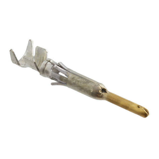
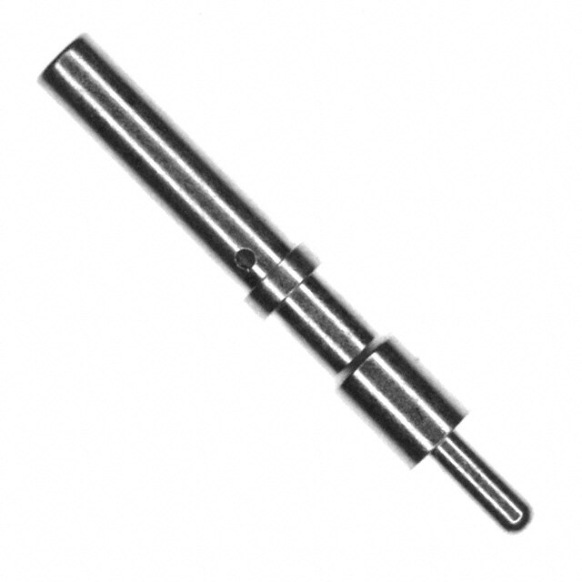
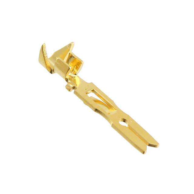
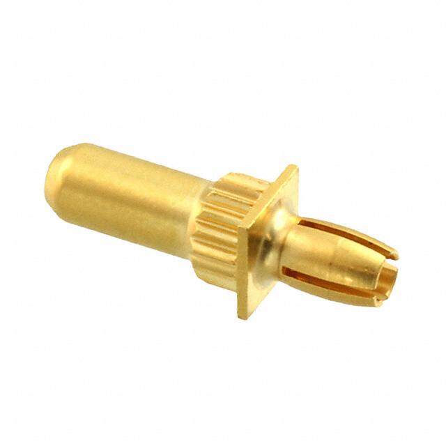
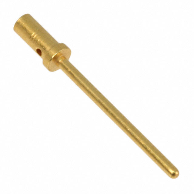
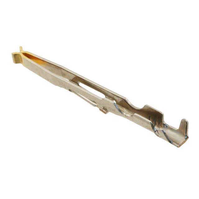
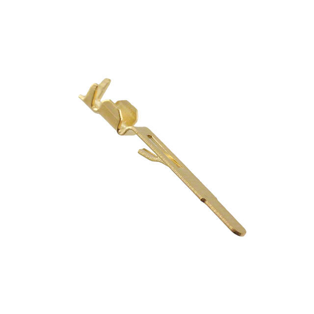
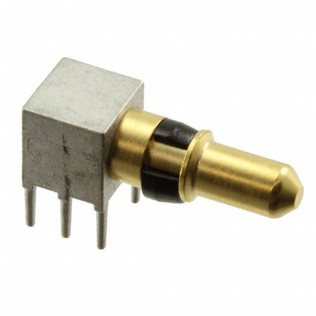
ICGOO电子元器件商城为您提供030-2273-000由ITT CANNON设计生产,在icgoo商城现货销售,并且可以通过原厂、代理商等渠道进行代购。 030-2273-000价格参考。ITT CANNON030-2273-000封装/规格:背板连接器 - 触头, Contact Gold Signal Pin 20-22 AWG Crimp。您可以下载030-2273-000参考资料、Datasheet数据手册功能说明书,资料中有030-2273-000 详细功能的应用电路图电压和使用方法及教程。
ITT Cannon, LLC的030-2273-000是一款背板连接器触头,常用于高可靠性电子系统中。该触头设计用于配合背板连接器使用,确保电路板之间稳定、可靠的电气连接。

其主要应用场景包括:

1. 通信设备:广泛应用于电信交换系统、数据通信设备和网络基础设施中,用于实现高速、稳定的信号传输。

2. 工业控制系统:在自动化控制系统、工业计算机和PLC(可编程逻辑控制器)中,用于连接主背板与各功能模块,保障设备稳定运行。

3. 航空航天与国防:因其高可靠性和耐用性,适用于军用通信设备、雷达系统和航空电子系统等对连接器性能要求极高的领域。

4. 测试与测量设备:用于高精度测试仪器和测量设备中,确保测试过程中信号传输的准确性和稳定性。

5. 医疗电子设备:在高端医疗成像设备和诊断仪器中,用于模块间的电气连接,支持设备高效、安全运行。

该触头具备良好的导电性和耐插拔性能,适用于需要频繁插拔或长期稳定运行的场合,是高可靠性电子系统中的关键组件。
| 参数 | 数值 |
| 产品目录 | |
| 描述 | RP CON 20 HD LIF PIN CRIMP |
| 产品分类 | |
| 品牌 | ITT Cannon |
| 数据手册 | |
| 产品图片 | |
| 产品型号 | 030-2273-000 |
| rohs | 含铅 / 不符合限制有害物质指令(RoHS)规范要求 |
| 产品系列 | 600 BKA |
| 其它名称 | 302273000 |
| 包装 | 散装 |
| 引脚或插座 | 引脚 |
| 标准包装 | 1 |
| 类型 | 信号 |
| 线规 | 20-22 AWG |
| 触头端接 | 压接 |
| 触头镀层 | 金 |
| 触头镀层厚度 | - |
| 额定电流 | - |

.jpg)
.jpg)

PDF Datasheet 数据手册内容提取
Rack & Panel Connectors Catalog
Amazing things happen When great things connect ITT Cannon is a leading global manufacturer of connector products serving international customers in the aerospace and defense, industrial and medical end markets. Whether delivering critical specs to aircraft pilots, streaming data through communications satellites or enabling ultrasound equipment to give expectant parents a first look at their unborn child, ITT Cannon connects the world’s most important information to the people who need it. More than a Century of Connections About ITT Since 1915, Cannon products have been used ITT is a diversified leading manufacturer of highly in a history of “firsts. ”From the first “talking” engineered critical components and customized movie to the first man on the moon, Cannon has technology solutions for the energy, transportation set the standard for reliable, harsh environment and industrial markets. Building on its heritage of interconnect solutions.” Today we proudly continue innovation, ITT partners with its customers to deliver our legacy of innovation with a goal to connect enduring solutions to the key industries that underpin the world and inspire the successes of the next our modern way of life. Founded in 1920, ITT is century—because amazing things happen when headquartered in White Plains, N.Y., with employees great things connect. in more than 35 countries and sales in a total of approximately 125 countries. Visit ittcannon.com to learn more. For more information visit itt.com 2 www.ittcannon.com
Commercial Aerospace Medical Military & Defense ITT Cannon’s connector portfolio is one of the most extensive in the industry, offering Industrial customers a range of off-the-shelf and customized interconnect solutions for multiple markets and applications. Visit ittcannon.com to learn more. www.ittcannon.com 3
Table of contents ITT Cannon Brand Overview ..............................................................................................................2 Introduction: Rack & Panel Connectors ..............................................................................................5 BKA ARINC 600 .................................................................................................................................6 BKA ARINC 600 with ARINC 801 Inserts ..........................................................................................11 SGA (Single Gang ARINC 600) .........................................................................................................23 DPXMA/ME (ARINC 404) .................................................................................................................29 DPXNA/DPXNE ................................................................................................................................44 BKA & DPX Contacts .......................................................................................................................61 DPK (83733-Style) ..........................................................................................................................79 DPA ...............................................................................................................................................97 DPGM/DPJM/DPJMB .....................................................................................................................102 DPD/DPDMA ................................................................................................................................110 About ITT Cannon .........................................................................................................................122 Product Safety Information ............................................................................................................123 Meet Some of Our Most Popular Connectors .................................................................................124 4 www.ittcannon.com
Introduction: Rack & Panel Connector Solutions Learn more about our world-class manufacturing processes, facilities and RoHS compliance on page 121 Designed for exceptional performance in harsh or visit ittcannon.com environments, ITT Cannon’s Rack & Panel interconnect solutions are manufactured to the highest quality and reliability standards for the aerospace & defense industry. At ITT Cannon, our legacy of innovation and expertise in the design and engineering of Rack & Panel connectors Our tradition of engineering excellence continues with has established industry and competitive benchmarks the BKA Rack & Panel Connector with ARINC 801 ASR. for decades. From our environment-resistant DPK Designed for use in harsh environment applications interconnect, which was designed into nearly every U.S. that require quick and accurate data transfer such as space flight and mission flown during the 1960s, to the In-Flight Entertainment/Connectivity, this innovative groundbreaking expansion of Rack & Panel Connectors with fiber optic interconnect solution supports transmission the introduction of our innovative BKAD/E Series in the speeds of 10 gigabits/sec (Gb/S) or more. Built for 1970s, ITT Cannon has achieved significant milestones. optimum performance in the most extreme conditions, the BKA Rack & Panel Connector with ARINC 801 ASR Today, we are recognized as an industry leader in delivers signals, video and data when it matters most. rectangular Rack & Panel interconnect solutions, offering See page 11 for more details or visit ittcannon.com an unparalleled range of off-the-shelf and custom products to align with customer needs. Our latest is the BKA ARINC 600 Rack & Panel with ARINC 801 ASR, an integral part of our end-to-end ARINC 801 Fiber Optic Series for commercial and military aviation. Now and in the future, we remain committed to manufacturing the most reliable, high performance and cost-effective Rack & Panel connectors available to meet the demands of a dynamic marketplace. Because at ITT Cannon, amazing things happen when great things connect. BKAD/E/F SGA DPX DPXNE/NA DPK DPA ARINC 600 ARINC 600 ARINC 404 AS81659 83733-Style Type Plug and Socket Current see ARINC 600 AS39029 Rating Contact AS39029 Resistance Contact AS39029 Material Shell see ARINC 600 Various AS81659 83733-Style Shell Material Aluminum Alloy Dimensions shown in inches (mm) Specifications and dimensions subject to change www.ittcannon.com 5
BKA (ARINC 600) Product Overview BKA connectors represent the standard for Avionic systems developed to support the Air Transportation market. They are blind mate connectors designed per ARINC 600. These connectors are available in 3 and 6 gang configurations and can accommodate up to 800 low insertion force contacts. The inserts are field replaceable. BKA connectors are available in environmental and non-environmental versions. BKAC BKAD/E BKAF/X Rear Release/Rear Removable Rear Release/Rear Removable Front Release/Front Removable Size 12, 16, 20, 22 Crimp Contacts Size 12, 16, 20, 22 Crimp Contacts Size 22 Solder Tail and Wrap Post Contacts BKAC is a combination of BKAD (no BKAD/E connectors represent the environmental O-ring) with inserts not standard for new avionic systems This new connector is totally potted into the shell. BKAE in which developed to support the air intermateable and intermountable with dielectric inserts have a wire seal in the transportation market. Several ARINC 600 connectors now in the field. grommet on the rear surface. important design concerns have been addressed and solved in this new series. The BKAF permits the user to easily High mating forces of pluggable replace a contact in case of problems, modules in a rack have been reduced rather than disassemble the entire by approximately two-thirds. connector--it is available with size 22 contacts in wrap post or solder-tail The low insertion force contacts are versions. The system maintains the also interchangeable with the contacts advantages of low insertion force used in the DPX series and permit technology incorporated in all retrofit of existing equipment. ARINC 600 connectors. BKAX contacts are front release and front removable • Low insertion force contacts • Up to 800 size 22 contacts in one connector • Both environmental and non- environmental versions • Crimp, coax, power, printed circuit and wire wrapable post style contacts • Polarizing posts that are removable from the mating face • Uses standard DPX crimp, insertion/extraction tooling • Field replaceable inserts for size 22 and power contacts • Waveguide connections available Dimensions shown in inches (mm) Specifications and dimensions subject to change 6 www.ittcannon.com
BKA (ARINC 600) Product Overview (continued) Performance and Material Specifications BKAD BKAE/C BKAF/X Specifications Material Aluminum alloy QQ A-591/A380 Shell & Waveguide Finish Alodine 1200 MIL-C-5541 Insulator Material Thermoset N/A Material Copper alloy QQ-C-533 Contacts Finish Gold over Nickel MIL-G-45204 Termination Crimp P.C./Wrap Post Grommets & Seals Material N/A Silicone-based N/A N/A Elastomer O-Ring Material Electrical Data Max. Current for Tests Insulation O.D. Max. Potential Drop Contact Size Wire Size (Amps) per AS39029 and Limits (Inch) Max. (Millivolts) at 25°C ARINC 600 12 23.0 60 12 .135 (3.43) 14 17.0 60 16 13.0 65 16 .103 (2.62) 20 7.5 55 20 7.5 65 20 22 .071 (1.80) 5.0 55 24 3.0 45 22 5.0 55 22 24 .054 (1.37) 3.0 45 26 2.0 40 Dimensions shown in inches (mm) Specifications and dimensions subject to change www.ittcannon.com 7
BKA (ARINC 600) How to Order Product BKA (Per ARINC 600) BKA R D 2 - A234 M - 3 00 01* - F0 RoHS Version: RoHS Compliant R - (Optional) Finish: Trivalent Chromate Class: C - Same as E, except uses BKAD shells and Less O-rings on plug side D - Non-Environmental (rear release, crimp contacts) E - Environmental (rear release, crimp contacts) Receptacle only - Non-environmental (front release, solder and F - wrap post #22 contact, all others are rear release) Plug only - Non-environmental (front release, solder and PF - wrap post #22 contact, all others are rear release) Non-environmental connector using filtered contacts. See ITT Filter T - Connector catalog for further details. (Reference only) X - Receptacle only - All contacts are front release, for PCB Applications only PX - Plug only - All contacts are front release, for PCB Applications only ARINC 600 Original Mating Forces Shell Size: 1 - Max. contact capacity - 125 27 lbs * 2 - Max. contact capacity - 400 60 lbs * 3 - Max. contact capacity - 800 105 lbs * Connector Layout See Pages 12-16 for Connector Layouts Description: Size 1 Coax Connector contains modified 71W1 or 2W2 insert (four Mounting Insert Modifier: M - screw hole locations and coaxial contact used in this insert are interchangeable between other manufacturers Shell Style: 3 - Plug (Rack side) 4 - Receptacle (Box side) Connector See Page 9 for Connector Mounting Modifiers Mounting Modifier: Polarizing Position: See Polarization chart on Page 22 for Position 01 01 - through 216 (per ARINC 600) 00 for polarization indicates that polarizing hardware is not supplied (i.e., BKAD2-313-30000) 00 - Blank or no position indicated means - Polarizing posts or keys not installed but supplied with connector (i.e., BKAD2-313-300) Modifier (Contact, F0 - See Page 10 for Modifiers (Contact, Finish, Material) Finish, Material): ANY OTHER COMBINATION OF INSERTS WITHIN A SPECIFIC SHELL IS AVAILABLE UPON REQUEST: For additional layouts, consult your account representative. Dimensions shown in inches (mm) Specifications and dimensions subject to change 8 www.ittcannon.com
BKA (ARINC 600) How to Order (continued) Connector Mounting Modifier PLUG AND RECEPTACLE CONNECTORS .148 dia. connector PLUG AND RECEPTACLE CONNECTORS 00 - 47 - mounting holes. This is a Standard Configuration. Surtec 650V Plating-With #4 (.112) - 40 ESNA clinch nuts PLUG AND RECEPTACLE CONNECTORS PLUG AND RECEPTACLE CONNECTORS 01 - With #6 (.138) - 32 ESNA clinch nuts (See Table for quantities) 48 - Electroless Nickel plated shells with 4-40 clinch nuts in all connector mounting holes (See Table for quantities) SIZE 1 RECEPTACLE CONNECTORS ONLY 02 - Standard Configuration with three PWB mounting lugs machined off. PLUG CONNECTORS ONLY-SIZE 1 ONLY 50 - Standard Configuration with .0008-.0012 thick nickel plated PLUG AND RECEPTACLE CONNECTORS die cast shell and EMI springs. 03 - With #4 (.112) - 40 ESNA clinch nuts (See Table for quantities) PLUG CONNECTORS ONLY-SIZE 1 ONLY SIZE 1 RECEPTACLE CONNECTORS ONLY 51 - Standard Configuration with .0008-.0012 thick nickel plated die With four #6 (.138) - 32 ESNA clinch nuts. Modified shell - three cast shell and EMI springs and all holes with #6-32 clinch nuts 04 - PWB mounting lugs machined off and O/A length of flange shortened to 6.980. (See Table for quantities) PLUG CONNECTORS ONLY-SIZE 2 AND 3 ONLY 52 - Standard Configuration with .0008-.0012 thick nickel plated die SIZE1 PLUG CONNECTOR ONLY cast shell and EMI springs and #6-32 clinch nuts in all places. 06 - With #6 (.138) - 32 ESNA clinch nuts (See Table for quantities) and with side mounting lugs machined off. (See Table for quantities) PLUG CONNECTORS ONLY-SIZE 2 AND 3 ONLY 53 - Standard Configuration with .0008-.0012 thick nickel plated die cast SIZE 2 AND 3 PLUG AND RECEPTACLE CONNECTORS ONLY shell and EMI springs and #6-32 clinch nuts except in center holes. 08 - With #4 (.112) - 40 ESNA clinch nuts in all connector mounting holes (See Table for quantities) PLUG CONNECTORS ONLY-SIZE 2 AND 3 ONLY 54 - Standard Configuration with .0008-.0012 thick nickel plated die SIZE 2 AND 3 PLUG AND RECEPTACLE CONNECTORS ONLY cast shell and EMI springs with #6-32 clinch nuts (4 places). 09 - With #6 (.138) - 32 ESNA clinch nuts in all connector mounting holes (See Table for quantities) PLUG CONNECTORS ONLY-SIZE 2 AND 3 ONLY 55 - Standard Configuration with .0008-.0012 thick nickel plated die cast PLUG CONNECTORS ONLY shell and EMI springs and all holes with #6-32 clinch nuts (6 places). Standard Configuration with .0008-.0012 thick nickel plated shell. 22 - The shell is provided with an EMI/Grounding spring. Metallic inserts, PLUG CONNECTORS ONLY-SIZE 2 AND 3 ONLY if supplied, are selectively plated - I.D. Silver; O.D. Nickel over Silver. 56 - Standard Configuration with .0008-.0012 thick nickel plated die The contact retaining/grounding clips are gold plated. cast shell and EMI springs and #4-40 clinch nuts in all places. PLUG AND RECEPTACLE CONNECTORS PLUG CONNECTORS ONLY-SIZE 2 AND 3 ONLY 23 - With floating eyelets (.048 min. radial float) in four corner connector Standard Configuration with .0008-.0012 thick nickel plated die mounting holes. 57 - cast shell and EMI springs and #6-32 clinch nuts (8 places no center hole clinch nuts). RECEPTACLE CONNECTORS ONLY 25 - 01 mod with #6 (.138) - 32 ESNA clinch nuts and .0008-.0012 thick PLUG CONNECTORS ONLY-SIZE 1 ONLY nickel plated shell. (See Table for quantities) Standard Configuration with .0008-.0012 thick nickel plated die 58 - cast shell and EMI springs. With floating eyelets (.048 min. radial 37 - PLUG CONNECTORS ONLY float) in four corner connector mounting holes. With metric clinch nuts M3 X 6 (See Table for quantities) PLUG CONNECTORS ONLY Quantity of Clinch Nuts With metric clinch nuts M3 X 6 (See Table for quantities) and with Mounting .0008-.0012 thick nickel plated shell. The shell is provided with an Shell Size Plug Receptacle 38 - Modifier EMI/ Grounding spring. Metallic inserts, if supplied, are selectively Connector Connector plated - I.D. Silver; O.D. Nickel over Silver. The contact retaining/ grounding clips are gold plated. 01, 03, 04, 1 4 4 06, 25, 37, 2 4 6 PLUG CONNECTORS ONLY 38, 47, 50 45 - Standard Configuration with .0008-.0012 thick nickel plated die 3 8 10 cast shell. The shell is provided without an EMI/Grounding spring. 1 4 4 PLUG AND RECEPTACLE CONNECTORS 08, 09, 48 2 10 10 46 - .148 dia. connector mounting holes. SURTEC 650V ROHS 3 12 14 Compliant plating. Dimensions shown in inches (mm) Specifications and dimensions subject to change www.ittcannon.com 9
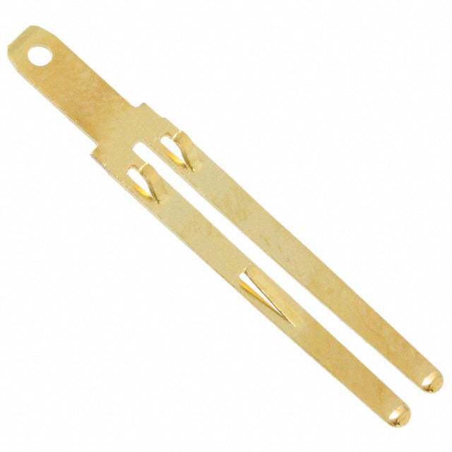
BKA (ARINC 600) How to Order (continued) Modifier (Contact, Finish, Material) BKAC/BKAD/BKAE/BKAF/BKAX Rear release, crimp, signal and power contacts supplied with BLANK - connector (when applicable) Contacts not supplied with connector F0 - (F0 not stamped on connector) Less contacts and waveguide F00 - (F00 not stamped on connector) BKAF - Signal contacts (size 22) are front release, front removable with solder post termination. Power contacts are rear release, rear removable with crimp termination. Stamped Contacts - Receptacle Side Only Front release solder PCB contacts installed .150 (3.81). Stamped PCB contacts installed .150 (3.81). SE - STE* - (Coax, Triax, and Quadrax does not have contacts installed) (Coax, Triax, and Quadrax does not have contacts installed) Front release solder PCB contacts installed .250 (6.35). Stamped PCB contacts installed .250 (6.35). SF - STF - (Coax, Triax, and Quadrax does not have contacts installed) (Coax, Triax, and Quadrax does not have contacts installed) Front release solder PCB contacts installed .375 (9.53). Stamped PCB contacts installed .375 (9.53). SG - STG - (Coax, Triax, and Quadrax does not have contacts installed) (Coax, Triax, and Quadrax does not have contacts installed) Front release solder PCB contacts installed .500 (12.7). Stamped PCB contacts installed .500 (12.7). SH - STH* - (Coax, Triax, and Quadrax does not have contacts installed) (Coax, Triax, and Quadrax does not have contacts installed) Front release .025(0.63) Sq. x .250 (6.35) (1 wrap) wrap post WA - and crimp, rear release power contacts (when applicable) supplied with connector Front release .025(0.63 Sq. x .375 (9.53) (2 wraps) wrap post WB - and crimp, rear release power contacts (when applicable) supplied with connector BKAX - Signal contacts (size 22) are front release, front removable with solder post termination. Power contacts are front release, front removable with solder post termination. Stamped Contacts - Receptacle Side Only Front release solder PCB contacts installed .150 (3.81) including Stamped PCB contacts installed .150 (3.81) including Coax, SS- STS* - Coax, Triax, and Quadrax. All contacts to be PCB. Triax, and Quadrax. All contacts to be PCB. Front release solder PCB contacts installed .250 (6.35) including Stamped PCB contacts installed .250 (6.35) including Coax, ST - STT - Coax, Triax, and Quadrax. All contacts to be PCB. Triax, and Quadrax. All contacts to be PCB. Front release solder PCB contacts installed .375 (9.53) including Stamped PCB contacts installed .375 (9.53) including Coax, SU - STU - Coax, Triax, and Quadrax. All contacts to be PCB. Triax, and Quadrax. All contacts to be PCB. Front release solder PCB contacts installed .500 (12.7) including Stamped PCB contacts installed .500 (12.7) including Coax, SV - STV* - Coax, Triax, and Quadrax. All contacts to be PCB. Triax, and Quadrax. All contacts to be PCB. Front release solder PCB contacts installed .150 (3.81) including Stamped PCB contacts installed .150 (3.81) including Quadrax. SW - STW* - Quadrax. (Coax and Triax does not have contacts installed) (Coax and Triax does not have contacts installed) Front release solder PCB contacts installed .250 (6.35) including Stamped PCB contacts installed .250 (6.35) including Quadrax. SX - STX - Quadrax. (Coax and Triax does not have contacts installed) (Coax and Triax does not have contacts installed) Front release solder PCB contacts installed .375 (9.53) including Stamped PCB contacts installed .375 (9.53) including Quadrax. SY - STY - Quadrax. (Coax and Triax does not have contacts installed) (Coax and Triax does not have contacts installed) Front release solder PCB contacts installed .500 (12.7) including Stamped PCB contacts installed .500 (12.7) including Quadrax. SX - STZ* - Quadrax. (Coax and Triax does not have contacts installed) (Coax and Triax does not have contacts installed) NOTE: Coaxial contacts to be ordered separately. All Fiber Optic layouts will not have Fiber Optic contacts installed * STE, STH, STS, STV, STW, STZ (Tooling will need to be assessed for these versions) Dimensions shown in inches (mm) Specifications and dimensions subject to change 10 www.ittcannon.com
BKA (ARINC 600) Contact Arrangements Fiber Optic Contact Arrangements Introducing the New ARINC 801 Inserts for BKA (ARINC 600) Connectors Designed for use in applications that require quick and accurate data transfer, Cannon’s ARINC 801 Fiber Optic Interconnect Solutions are capable of operating at transmission speeds of 10 gigabits/sec (Gb/S) or more. Built for optimum performance in extreme conditions, our ARINC 801 Fiber Optic Series delivers signal, video and data when it matters most. Several standard ARINC 600 insert arrangements are available for Cannon’s Rack & Panel connector family. 12F12 17Q2 12F5C2 20F12Q8 F36 20F12T8 Insert Description Shell Size Shell Style Cavity 12F12 12 #16 Fiber Optic 1 C 12 #16 Fiber Optic 17Q2 3 #16 2 #8 (Quadrax) C or F 5 #16 Fiber Optic 4 #12 BKAC/BKAD/BKAE/BKAF 12F5C2 1 #16 2/3 2 #5 (Coax) 20F12Q8 12 #16 Fiber Optic 20F12T8 8 #8 (Quadrax or Twinax) A,B,D,E F36 36 #16 Fiber Optic Dimensions shown in inches (mm) Specifications and dimensions subject to change www.ittcannon.com 11
BKA (ARINC 600) Contact Arrangements (continued) Shell Size 1 - BKAC/BKAD/BKAE/BKAF/BKAX Cavity A or B Contact Arrangements (Plug rear face shown) 1 2 2 BKAC/BKAD/BKAE 2 3 3 3 4 4 Rear surface white on blue to indicate 45 56 56 rear release rear removal contacts 67 78 78 BKAF/BKAX (Front Release) 1T 9 9 Engaging end surface white on red to 10 10 11 11 indicate front release front removal 2T 12 12 contacts 13 13 14 14 15 15 30T2 / 30Q2 60 Blank 28 #22 2 # 8 Twinax/Coax/Quadrax 60 #22 No Contacts (#8 Grounded to Shell) Shell Size 1 - BKAC/BKAD/BKAE/BKAF/BKAX Shell Cavity C Contact Arrangements (Plug rear face shown) 1 5 1 1 9 1 BKAC/BKAD/BKAE 2 3 2 234 10 6 2 Rreeaarr rseulrefaascee r weahrit er eomn obvlaule c toon itnadcitcsa te 4 5 11 3 BKAF/BKAX (Front Release) 3 6 7 7 12 4 Engaging end surface white on red to 8 4 5 9 8 indicate front release front removal 10 contacts 4 / 4T4 5W2 40 12F12 Blank A4W4 1 #12 12 #16 4 #12 2 #16 40 #22 No Contacts Fiber Optic 2 #5 Coax Shell Size 2/3 - BKAC/BKAD/BKAE/BKAF/BKAX Shell Cavity A,B,D,E Contact Arrangements (Plug rear face shown) AA CC BB DD FF EE GG JJ HH KK LL 2W2 / 2G2 4W4 10T10 / 10P10 11Q11 24 4 Modified 10 #8 Triax/Coax 2 #1 Coax #1 Coax (#8 Grounded to Shell) 11 #8 Quadrax 24 #12 (Metallic Insert) (Metallic Insert) For Contacts Cavity Location and Contact Cavity Identification reder to ARINC 600 or Consult Your Account Representative. Dimensions shown in inches (mm) Specifications and dimensions subject to change 12 www.ittcannon.com
BKA (ARINC 600) Contact Arrangements (continued) Shell Size 2/3 - BKAC/BKAD/BKAE/BKAF/BKAX Shell Cavity A,B,D,E Contact Arrangements (Plug rear face shown) 1 2 3 4 5 8 6 7 9 10 11 12 13 14 15 16 17 20 18 19 21 22 23 24 25 26 27 28 29 32 30 31 33 34 35 36 20F12Q8 / 20F12T8 F36 49T2 60 71W1 / 71W1A 12 #16 Fiber Optic 47 #20 70 #22 36 #16 Fiber Optic 60 #20 8 #8 Quadrax 2 #8 Triax 1 #1 Coax 71W1B 110 150 120T2 / 120Q2 121 100 #22 118 #22 110 #22 70 #22 5 #12 150 #22 2 #8 Twinax/Coax/Quadrax 5 #16 1 #1 Coax 5 #20 (#8 Grounded to Shell) 6 #20 BKAC/BKAD/BKAE Rear surface white on blue to indicate rear release rear removal contacts for inserts containing standard signal & power contacts BKAF/BKAX (Front Release) Engaging end surface white on red to indicate front release front removal contacts for inserts containing standard signal & power contacts Blank No Contacts Shell Size 2/3 - BKAC/BKAD/BKAE/BKAF/BKAX Shell Cavity C or F Contact Arrangements (Plug rear face shown) 1 2 1 4 3 2 1 1 5 6 2 3 2 3 6 5 7 8 8 7 45 4 10 9 1951 240 11 6 5 6 21 22 13 12 23 24 3 4 6 6T6 / 6Q6 / 6QA6 / 6P6 10C5T2 13W2 / 13Q2 / 13WQ2 24T4 / 24Q4 1 #20 4 #20 6 #8 Triax/Quadrax 2 #20 Insulated 4 #12 20 #20 6 #8 (Metallic Insert) 2 #8 Triax 3 #16 4 #8 Triax/Quadrax 5 #5 Coax 2 #5 Coax/ #8 Quadrax For Contacts Cavity Location and Contact Cavity Identification refer to ARINC 600 or Consult Your Account Representative. Dimensions shown in inches (mm) Specifications and dimensions subject to change www.ittcannon.com 13
BKA (ARINC 600) Contact Arrangements (continued) Shell Size 2/3 - BKAC/BKAD/BKAE/BKAF/BKAX Shell Cavity C or F Contact Arrangements (Plug rear face shown) 1 2 3 4 5 1 6 A B C D E F G H J K 7 12 1 6 7 8 9 10 2 13 18 3 11 12 13 14 15 19 24 4 5 16 17 18 19 20 25 29 51 52 53 54 55 21 22 23 24 25 30 34 56 57 58 59 25 34 59 64Q2 70Q2 50 #22 60 #22 24 #20HD 68 #22 25 #16 5 #16 2 #16 10 #16 2 #8 Quadrax 4 #12 2 #8 Quadrax B C D E F G H J K B C D E F G H J K 2 2 1 1 3 3 2 2 4 4 3 3 5 5 4 4 6 6 5 5 7 7 6 6 8 8 7 7 B CD EF GH JK 8 8 9 9 1 2 3 4 5 10 B C D E F G H J K 10 84 85 100 12F5C2 17Q2 1 #16 80 #22 3 #16 80 #22 4 #12 4 #20 100 #22 2 #8 Quadrax 4 #20 2 #5 Coax 1 #16 12 #16 Fiber Optic 5 #16 Fiber Optic BKAC/BKAD/BKAE BKAF/BKAX (Front Release) Rear surface white on blue to indicate rear Engaging end surface white on red to indicate front release rear removal contacts for inserts release, front removal contacts for inserts containing standard signal & power contacts containing standard signal & power contacts NOTE: In layouts using #22 contacts mixed with NOTE #22 Contacts are Socket contacts, 20HD,16, any other contact size (20HD, 16, 12), the size 12 are Pin contacts. #22 contact type (pin or socket) determines the insulator as a pin insert or a socket insert. Blank No Contacts For Contacts Cavity Location and Contact Cavity Identification refer to ARINC 600 or Consult your account representative. Shell Size 2/3 BKAC/BKAD/BKAE Shell Cavity A,B,D,E Contact Arrangements – PHD Fiber Optic ARINC 600 PHD-2 PHD-4 PHD-8 PHD-16 PHD-24 PHD-32 All arrangements utilize PHD-T16-**** size 16 fiber optic termini. Please consult your account representative for higher density (72 and 88 cavity) layouts utilizing PHD-T22-**** size 22 fiber optic termini All layouts shown are Receptacle engaging face and rear release. Dimensions shown in inches (mm) Specifications and dimensions subject to change 14 www.ittcannon.com
BKA (ARINC 600) Shell Cavity Identification CONNECTOR LAYOUT DESCRIPTION Note: All layouts with “OPEN” insert cavity are not supplied with an insulator. If a blank insert is required, please consult your account representative; all standard blank inserts are plastic. Three digit number contained within the shell layout indicates total number of contacts available (including Waveguide). Insert Designator Number - Shell Size 1 ITT Cannon Cavity A Cavity B Cavity C ITT Cannon Cavity A Cavity B Cavity C 5 OPEN OPEN 5W2 A094 30T2 60 4 35 30T2 BLANK 5W2 95 60 30T2 5W2 60 OPEN 60 OPEN A095 30T2 60 5W2 A060 60 OPEN OPEN A100 60 BLANK 40 64 30T2 30T2 4 120 60 60 OPEN 65 OPEN 60 5W2 124 60 60 4 A065 60 OPEN 5W2 125 60 60 5W2 B065 30T2 30T2 5W2 130 60 30T2 40 C065 BLANK 60 5W2 A130 30T2 60 40 94 60 30T2 4 160 60 60 40 Insert Designator Number - Shell Size 2 ITT Cannon Cavity A Cavity B Cavity C ITT Cannon Cavity A Cavity B Cavity C 13 OPEN OPEN 13W2 B121 121 OPEN OPEN 017M 2W2 2W2 13W2 122 49T2 49T2 24T2 019M 4W4 2W2 13W2 124 BLANK 24 100 Q34 11Q11 10T10 13Q2 133 60 60 13W2 Q035 11Q11 11Q11 13Q2 A133 24 24 85 59 BLANK BLANK 59 Q135 11Q11 24 100 66 BLANK 60 6 137 121 10T10 6T6 Q69 11Q11 24 34 142 71W1 71W1 OPEN 71 OPEN 71W1 OPEN 143 120T2 10T10 13W2 A071 71W1 OPEN OPEN Q144 120T2 11Q11 13W2 Q074 4W4 11Q11 59 Q154 120T2 11Q11 13W2 Q075 11Q11 BLANK 64Q2 155 71W1 71W1 13W2 Q81 11Q11 11Q11 59 155M 71W1A 71W1A 13W2 084M BLANK 71W1A 13W2 V155M 71W1B 71W1A 13W2 085M WAVEGUIDE 71W1 13W2 158M 2W2 71W1A 85 A085M 71W1 WAVEGUIDE 13W2 A158M 2W2 71W1B 85 B085 OPEN OPEN 85 163 OPEN 150 13W2 086M 2W2 71W1A 13W2 A163 150 OPEN 13W2 Q086 11Q11 11Q11 64Q2 QB163 OPEN 150 13Q2 Q089 4W4 BLANK 85 164 150 WAVEGUIDE 13W2 93 4W4 4W4 85 A164 WAVEGUIDE 150 13W2 Q096 BLANK 11Q11 85 A165M 2W2 150 13W2 100 OPEN OPEN 100 167 4W4 150 13W2 A100 BLANK OPEN 100 173M 2W2 71W1B 100 Q107 11Q11 11Q11 85 A173 150 10T10 13W2 109 60 49T2 BLANK B173 10T10 150 13W2 120 60 60 METAL BLANK 187 24 150 13W2 121 OPEN 121 OPEN Q225 11Q11 150 64Q2 A121 121 BLANK BLANK A234M 71W1A 150 13W2 OTHER COMBINATION OF INSERTS WITHIN A SPECIFIC SHELL ARE AVAILABLE UPON REQUEST, PLEASE CONSULT YOUR ACCOUNT REPRESENTATIVE. Dimensions shown in inches (mm) Specifications and dimensions subject to change www.ittcannon.com 15
BKA (ARINC 600) Shell Cavity Identification (continued) CONNECTOR LAYOUT DESCRIPTION Note: All layouts with “OPEN” insert cavity are not supplied with an insulator. If a blank insert is required, please consult your account representative; all standard blank inserts are plastic. Three digit number contained within the shell layout indicates total number of contacts available (including Waveguide). Insert Designator Number - Shell Size 2 (continued) ITT Cannon Cavity A Cavity B Cavity C ITT Cannon Cavity A Cavity B Cavity C 235 150 BLANK 85 301 121 121 59 240 60 121 59 306 150 150 6T6 246 120T2 120T2 6T6 313 150 150 13W2 Q246 150 11Q11 85 Q313 150 150 13WQ2 248 121 121 6T6 324 150 150 24T4 250 OPEN 150 100 Q324 150 150 24Q4 A250 150 BLANK 100 327 121 121 8 251 WAVEGUIDE 150 100 330 150 121 59 Q253 120T2 120T2 13WQ2 340 120T2 120T2 100 254 110 110 34 342 121 121 100 A284 121 150 13W2 370 120T2 150 100 300 150 150 OPEN 400 150 150 100 Insert Designator Number - Shell Size 3 ITT Cannon Cavity A Cavity B Cavity C Cavity D Cavity E Cavity F 21 4W4 4W4 13W2 BLANK OPEN OPEN 26 OPEN OPEN 13W2 OPEN OPEN 13W2 113 OPEN OPEN 100 OPEN OPEN 13W2 A113 OPEN OPEN 13W2 OPEN OPEN 100 114 4W4 4W4 13W2 4W4 4W4 85 Q198 11Q11 11Q11 13Q2 11Q11 11Q11 13Q2 Q209 11Q11 11Q11 BLANK 11Q11 150 13Q2 Q253 150 121 13W2 11Q11 24 34 Q261 4W4 120T2 BLANK 4W4 120T2 13Q2 269M 2W2 2W2 13W2 2W2 150 100 271C 4W4 4W4 13W2 BLANK 150 100 271M 2W2 2W2 13W2 4W4 150 100 Q274 4W4 120T2 13Q2 4W4 120T2 13Q2 284 71W1 71W1 OPEN 71W1 71W1 OPEN Q307 110 11Q11 6Q6 24 150 6Q6 310 71W1 71W1 13W2 71W1 71W1 13W2 Q324 11Q11 METAL BLANK METAL BLANK 150 150 13Q2 326 OPEN 150 13W2 OPEN 150 13W2 330M 2W2 2W2 13W2 150 150 13W2 A330M 150 150 13W2 2W2 2W2 13W2 Q435 11Q11 11Q11 13Q2 150 150 100 Q487 11Q11 150 13Q2 150 150 13Q2 496 121 121 6T6 121 121 6T6 600 150 150 OPEN 150 150 OPEN Q619 150 150 13Q2 150 150 6T6 626 150 150 13W2 150 150 13W2 Q626 150 150 13Q2 150 150 13Q2 713 150 150 100 150 150 13W2 734 150 150 100 150 150 34 800 150 150 100 150 150 100 OTHER COMBINATION OF INSERTS WITHIN A SPECIFIC SHELL ARE AVAILABLE UPON REQUEST, PLEASE CONSULT YOUR ACCOUNT REPRESENTATIVE. Dimensions shown in inches (mm) Specifications and dimensions subject to change 16 www.ittcannon.com
BKA (ARINC 600) Shell Dimensions Plug Dimensions – Shell Size 1 .205(5.21)* 1.B40K2AE(35S.E6R1)IMESAX 11..019100((2287..1699)) .195 (4.95) .130(3.30) .120(3.05) 1.195 (30.35)MAX .655 (16.64) .385 (9.78) MAX .645 (16.38) BKADSERIES .148 +_.003(3.76+_0.08)DIA 1.150(29.21)MIN 1.102(27.99) MAX 4 PLCS MTG HOLES .653 (16.59) .647 (16.43) .55..445655 ((113388..5861)) .1.12055 ((32.1.687))* A ..118606 ((44..5272))D A 4 PL 6.995 MAX (177.67) 33..882155 ((9976..1960)) .1.13155 ((32..4932))* B B 66..335455 ((116611..4126)) (167M.85I9.N001) ..1023004(RR. 7P6MLM)AAXX (3.05) 6.(510605 .M10A)X 66..664259 ((116688..7388)) (166.315.337) 4 PL .6(.156155. 4M8I)N 22..005499 ((5522..3004)) (166.314.271) 1.313 (33.35) 1.303(33.10) C .030(.76)R .620MIN .479 (12.17) C MAX4 PL .608MAX (15.75) .469(11.91) .250 (15.44) (6.35) MAX .135 (3.43) .830(21.08) .125 (3.18) .188 (4.78) .820(20.83) ..557655 ((1144..6305)) 1.1B9K8A (D30S.4E3R)I EMSAX .184 (4.67) 33..8755 ((99..7582)) .191 (4.85) .705(17.91) BKAESERIES 189 (4.80) .695 (17.65) 1.550(39.37) MAX 3 PL Retainer Plate Size 1 Plug Panel Cutout Receptacle Dimensions – Shell Size 1 BKAESERIES 1.531 (38.89) MAX .2.10955( (54.2.915))* 1B.K22A1D (/3B1K.0A1F) SMEARXIES 1.010(25.65) .130(3.30) .990(25.15) .240(6.10)MAX .191 (4.85) 2PL .120(3.05) .655 (16.64) .189 (4.80) .125 (3.18)* .645 (16.38) .105(2.67) .148 +_.003(3.76+_0.08)DIA .030R 4 PLCS MTG HOLES (.76) MAX 2 PL 5.465(138.81) A A 5.455 (138.56) 7.455 MAX .1.13155 ((32..4932))* B (189.36) 66..335455 ((116611..4126)) (167.847.500) 3.825 (97.16) MIN 3.815 (96.90) 6.627 (168.33) 6.353 6.607(167.82) (161.37) 6.347 2.059 (52.30) B (161.21) 2.049 (52.04) .287 R (7.29) MAX 4 PL 11..331033 ((3333..3150)) C (.62.4100) .120R(3.05) MAX MAX 4 PL C .180(4.57) .166 (4.22)D 4 PL .810(20.57) ..113255 ((33..4138)) B1K.A31D7/B (K33A.F4 5S) EMRAIEXS ..118884 ((44..7687)) 33..6555 ((99..2072)) (1.665.539) .800 (20.32) .575 (14.60) BKAESERIES .647 .565(14.35) 1.670(42.42) .930(23.62) MIN (16.43) .705(17.91) .695 (17.65) Retainer Plate Size 1 Receptacle Panel Cutout For further information, refer to ARINC 600 specification or consult your account representative. *This dimension indicates distance from centerline of retaining screw to the centerline of first contact cavity. Dimensions shown in inches (mm) Specifications and dimensions subject to change www.ittcannon.com 17
BKA (ARINC 600) Shell Dimensions – (continued) Plug Dimensions – Shell Size 2 1.810 (45.97) 1.790 (45.47) 1.431 (36.35) BKAE SERIES 1.421 (36.09) 1.402 (35.61) MAX .655 (16.64) .130 (3.30) 1.195 MAX .645 (16.38) .120 (3.05) (30.35) BKAD SERIES .148 +_003 (3.76 +_0.08) DIA 226500 ((66 6305))* 1.102 (27.99) MAX 10 PLCS MTG HOLES 191 (4.85) 665437 ((1166..5493))030 (.76) R .070 (1.78)* 189 (4.80) MAX 4 PL .050 (1.27) 3 PL A 5.355 (136.02) A 030 R 5.345 (135.76) (.76) 6.360 (161.54) M4 APXL 6.340 (161.04) B 3770 (95.76) 111355 ((23..9423))* B 6(919757 .M67A)X 6.(510605 .M10A)X 6.645 (168.78) (1666..3135.43377) 6(.156155. 4M8I)N 3760 (95.50) 6.629 (168.38) 161.21 6.890 1(32.00 5R) (17M5I.N01) 2004 (50.90) MAX 1994 (50.65) 4 PL 11225488 ((3311..9750)) C .6(1250. 7M5I)N 22..113255 ((5543..2938)) C ((.4411..68526072))D .6(0185 .M44A)X 8 PL 168 (4.27) 1.429 ..886555 ((2211..9772)) 11441105558 (((33455.0..96149))) B1B11.KK15AA958DE0 (S(S33EE09.RR.43II37EE)) SS MMAAXX 118884((44..7687)) ((9933..87755582)) 1.(8((4313566.60.49.. 321M9034)I))N 25(60. 3M5A)X Retainer Plate Size 2 Plug Panel Cutout Receptacle Dimensions – Shell Size 2 B1.K5A31E (S3E8.R8I9E)S MAX 11..871900 ((4455..9477)) 1.431 (36.35) B1.K2A21D /(B3K1.A0F1 )SMEARXIES 1.421 (36.09) 1.530 .655 (16.64) (38.86) 130 (3.30 .645 (16.38) 191 (4.85) MIN .120 (3.05) 189 (4.80) 260 (6.60)* .148 .003 (3.76 +_0.08) DIA. 2 PL 250 (6.35) 10 PLCS MTG HOLES .070 (1.78)* .050 (1.27) 240 (6.10) 030 R MAX (76) A MAX 5.335 (136.02) A 6.353 2 PL 5.345 (135.76) .135 (3.43)* B 6.(917757 .M16A)X B 66..336400 ((116611..5044 (167M.84I7.N500) ((11666.131.4.32771)) ((1313.6.644..23219034)) 1((.4.4011...2 8562P60762L0))D .115 (2.92) 3 PL (6.60) 3.770 (95.76) .230 3.760 (95.50) (5.84) 6.627 (168.33) 2 PL 6.607 (167.82) 21..090944 ((5500..9605)) C 2.133 .(132.005 R) 11..225488 ((3311..9750)) C 22..113255 ((5543..2938)) (27M.07A.86X01) (25.52.0808) ((5254.41..120873)) M4 APXL MIN .287 R (7.29) MAX 8 PL BKAD/BKAF SERIES .653 (16.59) .865 (21.97) ..116588 ((44..2071)) BKA1E.3 S17E R(3IE3.S45) ..118884 ((44..7687)) .365 (9.27).24(60. 1M0A)X .6472 (P16L.C43) .855 (21.72) 1.415 (35.94) 1.670 (42.42) .355 (9.02) 1.405 (35.69) Retainer Plate Size 2 Receptacle Panel Cutout *This dimension indicates distance from centerline of retaining screw to the centerline of first contact cavity. For further information, refer to ARINC 600 specification or consult factory. Dimensions shown in inches (mm) Specifications and dimensions subject to change 18 www.ittcannon.com
BKA (ARINC 600) Shell Dimensions – (continued) Plug Dimensions – Shell Size 3 3.275 (83.18) 3.245 (82.42) BKAE SERIES 1.402 (35.61) MAX 2.891 (73.43) 2.881 (73.18) 1.1(2590. 2M1A)X 11..995455 ((4499..6460)) ..226500 ((66..6305))* ..113200 ((33..5005)) 1.1B0K2A (D2 7S.9E9R)I EMSAX ..665455 ((1166..6348)) .(134.786 + _+_.000.038 D)IA. (14.99.5631) 3.(38140.0 M7)IN .030 (.76)R .070 (1.78)* 14 PLCS MTG HOLES (14.99.4475) MAX 4 PL .060 (1.52) 5.355 (136.02) 5.345 (135.76) .030 R MAX (.76) 4 PL 6.355 (161.42) 6.353 .135 (3.43)* 6.345 (161.16) (161.37) .120 R MAX .115 (2.92) (16M6.55A0.X100) 6.645 (168.78) (166.314.271) (43 .P065L.5)15 MIN 6.629 (168.38) (165.48) 6.995 MAX (177.67) .590 MAX 2.004 (50.90) (14.99) 1.994 (50.65) .385 11..225488 ((3311..9750)) 6(2105 .M75IN) 22..113255 ((5543..2938)) ((9..39.775852)) 33..777600 ((9955..7560)) (4...11586706) D .250 ..889700 ((2222..6110)) 1.1.6588 ((44..2071)) 11..225422 ((3311..8505)) 1.1B9K8A (D30 S.4E3R) IMESAX. ..118884 ((44..7687)) 1(42. 2P2L)(1..(M66665.4.A53379X5)) (.7223..88.388839) ..1198193 (( 44P..88L50)) 1.440 (36.58) BKAE SERIES (16.43) (73.23) 1.430 (36.32) 1.550 (39.37) MAX 2.712 (68.88) 2.702 (68.63) 2.875 (73.02) 2.865 (72.77) Retainer Plate Size 3 Plug Panel Cutout Receptacle Dimensions – Shell Size 3 3.275 (83.18) 3.245 (82.42) 2.891 (73.43) BKAE SERIES 2.881 (73.18) 1.531 (38.89) MAX 1.955 (49.66 BKAD/BKAF SERIES 1.945 (49.40) 1.221 (31.01)MAX 3.000 (76.20) MIN ..226500 ((66..6305))* ..113200 ((33..3005)) ..665455 ((1166..6348)) .(11344. 78P6 L+ _+C_.0S00 .M038 TD)GIA H.OLES ..1198319 ((P44L..8850)) 22..888893 ((7733..3283)) 3 PL .(278.279 R) 8M PALX .240 MAX 5.355 (136.02) .070 (1.78)* (6.10) 5.345 (135.76) .060 (1.52) .030 R MAX (.76) 6.355 (161.42) 2 PL 6.870 6.345 (161.16) .120 R MAX (174.50) (3.05) .960 MIN 4 PL (24.38) .135 (3.43)* .930 .115 (2.92) 66..662077 ((116687..3832)) ..118606 ((44..5272)) D (223 P.6L2) 6.975 MAX 14 PL (177.16) 2.004 (50.90) 1.994 (5011...622554)88 ((3311..9750)) 22..113255 ((5543..2938)) (27M.07A.86X01()25.41.3138)(52M5.2.I8N08) 2.127 3.770 (95.76) (54.03) 3.760 (95.50) .188 (4.78) ..887500 ((2221..1509)) 1.1.6588 ((44..2071)) 11..225422 ((3311..8505)) 1.B6BK17K.0A3A D1(E47/ B2S (.K3E4A32R. F4I)EM 5SS)AEMXRAIXES .184 (4.67) ((.9.933..62505752)) (M.62.A41X00.) (49.116..199)45 273 PL (16(.15..66694.5)4 7323 )PL 1.440 (36.58) (49.45) 1.430 (36.32) 2.712 (68.88) 2.702 (68.63) 2.875(73.02) 2.865(72.77) Retainer Plate Size 3 Receptacle Panel Cutout *This dimension indicates distance from centerline of retaining screw to the centerline of first contact cavity. For further information, refer to ARINC 600 specification or consult factory. Dimensions shown in inches (mm) Specifications and dimensions subject to change www.ittcannon.com 19
BKA (ARINC 600) Shell Dimensions (continued) ARINC 600 Connector Engaging Sequence Mating Flange Flange Spacing PLUG RECEPTACLE Sequence Position With: in. (mm) 1.245 (31.62) 1 No Engagement Nom. Shells Initially 1.110 (28.19) 2 Engaged 1.073 (27.25) Polarizing Pins 1.073 (27.25) 3 #22 Entering Keys 1.023 (25.88) .800 (22.32) #22 .748 (18.99) .805 (20.44) #20 .741 (18.82) Contacts Entering 1.012 (25.70) #22 4 Mating Insulator #16 .949 (24.10) SIZE 1 ONLY #12 1.008 (23.60) .953 (24.20) Miniature Varies; See Mil-Spec. Coax (#5 Coax) .642 (16.30) #22 .547 (13.89) #12 .649 (16.48) #20 #16 .553 (14.04) #20 Contacts Electrically .728 (18.49) MIN 5 #16 Engaged .818 (20.77) COAX .772 (19.60) #12 .692 (17.57) Miniature Varies; See Mil-Spec. 7 (SHELLS FULLY MATED) Coax (#5 Coax) 1 (NO ENGAGEMENT) E A 6 “0” Ring Engagement .618 (15.70) (RACK SIDE) (BOX SIDE) (BKAE Only) .578 (14.68) Shells Fully .522 (13.26) 7 Mated .488 (12.40) Notes: Flush head screws are not permitted for connector mounting as they would position connector incorrectly Dimension 7 was calculated to provide clearance for: MCU backplate material thickness of 2.5 mm (.10 in) Rack backplate material thickness of 2.5 mm (.10 in) Connector mounting pan head screws, MCU 2.0 mm (.08 in) Tolerance allowance: 3.2 mm (.13 in.) rack 2.0 mm (.08 in.) Total: 12.2 (.50 in) (minimum) 4-40 polarizations screws maximum torque value: 5 in-lbs. 6-32 clinch nut fastening maximum terminal tightening torque: 9.6 in-lbs. Dimensions shown in inches (mm) Specifications and dimensions subject to change 20 www.ittcannon.com
BKA (ARINC 600) Shell Dimensions (continued) Waveguide Connections WAVEGUIDE DETAIL SHOWN FULLY ENGAGED NO -E -- A - ENGAGEMENT 1.255 (31.88) 1.370 (34.80) 1.310(33.27) .522 (13.26 FULLY .488 (12.40) ENGAGED CONN. PLUG CONN. RECEPTACLE 1.416/ 1.404 (35.97)/( 35.61) 1.091/ 1.079 (27.71) /(27.41) 4#8-32 UNC-2B THRU HOLES INSULATOR AND WAVEGUIDE RETAINING PLATE 2.810(71.37) 2.690 (68.33) Plug Receptacle Polarization (Engaging End) BKA*1 BKA*2 BKA*3 CENTER CENTER CENTER CENTER CENTER CENTER POST POST POST POST POST POST RIGHT RIGHT RIGHT RIGHT RIGHT RIGHT POST POST POST POST POST POST LEFT LEFT LEFT LEFT LEFT LEFT POST POST POST POST POST POST Plug Receptacle Plug Receptacle Plug Receptacle Dimensions shown in inches (mm) Specifications and dimensions subject to change www.ittcannon.com 21
BKA (ARINC 600) Polarization Polarizing Positions 1 2 3 4 5 6 Polarization Kits available Dark area represents post on a plug, light area represents key opening on a receptacle KEY POST - See Page 77 CONNECTOR PLUG CONNECTOR RECEPTACLE Last Center Right Last Center Right Last Center Right Last Center Right Last Center Right Last Center Right Position Position Position Position Position Position Post Post Post Post Post Post Post Post Post Post Post Post Post Post Post Post Post Post 01 1 1 1 73 1 3 1 145 1 5 1 01 4 4 4 73 4 2 4 145 4 6 4 02 2 1 1 74 2 3 1 146 2 5 1 02 4 4 3 74 4 2 3 146 4 6 3 03 3 1 1 75 3 3 1 147 3 5 1 03 4 4 2 75 4 2 2 147 4 6 2 04 4 1 1 76 4 3 1 148 4 5 1 04 4 4 1 76 4 2 1 148 4 6 1 05 5 1 1 77 5 3 1 149 5 5 1 05 4 4 6 77 4 2 6 149 4 6 6 06 6 1 1 78 6 3 1 150 6 5 1 06 4 4 5 78 4 2 5 150 4 6 5 07 1 1 6 79 1 3 6 151 1 5 6 07 5 4 4 79 5 2 4 151 5 6 4 08 2 1 6 80 2 3 6 152 2 5 6 08 5 4 3 80 5 2 3 152 5 6 3 09 3 1 6 81 3 3 6 153 3 5 6 09 5 4 2 81 5 2 2 153 5 6 2 10 4 1 6 82 4 3 6 154 4 5 6 10 5 4 1 82 5 2 1 154 5 6 1 11 5 1 6 83 5 3 6 155 5 5 6 11 5 4 6 83 5 2 6 155 5 6 6 12 6 1 6 84 6 3 6 156 6 5 6 12 5 4 5 84 5 2 5 156 5 6 5 13 1 1 5 85 1 3 5 157 1 5 5 13 6 4 4 85 6 2 4 157 6 6 4 14 2 1 5 86 2 3 5 158 2 5 5 14 6 4 3 86 6 2 3 158 6 6 3 15 3 1 5 87 3 3 5 159 3 5 5 15 6 4 2 87 6 2 2 159 6 6 2 16 4 1 5 88 4 3 5 160 4 5 5 16 6 4 1 88 6 2 1 160 6 6 1 17 5 1 5 89 5 3 5 161 5 5 5 17 6 4 6 89 6 2 6 161 6 6 6 18 6 1 5 90 6 3 5 162 6 5 5 18 6 4 5 90 6 2 5 162 6 6 5 19 1 1 4 91 1 3 4 163 1 5 4 19 1 4 4 91 1 2 4 163 1 6 4 20 2 1 4 92 2 3 4 164 2 5 4 20 1 4 3 92 1 2 3 164 1 6 3 21 3 1 4 93 3 3 4 165 3 5 4 21 1 4 2 93 1 2 2 165 1 6 2 22 4 1 4 94 4 3 4 166 4 5 4 22 1 4 1 94 1 2 1 166 1 6 1 23 5 1 4 95 5 3 4 167 5 5 4 23 1 4 6 95 1 2 6 167 1 6 6 24 6 1 4 96 6 3 4 168 6 5 4 24 1 4 5 96 1 2 5 168 1 6 5 25 1 1 3 97 1 3 3 169 1 5 3 25 2 4 4 97 2 2 4 169 2 6 4 26 2 1 3 98 2 3 3 170 2 5 3 26 2 4 3 98 2 2 3 170 2 6 3 27 3 1 3 99 3 3 3 171 3 5 3 27 2 4 2 99 2 2 2 171 2 6 2 28 4 1 3 100 4 3 3 172 4 5 3 28 2 4 1 100 2 2 1 172 2 6 1 29 5 1 3 101 5 3 3 173 5 5 3 29 2 4 6 101 2 2 6 173 2 6 6 30 6 1 3 102 6 3 3 174 6 5 3 30 2 4 5 102 2 2 5 174 2 6 5 31 1 1 2 103 1 3 2 175 1 5 2 31 3 4 4 103 3 2 4 175 3 6 4 32 2 1 2 104 2 3 2 176 2 5 2 32 3 4 3 104 3 2 3 176 3 6 3 33 3 1 2 105 3 3 2 177 3 5 2 33 3 4 2 105 3 2 2 177 3 6 2 34 4 1 2 106 4 3 2 178 4 5 2 34 3 4 1 106 3 2 1 178 3 6 1 35 5 1 2 107 5 3 2 179 5 5 2 35 3 4 6 107 3 2 6 179 3 6 6 36 6 1 2 108 6 3 2 180 6 5 2 36 3 4 5 108 3 2 5 180 3 6 5 37 1 2 1 109 1 4 1 181 1 6 1 37 4 3 4 109 4 1 4 181 4 5 4 38 2 2 1 110 2 4 1 182 2 6 1 38 4 3 3 110 4 1 3 182 4 5 3 39 3 2 1 111 3 4 1 183 3 6 1 39 4 3 2 111 4 1 2 183 4 5 2 40 4 2 1 112 4 4 1 184 4 6 1 40 4 3 1 112 4 1 1 184 4 5 1 41 5 2 1 113 5 4 1 185 5 6 1 41 4 3 6 113 4 1 6 185 4 5 6 42 6 2 1 114 6 4 1 186 6 6 1 42 4 3 5 114 4 1 5 186 4 5 5 43 1 2 6 115 1 4 6 187 1 6 6 43 5 3 4 115 5 1 4 187 5 5 4 44 2 2 6 116 2 4 6 188 2 6 6 44 5 3 3 116 5 1 3 188 5 5 3 45 3 2 6 117 3 4 6 189 3 6 6 45 5 3 2 117 5 1 2 189 5 5 2 46 4 2 6 118 4 4 6 190 4 6 6 46 5 3 1 118 5 1 1 190 5 5 1 47 5 2 6 119 5 4 6 191 5 6 6 47 5 3 6 119 5 1 6 191 5 5 6 48 6 2 6 120 6 4 6 192 6 6 6 48 5 3 5 120 5 1 5 192 5 5 5 49 1 2 5 121 1 4 5 193 1 6 5 49 6 3 4 121 6 1 4 193 6 5 4 50 2 2 5 122 2 4 5 194 2 6 5 50 6 3 3 122 6 1 3 194 6 5 3 51 3 2 5 123 3 4 5 195 3 6 5 51 6 3 2 123 6 1 2 195 6 5 2 52 4 2 5 124 4 4 5 196 4 6 5 52 6 3 1 124 6 1 1 196 6 5 1 53 5 2 5 125 5 4 5 197 5 6 5 53 6 3 6 125 6 1 6 197 6 5 6 54 6 2 5 126 6 4 5 198 6 6 5 54 6 3 5 126 6 1 5 198 6 5 5 55 1 2 4 127 1 4 4 199 1 6 4 55 1 3 4 127 1 1 4 199 1 5 4 56 2 2 4 128 2 4 4 200 2 6 4 56 1 3 3 128 1 1 3 200 1 5 3 57 3 2 4 129 3 4 4 201 3 6 4 57 1 3 2 129 1 1 2 201 1 5 2 58 4 2 4 130 4 4 4 202 4 6 4 58 1 3 1 130 1 1 1 202 1 5 1 59 5 2 4 131 5 4 4 203 5 6 4 59 1 3 6 131 1 1 6 203 1 5 6 60 6 2 4 132 6 4 4 204 6 6 4 60 1 3 5 132 1 1 5 204 1 5 5 61 1 2 3 133 1 4 3 205 1 6 3 61 2 3 4 133 2 1 4 205 2 5 4 62 2 2 3 134 2 4 3 206 2 6 3 62 2 3 3 134 2 1 3 206 2 5 3 63 3 2 3 135 3 4 3 207 3 6 3 63 2 3 2 135 2 1 2 207 2 5 2 64 4 2 3 136 4 4 3 208 4 6 3 64 2 3 1 136 2 1 1 208 2 5 1 65 5 2 3 137 5 4 3 209 5 6 3 65 2 3 6 137 2 1 6 209 2 5 6 66 6 2 3 138 6 4 3 210 6 6 3 66 2 3 5 138 2 1 5 210 2 5 5 67 1 2 2 139 1 4 2 211 1 6 2 67 3 3 4 139 3 1 4 211 3 5 4 68 2 2 2 140 2 4 2 212 2 6 2 68 3 3 3 140 3 1 3 212 3 5 3 69 3 2 2 141 3 4 2 213 3 6 2 69 3 3 2 141 3 1 2 213 3 5 2 70 4 2 2 142 4 4 2 214 4 6 2 70 3 3 1 142 3 1 1 214 3 5 1 71 5 2 2 143 5 4 2 215 5 6 2 71 3 3 6 143 3 1 6 215 3 5 6 72 6 2 2 144 6 4 2 216 6 6 2 72 3 3 5 144 3 1 5 216 3 5 5 Dimensions shown in inches (mm) Specifications and dimensions subject to change 22 www.ittcannon.com
SGA (Single Gang ARINC 600) Product Overview • Available Rear Release/Rear Removable Front • Field replaceable inserts Release/ Front Removable • Up to 150 Size #22 contacts per connector • Low Insertion force contacts • Crimp, coax, twinax, printed circuit and wire wrapable • Both environmental and non-environmental versions post style contacts • Polarizing post that are removable from the mating face • Uses standard DPX crimp, insertion/extraction tooling SGA connectors utilize all the Signal cavity inserts and contacts from the ARINC 600 connector series. They are designed to be used where there are space constraints, in which a standard ARINC 600 connector cannot be used. ITT’s SGA connector fills the need for a 150 maximum contact connector with a smaller shell design than Shell Size 2 of ARINC 600, and it has more contacts available than single gang DPX with 106 Size 22 cont acts. Material Specifications SGAD SGAE SGAF Specifications Material Aluminum alloy QQ-A-591/A380 Shell Finish Clear chromate over cadmium QQ-P-416 Insulator Material Thermoplastic Thermoset N/A Material Copper alloy QQ-C-533 Contacts Finish Gold over Nickel MIL-G-45204 Termination Crimp P.C./Wrap Post Grommets & Seals N/A Material N/A Silicone-based Elastomer N/A O-Ring Dimensions shown in inches (mm) Specifications and dimensions subject to change www.ittcannon.com 23
SGA (Single Gang ARINC 600) How to Order Product SGA (Per ARINC 600) SGA 4 R F 150 S 00 01 * - F0 Shell Style: 3 - Plug (Rack side) 4 - Receptacle (Box side) RoHS Version: RoHS Compliant R - Finish: Trivalent Chromate Class: Non-environmental with Grommet only, insulators are not potted into C - the connector shell D - Non-environmental (rear release crimp contacts) E - Environmentally sealed (rear release crimp contacts) F - Non-environmental (front release, printed circuit or wire wrap posts) Contact See Pages 12-14 (BKA ARINC 600 contact arrangements) Arrangements: Contact Type: P - Pin Contacts S - Socket Contacts Connector See Page 25 for Connector Mounting Modifiers Mounting Modifier: Polarizing Position: 01 - See Polarization Position chart on Page 28 for Positions 01 through 36 00 for polarization indicates that polarizing hardware is not supplied Blank or no position indicated means - Polarizing posts or keys not 00 - installed but supplied with connector. This allows the user to position the post and stamp the appropriate number on the shell. Plating Finish A - PTFE-Ni RoHS Compliant Shell Finish Modifier: Modifier (Contact, See Page 10 for Modifiers (Contact, Finish, Material). Finish, Material): A Refer to page 61 for replacement contact part numbers and required termination tooling information ANY OTHER COMBINATION OF INSERTS WITHIN A SPECIFIC SHELL IS AVAILABLE UPON REQUEST: For additional layouts, consult your account representative. Dimensions shown in inches (mm) Specifications and dimensions subject to change 24 www.ittcannon.com
SGA (Single Gang ARINC 600) How to Order (continued) Connector Mounting Modifier Mounting modifiers 00, 03, 06, 14, 15, hole location is Mounting modifiers 05, 07, 08, 09, 10, 11, 12, 13, hole .705 basic from connector vertical centerline location is .650 basic from connector vertical centerline 00 - .151 Dia. Mounting holes. 05 - .208 Dia. for Floating Eyelet. .156 with #4-40 Self-Locking Clinch Nuts 03 - 07 - .212/.204 Slot 4 places. (ESNA #22NCFMA2-40) 4 per connector. .188 Dia. For #6-32 Clinch nuts .120 Dia. Countersunk 82° x .230 Dia., 06 - 08 - (ESNA #12NCFMA2-62) 4 per connector. Engaging face of mounting flange. .137 Dia. Countersunk 82° x .230 Dia., Engaging .120 Dia. Countersunk 82° x .230 Dia., 14 - 09 - face of mounting flange. Rear face of mounting flange. .137 Dia. Countersunk 82° x .230 Dia., Engaging face of .120 Dia. Countersunk 100° x .230 Dia., 15 - 10 - mounting flange. Supplied with slant shield grounding spring. Engaging face of mounting flange. .120 Dia. Countersunk 100° x .230 Dia., 11 - Rear face of mounting flange. .137 Dia. Countersunk 82° x .230 Dia., 13 - Rear face of mounting flange. Dimensions shown in inches (mm) Specifications and dimensions subject to change www.ittcannon.com 25
SGA (Single Gang ARINC 600) Shell Dimensions Plug Shell Dimensions .205 (5.21) .190 (4.83) RAD. 4 Places .070 (1.78) .050 (1.27) 1.696 (43.08) 1.676 (42.58) A1POSITION DESIGNATOR .470 (11.94) .460 (11.68) 2.335 (59.31) .265 (6.73) 2.325 (59.06) .255 (6.48) 1.291 (32.79) 2.860 (72.64) 1.287 (32.69) 2.840 (72.14) 1.01 (25.65) .99(25.15) 1.781 (45.24) 1.777 (45.14) .120 (3.05) .098 (2.49) .065 (1.65) .062 (1.57) DIA .850 (21.59) .830 (21.08) .185 (4.70) .655 (16.64) .145 (3.68) .620 (15.75) 1.60 (40.64) MAX. .26 (6.60) .24 (6.10) .130 (3.30) .120 (3.05) FLANGE SCREW, .112-40UNC - 2A, 4 PLACES .705* (17.91) .705* (17.91) *APPLIES TO INSERT RETAINING SCREW LOCATION .760* .760* (19.30) (19.30) Recommended Panel Cutout - Plug .06 (1.52) RAD. 4PLACES .156 (3.96( _+.001 (0.03) DIA. 4 HOLES .10 (2.54) X.10 (2.54) FOR PRESSED NO. 4 CAPTIVE NUT OR .06 (1.52) 4 PLACES .140 O/(3.56) DIA. FOR LOOSE HARWARE RAD. 4 PLACES 4 PLACES .705 (17.91)* 1.050 (26.67) 1.760 (44.70) 1.030 (33.02) 1.740 (44.20) .705 (17.91)* *.705 APPLIES FOR00,03,06, 1.910 (48.51) 14, 15 MOUNTING MODIFICATIONS 1.890 (48.01) *.650 APPLIES FOR05,07,08,09,10,11, 12, & 13 MOUNTING MODIFICATIONS 1.165 1.165 (29.59) (29.59) 3.010 (2.990) Dimensions shown in inches (mm) Specifications and dimensions subject to change 26 www.ittcannon.com
SGA (Single Gang ARINC 600) Shell Dimensions (continued) Receptacle Shell Dimensions .130 (3.30) SCREW, FLH, #4-4OUNC-2A .650 +_.010 .120 (3.05) 4 PLACES (16.51 +_0.25) .705* (17.91) 1.01 (25.65) .99(25.15) 1.657 +_.010 .705* (42.09 +_0.25) (17.91) *APPLIES TO INSERT RETAINING SCREW LOCATION .125 (3.18) MAX POLARIZATION (1.796.300*) (1.796.300*) KEY EXTENSION .26 (6.60) 24(6.10) 1.784 +_.010 (45.31 +_0.25) 1.972 +_.010 (50.09 +_0.25) .088 (2.24) .068 (1.73) 1.531 (38.89) MAX. .692 (17.58) .668 (16.97) ..339600 ((99..9114)) ..006519 ((11..5550)) ..006555 ((1163..5917)) A.0L4L0 A(1R.O02U) N-D.065 (1.68) X45 , 11..320917 ((3332..0954)) 1.791 (45.49) 111...7998867 (( 54(4095..27.3989))) ..A00L86L97 A((21R..O2769U))NDX45 11..4497 ((3377..8354)) .070 (1.78) .050 (1.27) RAD. 4 PLACES 1.696 (43.08) SCREW, FLH, #4-4OUNC-2A 1.676 (42.57) 4 PLACES .470 (11.94) A1 POSITION .460 (11.68) .270 (6.86) DESIGNATOR 2.335 (59.31) .250 (6.35) .08 (2.03) X 45 _+2 2.325 (59.06) 2 PLACES 2.860 (72.64) 2.840 (72.14) Recommended Panel Cutout - Receptacle .310 (7.87) RAD. MAX. 2 PLACES .050 (1.27) RAD. MAX. .156 +_.005 4 PLACES (3.96) _+0.13) DIA. 4 PLACES .205 (5.21) RAD. MAX 4 PLACES .705* (17.91) .950 (24.13) 1.560 (39.62) .920 (23.37) 1.540 (39.12) .705* (17.91) *.705 APPLIES FOR00,03,06, 2.050 (52.07) 14, 15 MOUNTING MODIFICATIONS 2.030 (51.56) *.650 APPLIES FOR05,07,08,09,11, 1.165 1.165 12, & 13 MOUNTING MODIFICATIONS .106 (2.69) X 45 _+2 (29.59) (29.59) 2 PLACES 2.740 (69.60) 2.720 (69.09) Dimensions shown in inches (mm) Specifications and dimensions subject to change www.ittcannon.com 27
SGA (Single Gang ARINC 600) Polarization Polarizing Positions TOP FEMALE 1 2 3 4 5 6 POLARIZATION KEY CONTACT A1 CAVITY A1 KEY POST Dark areas represent post Connector Receptacle Connector Plug Position Top Key Bottom Key Top Post Bottom Post 01 1 1 4 4 02 3 4 2 1 03 2 4 3 1 04 1 4 4 1 BOTTOM FEMALE POLARIZATION KEY 05 6 4 5 1 06 5 4 6 1 07 4 5 1 6 08 3 5 2 6 Receptacle (Box side) 09 2 5 3 6 10 1 5 4 6 11 6 5 5 6 12 5 5 6 6 13 4 6 1 5 TOP MALE 14 3 6 2 5 POLARIZATION POST 15 2 6 3 5 16 1 6 4 5 A1 17 6 6 5 5 18 5 6 6 5 19 4 1 1 4 CONTACT 20 3 1 2 4 CAVITY A1 21 2 1 3 4 22 4 4 1 1 23 6 1 5 4 24 5 1 6 4 25 4 2 1 3 26 3 2 2 3 27 2 2 3 3 28 1 2 4 3 29 6 2 5 3 BOTTOMMALE 30 5 2 6 3 POLARIZATION POST 31 4 3 1 2 32 3 3 2 2 33 2 3 3 2 Plug (Rack side) 34 1 3 4 2 35 6 3 5 2 36 5 3 6 2 Dimensions shown in inches (mm) Specifications and dimensions subject to change 28 www.ittcannon.com
DPXMA/ME (ARINC 404) Product Overview The DPX connector comes in single, two, three and four gang versions and can accommodate up to 424 contacts. The DPX*MA connector features the LITTLE CAESAR contact assembly for rear insertion, release and extraction of crimp type contacts. DPXA shells utilize their keystone shape for polarization posts that are capable of providing up to 99 polarization positions. DPXA-34 DPX2-34B DPX3-34 DPXB-33 DPX2-33B DPX4-33 DPX2 - Two Gang DPX Series DPXA – Single Shell DPX DPX3 – Three Gang DPX Series DPX2A - ARINC A Shell DPXB – Polarized ARINC Shel DPX4 – Four Gang DPX Series DPX2B - ARINC B Shell DPXA - Single Shell DPX DPX2 - Two Gang DPX Series DPX3 - Three Gang DPX Series DPXA connectors are one-piece shell DPX2 connectors are the original DPX3 connectors are three-gang miniature rack/panel connectors. The two-gang versions of the DPX, and are versions of the DPX, made of the same construction offers high strength and made of the same materials and materials, and accommodate the same maximum utilization of insert area for accommodate the same contact contact arrangements. The three-gang contact arrangements accommodating arrangements. Keystone shaped shells version can therefore accommodate up up to 106 contacts. Shells are accommodate two DPX inserts with to a total of 318 in the keystone shaped keystone-shaped for polarization. up to 212 contacts. The DPX2 has shells, with three polarizing posts that Operating temperature for the DPXA is three polarizing posts with 99 are capable of providing up to 99 -54.2°C to +125°C (-67°F to +257°F). polarizing positions. polarizing positions. DPXB - Polarized ARINC Shell DPX2A - ARINC A Shell DPX4 - Four Gang DPX Series DPXB connectors are DPXA connectors DPX2A connectors are DPX2 DPX4 connectors are four gang with an ARINC B shelf. Additional connectors with an ARINC A shell. This versions of the DPX, made of the same polarization is provided by three shell type has the receptacle flange materials, and can accommodate four hexagonal polarizing posts. placed .344 (8.74) from the front of the separate arrangements that can total engaging portion of the shell, and short up to 424 contacts. The DPX4 has aluminum alloy polarizing posts permit three polarizing posts with 99 polarization before contacts engage. polarizing positions. DPX2B - ARINC B Shell DPX2B connectors supersede the DPX2A and have an ARINC B Shell. This Shell type has the receptacle flange placed .060 (1.52) from the front of the engaging portion of the shell, and polarizing posts permit polarization before the shells engage. Dimensions shown in inches (mm) Specifications and dimensions subject to change www.ittcannon.com 29
DPXMA/ME (ARINC 404) Product Overview (continued) Product Overview DPXBMA-33 DPX2BME-33 DPX*ME - Environmental with DPX*MA - LITTLE CAESAR Contact Assembly LITTLE CAESAR Contact Assembly DPX*MA connectors are DPX connectors with the LITTLE CAESAR contact assembly for rear insertion, release, and extraction of crimp type contacts. DPX*ME connectors are DPXMA connectors with Insertion requires no tool; extraction requires an expendable environmental interfacial and grommet seals, plastic tool. A hard dielectric, closed-entry socket insert has and olive drab shell finish. lead-in chamfers for positive mating of contacts. Contacts are crimpable with the M22501 tool. Performance and Material Specification DPXA/DPXB/DPX2 DPX*MA/DPX2*MA/ME SPECIFICATIONS Material Aluminum alloy QQ- A-591/A380 Shell Cadmium plate with yellow Cadmium plate with yellow Finish QQ-P-416 chromate chromate for MA, Olive drab for ME Insulator Material Melamine or Phenolic Diallyl phthalate or epoxy MIL-M-14 Material Copper alloy QQ-C-533 Contacts Finish Gold over Nickel MIL-G-45204 Termination Solder Pot Crimp N/A Material Die Cast Polarizing Posts Finish Cadmium QQ-P-416 Material Steel QQS-630-637 Screws & Lockwashers Finish Cadmium Plate QQ-P-416 Seals Material N/A Silicone-based Elastomer N/A Electrical Data Insulation O.D. Test Current Max. Current for Tests Max. Potential Drop Contact Size Wire Size Limits (Inch) Max. per AS39029 (Amps) per AS39029 (Millivolts) at 25°C 12 23.0 23.0 63 12 .135 (3.43) 14 17.0 17.0 60 16 13.0 13.0 68 16 .103 (2.62) 20 7.5 - 75 20 7.5 7.5 83 20 .071 (1.80) 24 3.0 3.0 68 22 5.0 5.0 110 22 .054 (1.37) 26 2.0 2.0 80 Dimensions shown in inches (mm) Specifications and dimensions subject to change 30 www.ittcannon.com
DPXMA/ME (ARINC 404) How to Order DPXA/DPXB Single Gang DPX A - 32C2 - 34 P - 7 Product DPX (ARINC 404) DPX B R MA - 67 - 33 S - 00 01 - F0 Shell Style: A - Single Shell B - Polarized ARINC Shell RoHS Version: RoHS Compliant R - (Optional) Finish: Electroless Nickel Class: Blank - Solder Type MA - Crimp Type with LITTLE CAESAR Contact Assembly ME - Environmental Crimp Type MB - Wire Separator Contact Arrangement: See Pages 38-42 for contact arrangements 2 through 106 Shell Type: 33 - Plug 34 - Receptacle Contact Type: P - Pin S - Socket Connector DPXA, See Page 33 Modification Code: DPXB, See Pages 35-37 Polarizing Position: For DPXB shell style only, See Page 60 Contact Modification Code: See Page 34 for Contact Modification Code DPX2 Two Gang DPX 2 57 P - 57 P - 33 B - 00 01 DPX 2 MA 57 P - 57 P - 33 A - 03 01 Product DPX (ARINC 404) DPX 2 R MA 57 P - 57 P - 33 B - 02 01 - F0 Shell: 2 - Two Gang Shell RoHS Version: RoHS Compliant R - (Optional) Finish: Electroless Nickel Class: Blank - Solder Type Crimp Type with LITTLE CAESAR MA - Contact Assembly ME - Environmental Crimp Type Contact Arrangement See Pages 38-42 for contact a (Side A / B): rrangements 2 through 106 Contact Type: P - Pin S - Socket Shell Type: 33 - Plug 34 - Receptacle Shell Style: Blank - Original Two Gang DPX A - ARINC A Shell B - ARINC B Shell Connector Modification Code: See Pages 35-37 for Connector Modification Code Polarizing Position: See Polarization Position chart on Page 60 Contact Modification Code: See Page 34 for Contact Modification Code Dimensions shown in inches (mm) * RoHS Finish: Zinc Plate per ASTM-B-C33 with Trivalent Chromate (same as Clear Trivalent Chromate over Zinc?) Specifications and dimensions subject to change www.ittcannon.com 31
DPXMA/ME (ARINC 404) How to Order (continued) DPX3/DPX4 Three and Four Gang DPX3/4 DPX3/4 DPX3/4 DPX4 Side A Side B Side C Side D DPX 3 ME - 57 P - 57 P - 57 P - 34 - 00 01 Product DPX (ARINC 404) DPX 4 R ME - 57 P - 57 P - 57 P - 57 P - 34 - 00 01 - F0 Shell Style: 3 - Three Gang Shell 4 - Four Gang Shell RoHS Version: RoHS Compliant R - (Optional) Finish: Electroless Nickel Class: Crimp Type with LITTLE CAESAR MA - Contact Assembly ME - Environmental Crimp Type Contact See Pages 38 to 42 for applicable arrangements. Arrangement Please specify each arrangement number as indicated in (Side A / B / C / D): ordering nomenclature for 3 or 4 gang if not listed below. Contact Type P - Pin Designation follows each arrangement as S - Socket ordered for 3 or 4 gang versions. Shell Type: 33 - Plug 34 - Receptacle Connector See Pages 35-37 for Connector Modification Code Modification Code: Polarizing Position: See Polarization Position chart on Page 60 Contact See Page 34 for Contact Modification Code Modification Code: DPXMA/DPXME Shell Layouts DPXMA/DPXME - 3 Shell Layouts DPXMA/DPXME - 4 Shell Layouts Insert - Used in shell position as noted Insert - Used in shell position as noted MA: W8 32W4 MA: W8 32W4 Layout 57 67 A106 Layout 26 57 67 A106 None ME: AW8 A32W4 ME: AW8 A32W4 *E24 A,B,C 145 A,B,C D *F122 A,B C *B148 C,D B A G122 B A, C B150 A,B A, C C,D *E142 C A, B *181 B A C D *A166 C A, B *B189 C,D B A 171 A, B, C *A198 C,D A, B, C A,B 201 A, B, C 268 A,B,C,D *C205 C A B *E287 D B A,C B240 A, C B *220 B C,D A C240 A,B C *A233 A B,C,D *D244 C A, B 279 A C,D B A279 C A, B *F287 B A C,D A318 A, B, C *E326 B A,C,D A346 C,D A,B *Applicable to “ME” only. Consult your account representative for similar B346 A,B C,D layouts application to “MA.” 385 A B,C,D NOTE: For pictorial views of above layouts see pages 38-42. A424 A,B,C,D Dimensions shown in inches (mm) Specifications and dimensions subject to change 32 www.ittcannon.com
DPXMA/ME (ARINC 404) How to Order (continued) Description of Modification Codes for Special Connector Insert Assemblies Class DPX Insert Type Class DPX Insert Type SERIES: DPXA, DPXB F * Rear release, crimp (MB type only). None Two (2) pieces, solder pot. Standard 2 pieces, solder pot, both sides. DPX2 SERIES: DPXAMA, DPXBMA Ex: DPX2-57S57S-33-0001 MA LITTLE CAESAR rear release contact retention assembly, crimp pot. Standard LITTLE CAESAR assembly, crimp pot both MAS LITTLE CAESAR assembly, solder pot. DPX2MA sides Ring-loc coax. EX:DPX2MA-57S57S-33-0001 LITTLE CAESAR rear release contact retention assembly, MB crimp pot, with separator. DPX2MAS LITTLE CAESAR assembly, solder pot, both sides Ring-Loc coax. EX: DPX2MAS-57S57S-33-001 MS Ring-Loc, solder pot. Ring-Loc, solder pot. Layout 25C3 pin only and 40C1 DPX2MS Pin and socket. EX: DPX2MS-40W1S40W1S-33-0001 ME Environmental, connector. DPX2CA A side: (MAS) LITTLE CAESAR assembly, solder pot (32W2S) A * Two (2) pieces, solder pot (Standard 2 pieces insert). DPX2AC B side; Standard 2 Piece, solder pot. (57S) (Reverse CA) Ex: DPX2CA-32W2S57S-33-0001 B * Ring-Loc, solder pot. (See MS) A side: Standard solder pot. DPX2AF B side: Rear release crimp with separator. C * (MAS) LITTLE CAESAR assembly, Solder pot. Ex: DPX2AF-13S26S-33B-0001 A side: Ring-Loc solder pot. (40W1S) D * (MA) LITTLE CAESAR assembly, crimp pot, (Cat. A) DPX2BA B Side: 2 Piece, Solder Pot. (57S) Ex: DPX2BA-40W1S57S-33-0001 E * Metal plates. A side: (MA) LITTLE CAESAR assembly, Crimp. (67S) DPX2DA B Side: 2 Piece, solder pot. (57S) Ex: DPX3DA-67S57S-33-0001 A side: Metal plates for grounding (Coaxes). *NOTE: When any two of these letters are used in combination, the inserts (“A” and “B”) DPX2EB B side: Ring-Loc, solder pot. side have the style contacts indicated. Ex: DPX2EB-C1P40W1P-34B-0001 DPXA Modification Codes 4 - Mounting holes .120 (3.05) dia. c’sink 100° to .225 (5.72) dia. 16 - A106 insert with separator. 5 - 4-40 clinch nuts. 17 - With grommet and mounting holes .120 (3.05) dia. countersunk 100° to .225 (5.72) dia. 6 - Removable insert retainer plate. 70 - Standard mounting with (LIF) contacts. 7 - Mounting holes .120 (3.05) dia. c’sink 82° to .230 (5.84) dia. Same as -7 except with low insertion force (LIF) contacts 77 - (for LIF contact data). 12 - Mounting holes .132 (3.35)/.125 (3.18). Dimensions shown in inches (mm) Specifications and dimensions subject to change www.ittcannon.com 33
DPXMA/ME (ARINC 404) How to Order (continued) Contact Modification Code BLANK - Rweitahr rceolneanseec,t ocrri m(wph, esnig anpapl laicnadb pleo)wer contacts supplied SD - Rneoct eipntsataclllee dO.n ly (socket) PCB contacts .525 (13.34), F0 - Cono nctoancntse cntootr )supplied with connector (F0 not stamped SE - F(Croonatx ,r eTrleiaaxs,e a snodld Qeru aPdCrBa xc odnoteasc tnso itn shtaavllee dco .n17ta5c t(s4 .i4n5st)a. l l ed) Front release solder PCB contacts installed .275 (6.99). SA - Receptacle Only (socket) PCB contacts .175 (4.45), not installed. SF - (Coax, Triax, and Quadrax does not have contacts installed) SB - Receptacle Only (socket) PCB contacts .275 (6.99), not installed. Front release solder PCB contacts installed .375 (9.53). SG - (Coax, Triax, and Quadrax does not have contacts installed) SC - Receptacle Only (socket) PCB contacts .375 (9.53), not installed. Front release solder PCB contacts installed .524 (13.34). SH - (Coax, Triax, and Quadrax does not have contacts installed) NOTE: Coaxial contacts to be ordered separately. All Fiber Optic layouts will not have Fiber Optic contacts installed Dimensions shown in inches (mm) Specifications and dimensions subject to change 34 www.ittcannon.com
DPXMA/ME (ARINC 404) How to Order (continued) Connector Modification Codes: DPXB and DPX2/3/4 Some of the modification numbers used in the DPX only certain types. The following chart gives the type in which they may be used (-33 is for plug lines apply to all types and some are applicable for modification number, the description, and the shell shells, -34 is for receptacle shells). Alternate Style MOUNTING HOLE .120 (3.05) DIA. #4-40 THREAD C'SUNK100 TO #4-40 CLINCH NUTS (2 TABSPER .230 (5.84) DIA. RETAINING PLATE) Modification 02 Modification 01 Modification 03 Attaching Tabs MOUNTING HOLES Alternate C..21'3S20U0 (N(53K..80 415)0) 0 DD I IATAO.. Style M C.1'OS3UU7 NN(3KT.I4 N882G) D THIOAO .LES MS.2LO0O8U T(N5ST. 2(I4N8))G .230 (5.84) DIA. #4-40 THREAD ATTACHING TABS (2PER RETAINING PLATE) Modification 04 Modification 08 Modification 12 Modification Applicable Series Definition Notes DPX2-33 & 34, DPX2-33A, DPX2-33F & 34F, Standard construction, mounting holes .120 (3.05) Applicable for all MA, ME, NA & NE Series Connectors. 00** DPX2-33M & 34M dia. and with tabs for junction shells. **Indicates polarizing position (See Page 60) Standard construction - six floating eyelets DPX2-34A and tabs for junction shells. Standard construction, mounting holes .120 (3.05) 00 DPXB-33, DPX2-33B, DPX3-33, DPX4-33 Applicable for all MA, ME, NA & NE Series Connectors. dia. countersunk 82° to .230 (5.84) dia. - no tabs. Standard construction, mounting holes DPXB-34, DPX2-34B, DPX3-34, DPX4-34 Applicable for all MA, ME, NA & NE Series Connectors. 120 (3.05) dia. - no tabs. DPX2-33 & 34, DPX2-33A & 34A, DPX2-33F Standard construction and with standard junction & 34F, DPX2-33M & 34M shells. 01 DPXB-34, DPX2-33B & 34B With four #4-40 clinch nuts in mounting holes. DPX3-34 With six #4-40 clinch nuts in mounting holes. Applicable for all MA, ME, NA & NE Series Connectors. DPX4-34 With ten #440 clinch nuts in mounting holes. Applicable for all MA, ME, NA & NE Series Connectors. DPX2-33 & 34, DPX2-33A, DPX2-34A, Standard construction and with 90° junction shells. DPX2-33F & 34F, DPX2-33M & 34M DPXB-33 & 34, DPX2-33B & 34B, DPX3-33 Standard construction and with tabs for 02 Applicable for all MA, ME, NA & NE Series Connectors. & 34, DPX4-33 & 34 attaching junction shells. DPXBME-33 & 34, DPX2ME-33 & 34, Standard construction and with tabs for Applicable for NE Series. DPX3ME-33 & 34, DPX4ME-33 & 34 attaching junction shells. DPXB-33 & 34, DPX2-33 & 34, DPX2-33A, Mounting holes .120 (3.05) dia. countersunk 03 DPX2-33F & 34F, DPX2-33M & 34M, Applicable for all MA, ME, NA & NE Series Connectors. 100° to .230(5.84) dia. DPX3-33 & 34, DPX4-33 & 34 .120 (3.05) dia. mounting notes countersunk 100° to Applicable for all MA, ME, NA & NE Series Connectors. 04** DPXB-33, DPX2-33B, DPX3-33, DPX4-33 .230 (5.84) dia. and tabs for attaching junction shells. **Indicates polarizing position (See Page 60) Mounting holes .137 (3.48) dia. countersunk 08 DPX2-33 & 34, DPX2-33F & 34F 82° to .230 (5.84) dia. 12 DPXB-34, DPX2-34B With mounting slots .208 (5.28) wide. Dimensions shown in inches (mm) Specifications and dimensions subject to change www.ittcannon.com 35
DPXMA/ME (ARINC 404) How to Order (continued) Connector Modification Codes: DPXB and DPX2/3/4 (continued) #4-40 CLINCH NUTS #4-40 CLINCH NUTS Alternate Alternate MOUNTING Style Style SLOTS (4) #4-40 THREAD .237 (6.02) #4-40 THREAD ATTACHING TABS ATTACHING TABS (2 PER RETAINING (2 PER RETAINING PLATE) PLATE) Modification 13 Modification 17 Modification 18 .037 .025 (0.64) MAX. .022 (0.56) MAX. (0.94) .014 (0.36) MAX. MAX. .037 MAX. .037 4PLACES (.00.1498) (0.94) (M0.A9X4.) #4-40 CLINCH NUTS .255 (6.48) MIN .255 (6.48) .015 DIA. MAX. DIA. MAX. (0.38) 4PLACES MIN RIVET FRONT FACE OF 4REQD. -34 RECEPTACLE FLANGE -33 PLUG Modification 19 Modification 23 Modification Applicable Series Definition Notes 13 DPXB-34, DPX2-34B With mounting slots .237 (6.02) wide. Applicable for all MA, ME, NA & NE Series DPXB-33 & 34, DPX2-33B & 34B, With straight junction shelf. 14 Connectors. See Page 75 for Junction DPX3-33 & 34 (Not available on DPX4) Shell Configurations. With four #4-40 clinch nuts in mounting holes Applicable for all MA, ME, NA & NE DPXB-33 & 34, DPX2-33B & 34B and tabs for attaching junction shells. Series Connectors. With six #4-40 clinch nuts in mounting holes Applicable for all MA, ME, NA & NE 17 DPX3-34 and tabs far attaching junction shells. Series Connectors. With ten #4-40 clinch nuts in mounting holes Applicable for all MA, ME, NA & NE DPX4-34 and tabs for attaching junction shells. Series Connectors. DPXB-33 & 34, DPX2-33B & 34B, With six #4-40 clinch nuts in mounting holes Applicable for all MA, ME, NA & NE 18 DPX3-34 and tabs for attaching junction shells. Series Connectors. DPXB-33 & 34, DPX2-33B & 34B, With six #4-40 clinch nuts in mounting holes. **Indicates polarizing position (See Page 60) 19** DPX3-33 DPX3-34 (Same as Code -01) Do not assign - use -01 code Standard construction without tabs on 20 DPX2-33A & 34A insert retaining plate. DPXB-33, DPXBME, DPX2ME, DPX2-33 & 34, DPX2-33A, DPX2-33B, DPX2-33M With eight #4-40 clinch nuts in mounting holes. 22 & 34M, DPX2-33F & 34F, DPX3ME, DPX3-33 DPX4ME - 33 only Same as 01. 01 Recommended DPXB-33 & 34, DPX2-33 & 34, DPX2- Applicable for all MA, ME, NA & NE 23 33A, DPX2-33B & 34B, DPX2-33F & 34F, With floating eyelets. Series Connectors. DPX3-33 & 34, DPX4-33 & 34 Dimensions shown in inches (mm) Specifications and dimensions subject to change 36 www.ittcannon.com
DPXMA/ME (ARINC 404) How to Order (continued) Connector Modification Codes: DPXB and DPX2/3/4 (continued) MOUNTING MOUNTING HOLES(4), . 120 (3.05) HOLES(4), . 156(3.96) DIA., C'SUNK82 TO DIA. .230 (5.84) DIA. Modification 25 Modification 25 Modification Applicable Series Definition Notes With six mounting holes .208 (5.28) dia. 24 DPX2-34A, DPX2-33B (Floating eyelets omitted) With four mounting holes .157 (3.99)/.155 Applicable for all MA, ME, NA & NE 25 DPX2-34B, DPXB-34 (3.94) dia. (Clinch nuts omitted) Series Connectors. Mounting holes .120 (3.05) dia. countersunk Applicable for all MA, ME, NA & NE 26 DPX2-34B, DPXB-34, DPX3-34 82° to .230 (5.84) dia. and has tabs for Series Connectors. attaching junction shells. With interfacial seal (if pins) without junction shell 29 DPX2-34A tabs and military gold plating on the contact. Standard except less grommet* DPXBME-33S & 34P, DPX2ME-33S & 34P, Applicable for all MA, ME, NA & NE *On the A106S layout the grommet is DPX3ME-33S & 34P, DPX4ME-33S & 34P Series Connectors. replaced by the separator. DPXBME-34P, DPX2ME-34P, Standard except less grommet and with tabs 30 Applicable for NE Series. DPX3ME-34P, DPX4ME-34P for attaching junction shells. (-34 pin only) DPXBME-34P, DPX2ME-34P, Standard except less grommet and with 31 Applicable for NE Series. DPX3ME-34P, DPX4ME-34P floating bushings. (Slatted shells). DPXBME-34P, DPX2ME-34P, Standard except less grommet and with 33 Applicable for NE Series. DPX3ME-34P, DPX4ME-34P clinch nuts in mounting holes. Standard less grommet and with clinch DPXBME-34P, DPX2ME-34P, 37 nuts in mounting holes and with tabs for Applicable for NE Series. DPX3ME-34P, DPX4ME-34P attaching junction shells. DPXB-33 & 34, DPX2-33B & 34B, With floating eyelets & tabs for Applicable for all MA, ME, NA & NE Series 39** DPX3-33 & 34, DPX4-33 & 34 attaching junction shells. Connectors. **Indicates polarizing position. See Page 60 Same as -00 with addition of LIF contacts 70** **Indicates polarizing position. See Page 60 See Contact Section Page 61. Same as -31 with addition of LIF contacts 71 See Contact Section Page 61. Same as -01 with addition of LIF contacts 72 All DPX series with See Contact Section Page 61. LITTLE CAESAR retention Same as -23 with addition of LIF contacts 73 See Contact Section Page 61. Same as -33 with addition of LIF contacts 74 See Contact Section Page 61. Same as -02 with addition of LIF contacts 75 See Contact Section Page 61. 76 All DPX as listed for code -22 Same as -22 with addition of LIF contacts Mounting holes .120 (3.05) dia. countersunk 77 All DPXB series 82° to .230 (5.84) dia. and has LIF contacts. All DPX series with 79 Same as -29 with addition of LIF contacts LITTLE CAESAR retention The 7* Modification Codes are reserved for connectors which have Low Insertion Force (LIF) Contacts. The LIF design is not applicable to thermocouple contacts, coaxial contacts and contacts larger than size 8 and Standard size 20 Dimensions shown in inches (mm) Specifications and dimensions subject to change www.ittcannon.com 37
DPXMA/ME (ARINC 404) Contact Arrangements DPX Solder Type - Captive Contacts C2 C7 8 10C3 2 Coax 7 #20 7 Coax 8 #12 (RG-9/U) 3 Coax B16C3 17 23 25C3 13 #16 22 #20 17 #20 23 #20 3 Coax 3 Coax 6 5 4 3 2 1 6 5 4 3 2 1 2 1 6 5 4 3 2 1 13 12 11 10 9 8 7 13 12 11 10 9 8 7 6 5 4 3 A2 1216111510 9148137 A1 19 18 17 16 15 14 262524 23222120191817161514 15 14 13 12 11 10 9 8 7 20 19 18 17 26 25 24 23 22 21 20 30 29 28 27 23 22 21 20 19 18 17 16 24 23 22 21 32 31 30 29 28 27 26 25 24 30 29 28 27 26 25 26 30C4 32 32C2 15 #20 29 #20 30 #20 26 #16 11 #16 3 #16 2 Coax 4 Coax 6 5 4 3 2 1 7 6 5 4 3 2 1 7 6 5 4 3 2 1 9 8 7 6 5 4 3 2 1 14 13 12 11 10 9 8 7 13 12 11 10 9 8 15 14 13 12 11 10 9 8 19 18 17 16 15 14 13 12 11 10 23 22 21 20 19 18 17 16 15 19 18 17 16 15 14 A1 25 2423 22 21 2019 18 17 16 28 27 26 25 2423 22 21 20 24 23 22 21 20 38 37 3635 34 33 32 31 30 29 31 30 29 28 27 26 25 24 31 30 29 28 27 26 25 35 34 33 32 31 30 29 28 27 26 47 46 45 44 43 4241 40 39 40 39 38 37 36 35 34 33 32 39 38 37 36 35 34 33 32 45 44 43 4241 40 39 38 37 36 57 56 55 54 53 52 515049 48 40 40C1 45 57 39 #20 40 #20 45 #20 57 #20 1 Coax 7 6 5 4 3 2 1 17161514 13 12 1110 9 8 292827 2625242322 21201918 424140 393837363534 33323130 5453 525150494847 46454443 6766656463626160 59 58575655 67 00 64 #20 BLANK 3 #16 Face view of pin insert shown NOTE: See pages 66-67 for Coaxial/Power Contact Termination Data Dimensions shown in inches (mm) Specifications and dimensions subject to change 38 www.ittcannon.com
DPXMA/ME (ARINC 404) Contact Arrangements (continued) DPX Solder Type - Captive Contacts (continued) PIN SOCKET Contact No. of Contacts Test Voltage Contacts Arrangement & Wire Size AC (RMS) Arr. No. No. of Contact Contact No. of Contact Contact Contacts Type Code Numbers Contacts Type Code Numbers C2 R R C2 (R2G c-o9a/Ux) 1im0m0pa0et dc(1ha,en2dc)eV CC22MC 2 CRoenpsruelstAe ABnctcaotiuvnet 1-2 2 CRoenpsruelstAe ACnctcaotiuvnet 1-2 4 F 1,2,4,5 C7 K 3 G 3,6,7 C7A A Same as Pin C7B B C7 7 coax 1000 (1-7)V C7B 7 Sam(Ue saes CS7o)cket 1-7 7 K 1-7 C7M C C7X AA Same as Pin C7AA Z 8 8 #12 2000V 8 8 N 1-8 Same as Pin 10C3 L 10C3 37 c#o2a0x (1-41, 580-010)V A10C3 73 Ll 1-45,, 68,-710 Same as Pin J M B16C3 A C16C3 M B 1500 G16C3 M B16C3 133 c #oa1x6 ((411-0-1306)0)VV J16C3 133 MCK 41--136 Same as Pin ZE16C3 M Z ZF16C3 M AA 17 17 #20 2000V 17 17 L 1-17 Same as Pin 2000 23 23 #20 (1155-0203 ). 23 23 L 1-23 Same as Pin (1-14)V. L 22 L 4-25 25C3 K 2 F 1,3 1 G 2 F25C3 L C 25C3 22 (#20) (41-52050)V. G25C3 22 AL 4-25 3 coax 1000 3 1-3 (1-3)V J25C3 L Same as Pin B Q25C3 L Z R25C3 L AA 26 26 #16 1500V 26 26 M 1-26 Same as Pin L A30C4 M Z 30C4 11451 c##o21a06x., &11&50 1007400--1 2((3216)-,)V65V B30C4 11451 AMLA 12,-625 7,1 -743--01236,, Same as Pin L C30C4 M A 2000 32 239 # #1260 1(15-060) 32 239 ML 1,32,4,5,7,6-32, Same as Pin (7-32)V L 30 L 1-30 32C2 K 2 F A1, A2 A32C2 L A 1500 C32C2 L 32C2 30 #20 2 COAX (1-30)V 30 B 1-30 (A11,0 A002 )V D32C2 2 CL A1, A2 Same as Pin M32C2 L Z N32C2 L AA 40 40 #20 1500V 40 40 L 1-40 Same as Pin L 40C1 B Same as Pin A40C1 L 39 L 1-39 K 1 F A1 1500 F40C1 L 40C1 39 #20 (1-39)V 39 C 1-39 1 coax (1A010)0V J40C1 1 ZL A1 Same as Pin K40C1 L AA L40C1 L A 45 45 #20 1500V 45 45 L 1-45 Same as Pin 57 57 #20 1500V 57 57 L 1-57 Same as Pin 67 634 ##1260 1000V 67 634, ML 1-23,-65-67 Same as Pin Dimensions shown in inches (mm) Specifications and dimensions subject to change www.ittcannon.com 39
DPXMA/ME (ARINC 404) Contact Arrangements (continued) DPX MA/ME Series - Crimp Type 2 3 1 4 3 2 1 4 3 2 1 4 2 1 3 5 7 6 4 8 7 6 5 8 7 6 5 8 6 5 7 7Q7 8 D8 W8 4 #16 7 #8 Quadrax 8 #12 8 Coax 4 #12 4 2 1 3 2 3 1 3 62 51 3 2 5 4 1 8 6 5 7 5 4 7 8 4 7 6 10 9 8 7 6 10 9 10 9 8 8Q8 10 A10 10W3 2 #8 8 #16 7 #20HD 8 #5 Quadrax 8 #20 2 #4 3 Coax 3 2 1 3 2 1 6 5 4 3 2 1 6 5 4 3 2 1 16 915814 713 612511 140 259516241523142821321 27012191118101467 1236192152181214171203162921528114270 A2301212642129102135112908219781242128762113275 A1 B16W3 25W3 26 32W2 13 #16 22 #20 30 #20 26 #16 3 Coax 3 Coax 2 Coax 29 A4A2 21143847 3 2 5114189 A1A3 222519122937A107179A3816A761561A42513A54123A121A114122862222804 23134122316032112529201241819123071822961721851627415 29 25 40 39 38 37 36 35 34 33 32 32W4 33Q4M 36W7 40 24 #20HD 25 #20HD 29 #22 4 #16 4#16 40 #20 7 Coax (Size 5) 4 Coax 4 #5 Quadrax 7 6 5 4 3 2 1 7 6 5 4 3 2 1 9 8 7 6 5 4 3 2 1 7 6 5 4 3 2 1 19 13181217111610159148 A1 25 1254 124312321221 21011190 198 18716 19281827172616251524142313221221112010 1729162815271426251324231222 21112010199188 31 3024292328222721262025 3534 3332 31 30 29 28 27 26 38473746364535443443334232413140303929 42544153405239513850374936483547344633453244314330 39 38 37 36 3534 3332 45 4443 4241 4039 38 37 36 57 5655 54 5352 51 504948 67666564 636261605958 575655 40W1 45 57 67 39 #20 64 #20HD 45 #20 57 #20 1 Coax 3 #16 Face view of pin insert shown NOTE: See Pages 69-74 for Coaxial and Crimp Contact data Dimensions shown in inches (mm) Specifications and dimensions subject to change 40 www.ittcannon.com
DPXMA/ME (ARINC 404) Contact Arrangements (continued) DPX MA/ME Series - Crimp Type (continued) 12 1 25 13 39 26 6562 4503 79 67 93 80 106 94 NOTE: See Pages 69-74 for Coaxial and Crimp Contact data A106† and F106 00 † A106 arrangements have the POS-ALINE connector design. See Page 43. 106 #22 BLANK NOTE: Engaging force of each layout arrangement shall not exceed 45 lbs. maximum. DPX MA/ME Series - Crimp Type Detail Contact No. of Contacts Contacts No. of Contact Size or Test Voltage AC (RMS) Contact Numbers Arrangement & Wire Size Arr. No. Contacts Code Letter 7Q7 7Q7 7 #8 Quadrax 7 7 Quadrax 1-7 8 8 8 #12 8 8 12 1-8 4 #16 4 16 1-4 D8 D8 D8 4 #12 4 12 5-8 W8 Coax C8A G W8* C8B F (For MA) W8 8 Coax 1000V (1-8)V C8C 8 H 1-8 AW8 (For ME) C8E R C8G S C8H AB 8Q8 8Q8 8 #5 Quadrax 8 8 Quadrax 1-8 2 #8 2 B 1,2 10 10 1500V 10 8 #20 8 20 3-10 8 #16 8 16 1-3, 5-6, 8-10 A10 A10 1500V A10 2 #4 2 4 4, 7 20HD 10W3 Coax 7 #20HD 1500 7 20HD 1-4, 8-10 10W3 10W3* A10C3 3 Coax (1-4, 8-10)V 3 AC 5-7 20HD B10C3 AC 1500 (4-16) SOCKET 13 #16 1000 (1-3)V 13 16 4-16 B16W3 ONLY B16W3 3 Coax socket side only 3 Coax 1-3 B16W3 (Not available in ME series) 20 25W3 Coax 1500 (4-25)V 25A3 20 22 #20 1000 (1-3)V 22 C 4-25 25W3 25W3 3 Coax (Not available 3 20 1-3 in ME series) 25B3 D 20 25D3 B 26 26 26 #16 1500V 26 26 16 1-26 * Crimp rear release Coaxial contacts. Dimensions shown in inches (mm) Specifications and dimensions subject to change www.ittcannon.com 41
DPXMA/ME (ARINC 404) Contact Arrangements (continued) DPX MA/ME Series - Crimp Type Detail (continued) Contact No. of Contacts Contacts No. of Contact Size or Test Voltage AC (RMS) Contact Numbers Arrangement & Wire Size Arr. No. Contacts Code Letter 20 32W2 Coax 20 32A2 B 20 32B2 A 32W2* (For MA) 30 #20 1500 (1-30) 30 20 1-30 32W2 32C2 A32W2 2 Coax 1000 (A1,A2)V 2 D A1,A2 (For ME) 20 D32C2 J 20 32F2 P 20 32G2 C 20HD 32W4 16 Coax 20HD 32C4 16 S 20HD B32C4 6 H 32W4* 24 #20HD 24 20HD 1-7, 10-22, 25-28 (For MA) 1500 (1-28) 32W4 4 #16 C32C4 4 16 8, 9, 23, 24 A32W4 1000 (29-32)V 4 Coax 4 R 29-32 (For ME) 20HD D32C4 16 G 20HD E32C4 16 AA 20HD H32C4 16 AB 25 #20HD 25 20HD 5-25 33Q4M 33Q4M 4 #16 33Q4M 4 16 1-4 4 #5 Quadrax 4 Quadrax A1-A4 29 #22 29 22 1-29 36W7 36W7* 1000 36W7 7 Coax (Size 5) 7 Coax A1-A7 40 40 40 #20 1500V 40 40 20 1-40 20 40W1 Coax 40W1* 40B1 20 (For MA) 39 #20 1500 (1-39) 39 B 1-39 40W1 A40W1 1 Coax 1000 (A1)V 1 20 A1 (For ME) 40F1 P 20 F40C1 J 45 45 45 #20 1500V 45 45 20 1-45 57 57 57 #20 1500V 57 57 20 1-57 64 #20HD 1500 (3-5) 64 20HD 1-2, 6-67 67 67 67 3 #16 1000 (1, 2,6-67)V 3 16 3, 4, 5 A106 A106 A106† 106 #22 1000V 106 22 1-106 F106 * Crimp rear release Coaxial contacts. Dimensions shown in inches (mm) Specifications and dimensions subject to change 42 www.ittcannon.com
DPXMA/ME (ARINC 404) Contact Arrangements (continued) Positive Contact Alignment Design PLUG INSULATOR RECEPTACLEINSULATOR PINK SOC ET Rear insertion, release and extraction of crimp snap-in contacts In the POS-ALIGN connector construction, the entire pin Other features of the LITTLE CAESAR contact assembly contact is recessed in an individual cavity in the plug include: hard dielectric socket face with lead-in chamfers insulator while the sturdy socket members are exposed for positive mating of contacts; good contact stability with and extend from the connector receptacle face. minimum clearance between the contact and the insulator cavity wall; plus a “closed-down” design of the insulator’s There is a lead-in chamfer that guides the socket contact hard dielectric around each pin contact. into the pin cavity assuring proper contact alignment during mating and protecting the pin contact from This LITTLE CAESAR contact assembly was selected by the damage and wear. National Aerospace Standards Committee as the system to be used in a major industry connector specification for vital The ITT Cannon LITTLE CAESAR contact assembly permits programs demanding great operational reliability. contacts to be inserted, released, and extracted from the rear of the connector with a simply, expendable plastic tool. The LITTLE CAESAR contact assembly is currently available in the BKA, DPX*MA, DPK, DPDMA, and DPAMA Series. The contact is inserted from the rear of the connector through a cylindrical clip in the insulator until indented tines of the clip snap securely behind the contact shoulder. The contact is released as the plastic tool is inserted into the rear of the connector, expanding the tines beyond the contact shoulder, permitting contact extraction. The simplified contact design has a single holding shoulder and no undercuts for improved bend resistance. Dimensions shown in inches (mm) Specifications and dimensions subject to change www.ittcannon.com 43
DPXNA/DPXNE Product Overview DPXNA/DPXNE (AS81659) (non-environmental, Type IV) and DPXNE (environmental, Types II and III) rack and panel connectors are designed to meet or exceed the requirements of SAE-AS81659, Revision B. They are used in military and aerospace applications and computer periphery equipment requirements, and are designed to operate in temperatures ranging from -65°C to +125 °C. DPXNA/NE connectors are available in single, 2, 3 and 4 gang configurations with a total of 12 contact arrangements that accommodate contact sizes 12, 16, 20, as well as 22, and combination standard and coaxial contacts. Contact retention of these crimp snap-in contacts is provided by the LITTLE CAESAR rear release contact retention assembly. Environmental sealing is accomplished by wire sealing grommets and interfacial seals. Material Specifications Description Material Finish Cadmium plating, Type II, Class 3/QQ-P-416 with Shell Aluminum alloy yellow chromate finish (underplating may be used) Insulator Thermoplastic or Thermosetting Plastic N/A Elastomers Silicone Rubber Gold plate per MIL-G-45204, Type 1, Grade C, Class 1 Contacts Copper alloy with suitable underplating (silver not used) Insulator Retaining Plate Anodize, blue color Aluminum alloy Junction Shells Same as shell (Not available for four gang) Float Mounts N/A Stainless steel Clinch Nuts Cadmium Plating Polarizing Posts Zinc (die cast) Polarizing Keys & Retaining Plate Nickel Silver N/A Screws Brass Cadmium Plating Lockwashers Phosphor Bronze Dimensions shown in inches (mm) Specifications and dimensions subject to change 44 www.ittcannon.com
DPXNA/DPXNE How to Order DPXB Single Gang ARINC B Shell Product DPXNA/NE (AS81659) DPX B R NE - A106 - 33 P - 00 01 - F0 Shell: B - ARINC ‘B’ Shell RoHS Version: RoHS Compliant R - (Optional) Finish: Electroless Nickel Class: NA - Non-Environmental (SAE-AS81659B, Type IV) NE - Environmental (SAE-AS81659B, Types II and III) Contact Arrangement: See Page 48 for contact arrangements Shell Type: 33 - Plug 34 - Receptacle Contact Type: P - Pin * S - Socket ** Connector See Page 47 for Connector Modification Code Modification Code: Polarization Position: See Polarization Position Chart on Page 60 Contact Modification Code: F0 - Contacts not supplied with connector (F0 not stamped on connector) DPX2 Two Gang Product DPXNA/NE (AS81659) DPX 2 R NE - 67M P AW8 P - 34 B - 00 01 - F0 Shell: 2 - Two Gang Shell RoHS Version: RoHS Compliant R - (Optional) Finish: Electroless Nickel Class: NA - Non-Environmental (SAE-AS81659B, Type IV) NE - Environmental (SAE-AS81659B, Types II and III) Contact Arrangement See Page 48 for contact arrangements (Side A / B): Contact Type: P - Pin * S - Socket ** Shell Type: 33 - Plug 34 - Receptacle Shell Style: B - ARINC B Shell Connector Modification Code: See Page 47 for Connector Modification Code Polarization Position: See Polarization Position Chart on Page 60 Contact Modification Code: F0 - Contacts not supplied with connector (F0 not stamped on connector) * Pin is standard on ‘34’ receptacle except A106 layout which has reversed contact sex ** Socket is standard on ‘33’ plug except A106 layout which has reversed contact sex Dimensions shown in inches (mm) Specifications and dimensions subject to change www.ittcannon.com 45
DPXNA/DPXNE How to Order (continued) DPX3 Three Gang Product DPXNA/NE (AS81659) DPX 3 R NE - 240M - 33 PS - 00 01 - F0 Shell: 3 - Three Gang Shell RoHS Version: RoHS Compliant R - (Optional) Finish: Electroless Nickel Class: NA - Non-Environmental (SAE-AS81659B, Type IV) NE - Environmental (SAE-AS81659B, Types II and III) Insert Designator: See Page 49 for insert designator numbers Shell Type: 33 - Plug 34 - Receptacle Contact Type: P - Pin * S - Socket ** Connector See Page 47 for Connector Modification Code Modification Code: Polarization Position: See Polarization Position Chart on Page 60 Contact Modification Code: F0 - Contacts not supplied with connector (F0 not stamped on connector) DPX4 Four Gang Product DPXNA/NE (AS81659) DPX 4 R NE - 104M - 34 P - 00 01 - F0 Shell: 4 - Four Gang Shell RoHS Version: RoHS Compliant R - (Optional) Finish: Electroless Nickel Class: NA - Non-Environmental (SAE-AS81659B, Type IV) NE - Environmental (SAE-AS81659B, Types II and III) Insert Designator: See Page 49 for insert designator numbers Shell Type: 33 - Plug 34 - Receptacle Contact Type: P - Pin * S - Socket ** Connector See Page 47 for Connector Modification Code Modification Code: Polarization Position: See Polarization Position Chart on Page 60 Contact Modification Code: F0 - Contacts not supplied with connector (F0 not stamped on connector) NOTE: On 3 & 4 gang assemblies, combination layouts, the contact type designator of the A106 layout. If applicable, precedes the 67 MS designator for standard contact sex layouts. See three (3) gang nomenclature breakdown above for 240M example (67MS ROHS Finish Zinc Plate per ASTM-B-C33 with Trivalent Chromate A106P) * Pin is standard on ‘34’ receptacle except A106 layout which has reversed contact sex ** Socket is standard on ‘33’ plug except A106 layout which has reversed contact sex Dimensions shown in inches (mm) Specifications and dimensions subject to change 46 www.ittcannon.com
DPXNA/DPXNE How to Order (continued) Connector Modification Code 00 - Standard 23 - Standard with standard floating eyelets. 29 - Standard except less grommet (NE, pin only). 01 - Standard with clinch nuts in the mounting holes. 30 - Same as - 29** except with tabs for attaching junction shells. 02 - Standard with tabs for attaching junction shells. 33 - Same as - 29** except with clinch nuts. Standard with mounting holes .120 dia. 03 - countersunk 100° to . 230 dia. Same as - 29** except with clinch nuts and 37 - Combination of 01** and 02** (clinch nuts in mounting tabs for attaching junction shells. 17 - holes - 34 only and tabs for attaching junction shells). Standard with standard floating eyelets and 22 - Standard with clinch nuts (.33 only). 39 - tabs for attaching junction shells. NOTE: For additional modification codes please consult Customer Service. Dimensions shown in inches (mm) Specifications and dimensions subject to change www.ittcannon.com 47
DPXNA/DPXNE Contact Arrangements DPXNA/NE Layouts CROSS REFERENCE AS31571 ITT Cannon C8 W8M E8 D8M 10C3 10W3M D8M W8M 26 26M 4 #16, 4 #12 8 Coaxial* 32C2 32W2M Test Voltage: 1500 Test Voltage: 1000 32C4 32W4M 33C4M 40 40M 40C1 40W1M 45 45M 57 57M 10W3M 26M 67 67M 7 #20HD, 3 Coaxial** 26 #16 106 A106 Test Voltage: 1500 (Coax 1000) Test Voltage: 1500 A2 A1 A1 A2 A4 A3 29 32W2M 32W4M 33C4M 30 #20HD, 2 Coaxial† 24 #20HD, 4 #16, 4 Coaxial* 25 #20HD, 4 Coaxial†, 4 #16 Test Voltage: 1500 (Coax 1000) Test Voltage: 1500 (Coax 1000) Test Voltage: 1000 A1 40M 40W1M 45M 40 #20HD 39 #20HD, 1 Coaxial† 45 #20HD Test Voltage: 1500 Test Voltage: 1500 (Coax 1000) Test Voltage: 1500 12 1 7 6 5 4 3 2 1 25 13 17 1615 14 13 12 11 109 8 39 26 29 28 27 26 25 24 23 22 2120 19 18 52 40 42 41 40 39 38 37 36 35 34 33 32 31 30 66 53 54 53 52 51 5049 48 47 46 45 44 43 9739 6870 67 66 65 64 63 62 60 59 58 57 56 55 106 94 57M 67M A106 57 #20HD 64 #20HD, 3 #16 106 #22 Test Voltage: 1500 Test Voltage: 1000 Test Voltage: 1000 *SIZE 9 COAXIAL **SIZE 1 COAXIAL † SIZE 5 COAXIAL NOTE: All coaxial layouts supplied less coaxial contacts (i.e. W8M, 10W3M, 32W2M, 32W4M, 33C4M, 36W7, 40W1M) Dimensions shown in inches (mm) Specifications and dimensions subject to change 48 www.ittcannon.com
DPXNA/DPXNE Shell Cavity Identification Insert Designator Number - DPX3NA/NE AS31571 ITT Cannon Cavity A Cavity B Cavity C AS31571 ITT Cannon Cavity A Cavity B Cavity C 0005 78M 26MP 26MP 26MP 0066 24M W8MS W8MS W8MS 0006 78M 26MS 26MS 26MS 0067 122M W8MP W8MP A106S 0013 120M 40MP 40MP 40MP 0068 122M W8MS W8MS A106P 0014 120M 40MS 40MS 40MS 0073 142M 67MP 67MP W8MP 0021 135M 45MP 45MP 45MP 0074 142M 67MS 67MS W8MS 0022 135M 45MS 45MS 45MS 0075 240M 67MP 67MP A106S 0029 171M 57MP 57MP 57MP 0076 240M 67MS 67MS A106P 0030 171M 57MS 57MS 57MS 0079 A240M 67MP A106S 67MP 0037 201M 67MP 67MP 67MP 0080 A240M 67MS A106P 67MS 0038 201M 67MS 67MS 67MS 0091 279M A106S A106S 67MP 0045 A318 A106P A106P A106P 0092 279M A106P A106P 67MS 0046 A318 A106S A106S A106S 0157 244M A106S A106S 32W4MP 0065 24M W8MP W8MP W8MP 0158 244M A106P A106P 32W4MS Insert Designator Number - DPX4NA/NE AS31571 ITT Cannon Cavity A Cavity B Cavity C Cavity D 0007 104M 26MP 26MP 26MP 26MP 0008 104M 26MS 26MS 26MS 26MS 0015 160M 40MP 40MP 40MP 40MP 0016 160M 40MS 40MS 40MS 40MS 0023 180M 45MP 45MP 45MP 45MP 0024 180M 45MS 45MS 45MS 45MS 0031 228M 57MP 57MP 57MP 57MP 0032 228M 57MS 57MS 57MS 57MS 0039 268M 67MP 67MP 67MP 67MP 0040 268M 67MS 67MS 67MS 67MS 0047 A424 A106P A106P A106P A106P 0048 A424 A106S A106S A106S A106S 0063 95M 10W3MP 10W3MP W8MP 67MP 0064 95M 10W3MS 10W3MS W8MS 67MS 0085 150M W8MP W8MP W8MP 67MP 0086 150M W8MS W8MS W8MS 67MS 0095 326M A106S W8MP A106S A106S 0096 326M A106P W8MS A106P A106P 0097 287M A106S 67MP A106S W8MP 0098 287M A106P 67MS A106P W8MS 0099 189M A106S 67MP W8MP W8MP 0100 189M A106P 67MS W8MS W8MS 0101 346M A106S A106S 67MP 67MP 0102 346M A106P A106P 67MS 67MS Dimensions shown in inches (mm) Specifications and dimensions subject to change www.ittcannon.com 49
DPXNA/NE Shell Dimensions DPXB Single Gang ARINC Shell All tolerances ± .015(0.38) unless otherwise noted. DPXB-33 TWO HOLES 2.000 (50.80) .120 (3.05) DIA. FOR MTG. REF. ONLY MTG. DATUM MAEXX.TGERNOSMIOMNET 12..534210 ((3598..1943))MMAAXX..WITH COAX .954 (24.23) .766 .720 +_.005 (19.46) (18.29 +_0.13) 2.047 (52.00) 1.720 +_.005 (43.69 +_0.13) NOTE: DPXME AND DPXNE GROMMETS ARE APPLICABLE TO ALL SHELL SIZES POLARIZING POST .120 (3.05) &C'SUNK .718 +_.005 82X.230 (5.84) DIA. (18.24 +_0.13) 4 HOLES .125 (3.18) 1.437 (36.50) REF. DPXB-34 TWO HOLES .120 (3.05) 1.750 +_.005 TYP. MAX.GROMMET 1.634 (41.50)MAX. DIA. FOR MTG. (44.45 +_0.13) EXTENSION 2.431 (61.29)MAX.WITH COAX REF. ONLY MTG. DATUM .41 2M0T (G3.. 0H5O) DLEIAS. (12.60.6915) .720 +_.005 (18.29 +_0.13) 2.012 (51.11) 1.405 1.720 +_.005 (35.69) (43.69 +_0.13) K3 EPYOSLARIZING 2.000 (50.80) (.10.6502) (.31.2158) .718 +_.005 (18.24 +_0.13) NOTE: ARINC requires that DPXB shells are mounted with the polarizing posts at the top.. See Pages 59-60 DPX2 Two Gang ARINC B Shell All tolerances ± .015(0.38) unless otherwise noted. 060 (1.52) .8122 0 x .(233.005 ()5 D.8IA4). D&CIA.' S4 UHNOKLES F2 OHRO LMETSG .. 1R2E0 F(.3 O.0N5)LDYIA. DR2 IEHAFO.F.OLOENRSL YM. 1T2G0. (3.05) (414.7.4550 ++__0.0.1358) .188(4.78) R. TYP. .125 (3.18) SHOWN FOR REF. .766 (19.46) .125 (3.18) TOP TOP 3.110 (37.80.7150) 3 POLARKIZEINYGS (78.99) 3 POLARIZING 2.783 +_.005 POSTS .988 +_.004 (70.69 +_0.13) (25.10 +_0.10) 2.468 +_.015 2.783 +_.005 (62.69 +_0.38) (70.69 +_0.13) (1.782.209 +_+_.000.153) (1.782.209 +_+_.000.153) 1.061 (26.95) MTG.DATUM (1.781.284 +_+_.000.153) .188 (4.78) R. TYP. (2.945.243) MTG DATUM .41 2M0T (G3.. 0H5O) LDEIAS. FOR .718 +_.005 #4-40SCREWS 1.437 (36.50) (18.24 +_0.13) REF (25.00.0800) 1.437R E(3F6.50) 2.000 (50.80) DPX2-33B DPX2-34B Dimensions shown in inches (mm) Specifications and dimensions subject to change 50 www.ittcannon.com
DPXNA/NE Shell Dimensions (continued) DPX3 - Three Gang All tolerances ± .015(0.38) unless otherwise noted. .766 (19.46) 2.000 2.000 1.061 (50.80) .125 (3.18) (50.80) (26.95) 1.612 1.750 .060 (1.52) (40.94) (44.45) 4.354 (110.59) 4.318 (109.68) 4.026 3.711 (102.26) 4.026 (94.26) (102.26) MTG.DATUM MTG. DATUM .988 (25.10) .718 .180 R. TYP. .718 6 MTG HOLES (18.24) (4.57) (18.24) .120 (3.05) DIA. .125 (3.18) .282 .282 (7.16) 1.437 (7.16) 1.437 (36.50) (36.50) DPX3-33 DPX3-34 DPX4 – Four Gang All tolerances ± .015(0.38) unless otherwise noted. .766 (19.46) (39.88.6004) .125 (3.18) 3.860 (98.04) 1.061 (26.95) 1.612 3.610 (91.69) .060 (1.52) (40.94) 2.783 2.468 3.110 (70.69) (62.69) (78.99) 3.075 (78.10) 2.783 .988 (70.69) (25.10) MTG. DATUM (2.933.602) .282.( 1(478.5.017 6R)) TYP. 1.102 M0 T(3G..0 H5)O DLIEAS. (2.933.602) .282 (7.16) .125 (3.18) 1.648 MTG. DATUM 1.648 (41.86) (41.86) DPX4-33 DPX4-34 Modification Code All tolerances ± .015(0.38) unless otherwise noted. .025 (0.64) .140 .005(.0 0(.038.211)3) (.00.3706) (.10.6643) (3.56) (.72.8394) .015 (0.38) MIN .250 (6.35) DIA TYP .115 34 CONNECTOR (2.92) 33 CONNECTOR DIA WASHER RIVET FRONT FACE OF FLANGE -2F3lo01a tMinogd Eifiycealetitosn Ta-b0s2 0f1o rM aottdaicfihciantgio Jn/ S Recommended Mated Position Dimensions shown in inches (mm) Specifications and dimensions subject to change www.ittcannon.com 51
DPXMA/ME (ARINC 404) Shell Dimensions DPXA Single Gang All tolerances ± .015(0.38) unless otherwise noted. DPXA-33 1.614 +_.006 (41.00 +_0.15) .120 (3.05)DIA. 1.060 4MTG. HOLES (26.92) 2.312 (58.73) 1.125 .750 +_.005 .995 +_.005 (28.58) (19.05 +_0.13) (25.27 +_0.13) .125 (3.18) 2.062 +_.005 .125 R.TYP (52.38 +_0.13) (3.18) .750 (19.05) 1.750 +_.016 DPXA-34 (44.45 +_0.41) 1.157 (29.39) .120 (3.05)DIA. 2.312 (58.73) 4MTG. HOLES .782 (19.86) 1.125 +_.015 .750 +_.005 (28.58 +_0.38) (19.05 +_0.13) .187 R.TYP 2.062 +_.005 .125 R.TYP .125 (3.18) (4.75) (52.38 +_0.13) (3.18) .344 (8.74) DPXB Single Gang ARINC Shell All tolerances ± .015(0.38) unless otherwise noted. DPXB-33 TWO HOLES 2.000 (50.80) .120 (3.05) DIA. FOR MTG. REF. ONLY MTG. DATUM MAEXX.TGERNOSMIOMNET 12..534210 ((3598..1943))MMAAXX..WITH COAX .954 (24.23) .766 .720 +_.005 (19.46) (18.29 +_0.13) 2.047 (52.00) 1.720 +_.005 (43.69 +_0.13) NOTE: DPXME AND DPXNE GROMMETS ARE APPLICABLE TO ALL SHELL SIZES POLARIZING POST .120 (3.05) &C'SUNK .718 +_.005 82X.230 (5.84) DIA. (18.24 +_0.13) 4 HOLES .125 (3.18) 1.437 (36.50) REF. DPXB-34 TWO HOLES .120 (3.05) 1.750 +_.005 TYP. MAX.GROMMET 1.634 (41.50)MAX. DIA. FOR MTG. (44.45 +_0.13) EXTENSION 2.431 (61.29)MAX.WITH COAX REF. ONLY MTG. DATUM .41 2M0T (G3..0 H5O) DLEIAS. (12.60.6915) .720 +_.005 (18.29 +_0.13) 2.012 (51.11) 1.405 1.720 +_.005 (35.69) (43.69 +_0.13) K3 EPYOSLARIZING 2.000 (50.80) (.10.6502) (.31.2158) .718 +_.005 (18.24 +_0.13) NOTE: ARINC requires that DPXB shells are mounted with the Dimensions shown in inches (mm) polarizing posts at the top. See Pages 49-50 Specifications and dimensions subject to change 52 www.ittcannon.com
DPXMA/ME (ARINC 404) Shell Dimensions (continued) DPX2 Two Gang All tolerances ± .015(0.38) unless otherwise noted. DPX2-33 Shell 2.062 +_.005 (52.38 +_0.13) 2.312(58.73) .063 (1.60) .37(95. 5T2Y)P. A CENTER (2.958.089 + _+_.000.153) POLARIZING POST 3.063 .7(5109 .+_0.50 +_005 .T1Y3)P. POT TWO (26.14.3982 ++__.00.1205) (77.80) JUNCTION POLARIZING SHELL TABS B POSTS SHOWN FOR REF. .125 (3.18) 8HOLES .120 (3.05) DIA. .766 FOR #4-40 SCREWS MTG. DATUM .188 (4.78) R. TYP. (19.46) 2.312(58.72) DPX2-34 Shell 1.750 +_.010 2.062 +_.005 (44.45 +_0.41) .125 (3.18) (52.38 +_0.13) .063 (1.60) 1.125 .375 +_.005 TYP. A CENTER (28.58) (9.52 +_0.13) POLARIZING POST .750 +_.005 TYP. (19.05 +_0.13) POT TWO (26.14.3983 ++__.00.1205) (37.70.6830) 2.814 +_.010 POLARIZING (71.48 +_0.41) JUNCTION B POSTS SHELL TABS SHOWN FOR REF. 8HOLES .120 (3.05) DIA. .344 (8.74) FOR #4-40 SCREWS MTG. DATUM .188 (4.78) R. TYP. 1.016 (25.81) DPX2 Two Gang ARINC A Shell All tolerances ± .015(0.38) unless otherwise noted. DPX2-33A ARINC A Shell .718 +_.005 1.437 +_.005 .766 (19.46) (18.26 +_0.13) (36.50 +_0.13) .125 (3.18) TOP 3POLARIZING A 2.783 +_.005 JUNCTION POSTS (70.69 +_0.13) .988 +_.005 SSHHOEWLLN T FAOBRS .720 +_.005 (25.10 +_0.13) REF (18.20 +_0.13) 3.110 TYP. B (78.99) 2.000 .188 (4.78) R. TYP. (50.80) MTG. DATUM .954 +_.005 (24.23 +_0.13) 6HOLES .120 (3.05) DIA. FOR #4-40 SCREWS 1.015 DPX2-34A ARINC A Shell 2.000 (50.80) 1.750 +_.016 (25.78) .188 (4.78) R. TYP. (44.45 +_0.41) .344 (8.74) TOP JUNCTION 3POPSOTLSARIZING A (27.07.8639 ++__.00.0153) (26.24.6689 ++__.00.1205) SSHHOEWLLN T RFAOEBFRS. .720 +_.005 TYP. 3.109 (18.20 +_0.13) B (78.97) 1.125 (28.58) FLOATING EYLETS .116 (2.95) I.D. FOR #4-40 SCREWS 1.437 +_.005 MTG. DATUM .125 (3.18) SHOWN FOR REF. (36.50 +_0.13) Dimensions shown in inches (mm) Specifications and dimensions subject to change www.ittcannon.com 53
DPXMA/ME (ARINC 404) Shell Dimensions (continued) DPX2 Two Gang ARINC B Shell All tolerances ± .015(0.38) unless otherwise noted. .8S12H2 O0 X W( 3.2N.03 50F) OD(5RI.A8 R.4 &)E DFCI.'A S. U4 NHKOLES 2FOHRO LMETSG ..1R2E0F(.3O.0N5L)YDIA. (1.796.466) .125 (3.18) 2DRIEHAFO. .OFLOENSRL Y .M12T0G (.3.05) (414.7.4550 +_+_0.0.1358) .188 (4.78) R. TYP. .060 (1.52) .125 (3.18) TOP TOP (738.1.9109) A 3POLARIZING .988 +_.004 (.738.0.1705) A 3POLARKIZEINYGS POSTS (25.10 +_0.10) 2.783 +_.005 (70.69 +_0.13) (720.7.6893 +_+_0.0.0153) B (1.87.2209 +_+_.000.153) (622.4.6698 +_+_0.0.1358) B (1.87.2209 +_+_.000.153) MTG.DATUM .718 +_.005 .188 (4.78)R. TYP. (2.945.243) 1.061 (18.24 +_0.13) MTG DATUM .1240M (3T.0G5.) H DOIAL.E FSOR (26.95) 1.437R E(3F6.50) 2.000 (1.87.1284 +_+_.000.153) #4-40 SCREWS (50.80) 1.437 (32.50) REF 2.000 (50.80) DPX2-33B DPX2-34B DPX2 Two Gang Screw Coupling All tolerances ± .015(0.38) unless otherwise noted. 2.312 (58.72) 2.312(58.72) (.10.6630) .766 (19.46) (410.(65.2912.402.3 6 +_+_820. 0+_+_.001.053.01)65) 3.063(77.80) (.10.6630) 1.016 (25.81) .344 (8.74) (414.7.(4552502. 0 .+_+_360.820 . 1+_4+_601.0).0165) (37.70.6830) (627.6.9776 +_+_0.0.1461) B (621.4.9328 +_+_0.0.0165) (721.8.4184 +_+_0.0.1461) A (621.4.9328 +_+_0.0.1205) (2.59.8089 +_+_.000.153) COUNPULTING COSCURPELIWNG POT TPPWOOLSOATRSIZING POT POPLTAOWRSIOTZSING A (1.97.50T05 Y +_+_P.00.0.153) SFEOER D DPEXT2A-3IL3SM (12.81.2558) B (1.97.50T05 Y +_+_P.00.0.153) .125 (3.18) (9.3.5725 +_+_0.0.0153) 8FOHRO L#E4-S4 0.1 S2C0(R3E.0W5)SDIA .125 (3.18) .375 +_.005 8FOHRO L#E4.S4 0.1 S2C0 R(3E.0W5S) DIA .188 (4.78) R. TYP (9.52 +_0.13) .188 (4.78) R. TYP DPX2-33F (Female) DPX2-34M (Male) 2.312 (58.72) 2.312 (58.72) .766 (19.46) 2.062 +_.006 .063 1.016 (25.81) .344 (8.74) (414(.572.425.05.036 +_8+_20 . +_0+_.01.1064.01)65) (37.70.6830) (.10.6630) (410.6.(851422 . +_3+_08.0 .+_01053).15) 3.063 (77.80) (1.60) (721.8.4184 +_+_0.0.1461) A (621.4.9328 +_+_0.0.0153) (627.6.9776 +_+_0.0.1461) B COUPL(6I2N1.4.G9328 +_+_0.0.1205) COUPLING SCREW NUT POT TPWOLOARIZING POT TPPWOOLSOATRSIZING POSTS (12.81.2558) B (1.97.5005 +_+_.000.153) (2.958.089) A (1.97.50T05 Y +_+_P.00.0.153) TYP. .125 (3.18) .375 +_.005 (9.52 +_0.13) 375 +_.005 8FOHRO L#E4-S4 0.1 S2C0(R3E.0W5)SDIA .188(4.78) R. TYP. .125(3.18) 8FOHRO L#E4-S4 0.1 S2C0 R(3E.0W5S) DIA 1.88(4.78) R. TYP. (9.52 +_0.13) STANDARD SUPPLIED WITH HEX. SLOTTED KNOB DPX2-34F (Female) DPX2-33M (Male) Engaging Devices D-0P9X012;- 3e4xMam wpitleh, wDinPgX 2h-a3n4dMle- 0ty9p0e1 (39M.47A.26X52.) DknPoXb2 t-y3p4eM -0w5i0th1 ;e extxeanmdpelde ,hDexP,X2-34M-0501 (25M.72A.53X60.) 2.032 (51.61) .312 (7.92) HEX. Dimensions shown in inches (mm) Not available on DPX2-34B Shells Specifications and dimensions subject to change 54 www.ittcannon.com
DPXMA/ME (ARINC 404) Shell Dimensions (continued) DPX3 - Three Gang All tolerances ± .015(0.38) unless otherwise noted. .766 (19.46) 2.000 1.061 (25.00.0800) .125 (3.18) (50.80) (26.95) 1.750 .060 (1.52) 1.612 (44.45) (40.94) 4.354 4.318 (110.59) (109.68) 3.711 4.026 4.026 (94.26) (102.26) (102.26) MTG. DATUM MTG. DATUM .988 (25.10 .718 .180 R. TYP. (1.781.284) 6.1 M20T (G3 .H05O)L DEISA. .125 (3.18) (18.24) (4.57) .282 .282 (7.16) (7.16) 1.437 1.437 (36.50) (36.50) DPX3-33 DPX3-34 DPX4 - Four Gang All tolerances ± .015(0.38) unless otherwise noted. .766 (19.46) 3.860 .125 (3.18) 3.860 (98.04) 1.061 (98.04) (26.95) 1.612 3.610 (91.69) .060(1.52) (40.94) 2.468 2.783 (62.69) 3.110 (70.69) 3.075 (78.99) (78.10) 2.783 (70.69) .988 (25.10) (2.933.602) .(148.507 R). TYP. 1.102 M0 T(3G.0 H5O) DLEIAS. (2.933.602) .282 (7.16) .125 (3.18) MTG. DATUM 1.648 .282 (7.16) MTG.DATUM 1.648 (41.88) (41.86) DPX4-33 DPX4-34 Dimensions shown in inches (mm) Specifications and dimensions subject to change www.ittcannon.com 55
DPXMA/ME (ARINC 404) and DPXNA/NE Shell Dimensions (continued) DPXA Panel Cutouts All tolerances ± .015(0.38) unless otherwise noted. 1.781 (45.24) .125 (3.15) RAD. TYP. NOTE: When using the -2301 floating eyelet .750 1.140 modification, add .050 (19.05) (28.96) (1.27) to the cutout size to allow for float (exception -34A) .120 (3.05) DIA. 2.062 (52.38) 4HOLES DPXB Panel Cutouts All tolerances ± .015(0.38) unless otherwise noted. 1.437 (36.50) CLOF .718 1.720 (13.64.3570) INSERT CL (18.24) .1T2Y5PR. 1.43.7718 4.1H20ODLEIAS. (43.70) CL (1.781.284)CLOF INSERT 1.720 1.350 CL CLOF INSERT (1.782.209) (1.548.703) 1.440 (43.70) (34.30) 1.720 (3.66) .720 (18.29) 1.44 .720 .58 .561 1.25 .260(6.60) .412H0O(L3E.0S5) DIA. (14.37.2609) .(11245.2R5).TYP. 1.25 .26 1.(738.1(84).52) .120(3.05) DIA. (3.18) 1.78 4HOLES -33 Rear Mount -33 Front Mount -34 Front Mount -34 Rear Mount Dimensions shown in inches (mm) Specifications and dimensions subject to change 56 www.ittcannon.com
DPXMA/ME (ARINC 404) and DPXNA/NE Shell Dimensions (continued) DPX2 Panel Cutouts All tolerances ± .015(0.38) unless otherwise noted. 2.062 (52.38) .156 R. TYP. 2.062 (52.38) 2.062 (52.38) 1.031 .120 (3.05) DIA. (3.96) 1.031 .120 (3.05) DIA .120 (3.05) DIA. (26.16) 8HOLES (26.19) 8HOLES .750 TYP. 1.031 8HOLES CL (19.05) (26.16) CL .750 TYP (19.05) .750 TYP. 2.700 (19.05) 2.800 CL 2.230(68.60) 2.840 CL (71.10) (56.60) CL (72.10) .469 TYP. (11.91) .469 TYP. .469 TYP. (11.91) (11.91) 1.160 (29.50) .125 R. TYP. 1.630 1.780 1.720 (43.70) (3.18) (41.40) (45.20) -33 Front Mount -33 Rear Mount -34 Front or Rear Mount 1 1.630 .125 R. TYP. 1.720 (43.70) (41.40) (13.64.3570) (3.18) .120 (3.05) 1.160 6HOLES (29.46) .718 .120 (3.05) DIA. (18.24) 4HOLES CL 1.391 (35.33) 1.391 (27.07.8639) CL (26.24.6500) 2.783(35.33CL) (14.88.9000) (25.93.5609) (13.53.9313C)L (26.35.0500) (70.69) 2.783 (70.69) (1.781.284) 1.C4L37 .OH1OM20LIT E( 3SC.0 EF5NO) TRDE I AR- .3 63 BHOLES 1.4CL37 (1.781.284) 1.780 .156 R. TYP. (36.50) (36.50) (45.21) (3.96) 1 For - 23 float mtg. mod. 1.78 (45.21) -33A & -33B Front Mount -33A Rear Mount -34B Front Mount 1.437 1.437 (36.50) (36.50) .120 (3.05) DIA. .718 .120 (3.05) DIA. 6HOLES (18.24) .718 4HOLES . CL (18.24) CL 1.391 1.391 (35.33) (35.33) 2.500 2.550 (63.50) 2.783 CL (64.77) CL 1.970 (70.69) 2.783 (50.04) (70.69) .156 R. TYP. 1.260 1.830 (3.96) (32.00) (46.48) 1.780 (45.21) -34A Rear Mount -33B & -34B Rear Mount (-34A Front Mount Consult Account Representative) Dimensions shown in inches (mm) Specifications and dimensions subject to change www.ittcannon.com 57
DPXMA/ME (ARINC 404) and DPXNA/NE Shell Dimensions (continued) DPX3 Panel Cutouts All tolerances ± .015(0.38) unless otherwise noted. 1.437 1.437 (36.50) (36.50) .718 (18.24) .718 (18.24) .120 (3.05) DIA. 6HOLES CL .120 (3.05) DIA. .125 R. TYP. 6HOLES (3.18) 2.013 2.013 (51.13) (51.13) 3.740 3.740 CL (95.00) CL (95.00) 3.220 4.026 (81.79) 4.026 (102.26) (102.26) 1.260 1.780 (30.00) (45.21) 1.780 (45.21) Front Mount Rear Mount DPX4 Panel Cutouts All tolerances ± .015(0.38) unless otherwise noted. 3.640 (92.46) 3.770 (95.76) 3.120 (79.25) 1.391 (35.33) 1.391 (32.33) 2.500 2.500 CL (63.50) CL (63.50) 2.783 1.980 (70.69) 2.783 (50.29) (70.69) .125 R. TYP. .120 (3.05) DIA. .930 (23.62) (3.18) 10 HOLES .120 (3.05) DIA. .930 (23.62) 10 HOLES 1.648 (41.86) 1.648 (41.86) Front Mount Rear Mount Dimensions shown in inches (mm) Specifications and dimensions subject to change 58 www.ittcannon.com
DPXMA/ME (ARINC 404) and DPXNA/NE Polarization Two Post Type Connector Plug (Male) Connector Receptacle (Female) LEFT POST Position Left Post Right Post Position Last Post Right Post B COUPLING 01 4 4 01 1 1 PO MECHANISM T 02 5 4 02 1 6 A RIGHT POST 03 6 4 03 1 5 04 2 4 04 1 3 05 3 4 05 1 2 DPX2-33F or 33M 06 4 3 06 2 1 07 5 3 07 2 6 08 2 3 08 2 3 LEFT POST B 09 3 3 09 2 2 COUPLING OT MECHANISM 10 4 2 10 3 1 P 11 2 2 11 3 3 RIGHT POST A 12 3 2 12 3 2 13 2 1 13 4 3 14 3 1 14 4 2 DPX2-34F or 34M 15 2 6 15 5 3 Face View of Engaging End The last two digits in the DPX nomenclature (ex: DPXB-8-33B-0014) refer to the polarizing post position. When the last two digits are omitted it means the polarizing posts will not be assembled and position number is not stamped on the connector. This allows the customer to position the posts themselves and then stamp the appropriate number on the shell. If the last two digits are made 00 it means the polarizing posts are deleted. DPXNA/NE Polarization 1 2 3 4 5 6 Face View of Engaging End Dark areas represent post SAE-AS81659 LEFTKEY LEFTPOST requires that CENTERKEY CENTERPOST TOP LEFTPOST RIGHTKEY RIGHTPOST polarizing post be CENTERPOST shipped unassembled RIGHTPOST with the connector. The user then assembles the post in the preferred position DPXB-34 DPXB-33 DPX2-33B and marks the position number on the TOP LEFTPOSCTENTERPOST connector. All DPXNA TOP LEFTKEY LEFTPOST TOP and DPXNE connectors CENTERKEY CENTERPOST shall be sold this way. The position number RIGHTKEY will not be marked. RIGHTPOST RIGHTPOST DPX2-34B DPX3-33 DPX4-33 The last two digits in the four-digit dash number refer to the polarizing post position. The polarizing posts will be shipped unassembled with the connector assembly. The position number is not stamped on the connector. This allows the customer to position the posts themselves and then stamp the appropriate number on the shell. Dimensions shown in inches (mm) Specifications and dimensions subject to change www.ittcannon.com 59
DPXMA/ME (ARINC 404) and DPXNA/NE Polarization (continued) Three Post Type LEFT POST Connector Plug Connector Receptacle CENTER POST RIGHT POST Left Center Right Left Center Right Left Center Right Left Center Right Position Position Position Position Post Post Post Post Post Post Post Post Post Post Post Post 00 No Polarization Hardware 00 No Polarization Hardware 01 1 1 1 49 1 2 5 01 4 4 4 49 6 3 4 02 2 1 1 50 2 2 5 02 4 4 3 50 6 3 3 03 3 1 1 51 3 2 5 03 4 4 2 51 6 3 2 DPXB-33 04 4 1 1 52 4 2 5 04 4 4 1 52 6 3 1 05 5 1 1 53 5 2 5 05 4 4 6 53 6 3 6 TOP 06 6 1 1 54 6 2 5 06 4 4 5 54 6 3 5 07 1 1 6 55 1 2 4 07 5 4 4 55 1 3 4 LEFT POST 08 2 1 6 56 2 2 4 08 5 4 3 56 1 3 3 09 3 1 6 57 3 2 4 09 5 4 2 57 1 3 2 CENTERPOST 10 4 1 6 58 4 2 4 10 5 4 1 58 1 3 1 11 5 1 6 59 5 2 4 11 5 4 6 59 1 3 6 RIGHT POST 12 6 1 6 60 6 2 4 12 5 4 5 60 1 3 5 13 1 1 5 61 1 2 3 13 6 4 4 61 2 3 4 14 2 1 5 62 2 2 3 14 6 4 3 62 2 3 3 15 3 1 5 63 3 2 3 15 6 4 2 63 2 3 2 DPX3-33 16 4 1 5 64 4 2 3 16 6 4 1 64 2 3 1 17 5 1 5 65 5 2 3 17 6 4 6 65 2 3 6 TOP LEFT POST 18 6 1 5 66 6 2 3 18 6 4 5 66 2 3 5 B CENTER POST 19 1 1 4 67 1 2 2 19 1 4 4 67 3 3 4 20 2 1 4 68 2 2 2 20 1 4 3 68 3 3 3 RIGHT POST 21 3 1 4 69 3 2 2 21 1 4 2 69 3 3 2 A 22 4 1 4 70 4 2 2 22 1 4 1 70 3 3 1 23 5 1 4 71 5 2 2 23 1 4 6 71 3 3 6 24 6 1 4 72 6 2 2 24 1 4 5 72 3 3 5 DPX2-33A or 33B 25 1 1 3 73 1 3 1 25 2 4 4 73 4 2 4 26 2 1 3 74 2 3 1 26 2 4 3 74 4 2 3 LEFT POST 27 3 1 3 75 3 3 1 27 2 4 2 75 4 2 2 CENTER POST 28 4 1 3 76 4 3 1 28 2 4 1 76 4 2 1 RIGHT POST 29 5 1 3 77 5 3 1 29 2 4 6 77 4 2 6 30 6 1 3 78 6 3 1 30 2 4 5 78 4 2 5 31 1 1 2 79 1 3 6 31 3 4 4 79 5 2 4 32 2 1 2 80 2 3 6 32 3 4 3 80 5 2 3 33 3 1 2 81 3 3 6 33 3 4 2 81 5 2 2 DPXB-34 34 4 1 2 82 4 3 6 34 3 4 1 82 5 2 1 35 5 1 2 83 5 3 6 35 3 4 6 83 5 2 6 36 6 1 2 84 6 3 6 36 3 4 5 84 5 2 5 A TOP LEFT POST 37 1 2 1 85 1 3 5 37 4 3 4 85 6 2 4 OR KEY CENTER POST 38 2 2 1 86 2 3 5 38 4 3 3 86 6 2 3 OR KEY 39 3 2 1 87 3 3 5 39 4 3 2 87 6 2 2 RIGHT POST 40 4 2 1 88 4 3 5 40 4 3 1 88 6 2 1 OR KEY 41 5 2 1 89 5 3 5 41 4 3 6 89 6 2 6 B 42 6 2 1 90 6 3 5 42 4 3 5 90 6 2 5 43 1 2 6 91 1 3 4 43 5 3 4 91 1 2 4 DPX2-34A or 34B 44 2 2 6 92 2 3 4 44 5 3 3 92 1 2 3 45 3 2 6 93 3 3 4 45 5 3 2 93 1 2 2 LEFT POST CENTER POST 46 4 2 6 94 4 3 4 46 5 3 1 94 1 2 1 TOP 47 5 2 6 95 5 3 4 47 5 3 6 95 1 2 6 48 6 2 6 96 6 3 4 48 5 3 5 96 1 2 5 97 1 3 3 97 2 2 4 98 2 3 3 98 2 2 3 99 3 3 3 99 2 2 2 The last two digits in the DPX nomenclature (ex: DPXB-8-33B-0014) refer to the polarizing post position. When the last two digits are omitted it means RIGHT POST the polarizing posts will not be assembled and position number is not stamped on the connector. This allows the customer to position the posts themselves and then stamp the appropriate number on the shell. If the last two digits are made 00 it means the polarizing posts are deleted. DPX4-33 Face View of Engaging End Dimensions shown in inches (mm) Specifications and dimensions subject to change 60 www.ittcannon.com
BKA and DPX Contacts Termination Tooling Data BKA & DPX (LIF) Crimp Contacts Tool Part Number or Locator Part Number Insertion/Extraction Tooling A Wire Size Size Pin Socket MIL Spec ITT Cannon Select MIL Spec ITT Cannon MIL Spec Insertion Extraction Ins./Ext WG InsMula xD.ia. LeSntrgipth 3 CIT-DPXMA-22-1 CET-DPXMA-22 26 M22520 995-0001 M22520 995-0002 M81969 (980-0004-804) .054 .130/.110 2222* 030-2259-000 031-1287-000 3 Metal Metal 24 /2-01 -584 /2-23 -015 /1-01 Metal Tip (1.37) (3.30/2.54) 4 (070256-0000) (070317-0000) 22 M22520 995-0001 6 M22520 995-0001 M81969 (980-0004-805) 22 .071 .167/.147 2020HD 030-2273-000 031-1302-000 - - /2-01 -584 7 /2-08 -604 /1-02 Metal Tip 20 (1.8) (4.24/3.73) 4 CET-16-9 20 M22520 995-0001 M22520 995-0001 M81969 (980-0004-806) .103 .270/.230 1616 030-2280-000 031-1303-000 5 - Plastic 18 /1-01 -585 /1-02 -736 /1-03 Metal Tip (2.62) (6.86/5.84) 6 (323-7001-000) 16 M22520 995-0001 7 M22520 995-0002 M81969 CET-12-4 Plastic CET-12 Plastic 14 .135 .270/.230 1212 030-2286-000 031-1308-000 - /1-01 -585 8 /1-11 -027 /1-04 (323-7002-000) (274-7003-000) 12 (3.43) (6.86/5.84) *Contacts used in BKA connectors are as follows, Size 22 Pin contacts are used in the Plug, Socket in the receptacle. All other sizes the Pin is used in the receptacle and socket is used in the Plug. DPX Crimp Contacts Part Number Crimp Tool Locator Insertion/ Contact Size Type Wire Accom. DPXMA/ME DPXNE/NA* Part Number Part Number Extraction Tool Pin 030-1975-007 030-1975-008 CIT-DPXMA-22 2222 22, 24, 26 M22520/2-01 M22520/2-23 Socket 031-1113-008 031-1113-008 M81969/1-01 Pin 030-9081-000 M22520/2-01 M22520/2-02 Std. Locator CIET-20 2020 20, 22, 24 MS-3191-1 Std. Locator (274-7001-000) Socket 031-9134-001 MS-3191-3 M22520/2-01 Pin 030-9081-003 030-1892-004 CIET-20 2020HD 20, 22, 24 M22520/2-08 Standard M81969/1-02 Socket 031-9134-004 031-1047-003 (980-0004-805) Pin 030-9083-001 030-9083-012 M22520/1-01 M22520/1-02 CIET-16 1616 16, 18, 20 Socket 031-9206-004 031-1271-000 MS-3191-1 Std. Locator (274-7002-000) Pin 030-1909-001 030-1909-002 CIET-12 1212 12, 14 M22520/1-01 M22520/1-11 Socket 031-1059-001 031-1059-003 (274-7003-000) Pin 030-1908-001 CBT-600* CCH8-1 Head CET-8-2 0808 8 Socket 031-1154-000 CBT600B* CCHP-8-6 (323-7004-000) Pin 030-2049-000 CBT-600* CCH4-1 Head CET-4-8 0406 6 Socket 031-1151-000 CBT600B* CCHP-4-8 (323-7008-000) *Contacts used in DPXNE/NA connectors are tested to and meet AS39029 requirements. The crimp contacts are shipped with the connector, not installed. Additional contacts may be ordered using the part numbers listed below. All tools must be purchased separately. The insertion/ extraction tools listed are plastic type. Consult your account representative for more durable metal tools. BKA & DPX Thermocouple Contacts Crimp Tooling or Locator Part Number Insertion/Extraction Tooling A Wire Size Size Alloy Type Part Number MIL Spec ITT Cannon Select MIL Spec ITT Cannon MIL Spec Insertion Extraction Ins./Ext WG InsMula xD.ia. LeSntrgipth Pin 030-1975-009 Alumel 3 CIT-DPXMA-22-1 CET-DPXMA-22 26 Socket 031-1113-009 M22520 M22520 M81969 (980-0004-804) .054 .130/110 2222 995-0001-584 3 995-0002-015 Metal Metal 24 Pin 030-1975-010 /2-01 /2-23 /1-01 Metal Tip (1.37) (3.30/2.54) Chromel 4 (070256-0000) (070317-0000) 22 Socket 031-1113-010 Pin 030-1897-000 Alumel 4 CET-16-9 20 Socket 031-1034-000 M22520 M22520 M81969 (980-0004-806) .103 .270/.230 1616 995-0001-585 5 995-0001-736 - Plastic 18 Pin 030-1898-000 /1-01 /1-02 /1-03 Metal Tip (2.62) (6.86/5.84) Chromel 6 (323-7001-000) 16 Socket 031-1035-000 Dimensions shown in inches (mm) Specifications and dimensions subject to change www.ittcannon.com 61
BKA and DPX Contacts Termination Tooling Data (continued) Printed Circuit Contacts BKAF and DPX Printed Circuit Solder Post Socket Contacts Size 22 with .025(6.35) Dia. Printed Circuit Tails-Receptacle Only The new low insertion force, front-insertable, Contact Supplied front-removable #22 socket contacts with .025(6.35) Installed Mod. Part Number Min. Post Extension Extraction Tool dia., PC tails are now available for use in the BKAF SE 031-1352-000 .150 (3.81) non-environmental receptacle version only. These SF 031-1352-001 .250 (6.35) CET-BKAF 22S SG 031-1352-002 .375 (9.52) 070393-0000 contacts can be sold separately or they can be supplied SH 031-1352-003 .500 (12.70) with a connector (see How to Order). Use part numbers shown in the table on the right when ordering separately. Also Applies to DPX F106 layout BKAD/F Solder Post, Power Pin Contacts Contact Min. Post (Captive)-Receptacle Only. Supplied Contact Size Part Number Post Dia. Extension* Installed Mod. Contacts are captivated between two 20HD 030-2358-000 .032 (0.81) SE 16 030-2357-000 .050 (1.27) .150 (3.81) unbonded insulator halves. 12 030-2356-000 .081 (2.06) *Consult your account representative for other available lengths. BKAF Solder Post and BKAX PCB Pin Contact Contact Front Release Installed Supplied Contact Size Part Number Post Dia. Min. Post Extraction Installed Extension Tool Mod. Applies for BKAX 13W2 and 5W2 insert only. 20HD 030-3287-000 .030 (0.76) 317-1798-000 16HD 030-3287-001 .050 (1.27) .300 (7.62) SF 317-1798-002 12HD 030-3287-002 .081 (2.06) 5 Coax 349-1052-002 .020 (0.51) .250 (6.35) Front Release Pin Contacts Size 20 and 16 Contact Supplied Min. Post Extraction Contact Size Part Number PC Tail Dia. BKAX PCB pin contacts front release applies for all Installed Extension Tool Mod. inserts except 13W2 and 5W2. SF 030-3296-001 .260 (6.60) 034 (0.86)/ 20HD 317-1788-000 .030 (0.76) SG 030-3296-002 .385 (9.78) SF 030-3297-001 .260 (6.60) .052 (1.32)/ 16 317-1798-002 .048 (1.22) SG 030-3297-002 .385 (9.78) BKAF-ARINC 600 Size 22 Wrap Post Socket Contacts With Contact Contact .025(6.35) Square Wire-Wrappable Tails-Receptacle Only. Supplied Supplied Part Number Number of Min. Post Extraction Installed Wraps Extension Tool Mod. Mod. The new low insertion force, front-insertable, WB 031-1351-001 2 .375 (9.52) CET-22F front-removable #22 socket contacts with .025(6.35) WC 20HD 031-1351-002 3 .500 (12.70) 317-1798-001 square wire wrappable tails are now available for use in the BKAF non-environmental receptacle version only. These contacts can be sold separately or they can be supplied with a connector (see How to Order). Use part numbers shown in the table on the right when ordering separately. Dimensions shown in inches (mm) Specifications and dimensions subject to change 62 www.ittcannon.com
BKA and DPX Contacts Coaxial Contact Data High Speed Coax Contacts Receptacle Plug Rated Perfor- Contact Size RF Cable P/N Part Number Part Number mance (GHz) 8 980-9501-015 980-9501-021 RG-405 32 8 980-9501-016 980-9501-022 RG-402 32 8 980-9501-017 980-9501-023 RG-142 12.4 8 349-1149-000 349-1087-007 RG-316 3 12 980-9501-018 980-9501-024 RG-405 40 16 980-9501-019 980-9501-025 LMR-100 6 16 980-9501-020 980-9501-026 RG-405 40 BKA Size 8 Coaxial Contacts BKA Size 8 Twinax Contacts Rear Release/ Rear Removable Plug Connector Crimp Contact Type Socket Part Number RF Cable Number Engagement* Termination** Plug Connector Receptacle Connector RG142, RG400 CSooNnctukamecttb PTeayrrpte Short Long CRrRi-mRRp CFRri-mRRp S.o2l5d0e r F.R3-7F5R RNFu Cmabbeler RG58, RG141 (6.35) (9.52) 349-1087-002 349-1086-002 RG223, RG55U 349-1006-000 - - X M17/17600002 ASNE0293XF Tensolite Co. RD316, RG316 349-1081-001 - - X 24463/9 RG179, RG187 B017X-2 (LD) 349-1087-007 349-1149-000 RG188, KX22 S280W503-1 ASNE0639XY Receptacle Connector RG180, RG195 Engagement* Termination** 349-1087-011 349-1086-007 Contact Type RS2G8107W8,5 K0X32-21 SoNcukmetb Pearrt Short Long CRrRi-mRRp CFRri-mRRp S.o2l5d0e r F.R3-7F5R RNFu Cmabbeler 349-1087-012 349-1086-008 RG196 (6.35) (9.52) ASNE0633WG 349-1007-000 - - X M17/17600002 349-1087-013 349-1084-011 RG405 Semi Rigid 349-1080-000 X - X 349-1080-001 - X X Receptacle Connector - PCB 349-1080-002 X - X Contact Type Engagement* Termination** 349-1080-003 - X X Socket Part Solder FR-FR Number Short Long .250 (6.35) .375 (9.52) 349-1082-000 X - X Tensolite Co. 349-1082-001 - X X 24463/9 349-1084-000 - X X B017X-2 (LD) 349-1088-001 - X X 349-1084-001 X - X 349-1084-002 - X X 349-1084-003 X - X BKA Size 8 Ground Contacts Plug Connector Receptacle Connector Engagement* Termination** Engagement* Termination** Contact Type Contact Type Socket Part Crimp Crimp Solder FR-FR Wire Size Socket Part Crimp Crimp Solder FR-FR Wire Size Number Short Long RR-RR FR-RR .250 .375 Number Short Long RR-RR FR-RR .250 .375 (6.35) (9.52) (6.35) (9.52) 031-3300-000 - - X 8, 10 AWG 030-3306-000 - X X 030-3306-001 - X X 8, 10 AWG 030-3676-000 - - X *The electrical engagement of “Long” contacts is .150 (3.81) greater than the electrical engagement of “Short” contact. ** RR-RR indicates rear release, rear removal. FR-RR indicates front release, rear removal. FR-FR indicates front release, front removal. Dimensions shown in inches (mm) Specifications and dimensions subject to change www.ittcannon.com 63
BKA and DPX Contacts Coaxial Contact Data (continued) BKA Size 5 Coax Contact (Rear insertable/removable) Crimp Tooling Part Number Center Contact Outer Shell Tool Cable Accommodation Tool Locator MIL STD ITT Cannon Extraction Tool Pin (Receptacle Socket (Plug MIL Spec ITT Cannon Daniels ITT Cannon Frame Jaw Complete Tool Connector) Connector) RG-58C/U BA-5903 349-0014-000 349-0013-000 (BG) M22520/5-01 M22520/5-45B CCT-HX3-156 5021K1011 349-0016-000 349-0015-000 (Raychem) M22520/2-01 995-0001-584 K-345 CET-C8 995-0002-049 RG-223 349-1060-000 349-1059-000 323-7011-000 RG-400 349-1060-000 349-1003-000 RD-316 349-1004-002 349-1004-000 M22520/10-01 M22520/10-23 RD-316 DS 349-1004-002 349-1004-000 with BOOT Crimp Center Contact-Conforming to ARINC 600 BKA Size 12 Shielded Contact (Rear insertable/removable) Crimp Tooling Part Number Center Contact Outer Shell Tool Extraction Tool Cable Accommodation Tool Locator MIL STD ITT Cannon Pin (Receptacle Socket (Plug Complete MIL Spec ITT Cannon Daniels ITT Cannon Frame Jaw MIL Spec ITT Cannon Connector) Connector) Tool RG-196A/U 249-1767-000 249-2203-001 5071 (HW) 249-1767-001 249-1768-001 K-182 995-0002-051 CET-12-4 M22520/2-01 995-0001-584 M22520/1-01 M22520/10-05A 995-0001-071 M81969/28-02 Plastic RG-174/U 249-1767-005 249-1768-000 323-7002-000 BMS-1348 249-1767-008 249-2203-000 K-644 995-0002-050 (BG) BKA Size 1 Modified Coaxial Contacts (4W4 Layout Only) Captive No Tool Required Plug Connector Receptacle Connector Cable Coax Replacement Termination Kits Cable Coax Replacement Termination Kits Accommodation Part Number Style Solder Type Crimp Type Accommodation Part Number Style Solder Type Crimp Type RG214 349-1043-001 320-1066-000 320-1066-016 RG316 DS 349-1051-002 320-1066-008 Straight N/A AA-5886 349-1048-000 320-1066-002 320-1066-018 RG142 349-1044-000 320-1066-007 RG393 349-1051-000 320-1066-003 320-1066-019 Various 349-1042-000 SMA Adapter - - ECS 311201 349-1046-000 Straight 320-1066-001 320-1066-017 Customer Use Drawings: AA-5887 349-1049-000 320-1066-004 320-1066-013 Coax contacts 349-1051-002 and 349-1044-000 are located on customer AA-5888 349-1050-000 320-1066-005 320-1066-014 use drawing #349-0000-304 Coax contacts 349-1042-000 is located on customer use drawing #320-1042-000 RG142 349-1047-000 320-1066-006 320-1066-015 Various 349-1047-001 TNC Adapter - - Customer Use Drawings: All Coax contacts (except 349-1047-001) customer use drawing #349-0000-305 Crimp termination kits: Customer use drawing #320-0000-305 Solder termination kits: Customer use drawing #320-0000-304 Dimensions shown in inches (mm) Specifications and dimensions subject to change 64 www.ittcannon.com
BKA and DPX Contacts Coaxial Contact Data (continued) BKA Size 1 Coax Contacts (71W1 Layout Only) Captive No Tool Required Plug Connector Receptacle Connector Coax Replacement Replacement Coax Replacement Replacement Cable Cable Coax Coax Coax Coax Accommodation Part Number Style Termination Kit Body Assembly Accommodation Part Number Style Termination Kit Body Assembly RG-9/U 249-1522-000 249-1522-010 RG-9/U 249-1521-000 249-1521-002 RG-214/U NSA 935354 - 249-2202-000 021-0144-000 NSA 935355 021-0144-004 NSA 935354 - 249-2201-000 NSA 935355 RG-58/U Straight RG-142/U 249-1882-000 Straight 249-1882-001 RG-55/U RG-58/U RG-402/U 249-1885-002 320-0051-000 021-0144-011 RG-142/U 249-1554-000 249-1554-002 021-0144-003 RG-214/U 249-5123-000 249-5027-013 RG-400/U 021-0144-008 RG-115/U 249-5123-001 249-5027-015 RG-58/U RG-142/U 249-1604-001 Same standard coax contacts as used in DPX (ARINC 404) connector series. RG-225/U 90° 249-1604-003 021-0144-006 RG-402/U 249-1604-002 UT-141 RG-402/U 249-5027-008 249-5027-016 021-0144-001 UT-141 Straight SMA Jack 249-5027-017 - - Termination BKA Size 1 Coax Contacts (71W1A/B and 2W2 insert modifier - “M”) Captive No Tool Required Plug Connector Receptacle Connector Termination Kit Cable Cable Standard Size 1 Modular Size 1 Part Number Style for Modular Style Accommodation Accommodation Part Number Part Number Size 1 Coax RG-142B/U 349-0021-000 RG-214/U 349-1053-003 320-1066-000 RG-402/U Right Angle 349-0022-000 RG-393/U 349-0017-000 - - UT-141 BA-6903 349-1053-007 320-1066-003 SMA Jack 349-0023-000 Termination 5012H3012 349-0018-000 - - (Raychem) RG-214/U RG-393/U RG-142B/U 349-0005-000 349-1053-006 320-1066-006 BA-6903 349-0002-000 RG-402/U 349-0007-000 - - (BG) Straight UT-141 5012H3012 AA-5888 349-1053-008 320-1066-005 Straight (Raychem) 349-0004-000 ECS-310801 349-1053-005 - RG-142B/U 349-0006-000 AA-5886 349-1053-004 320-1066-002 RG-402/U 349-0008-000 UT-141 BSX-7004-502 349-1053-003 - - ECS-311201 349-1053-002 320-1066-001 AA-5887 349-1053-001 320-1066-004 Adam Russell 349-1053-000 - PC-38 TNC 349-1052-003 Designed to be interchangeable with contacts made by other manufacturers. Dimensions shown in inches (mm) Specifications and dimensions subject to change www.ittcannon.com 65
BKA and DPX Contacts Coaxial Contact Data (continued) DPX Solder Coaxial/Power Contact Data (Retained by Captive Insulator Assembly) Coaxial contacts are supplied with the connector Contact Type Code/Rear Extension from Insulator .579 .250 .206 (5.23)DIA. .209 (5.31) (14.71) (6.35) DIA. .067 (1.70) DIA. .181 (4.60) .768 .140 (19.51) (3.56)DIA. A I M Z .209 (5.31) (1.783.657) (3.2.132) 7DIA. .237 (6.02) (.93.6245) .093 (2.36)DIA. .106 (2.69) DIA. .040 (1.02)DIA. B J N AA .20.91 2(55. 3(31.)18) (1.651.665) (2.1.068) 5DIA. 4.58 (11.63) .(71590.0 A5)PPROX. DIA. .224 (5.69)DIA. C K O AB 1.250 APP. .209 (5.31) (31.75) .117 (2.97) .149 (3.78) DIA. .440 (11.18)DIA D L R Part Number Contact Type Code Cable Accommodation Layout Accommodation Pin Socket A 249-1522-000 249-0671-000 RG-187/U, RG-188/U C7A, B16C3, G25C3, C30C4, A32C2, L40C1 B - 249-0703-000 RG-180/U, RG-195/U C7B, J25C3, C16C3, C32C2, 40C1 C 249-1882-000 249-0750-000 RG-55/U, RG-58/U, RG-223/U C7H, G16C3, F25C3, D32C2, F40C1 D 249-1885-002 249-0518-000 RG-59/U C7J, H16C3, H25C3, F32C2, E30C4, E40C1 I 249-5123-000 249-0353-000 RG-7/U 10C3 J 249-5123-001 249-0268-000 RG-55/U, RG-58/U, RG-223/U A10C3 249-0583-000 249-0591-000 25C3, 32C2, J16C3, A40C1, C7, C7D K 024-0015-000 024-0015-000 RG-187/U, RG-188/U A40C1 pin only, use C40C1 for socket 253-0120-000 253-0120-000 L 330-0144-000 330-0145-000 7.5 amp #20 wire See Note 1 M 030-0056-010 031-0016-008 13 amp #16 wire See Note 2 N 030-0017-015 - 23 amp #12 wire 8 O - 031-0059-008 23 amp #12 wire 8 R 249-1521-000 249-1522-000 RG-9/U, RG-214/U C2 Z 249-1624-000 249-1598-000 RG-58/U with Captive Contact C7AA, ZE16C3, Q25C3, A30C4, M32C2, J40C1 AA 249-1599-000 249-1622-000 RG-196/U with Captive Contact C7X, ZF16C3, R25C3, B30C4, N32C2, K40C1 AB 249-1554-000 249-1822-000 RG-58/U C2C NOTES: 1 Code L-10C3, A10C3,17, 23, 25C3, E25C3, F25C3, G25C3. H25C3,J25C3, Q25C3, R125C3, 30C4, A30C4, C30C4, D30C4, E30C4, 32, 32C2, A32C2, C32C2, 032C2, F32C2, M32C2, N32C2, Q32C2, 40, 40C1, B40C1, D40C1, E40C1, F40C1, H40C1, J40C1, K40C1, L40C1, 45, 57, 67, 2. Code M-B16C3, C16C3, G16C3, H16C3, M16C3, ZE16C3, ZF16C3, 26, 30C4, 32, 67 Dimensions shown in inches (mm) Specifications and dimensions subject to change 66 www.ittcannon.com
BKA and DPX Contacts Coaxial Contact Data (continued) DPX Solder Cable Trim Dimensions Inches Millimeters Code Letter A B C A B C A .166/.146 .358/.318 .14 4.22/3.71 9.08/8.08 3.55 B B .166/.146 .358/.318 .14 4.22/3.71 9.08/8.08 3.55 C .166/.146 .358/.318 .14 4.22/3.71 9.08/8.08 3.55 A C D .166/.146 .358/.318 .14 4.22/3.71 9.08/8.08 3.55 E .166/.146 .358/.318 .14 4.22/3.71 9.08/8.08 3.55 INNER CONDUCTOR I .166/.146 .39 .166/.146 4.22/3.71 9.91 4.21/3.71 DIELECTRIC J .166/.146 .55 .166/.146 4.22/3.71 13.97 4.21/3.71 K .198/.178 .488/.428 .25 5.03/4.52 11.38/10.87 6.35 BRAID Z .08 .41 .23 2.03 10.41 5.84 JACKET AA .11 .23 .195/.175 2.79 5.84 4.95/4.45 AB .238/.198 .233/.193 .447/.427 6.04/5.03 5.92/4.90 11.35/10.89 R .238/.198 .233/.193 .582/.542 6.05/5.03 5.92/4.90 14.8/13.8 DPX 404 Coaxial Cable Assembly ITT Cannon recommends resistance soldering for all solder contacts, particularly for RF cable where excessive heat will damage the dielectric. Wires should be pre-tinned. Bushing, endbells, and junction shells (where applicable) must be slipped over wire bundles before soldering is started. Consult factory for types not shown. The mechanical steps in wiring coaxials described below. For Codes A, B, C, D, and E Step 1 - Cut cable evenly. Trim to dimensions as shown in the table above. Care should be taken not to injure the conductor or dielectric. Step 2 - Remove inner contact from coaxial assembly and solder it to inner conductor of cable. INNERCONTACT Step 3 - Push inner contact back into coaxial assembly. INNERCONDUCTOR COAXIALSHELL Step 4 - Pull outer conductor over coaxial shell, and solder. OUTERCONDUCTOR JACKET Step 5 - Apply shrink sleeving after assembly. For Codes I and J Step 1 - Cut cable evenly. Trim to dimensions as shown in the table above.. Care should be taken not to injure the conductor or dielectric. Step 2 - Comb braid, tin conductor and remove flux. Step 3 - Remove solder pot cover. Insert cable and solder conductor to contact. 2. The dielectric should butt against contact solder pot. Step 4 - Replace solder pot cover and solder braid to ferrule. 3. Step 5 - Apply shrink sleeving after assembly. 4. For Codes K Step 1 - Cut cable evenly. Trim to dimensions as shown in the table above. Care should be taken not to injure the conductor or dielectric. Step 2 - Unscrew cap and remove spacer and inner contact from coaxial assembly. Step 3 - Push cable through center of cap and spacer. CAP SPACER Step 4 - Solder inner. contact to inner conductor of cable. CAP STRIP INNERCONDUCTOR OUTER Step 5 - Push inner contact back into coaxial shell assembly and attach cap. CONDUCTOR INNERCONTACT Step 6 - Separate outer conductor of cables into two pigtails 180° apart. Step 7 - Attach on pigtail to each end of cap strip and solder. Step 8 - Apply shrink sleeving after assembly. For Codes Z and AA Step 1 - Cut cable evenly. Trim to dimensions as shown in the table above. Care should be taken not to injure the conductor or dielectric. Step 2 - Solder inner conductor to coaxial contact through side slot in coaxial with OUTERSLEEVE outer sleeve pushed back on cable. CONTACT REARINSULATOR Step 3 - Pull sleeve forward over braid and solder through holes in sleeve. SHELL FRONTINSULATOR ASSY Step 4 - Solder sleeve to coaxial body. Dimensions shown in inches (mm) Specifications and dimensions subject to change www.ittcannon.com 67
BKA and DPX Contacts Coaxial Contact Data (continued) DPXNA/NE LITTLE CAESAR Coax Contact Retention Assembly .610(15.49) A Dim. for Size #22 .590(14.99) .130/.110(3.30/2.79) A A Wire Strip Dimensions Part Number without Part Number Sealed Cable Accommodation Ins. Dia. A’ Trim Arr. Used In Seal (NA) (NE) Seal 1 Seal 2 Size/Max. Dim. P-249-2071-000 249-2101-000 .260(6.60) RG180 RG195U .158 (4.01) S-249-2076-000 249-2106-000 .250(6.35) P-249-2072-000 249-2102-000 .260(6.60) RG58 X .196 (4.98) (Size 5 Coax) S-249-2077-000 249-2107-000 .250(6.35) 32W2M 40W1M P-249-2073-000 249-2103-000 .260(6.60) RG142 X .196 (4.98) 36W7 S-249-2078-000 249-2108-000 .250(6.35) 33W4 P-249-2074-000 249-2104-000 RG174, RG179, .350(8.89) RG179 .111 (2.82) S-249-2079-000 249-2109-000 RG316 .330(8.38) P-249-2075-000 249-2105-000 RG178 .260(6.60) X .075 (1.90) S-249-2080-000 249-2110-000 RG196 .250(6.35) P-249-2081-000 249-2111-000 .260(6.60) RG180 RG195U .158 (4.01) S-249-2086-000 249-2116-000 .250(6.35) P-249-2082-000 249-2112-000 .260(6.60) RG58 X .196 (4.98) S-249-2087-000 249-2117-000 .250(6.35) (Size 9 Coax) W8M P-249-2083-000 249-2113-000 .260(6.60) RG142 X .196 (4.98) 32W4M S-249-2088-000 249-2118-000 .250(6.35) P-249-2084-000 249-2114-000 RG174, RG179, .350(8.89) RG179 .111 (2.82) S-249-2089-000 249-2119-000 RG316 .330(8.38) P-249-2085-000 249-2115-000 RG178U .260(6.60) X .075 (1.90) S-249-2090-000 249-2120-000 RG196U .250(6.35) Coaxials without the seal accommodates both Seal 1 and Seal 2 cables. Coaxials without the seal are utilized in DPXNE connectors supplied less the grommet (modification code: - 29**) and DPXNA connectors. Standard for the DPXNE/NA series is the A152 modification code indicates .00005 (0.0010) gold plating on coaxial contacts. Dimensions shown in inches (mm) Specifications and dimensions subject to change 68 www.ittcannon.com
BKA and DPX Contacts Coaxial Contact Data (continued) DPXMA/ME (Crimp) Coaxial Contacts Codes: B, C, D, H, P .420 (10.67) .400 (10.16) .330 (8.38) Y DIA. .310 (7.86) X A Z DIA. Cable Trim Dimensions The “X” dimensions is from the rear of the shell. Cable Part Number Cable Ins. Dia. Arr. Code Accommo- without Seal Part Number Contact Accommodation Size/ A’ Trim X Max. Y Dia. Z Dia. Crimp Tool Extraction Used In Letter Sealed (ME) Retention Dim. Tool dation (MA)* Seal 1 Seal 2 Max. .128 .211 P-249-1399-000 P-249-1399-002 .200 .460 .760 (3.25) (5.36) B *RG-58/U Ring Loc RG58B X (5.08) (11.68) (19.30) .118 .201 S-249-1400-000 S-249-1400-002 (3.00) (5.10) CA58073 B2156WW33 *RG-180/U P-249-1401-000 P-249-1401-002 .158 .460 .760 (.31.2285 ) (.41.6262 ) CET-C4 C Ring Loc RG195 RG180B (038869- 3420WW21 RG-195/U S-249-1402-000 S-249-1402-002 (4.01)] (11.68) (19.30) (.31.1080 ) (.31.5966 ) 0004) RRGG--117847//UU, P-249-1403-000 P-249-1403-002 RG174, .113 .460 .760 (.10.7823 ) (.31.2017 ) CCT-HX4-524 D Ring Loc RG179B RG179B, RRGG--117898//UU, S-249-1404-000 S-249-1404-002 RG316 (2.87) (11.68) (19.30) (.10.6527 ) (.21.1812 ) CCT-408M RG-174/U, .072 .121 W8 RG-187/U P-249-1633-000 LITTLE .592 (1.83) (3.07) CCT-HX4-524 CET-C8 H (323-7011- 32W4 RG-179/U, S-249-1634-000 CAESAR (15.04) .062 .111 CCT-408M 000) RG-188/U (1.57) (2.82) B16W3 *RG-58/U .128 .235 25W3 with nylon .760 (3.25) (5.97) Crimp CET-C4 P S-249-1608-000 Ring Loc (038869- 32W2 braid over (19.30) .118 .215 CA58073 0004) 40W1 jacket (3.00) (5.46) IMPORTANT: These coaxials can only be used in the DPX*MAS or DPX*MB Connector Series. Please refer to assembly instructions on Page 71. DPXMA/ME (Crimp) Coaxial Contacts Code: S YDIA. Arr. Code Cable Contact X Used In Letter Accommodation Part Number Retention X Max. Y Dia. Z Dia. Crimp Tool Extraction Tool W8 RG-55/U P-249-1958-000 Little .130 (3.30) .238 (6.04) CA58073 CET-C8 S .592 (15.04) 32W4 RG-142/U S-249-1959-000 Caesar .120 (3.05) .228 (5.79) CCT-HX3-156 (323-7011-000) ZDIA. DPXMA/ME (Crimp) Coaxial Contacts Code: G X Arr. Code Cable Contact Part Number X Max. Y Dia. Z Dia. Crimp Tool Extraction Tool Used In Letter Accommodation Retention ZDIA. W8 P-249-1631-000 Little .130 (3.30) .211 (5.36) CCT-HX4-524 CET-C8 G RG-58/U .500 (12.70) 32W4 S-249-1632-000 Caesar .120 (3.05) .201 (5.10) CCT-408M (323-7011-000) YDIA. Dimensions shown in inches (mm) Specifications and dimensions subject to change www.ittcannon.com 69
BKA and DPX Contacts Coaxial Contact Data (continued) DPXMA/ME (Crimp) Coaxial Contacts Code: J Arr. Code Cable Contact X Part Number X Max. Y Dia. Z Dia. Crimp Tool Extraction Tool Used In Letter Accommodation Retention W16W3 P-249-1388-000 .130 (3.30) .273 (6.93) ZDIA. 25W3 J RG-58/U Ring Loc 798 (20.27) Solder CET-C4 32W2 (038869-0004) YDIA. 40W1 S-249-1390-000 .120 (3.05) .263 (6.68) DPXMA/ME (Crimp) Coaxial Contacts Codes: V, AC Arr. Code Cable Contact Part Number X Max. Y Dia. Z Dia. Crimp Tool Extraction Tool X YDIA. Used In Letter Accommodation Retention P-249-1956-000 .260 (6.60) .356 (9.04) Little ZDIA. V RG-115/U Caesar .800 (20.32) S-249-1957-000 .254 (6.45) .349 (8.86) Buchanan CET 4-8 10W3 612991 (323-7008-000) .205 (5.21) .356 (9.04) Little AC RG-58/U S-249-1977-000 .800 (20.32) Caesar .199 (5.05) .349 (8.86) DPXMA/ME (Crimp) Coaxial Contacts Codes: AB, AD, AE, AF, AG (Little Caesar Contact Retention) .610 (15.49) SOCKET ZDIA. .590 (14.99) A *P for Pin. S for Socket Unsealed accommodates both Seal 1 & Seal 2 cables. For use with connector supplied less grommet (Code-29**, etc.). PIN X YDIA. Cable Arr. Part Number Part Code Cable Contact Accommodation Ins. Dia. A’ Trim Crimp Extraction Used without Number X Max. Y Dia. Z Dia. Letter Accommodation Retention Size/Max. Dim. Tool Tool In Seal (MA) Sealed (ME) Seal 1 Seal 2 .158 .260 .114 .168 P-249-1982-000 P-249-1982-001 (8.89) (6.60) (2.90) (4.27) RG-180/U AB RG180B RG195 RG-195/U .158 .250 .104 .158 S-249-1983-000 S-249-1983-001 (8.89) (6.35) (2.64) (4.01) .196 .260 .114 .168 P-249-2017-001 P-249-2017-000 (4.98) (6.60) (2.90) (4.27) AD RG-58/U RG58C X .196 .250 .104 .158 S-249-2018-001 S-249-2018-000 (4.98) (6.35) (2.64) (4.01) .196 .260 .114 .168 P-249-2019-001 P-249-2019-000 (4.98) (6.60) (2.90) (4.27) CET-C8 W8 Little .575 Daniels AE RG-142/U RG142B X (323 32W4 Caesar (14.60) HX4-210 .196 .250 .104 .158 -7011-000) S-249-2020-001 S-249-2020-000 (4.98) (6.35) (2.64) (4.01) .111 .350 .114 .168 RG-174/U, P-249-1633-004 P-249-1633-003 RG174, (2.82) (8.89) (2.90) (4.27) RG-187/U AF RG179 RG316, RG-179/U, RG179B .111 .330 .104 .158 RG-188/U S-249-1634-003 S-249-1634-002 (2.82) (8.38) (2.64) (4.01) .075 .260 .114 .168 P-249-2061-001 P-249-2061-000 (1.90) (6.60) (2.90) (4.27) RG-178/U AG RG178B X RG-196/U .075 .250 .104 .158 S-249-2062-001 S-249-2062-000 (1.90) (6.35) (2.64) (4.01) NOTE: • The A32W2 & A40W1 (Ring Type Retention); AW8 & A32W4 (LITTLE CAESAR Retention) Coaxial Contact arrangements have been redesigned to provide ease of insertion/ removal of the coaxial contacts. Sealing is accomplished with the addiction of sealing sleeves provided with the coaxial contact assembly. • The “X” dimension is taken from the rear of the shell. Dimensions shown in inches (mm) • Codes G and S are inactive for new design. Use codes AD and AE. Specifications and dimensions subject to change 70 www.ittcannon.com
BKA and DPX Contacts Coaxial Contact Data (continued) DPX Coaxial Contact Assembly Recommendations (For Codes B, C, D, J, K, P) 1. Center contact, rear insulator, crimp ring, support bushing and seal sleeve are packaged separately and shipped with the coaxial assembly. 2. Use impact extraction tool no. CET-C4 (038869-0004). An insertion tool is not required. (See Item 4). 3. Cable Assembly Instructions Without Seal Sealed Step 1 - If applicable, determine which portion of seal sleeve should be used. If seal 2 is used, cut off seal 1 portion (For Codes B, C, D, J, K and P) SEAL 2 Step 2 - In sequence, place seal sleeve, support bushing and crimp ring over cable jacket. SEAL 1 BUSHING Step 3 - Trim cable per illustration. Step 4 - Place rear insulator over dielectric. SOCKET Step 5 - Solder innerconductor to center contact. Step 6 - Insert soldered cable firmly into coaxial with shielding over coaxial shell. SEAL SOCKET Step 7 - Pull crimp ring forward until stopped and crimped. PIN Step 8 - Insert coaxial assembly into connector until engaged. Push support bushing into grommet until shoulder rest on tubular extension. Then pull seal sleeve forward until it is snug against grommet. BUSHING PIN 4. To extract coaxial, push back seal sleeve and support bushing. Then push out coaxial from engaging end with CET-C4 (038869-0004) impact tool. 5. When crimping with CA58073 crimp tool, care should be taken to avoid flaring the front end of the crimp ring. Place Crimp jaw so that the second tooth of the indentors is over the end of the crimp ring. 6. To facilitate extraction of contacts and avoid splaying the length of free cable adjacent to the rear surface of the connector should not be less than 2.000 (50.80). DPX Coaxial Contact Assembly and Extraction Recommendations 1. Use Crimp Tool No. DIE Y211 (995-0002-249), Tool M22520 / 5-01 (995-0001-761). Without Seal Sealed 2. Use extraction tool No. CET-C8. An insertion tool is not required. (See Note 5). 3. Center contact, rear insulator, crimp ring, support bushing (not applicable to SEAL 2 RG58/RG142 coaxials), seal sleeve, front insulator, shell and ferrule are shipped SEAL 1 BUSHING unassembled in a common container. SOCKET 4. Cable Assembly Instructions: Step 1 - If applicable, determine which portion of seal sleeve should be used. SEAL SOCKET If seal 2 is used, cut off seal 1 portion Step 2 - In sequence, place seal sleeve, support bushing and crimp ring over cable jacket. Step 3 - Trim cable per illustration on Page 68. PIN BUSHING PIN Step 4 - Comb out braid and flare out ends to permit entry of ferrule. Step 5 - Complete termination per illustration. a. Push ferrule under braid as far as it will go. Trim off braid extending beyond .035 (0.89) shoulder of ferrule, if necessary. .030 (0.76) b. While holding ferrule in place pull crimp sleeve forward over braid until it is tight against shoulder an ferrule. Pull firmly against face of ferrule to make sure it is up tight. c. Trim dielectric to the .035 (0.89)/.030 (0.76) dimension. FERRULE BRAID d. Carefully push inner conductor through rear insulator. e. While holding rear insulator firmly against ferrule, trim conductor to .156 (3.96)/.146 (3.71) dimension. .156 (3.96) f. Place contact over conductor and solder. .146 (3.71) g. Place front insulator over contact and then push assembly into coaxial shell. h. Place parts in jaw of crimp tool. Locate jaws at start of chamfer on crimp sleeve. Press sleeve firmly into coaxial shell and crimp. CONTACT REAR INSULATOR i. After assembled coaxial is inserted into connector, push support bushing into grommet until shoulder rests on tubular extension. Then pull sealing sleeve forward until it is snug on grommet. 5. To extract: coaxial, push back seal sleeve and support bushing. Slip cable into extraction tool. Push tool into insert until it contacts coaxial retaining shoulder. Grip both cable and tool with one hand and pull coaxial rearward out of insert cavity. FRONT INSULATOR 6. To facilitate extraction of contacts and avoid splaying, the length of free cable adjacent (.83.5809) CRIMPAREA to the rear surface of the connector should not be less than 2.000 (50.80). APPROX. COAXIAL SHELL Dimensions shown in inches (mm) Specifications and dimensions subject to change www.ittcannon.com 71
BKA and DPX Contacts Coaxial Contact Data (continued) DPX 404 Coax Contacts – DPXMA Crimp Coaxial Cable Assembly Recommendations LITTLE CAESAR Contact Assembly Data For Code S Step 1 - Trim cable to dimensions shown on Page 69. Step 2 - Complete termination per instructions as shown below. a. Solder inner conductor to coaxial contact with crimp ring over braid and rear insulator over inner conductor. b. Insert cable into coaxial with shell under braid. Crimp ring with Cannon crimp tool CA58073. For Codes G, H Step 1 - Trim cable to dimensions shown on Page 69. Step 2 - Complete termination per instructions as shown below. a. Solder inner connector to coaxial contact with crimp ring pushed back on cable. b. Insert cable into coaxial and pull ring forward over braid. Crimp ring with Cannon crimp tool CA58073-0001 or CCT-408M. After crimping, crimp ring must not exceed .252 (6.40) diameter. For Code AC FERRULE .680 (17.27) JACKET .660 (16.76) Step 1 - Trim cable to dimensions shown below. a. Trim jacket to .680 (17.27)/.660 (16.76) dimension. Then slide ferrule over braid until it stops REAR INSULATOR against jacket, and comb out exposed portion of braid. b. Fold combed braid over ferrule as shown. Then trim dielectric to .070 (1.78)/.060 (1.52) dimension and slide rear insulator over dielectric until it presses against braid. .070 (1.78) c. Press insulator against braid and trim inner conductor to .247 (6.27)/.237 (6.02) dimension. .060 (1.52) Then place contact over conductor and crimp with MS3191-3 (do not use MS3191-1). Press parts firmly against locator during crimping operation. CONTACT Step 2 - Complete termination per instructions as shown below. .247 (6.27) a. Place front insulator over contact. Push parts into coaxial shell. While holding parts firmly .237 (6.02) FRONT against stop shoulder in coaxial shell, place jaw of crimp tool at back end of shell and crimp. COAXIAL SHELL INSULATOR Use Buchanan crimp tool #612991 (.343 [8.71) across hex]. .400 APPROX. For Code V (10-16) .070 (1.78) MAX. Step 1 - Trim cable to dimensions shown below. a. Push ferrule under braid as far as it will go and press braid down tightly around ferrule. b. Solder ends of braid to ferrule by applying a small amount of solder. Avoid excess solder as FERRULE it would cause braid to swell up. SOLDERALL AROUND c. Remove any solder exceeding the .349 (8.86) max. diameter. d. Check the .075 (1.90) max. dielectric extension, retrim if necessary. Step 2 - Complete termination per instructions as shown below. 0.75 MAX. a. Place rear insulator over dielectric and conductor into contact. .349 DIA.MAX (1.90) b. Solder contact to conductor through access hole. (8.86) FRONTINSULATOR c. Remove excess solder from outside of contact. d. Place front insulator over contact. e. Push parts into coaxial shell. f. While holding parts firmly against stop shoulder in coaxial shell, place jaw of crimp tool at back .400 APPROX. end of shell and crimp, use Buchanan crimp tool #612991 [.343 (8.71) across hex]. (10.16) Dimensions shown in inches (mm) Specifications and dimensions subject to change 72 www.ittcannon.com
BKA and DPX Contacts Coaxial Contact Data (continued) DPX 404 Coax Contacts – DPXMA Crimp Coaxial Cable Assembly Recommendations (continued) For Codes AB, AD, AE, AF and AG .610 (15.49) .590 (14.99) Step 1 - Trim cable as shown. .260 (6.60) Step 2 - Flare out ends of braid to permit entry of ferrule. .250 (6.35) Step 3 - Complete termination per instructions as shown below. a. Push ferrule under braid as far as it will go. Trim off braid extending beyond shoulder of ferrule, if necessary. Crimp Sleeve b. While holding ferrule in place pull crimp sleeve forward over braid until it is tight .035 (0.89) against shoulder on ferrule. Push firmly against face of ferrule to make sure it is .030 (0.76) up tight. c. Trim dielectric to the .035 (0.89)/ .030 (0.76) dimension. d. Carefully push inner conductor through rear insulator. FERRULE e. While holding rear insulator firmly against ferrule, trim conductor to .156 (3.96) .146 (3.71) .156 (3.96)/.146 (3.71) dimension. f. Place contact over conductor and solder. g. Place front insulator over contact and then push assembly into coaxial shell. CONTACT h. Place parts in jaw of crimp tool. Locate jaws at start of chamfer on crimp sleeve. REARINSULATOR Press Sleeve firmly into coaxial shell and crimp. Use Daniels crimp tool HX4-210. .350 APPROX CRIMPAREA FRONTINSULATOR (8.89) COAXIALSHELL DPX Crimp Cable Trim Dimensions Inches Millimeters Code Letter A B C A B C A B, C, D & P .420/.400 .460/.440 .330/.310 10.67/10.16 11.68/11.18 8.38/7.87 B G .490/.470 .275/.255 .156/.136 12.45/11.94 6.98/6.48 3.96/3.45 C H .581/.561 .345/.325 .156/.136 14.76/14.25 8.76/8.26 3.96/3.45 J .326/.306 .250/.230 .088/.068 8.28/7.77 6.35/5.84 2.24/1.73 INNERCONDUCTOR S .678/.658 .275/.255 .156/.136 17.22/16.71 6.98/6.48 3.96/3.45 V .550/.540 .415/.405 .250/.240 13.97/13.72 10.54/10.29 6.35/6.10 DIELECTRIC AB, AC, AD, AE, AF, AG See Page 70 for Dimensions BRAID JACKET Dimensions shown in inches (mm) Specifications and dimensions subject to change www.ittcannon.com 73
BKA and DPX Contacts Coaxial Contact Data (continued) BKA & DPX Coaxial Cable Reference Guide Max Oper. Max Oper. RG/U Inner Dielectric DOD Jacket O.D Weight Suggested Code Crimp Code Solder DPX NE/NA BKA* ARINC Temp, Range Voltage Type Conductor Material (Inch) Material (Inch) (lbs/ft) Alt Cable Type Coax Type Coax Military Type Coax (°C) (Volts RMS) Air-space 7 .0359 .250 .370 .080 1,000 Use RG63B l - PE PVC -40 + 80 - 9 .0855 .280 .420 .140 4,000 Use RG214 R,AC - .206 Size 1(71W1) 55 .0320 PE .032 -55 + 80 Use RG55B S C, J Max. .116 1,900 C, J, Z Size 5/9 Size 1(71W1) 58 .0320BC PE 0.195 .029 Use RG58B J,AC,AD AB Seal 1 Size 5 59 .0253 Use RG59B AF, T D .032 2,300 Use up to 59B .0230 - - PVC 0.242 -40 + 80 1000 MHz 62 .146 Use RG62A AF,T E - .038 - 62A Air-space - - .0253 750 PE .250 - 71 .046 Use RG71B E Max. 115 .0840 .250 .375 .148 5,000 Use RG115A V Size 1(71W1) FG Braid .206 -55 + 250 Size 5/9 Size 1(71W1) 142 .0359 .116 .047 Use RG142A S,AE PTFE Max. Seal 1 Size 1(71W1A) 1,900 Size 1(71W1A) 142B .0390 .116 FEP .195 .050 -55 + 200 - - Size 5 - 174 .0189 PE .060 PVC .100 .008 -40 + 80 1,500 D,H,U, - Size 5/9 Size 5 AF Seal 2 Size 12 .079 Size 5/9 178 .036 .0054 -40 + 150 1,000 Use RG178B E,R,K,AG, Max. Seal 1 KEL-F Size 5/9 .094 D,H,U, 179 0,057 -55 + 150 Use RG1798 Seal 1 Max. .010 1,200 AF Seal 2 179B .0120 .063 FEP .100 -55 + 200 - - - - .141 Size 5/9 180 .103 KEL-F -40 + 150 Use RG180B C,AB B Max. Seal 1 PTFE .019 1,500 Size 5 .145 180B 0.102 FEP -55 + 200 - AB - - Max. 187 .110 .010 Use RG179B D,H,U, - .060 1,200 A,K 188 .0201 Max . .011 Use RG316 AF - 195 .102 PTFE .155 .020 -55 + 250 1,500 Use RG180B CAB B - Max. .0120 .080 E,R,K, Size 5/9 196 .034 .006 1,000 Use RG178B AA Max. L,AA,AG Seal 1 Size 1(71W1) 214 .0888 .285 .425 .126 5,000 R,AC - Size 1(71W1A) PE PVC -40 + 80 .216 - 223 .035 .116 .034 1,900 C,J - - Max. 225 .0936 .285 FG Braid .430 .180 -55 + 250 5,000 Size 5/9 Size 1(71W1) 316 .0201 .060 .102 .012 1,200 Use RG188A - Seal 2 - 393 .0936 .285 FEP .390 .165 5,000 Use RG225 - Size 1(71W1A) PTFE - 400 .0385 .116 .195 .05 -55 + 200 1,900 - - Size 1(71W1) Size 1(71W1) 402 .0360 .119 None .141 .032 2.500 Use RG142B - Size 1(71W1A) For BKA* DPX Series (Crimp, & Solder) Reference MIL-C-17D & DPX NE/NA AS81659 Series NOTE: This table is shown for reference only. ITT Cannon recommends that the above information be used as a guideline and may be subject to variation between various cable manufacturers. For specific information concerning the actual physical characteristics of a specific cable, contact the manufacturer. Dimensions shown in inches (mm) Specifications and dimensions subject to change 74 www.ittcannon.com
BKA and DPX Contacts Accessories Junction Shells - DPX .837 (21.26) CABLE ENTRY .781 (19.84) 1.281 1.375 (32.54) (34.93) 1.938 APPROX. (49.23) 1.282 1.781 ECNATBRLEY (32.56) (45.24) 1.156 2.437 (29.36) 1.157 (29.39) (61.90) APPROX. 1.782 (45.26) Straight Junction Shell 90° Angle Junction Shell 1.875 +_.031 1.156 (29.36) 2.406 (61.11) 1.406 (35.71) 1.281(32.54) (47.63 +_0.79) .484 (12.29) 1.843 (46.81) 1.281 (32.54) 2.312 1.906 1.156 (58.72) (48.41) (29.36) .187 R. TYP. .937 (4.75) .406 APPROX. (23.80) .125 R. TYP. (10.31) (3.18) CLINCH NUTS 1.062 (26.98) 90° Angle DPX2 Junction Shell (Side Outlet) Diecast Straight Junction Shell (DPXA Only) 1.406 (35.71) 2.468 (62.69) 3.406 (86.51) .812 1.906 (48.41) 2.843 (72.21) (20.62) 1.281 (32.54) 2.312 1.906 2.500 CABLE ENTRY (58.72) (48.41) (63.50) CABLE ENTRY .187 R. TYP. .932 1.281 (4.75) (23.67) (32.54) .125 R. TYP. 1.406 (3.18) (35.71) Diecast Straight Junction Shell - Long (DPXA Only) Diecast 90° Angle Junction Shell (DPXA Only) Junction Shell Style Part Number DPXA 20745-21 Straight Junction Shell* DPX2 20745-8 DPXA (Right) 20745-22 DPXA (Left) 20745-23 90° Angle DPX2 (Right) 20745-10 DPX2 (Left) 20745-11 90° Angle DPX2 Junction Shell (Side Outlet) DPX2 20745-12 Diecast Straight Junction Shell (DPXA Only) DPXA 22017 Diecast Straight Junction Shell - Long (DPXA Only) DPXA 22017-2 Diecast 90° Angle Junction Shell (DPXA Only) DPXA 22017-1 * DPX2 Junction Shells are also used on DPXB connectors. Diecast junction shells may be used on DPXA connectors. They have 4-40 NC-2B tapped mounting holes for attaching to the shell mounting hardware. Dimensions shown in inches (mm) Specifications and dimensions subject to change www.ittcannon.com 75
BKA and DPX Contacts Accessories (continued) Sealing Plugs – DPX and BKAE Environmental Connectors Only Material: Teflon Contact Size Part Number Color A B C (All others thermoplastic) 22 225-1013-000 Black .063 (1.6) .040 (1.1) .469 (12) 20 225-0070-000 Red .085 (2.2) .053 (1.3) .800 (20.4) 16 225-0071-000 Blue .125 (3.2) .074 (1.8) 1.447 (36.8) 12 225-0072-000 Yellow .165 (4.2) .120 (3.1) 1.416 (36) #5 and #9 Coax 225-0090-000 White .165 (4.2) .287 (7.3) .835 (21.3) 8 225-1059-000 White .359 (9.2) .269 (6.9) .528 (13.5) A B A B C C Filler Plugs – DPX and BKAD Non-Environmental Connectors Only Material: Teflon Contact Size Part Number Color A B C (All others thermoplastic) 22 225-0094-000 Black .069 (1.7) .051 (1.3) .420 (10.7) 20 225-0095-000 Red .083 (2.1) .069 (1.7) .350 (8.9) 16 225-0096-000 Blue .131 (3.3) .108 (2.7) .320 (8.1) 12 225-0097-000 Yellow .187 (4.7) .156 (4.0) .320 (8.1) #5 Coax 225-0090-000 White .165 (4.2) .287 (7.3) .835 (21.3) (Pin) #5 Coax 225-0098-000 White .275 (7.0) .251 (6.4) .450 (11.4) (Socket) B A B A C C Size 8 Pin Filler Plug FR-FR 225-1065-000/-001 short (flush with insulator) Size 8 Socket Filler Plug RR-RR 225-1069-000 Size 8 Pin Filler Plug RR-RR 225-1066-000 Size 8 Pin & Socket Filler FR-RZ 225-1072-000 (plastic)/-001 nickel/metal Dimensions shown in inches (mm) Specifications and dimensions subject to change 76 www.ittcannon.com
BKA and DPX Contacts Accessories (continued) BKA Cavity Reducers #5 Coax to #12 Contact Part Number Description 021-8756-000 Pin Cavity reducers are available when additional circuits are 021-8757-000 Socket required for size 12 power contacts. These reducers, having the internal configuration of size 12 power contact, are inserted into the size 5 coaxial insulator cavity to create size 12 power contact cavity. (Non removable) BKA Dust Caps Part Number Description 025-1121-001 BKAD 1-A & B-Plug 025-1122-001 BKAD 1-C-Plug 025-1123-001 BKAD 2&3-A & B-Plug 025-1124-001 BKAD 2&3-C-Plug 025-1155-001 BKAD 1-A&B-Receptacle 025-1156-001 BKAD 1-C-Receptacle 025-1157-001 BKAD 2&3-A & B-Receptacle Conductive dust caps protect against static electricity 025-1158-001 BKAD 2&3-C-Receptacle Note: For plug connectors with EMI grounding springs (Mod22) use the following dust cap part numbers: BKA Size 1 plug 025-1218-001, BKA Size 2 plug 025-1218-000 DPX Dust Caps Part Number Description 025-0767-001 DPXB-60-1 for 34 Shell 025-0749-001 DPX-59-1 for 33 Shells Conductive dust caps protect against static electricity Polarization Kits BKA Polarization Kits consist of: 3 Keys or Posts, 2 Screws and a Retaining Plate DPX Polarization Kits consist of: Keys or Posts, Nuts, and Washers Connector Type Kit Kit Part Number Material/Finish Key 320-1067-000 BKA Post 320-1067-003 Zinc Nickel/ Key 320-1067-020 Electroless Nickel DPX Post 320-1067-019 Dimensions shown in inches (mm) Specifications and dimensions subject to change www.ittcannon.com 77
BKA and DPX Contacts Accessories (continued) BKA (ARINC 600) Cross Reference-Part Number/Customer Use Drawings Customer Use Customer Use Customer Use Customer Use Component Component Component Component Description Drawing Description Drawing Description Drawing Description Drawing Part Number Part Number Part Number Part Number Number Number Number Number 030-1975-009 030-1975-009 249-1767-000 249-1767-000 249-1521-002 249-1521-002 143-1906-000 030-1975-010 030-1975-010 Size #12 249-1767-001 249-1767-001 249-1522-009 249-1522-010 143-1906-001 Shielded 143-0000-079 030-2259-000 030-2259-000 Contact 249-1768-000 249-1768-000 249-1522-010 249-1522-010 143-1907-001 030-2273-000 030-2273-000 249-2203-000 249-2203-000 249-1554-002 249-1554-002 143-1907-001 030-2280-000 030-2280-000 249-1521-000 249-1521-000 249-1604-003 249-1604-003 143-1908-000 030-2286-000 030-2286-000 249-1522-000 249-1522-000 249-1604-004 249-1604-004 143-1908-001 143-0000-081 030-2356-000 030-2356-000 249-1522-002 249-1522-002 249-2201-000 249-1521-002 143-1909-000 030-2357-000 030-2357-000 249-1554-000 249-1554-000 249-2202-000 249-1522-010 143-1909-001 030-2358-000 030-2358-000 249-1604-000 249-1604-000 Replacement 249-5027-013 249-5027-013 143-1910-000 Coax 031-1113-009 031-1113-009 249-1604-001 249-1604-001 249-5027-015 249-5027-007 143-1910-001 Termination 143-0000-077 031-1113-010 031-1113-010 249-1604-002 249-1604-002 Kit 249-5027-016 249-5027-016 143-1911-000 Contacts 031-1287-000 031-1287-000 249-1882-000 249-1882-000 320-0051-000 1250Y 143-1911-001 031-1302-000 031-1302-000 249-1882-002 1250Y 320-1066-000 143-1912-000 031-1303-000 031-1303-000 249-1885-002 320-1066-001 Replaceable 143-1912-001 143-0000-080 031-1308-000 031-1308-000 249-5027-008 249-5027-008 320-1066-002 Inserts 143-1913-000 031-1351-000 Size #1 249-5027-017 249-5027-017 320-1066-003 320-000-305 143-1913-001 Coax 031-1351-001 Contacts 249-5123-000 249-5027-000 320-1066-004 143-1958-000 031-0000-343 031-1351-002 249-5123-001 249-5027-007 320-1066-005 143-1958-002 143-0000-079 031-1351-003 349-1053-000 320-1066-006 143-1960-000 031-1352-000 349-1053-001 025-1121-001 143-1960-002 031-1252-000 349-1053-002 025-1122-001 025-0000-054 143-2015-000 031-0000-344 (Conductive 031-1252-002 349-1053-003 025-1123-001 Only) 143-2015-001 143-0000-078 031-1352-003 349-1053-004 025-1124-001 143-2016-000 349-0000-306 Coax 021-0144-000 021-0144-000 3491053-005 025-1155-001 143-2016-001 021-0144-001 021-0144-001 349-1053-006 025-1156-001 025-0000-055 143-2065-000 (Conductive 021-0144-002 021-0144-002 349-1053-007 025-1157-001 Only) 143-2066-000 Replacement 1247Y Coax 021-0144-003 021-0144-003 349-1053-008 025-1158-001 143-2067-000 Body 021-0144-004 021-0144-004 349-1053-009 225-0094-000 143-2068-000 Assembly 021-0144-006 021-0144-006 349-1081-001 225-0095-000 143-2085-000 021-0144-008 021-0144-008 349-1081-002 225-0096-000 143-2085-001 143-0000-079 021-0144-011 021-0144-011 349-1086-003 Filler Plugs 225-0097-000 225-0000-014 143-2086-000 349-0013-000 349-0000-000 349-1086-004 225-0098-000 143-2086-001 349-0014-000 349-0000-001 349-1087-001 225-0099-000 Size #8 Size #5 349-0015-000 349-0000-002 Coax 349-1087-003 TI_002_ 225-1058-000 Coax Contacts Size_8_Inst. Contacts 349-0016-000 349-0000-001 349-1087-004 225-0072-000 225-0000-006 349-1003-000 349-1087-007 225-0090-000 225-0090-000 349-0000-301 349-1009-000 349-1088-001 Sealing Plugs 225-1013-000 349-1088-002 225-1014-000 225-0000-008 For part numbers not listed, consult ITT for applicable customer-use drawing. 349-1149-000 225-1015-000 Dimensions shown in inches (mm) Specifications and dimensions subject to change 78 www.ittcannon.com
DPK (83733-Style) Product Overview High Performance 83733-Style Temperature Ranges of -65 °C to +200 °C Environmental Resistant The Cannon DPK series are high performance These high performance connectors are available in two environment- resistant, rectangular connectors are shell sized with a variety of mounting configurations. designed to be comparable to 83733-style interconnects. There are 13 contact arrangements available They feature crimp snap-in contacts in the dependable accommodating from 18 to 185 standard contacts. LITTLE CAESAR rear release contact retention assembly. The standard contacts are available in sized 12, 16, 20 and This field-proven assembly permits contacts to be insert- 22D. Shells are a die-cast aluminum alloy with electroless ed and extracted at the rear of the connector. Contacts nickel finish. Insulators are a high grade, glass reinforced are qualified to military specifications and are crimped resin, conforming to MIL-M-14, which is engineered to be with MIL-C-22520 crimp tools, using standard locators. comparable to 83733-style. Silicone rubber is used for wire sealing grommets, interfacial and The versatile DPK Connector is suitable for many peripheral seals. applications, particularly where environment or thermal protection is mandatory and high reliability is a design requirement. Performance and Material Specifications Description Material Finish Shell Diecast aluminum alloy A-380 per QQ-A-591 Electroless nickel plate per MIL-C-26074, Class 3 Insulator Thermoplastic or Thermosetting Plastic N/A Contacts Copper alloy per QQ-C-533 Gold over suitable underplate per AS39029 Grommets and Seals Silicone base elastomer N/A Mounting Hardware Stainless steel/Alloy steel Passivate/Cadmium plate Mechanical Features Description Material Shell Sizes A (DPKA); B (DPKB) Coupling Friction, spring mount or jackscrew-coupling nut A-18,32,51,G131 Contact Arrangements B-48,64,78,101,59W7,71,71C15,161 G185 Contact Termination Crimp Dimensions shown in inches (mm) Specifications and dimensions subject to change www.ittcannon.com 79
DPK (83733-Style) Product Overview (continued) Electrical Performance Number of contacts: 18 thru 185 Sealing Range Wire Diameter Contacts Size Amperage Wire Accommodation #12 23 Contact Sizes Min. Max. (AWG) #16 13 22D 22,24,26 .030(0.76) .060(1.52) #20 7.5 20 20,22,24 .040(1.02) .083(2.11) #22 5 16 16,18 .063(1.60 .103(2.62) Max. current carrying capacity of contacts 12 12,14 .081(2.06) .158(4.01) 12 Shielded RG-179/U .081(2.06) .158(4.01) Service Ratings (M&l) Equivalent Altitude (feet) Pressure Mated Unmated Unmated 161 (Tor) M I M I Arrangement Sea level - 1300 1800 1300 1800 1000 50,000 87.5 800 1000 550 600 350 70,000 35.5 800 1000 350 400 250 110,000 5.74 800 1000 200 200 150 Test Voltages (AC-RMS) Dimensions shown in inches (mm) Specifications and dimensions subject to change 80 www.ittcannon.com
DPK (83733-Style) How to Order DPK R A - G 131 P * G - 7 Product DPK (83733-Style) DPK R B - G 185 S * K - 7 RoHS Version: RoHS Compliant R - Finish: Nickel Shell Style: A - Small Shell B - Large Shell Contact 38999 Style contacts. Size 22D for DPKA-131 and G - Modification: DPKB-185 contact arrangements only 38999 Style contacts. Size 22D wrap posts for W - DPKA-131 and DPKB-185 layouts. .025 (0.63) square posts for .340(8.64); extension from grommet face Contact Shell 18, 32, 51 and 131 (MIL-STD-1531) Arrangement: Size A Shell 8, 64, 78, 101 59W7, 71, 71C15, 161 and 185 (MIL-STD-1532) Size B Contact Type: P - Pin (Receptacle Connectors) S - Socket (Plug Connectors) Polarization Six-position shell polarization accomplished with Polarizing pins mounted (applicable to * - on each end of shell flange. Available on mounting style A only Mounting style A): Connector Two mounting holes .197(5.00) diameter (for either nuts or jackscrews Mounting Style A - ordered separately) and two polarizing posts. (Replaces Mounting Style B) Connector: C - Four MS24700-2 bushings, included for the receptacle F - Four (4) clinch nuts (No. 6-32 thread) Four .281(7.14) diameter holes (for MS24700-2 bushings or G - 231-0019-000 spring mounts) Two mounting hole flange. Two (231-0019-000) spring mounts H - on the plug and two MS24700-2 bushing mounts on the receptacle K - Four captivated, non-rotating spring mounts an the plug Two mounting hole flange. Two mounting holes .281(7.14) diameter M - (for MS24700-2 bushings or 231-0019-000 spring mounts) Two guide pins with two (231-0019-000) spring mounts on the X - plug and two guide sockets with two .197(5.00) diameter holes on the receptacle Two guide sockets with two (231-0019-000) spring mounts on the Y - plug and two guide pins with .197(5.00) diameter holes on the receptacle Z - Two staggered clinch nuts on the receptacle (No. 6-32 thread) Connector 7 - Standard product line, environment resistant Modification Code: NOTE: DPK Series connectors are only offered with contacts at this time. Dimensions shown in inches (mm) Specifications and dimensions subject to change www.ittcannon.com 81
DPK (83733-Style) How to Order (continued) Mounting Styles / Applications DPK connectors for rectangular or staggered mounting are available in both two- and four-spring mount assemblies, or the same shelf style may be ordered to accommodate bushing assemblies. In the spring mount version, the spring-loaded mechanism will compensate for a panel space variation of up to .070(1.78) while ensuring electrical and environmental integrity. DPK connectors are also available with polarizing posts, accommodations for jackscrews, and coupling nuts for cord-to-card and cord-to-panel applications. Another shelf style has two or four mounting holes fitted with captive clinch nuts. For mounting dimensions of the various mounting styles shown here, please refer to page 88. Mounting style A is designed for cord-to-panel and cord-to-cord Mounting style K is designed for rack-to-panel applications. applications. Connectors are supplied with two polarizing posts Style K Connectors are supplied with four captivated, non-rotating Style A installed and provisions for installation of two jackscrew assemblies spring mounts on the plug. (P/N 305-0007-000) or two coupling nut assemblies (P/N 335-0002-000). Mounting style A replaces Mounting Style B. Mounting style M is designed for rack-to-panel applications. Connectors are supplied with two .281 (7.14) diameter holes Mounting style C is designed for cord-to-panel or rack-to-panel Style M which are staggered and will accommodate two MS24700-2 applications. Connectors are supplied with four MS24700-2 self-locking bushings (P/N 012-0515-000) or two spring Style C self-locking bushings (P/N 012-0515-000) on the receptacle and mounts (P/N 231-0019-000). four spring mount assemblies (P/N 231-0019-000) on the plug. Mounting style X is designed for rack-to-panel applications where Mounting Style F is designed for rack-to-panel applications. positive alignment is required before connectors are mated. Plug Style F Connectors are supplied with four captive clinch nuts installed. Style X has two guide pins (P/N 320-1070-000) and two spring mounts (MIL-STO-1533); receptacle has two guide sockets Mounting style G is designed for rack-to-panel applications. (P/N 320-1069-000) and two .197 (5.00) dia. holes. Connectors are supplied with four .281(7.14) diameter holes which Style G will accommodate either four MS24700-2 self-locking bushings Mounting style Y is identical to mounting style X, except the (P/N 012-0515-000) or four spring mounts (P/N 231-0019-000). Style Y guide sockets (P/N 320-1069-000) are on the plug and the guide pin (P/N 320-1070-000) and springs are on the receptacle. Mounting style H is designed for rack-to-panel applications. Connectors are supplied with two .281(7.14) diameter holes Mounting style Z is designed for use in rack-to-panel applications. Style H which are staggered. Two spring mounts (P/N 231-0019-000) Style Z Connectors are supplied with two captive clinch nuts which are on the plug end two MS24700-2 self-locking bushings are staggered. (P/N 012-0515-000) are on the receptacle. 83733-Style Connector Type DPK Mtg. Style Mating 83733-Style Connector DPK Mtg. Style 83733-Style RECEPTACLE G PLUG K 83733-Style PLUG X RECEPTACLE X 83733-Style RECEPTACLE X PLUG X G 83733-Style PLUG K RECEPTACLE C F 83733-Style RECEPTACLE C PLUG K 83733-Style RECEPTACLE F PLUG K 83733-Style PLUG Y RECEPTACLE Y 83733-Style RECEPTACLE Y PLUG Y 83733-Style RECEPTACLE* M PLUG H 83733-Style RECEPTACLE* H PLUG H 83733-Style RECEPTACLE* Z PLUG H M 83733-Style RECEPTACLE H PLUG H Z * Not recommended for G131 and G185 layouts. Dimensions shown in inches (mm) Specifications and dimensions subject to change 82 www.ittcannon.com
DPK (83733-Style) Contact Arrangements DPKA Arrangements 9 1 5 4 3 2 1 7 6 5 4 3 2 1 9 8 7 6 5 4 3 2 1 26 18 11 10 9 8 7 6 15 14 13 12 11 10 9 8 301929182817271626152514241323122211211020 4376 2737 18 17 16 15 14 13 12 2432233122302129202819271826172516 514050394938483747364635453444334332423141 6818910 1070598 131 121 18 32 51 G131 18 #12 32 #16 51 #20 131 #22D Service Rating: I Service Rating: I Service Rating: I Service Rating: M DPKB Arrangements 253824131723316022359 21820719618 517 4 16 3291522814217132612 1G9E1823521217 1F61523401413 12391221 1D0 9 288 C7 622175 B4 322062 A1 483141753014462914352814242741312614022549124480233792236821357203461933518342173131632 48 47 46 45 44 34 33 32 31 30 43 42 41 40 39 52 51 50 4948 4746 4544 4342 4140 3938 3736 35343332 64 63 62 61 60 59 58 57 56 55 54 53 52 51 50 49 48 59W7* 64 30 #16 52 #20 64 #16 18 #12 7 Coax Service Rating: I Test Voltage: 1700 (Coax 1000) Test Voltage: 1500 (Coax 1000) Service Rating: I & 500 VDC (Coax) 1413 12 11 4 3 2 1 1413 12 11 4 3 2 1 1716 15 14 13 12 11 10 9 8 7 6 5 4 3 2 1 24 23 22 21 20 10 9 8 7 6 5 19 18 1716 15 24 2322 21 20 10 9 8 7 6 5 19 18 1716 15 3534 3332 31 30 29 28 27 26 25 24 23 22 212019 18 415340523951385037493648 35 34 33 32 31 473046294528442743264225 415340523951385037493648 35 34 33 32 31 473046294528442743264225 54705369526851 50 49 48 47 46 45 44 43 42 41 40 39573856357536 7170 6968 67 66 65 64 63 62 61 60 59 58 57 56 55 54 7170 6968 67 66 65 64 63 62 61 60 59 58 57 56 55 54 78 77 7675 67 66 65 64 63 62 61 60 59 58 7473 72 71 71 71C15 78 56 #20 56 #20 38 #20 15 #12 15 #12 (Shielded) 40 #16 Service Rating: I Test Voltage: 1500 (Shielded 500) Service Rating: I Service Rating: I & 500 VDC (Coax) 391938183717361635153414331332123111301029928827726625524423322221120 785125 20 15 10 5 12652 69257413 1 144155 6059 58 5756 55 5453 52 51 5049 48 47 4645 44 43 424140 106 79 98 84 101801007999789877977696759574947393729271917090698968886787668665856484638362826181 1313611 59 1541 49 1441 39 131407 111825576 111471213 101 161** G185 101 #20 161 #22 185 #22D Service Rating: I 1000 VDC Service Rating: M Face view of pin insert shown *The 59W7 Layout is sold less coaxial contacts, see page 89 for contact part numbers. **P0S-ALINE DESIGN In the 161 contact arrangement, the entire pin contact is recessed in and individual cavity in the plug connector. The socket contact is exposed and extends from the connector receptacle face. (Pin insulator accepts socket contacts.) Dimensions shown in inches (mm) Specifications and dimensions subject to change www.ittcannon.com 83
DPK (83733-Style) Shell Dimensions Receptacle Configurations (Pin Contacts) - Basic Shell L 1 C 1.385MAX. (35.16) B 1.135MAX. 1.002±.008-.017 .890±.005 (28.83) (25.42±0.20-.43) (22.61±0.13) .562 ±.004 (14.27±0.10) 1.158±.012 1.000 ±.010 (29.41 ±0.30 (25.40 ±0.25) A .312±.010R4PLCS. .188 ±.010 R.TYP. (7.92±0.25) (4.78±0.25) SShizeell A B C L StaggNe red † (.21.1812 ±±.00.0280--0.0.0178 JAUNNDCSTCIORNE WSHELL .526 +.008-.007 2.085 (52.96) 1.976 (50.19) 2.580 (65.58) 3.030 (76.96) 2.150 (54.61) (13.36+0.20-0.18) 1 DPKA*P** 2.072 (52.63) 1.961 (49.81) 2.570 (65.38) 3.000 (76.20) 2.130 (54.10) 1 Junction shell and screws are notsupplied on-G131and -G185layouts. 3.385 (85.98) 3.281 (83.34) 3.880 (98.53) 4.330 (109.98) 3.450 (87.63) DPKB*P** 3.372 (85.65) 3.261 (82.83) 3.870 (98.32) 4.300 (109.22) 3.430 (87.12) † See Page 85 Style M and Z Receptacle Configurations (Pin Contacts) - DPK Types .197±.005DIA. COUPLINGNUT JAMNUT (5.00 ±0.13) 2HOLES RECEPTACLE REF. PANELNUT .500 MAX. POLARIZINGPOST PLUG (12.70) 2REQD. CONNECTOR REF. .532±.008 RECEPTACLE (13.51±0.20) CONNECTOR REF. PANEL Mounting Style A Mounting Dimensions for Coupling Nut Assemblies .281±.005DIA. .141 MAX. (7.14 ±0.13) (3.58) 4HOLES .138(3.50)-32CLINCHNUT (4 PLACES)THREAD Mounting Style G Standard Hole Mounting Mounting Style F Clinch Nut Mounting Dimensions shown in inches (mm) Specifications and dimensions subject to change 84 www.ittcannon.com
DPK (83733-Style) Shell Dimensions (continued) Receptacle Configurations (Pin Contacts) - DPK Types .405 ±.010 (10.29 ±0.25) ACROSSHEX FLATS .197+.003-.002DIA. (5.00 +0.08-0.05) 2HOLES 16˚ RECOMMENDEDSCREW 14˚ .138(3.50)-32UNC-2A(3/8LONG) .207±.002DIA. THREAD (5.26±0.05) .477 +.008/-.007 (12.12 +0.02/-0.18) 1.060±.010 (26.92 ±0.25) MS24700-2 BUSHING .281±.005 DIA. (7.14±0.13) FLANGE HOLE .312 (7.92)-24UNF-2A Mounting Style C Bushing Mounting Mounting Style X With Guide Sockets 31˚ 29˚ .281±.005 DIA. .200 ±.002 (7.14±0.13) (5.08±0.05) N 2HOLES 1.370 (34.80) MAX. .190(4.82-32UNF-2 Mounting Style Y With Guide Pins Mounting Style M Staggered Standard Hole Mounting RECOMMENDEDSCREW .141(3.58)MAX. .138(3.50)-32UNC-2AFLH (3/8LONG)THREAD .138(3.50)-32UNC-28CLINCH NUT .281±.005 DIA. FLANGE 2PLACES (7.14±0.13) HOLE THREAD Mounting Style H Staggered Bushing Mounting Mounting Style Z Staggered Clinch Nut Mounting Dimensions shown in inches (mm) Specifications and dimensions subject to change www.ittcannon.com 85
DPK (83733-Style) Shell Dimensions (continued) Plug Configurations (Socket Contacts) - Basic Shell L 1.265 MAX. (32.13) D .0(300.7 +6. +0010.2 -5 . 0- 000)R 1.010 MAX.(25.65) 4PLACES TYAP. (1.652.820 + +.000.260 - - . 000.178) .780 ±.005 (19.81 ±0.13) (12.91.5481 ±±.00.1320) (1.546.228 ± ±.000.140) (2.827.586 ± ±.000.153) (215.0.4052 +_+0.0.0280 -- .00.1473) 1 Junction shell and C hardware are not .700 ±.010 (.73.1922 ±±.00.1205) B .(1322.P158 L± A±.0C01E.20S5R). saunpdp -lGie1d8 o5n l a-Gyo1u3t1s . (17.78 ±0.25(2.)1.8121 ++0.0.0280 -- .00.0178) JUNCT1ION SHELL 4PLACES Shell Size A B C D L N Staggered † 1.959 (49.76) 1.864 (47.35) 1.780 (45.21) 2.580 (65.53) 3.030 (76.96) 2.150 (54.61) DPKA*S** 1.946 (49.43) 1.853 (47.07) 1.763 (44.78) 2.570 (65.28) 3.000 (76.20) 2.130 (54.10) 3.259 (82.78) 3.164 (80.37) 3.080 (78.23) 3.880 (96.52) 4.330 (109.98) 3.450 (87.63) DPKB*S** 3.246 (82.45) 3.153 (80.09) 3.063 (77.80) 3.870 (98.30) 4.300 (109.22) 3.430 (87.12) † See Page 87 Style M and H Plug Configurations (Socket Contacts) - DPK Types JACKSCREW THRUST WASHER .040(1.02) DIA. WIREHOLE SAFETY CONNECTOR .196 +.004-.003 DIA. RETAININGRING (5.03 +0.10 - 0.06) 305-0007-000 2HOLES JACKSCREWASSY PLUG .500 MAX. CONNECTOR (12.70) POLARIZINGPOST 2REQD. .532 ±.008 (13.51 ±0.20) RECEPTACLE CONNECTOR PANEL (REF.) Mounting Style A Mounting Spacing Dimensions For Jackscrew Assemblies .T1H3R8 E(3A.D50) - 32 UNC-2A .T1H3R8 E(3A.D50) -32 UNC-2B 3219˚˚ (2.1.1964 ±±.20.8003) .2(050. 0±8. 0±002. 0D5I)A. 1.370 (34.80) MAX. .190 (4.82) -24UNC-2A THREAD 1.250 (31.75)MAX. SPRINGINFREE POSTION .116 ±.080 DIA. (2.94±2.03) .390 MAX. (9.91) .190 (4.82) -32 UNF-2 Mounting Style K With Captive Springs Mounting Style X With Guide Pins and Spring Mounting NOTES: 1. Springs are pre-loaded to 25 pounds each in free position. NOTES: 2. Spring forces will be 118 pounds minimum at .500 (12.70) panel spacing and 176 pounds 1. Springs are pre-loaded to 25 pounds each in free position. maximum at .390 (9.91) panel spacing 2. Spring forces will be 59 pounds minimum at .500 (12.70) panel spacing and 88 pounds maximum at .390 (9.91) panel spacing Dimensions shown in inches (mm) Specifications and dimensions subject to change 86 www.ittcannon.com
DPK (83733-Style) Shell Dimensions (continued) Plug Configurations (Socket Contacts) - DPK Types ACROSS HEX FLATS (1.400.258 ± ±.001.205) N .138 (3.50)-32 UNC-2B THREAD .138 (3.50)-32 UNC-2B THREAD 16 14 .207 ±.002 DIA. (5.26±.005) .116±.080 (2.94 ±2.03) .485 MAX (12.32) .116±.080 (2.94 ±2.03) 1.250 (31.75) MAX. SPPORSIINTIGOINNFREE 1S.P2R50IN (G31I.N75F) RMEAEX. POSITION .312 (7.92) - 24 UNF-2A THREAD Mounting Style Y Mounting Style H With Guide Sockets and Spring Mounting Staggered Spring Mounting NOTES: NOTES: 1. Springs are pre-loaded to 25 pounds each in free position. 1. Springs are pre-loaded to 25 pounds each in free position. 2. Spring forces will be 59 pounds minimum at .500 (12.70) panel spacing and 88 pounds 2. Spring forces will be 59 pounds minimum at .500 (12.70) panel spacing and 88 pounds maximum at .390 (9.91) panel spacing maximum at .390 (9.91) panel spacing. 3. This configuration must not be used on the 131 or 185 contact layouts. .2(871.1 ±4. 0±005.1 D2I)A. N* .2(871. 1±4. 0±005. 1D2I)A. 4HOLES 4HOLES .141 (3.58) MAX. .138 (3.50)-32 UNC-2B THREAD Mounting Style G Mounting Style F Mounting Style M Standard Hole Mounting Standard Hole Mounting Mounting Dimensions shown in inches (mm) Specifications and dimensions subject to change www.ittcannon.com 87
DPK (83733-Style) Shell Dimensions (continued) Panel Cutout Dimensions Figure 1. Figure 2. .109MIN. E2 AB E1 A (2.77) E2 1.095±.005 .562 ±.004 D .562 ±.004 (27.81±0.13) (14.28 ±0.10) (14.28 ±0.10) E1 (.10.6507±±.00.1205)RTAYDP.. T1.10H40R6 U±±1.C0T'0So2U.(N238K.701±±.000.055()7D.1I1A ±0.13)DIA B (.10.65047P±±L.00A.12C05E)RSTAYDP.. 4PLACES 2PLACES Mounting Styles Mounting Styles PG, SG, SY, PY, PC, PF, SF, S*A, S*B, SX, PX, SK, P*A, P*B SH, SM Figure 3. A .109(2.77)MIN. 1.095±.005 .562 ±.004 (27.81±0.13) (14.28 ±0.10) .146±.002(3.71±0.05)DIA B .060±.010RAD. THRUC'SUNK (1.57±0.25)TYP. 100 ±1To.280±.005(7.11 ±0.13)DIA 4PLACES 2PLACES Mounting Styles PM, PH, PZ A B D E E DPK Figure ± .004(± 0.10) ± .005(± 0.13) ± .005(± 0.13) 1 2 Mounting Styles Ref. Shell Shell Shell Shell Shell Shell Shell Shell Shell Shell Size A Size B Size A Size B Size A Size B Size A Size B Size A Size B PG, SG, 2.578 3.875 2.103 3.400 1.022 1.022 .148 (3.76) .148 (3.76) .148 (3.76) .148 (3.76) 1 PC, PF,SF (65.48) (98.43) (51.13) (86.36) (25.96) (25.96) .144 (3.66) .144 (3.66) .144 (3.66) .144 (3.66) 2.578 3.875 2.103 3.465 1.022 1.095 .148 (3.76) .148 (3.76) .430 (10.92) .430 (10.92) SX 1 (65.48) (98.43) (51.13) (88.01) (25.96) (27.81) .144 (3.66) .144 (3.66) .420 (10.67) .420 (10.67) 2.578 3.875 2.103 3.465 1.022 1.095 .320 (8.13) .320 (8.13) .148 (3.76) .148 (3.76) PX 1 (65.48) (98.43) (51.13) (88.01) (25.96) (27.81) .315 (8.00) .315 (8.00) .144 (3.66) .144 (3.66) 2.578 3.875 2.167 3.465 1.095 1.095 .148 (3.76) .148 (3.76) .148 (3.76) .148 (3.76) SK 1 (65.48) (98.43) (55.04) (88.01) (27.81) (27.81) .144 (3.66) .144 (3.66) .144 (3.66) .144 (3.66) 2.578 3.875 2.167 3.465 1.095 1.095 .148 (3.76) .148 (3.76) .430 (10.92) .430 (10.92) SY 1 (65.48) (98.43) (55.04) (88.01) (27.81) (27.81) .144 (3.66) .144 (3.66) .420 (10.67) .420 (10.67) 2.578 3.875 2.167 3.465 1.095 1.095 .430 (10.92) .430 (10.92) .148 (3.76) .148 (3.76) PY 1 (65.48) (98.43) (55.04) (88.01) (27.81) (27.81) .420 (10.67) .420 (10.67) .144 (3.66) .144 (3.66) 2.578 3.875 2.167 3.465 1.095 1.022 PM, PH, PZ 2 - - - - (65.48) (98.43) (55.04) (88.01) (27.81) (25.96) 2.578 3.875 2.095 3.400 1.095 1.095 SH, SM 3 - - - - (65.48) (98.43) (53.21) (86.36) (27.81) (27.81) S*A, S*B, 2.578 3.875 2.103 3.465 1.022 1.095 .301 (7.65) .301 (7.65) .301 (7.65) .301 (7.65) 1 P*A, P*B (65.48) (98.43) (51.13) (88.01) (25.96) (27.81) .294 (7.45) .294 (7.45) .294 (7.45) .294 (7.45) Dimensions shown in inches (mm) Specifications and dimensions subject to change 88 www.ittcannon.com
DPK (83733-Style) Polarization Polarization (Mounting Style A only) Polarizing Post Alternate Positions Pin inserts polarizing positions are 180 opposite socket insert polarizing positions. Shaded areas indicate extended portion of the polarizing post. Cord to panel DPK connectors are available in N V W 35 alternate polarizing positions by changing indexing of the polarizing posts. Keystone corners and hexagonal posts provide this wide range of alternate positions. Face view of socket insert plug connector engaging end. X Y Z Standard Contact Data Crimp Tool Insertion/Extraction Grommet Sealing Plug Contact Size Type Cannon Part Number Part Number Tool Part Number M22520/2-01 Pin 030-2042-000 with M22520/2-06 (Socket) 22D Turret Socket 031-1147-000 M22520/2-09 (Pin) Turret MIL-I-81969/14-01 225-1013-000 M22520/2-01 Pin 030-1975-008 with 22 M22520/2-23 Turret Socket 031-1113-008 MS-3191-3 M22520/2-01 Pin 030-9173-006 with 20 MIL-I-81969/14-11 225-0070-000 M22520/2-02 Socket 031-9174-004 Turret Pin 030-9205-007 MIL-I-81969/14-03 16 225-0071-000 M22520/1-01 Socket 031-9206-006 with M22520/1-02 Pin 030-9185-003 Turret 12 MIL-I-81969/14-04 225-0072-000 Socket 031-9186-003 Coaxial/Shielded Contact Data Min./Max. Cannon Cable DWV Crimp Ins./Ext. Grommet Sealing Coaxial Type Prefix O.D. Wire Part Number Accom. Voltage Tool Tool Plug Part Number Accom. CCTC8 Outer Coaxial Plug G 249-5500-012 .122 (3.10) RG-316 M22520/2-01 Contacts* Receptacle G 249-5500-013 .250 (6.35) 500 VDC M22520/2-30 59W7 CIET-C8 225-0085-00 CCTC9 Outer Arrangement Plug F 249-5500-010 RG-180/U .122/250 M22520/2-01 Only Receptacle F 249-5500-011 M22520/2-30 *Plug coaxials go into plug connectors (59W7S inserts with socket contacts). Receptacle coaxials go into receptacle connectors (“P” inserts) with pin contacts (59W7P inserts with pin contacts). Cannon Cable Min./Max Crimp Ins./Ext. Grommet Sealing Coaxial Type* Locator Part Number Accom. Cable Dia. Tool Tool Plug Part Number Size 12 Pin 249-1825-001 .081 (2.06) M22520/5-01 M22520/5-08 Contact Outer Outer RG-179U CIET - 12 225-0072-000 71C15 M22520/2-01 M22520/2-30 Layout Only Socket 249-1826-000 .158 (4.01) Inner Inner *Pin shielded contacts utilized in receptacle connectors (71C15P inserts). Socket shielded contacts utilized in plug connectors (71C15S inserts). Dimensions shown in inches (mm) Specifications and dimensions subject to change www.ittcannon.com 89
DPK (83733-Style) Assembly Mounting Assembly – Jackscrew/Coupling Nut Installation of jackscrew and coupling nuts in mounting style A and B. SHELL (REF.) NUT, COUPLING NUT, JAM WASHER, THRUST .532 +_.008 COUPLING (13.51 +_.020) SCREW SHELL (REF.) .040 (1.02) DIA. SAFETY WIRE HOLE SHELL SHELL (REF.) (REF.) NUT, PANEL MTG. RING, TRUARC RET. MPAONUENLTSI N(RGEF.) MWOHUENNT EINNGG APGAENDEL POSITIONS CORD-TO-CORD INSTALLATION PANEL MOUNTING Mounting Assembly – Bushing/Spring Mount Installation of mounting styles utilizing bushing and spring mount assemblies. PLUG BMUSS2H74IN00G- 2M MOAUYN BTEIN UGS FEIXDE FDOR MOUNTING RECOMMENDED SCREW #6-(332/8U LNOCN-2GA) SMPARYI NBEG ,U FSLEODAFT OMRO UMNOTUINNGTI NAGSSEMBLY BUSHING IS SELF-LOCKING .111 +_.008 - .007 (2.82 +_.020 - 0.18) RECOMMENDED PANEL SPACING TEONIGNASGUERMEENT (1.14.4350 +_+_.10.5450) PANEL REF. RECOMMENDEDSCREW #6-32UNC-2A (3/8LONG) WITH TEFLON PELLET (SELF-LOCKING) FLANGE OF MATING RECEPTACLE WHEN FULLY ENGAGED RECEPTACLE POSITION OF SPRING ASSY. WHEN CONNECTORS ARE MATED RACK (REF.) RECOMMENEDED SCREW .445 +_.055 #6-32UNCA-2A (3/8LONG) (11.30 +_1.40) WITH TEFLON PELLET (SELF -LOCKING) RECOMMENDED PANEL SPACING TO INSURE FULL ENGAGEMENT SPRINGFLOAT MOUNTING ASSEMBLY MAY BE USED FOR MOUNTING PANEL (REF.) BUSHING MOUNTING FIXED MS24700-2 .281 +_.005 MAY BE USED FOR MOUNTING (7.14 +_0.13) BUSING IS SELF-LOCKING DIA. RECOMMENEDED SCREW Mating Forces #6-32UNCA-2A (3/8 LONG) The axial forces required to fully mate or separated the plug and receptacle shall not exceed the values listed. Mating force at .390 (9.91) minimum spacing Spring Mounting Shell Size Without mounting accessories Maximum Normal A 70 max. 176 145 B 95 max. 176 150 For connectors using spring mounting, the mating forces become a function of the spring loading. Values listed apply to connectors mounted as specified above at minimum panel spacing. Dust Covers Series Style Standard Conductive Receptacle DPKA-60 025-0773-000 025-0773-001 DPKA Plug DPKA-59 025-0772-000 025-0772-001 Receptacle DKPB-60 025-0774-000 025-0774-001 DPKB Plug DKPB-59 025-0758-000 025-1195-000 Dimensions shown in inches (mm) Specifications and dimensions subject to change 90 www.ittcannon.com
DPK (83733-Style) Assembly (continued) Assembly/Shielded Contacts Socket 249-1826-000 Size 12/RG-179B/U Cable (utusoeyda iln 5 711CC1175 n lia dyeosuut( elbaC U/B971-GR/21 eziS BODY FERRULE .122 MIN. DIA. INSULATOR (3.10) INNER SKT CONTACT .148 ±.002 DIA. .160 ±.001 .187 ±.002 DIA. (3.75 ±0.05) (4.06 ±0.02) (4.74 ±0.05) .046 ±.002 .084 ±.MIN. DIA. (1.16 ±0.50) .495 ±.005 (2.13) (12.57 ±0.13) .756 MAX. (19.20) Pin 249-1825-001 Size 12/RG-179B/U Cable (utusoeyda iln 5 711CC1175 n lia dyeosuut( elbaC U/B971-GR/21 eziS FERRULE BODY INSULATOR .151 MAX. DIA. .084 MIN. DIA. (3.84) (2.13) INNER PIN CONTACT .148 ±.002 DIA. .187 ±.002 DIA. (3.75 ±0.05) (4.74 ±0.05) .046 ±.002 .118 ±.003 (1.16 ±0.05) (3.00 ±0.08) .122 MIN. DIA. .094 ±.001 (3.10) .616 ±.005 (2.38 ±0.02) (15.64 ±0.13) .880 MAX. (22.35) Assembly/Shielded Contacts .340 ±.010 .510 ±.010 FERRULE (8.64 ±0.25) (12.95 ±0.25) DIELECTRIC .070 ±.010 (1.78 ±0.25) OUTER CONDUCTOR SHALL NOT EXCEED THIS EDGE Step 1. Step 2. Step 3. Strip outer jacket to dimensions shown to Slip (or install) ferrule over outer conductor Trim cable to dimensions, as shown. (Ferrule expose outer conductor. against cable jacket. Exposed portion of the outer must butt against cable jacket). conductor must be combed out then folded back over ferrule. .403 REF. (10.24) INNER CONTACT Step 4. Step 5. Install inner contact against dielectric then crimp Insert cable,ferrule and inner contact to rear of contact and center conductor with M22520/2-01 shell and crimp into place with M22520/5-03 crimp tool using a M22520/2-30 locator. crimp tool. Dimensions shown in inches (mm) Specifications and dimensions subject to change www.ittcannon.com 91
DPK (83733-Style) Assembly (continued) Coaxial Contact/Assembly 249-5500-010 Socket* 13/64 +_1/64 249-5500-011 PIN* (5.16 +_0.40) BODY ASSEMBLY 3/16 +_1/64 INSULATOR, BEAD CONTACT, PIN 5/16 +_1/64 (4.76 +_0.40) (7.94 +_0.40) BODY INSERT RING, OUTER 88IINDENT CRIMP BODY INSERT CONTACT, PIN ORSOCKET COAXIAL CABLE INSULATOR, BEAD RG-180/U OR RG-195/U CMEUNSTTE BRE C VOISNIBDLUECTOR ININSEPECTION HOLE CONTACT, SOCKET BODY ASSEMBLY HEX CRIMP RING, OUTER BODY ASSEMBLY Step 1. Step 4. Step 6. Slide outer ring over cable as shown (Figure 1). With body insert, insulator bead, and contact firmly in With cable and body assembly securely held place, crimp the contact with tool M22520/2-01 together, hex crimp the outer ring with tool CCT-C9 (setting number 3) and locator M22520/2-30 (Figure (Figure 3). Important: For optimum hex crimp, firm- Step 2. 2). Caution: The assembled components must be ly bottom the outer ring against the shoulder of the Strip cable as shown (Figure 1). tightly in place after crimping. hex die before compressing the handles. Step 3. NOTES: Install body insert, insulator bead, and contact Step 5. 1. These assembly instructions apply to 249-5500-010, on cable as shown (Figure 2.) Slide body assembly over components and under shield and 249-5500-011. 2. The following assembly tools are required: a) CCT-C9 hex until firmly bottomed in place. Locate outer ring over crimp tool b) MS3198-Q W/L-3198-C1 contact crimp tool and shield and against body as shown (Figure 3). locator c) 149°C(300°F) hot air gun (recommended): Regal *These contacts are used in the F59C7 layout. heat Gun No. 9A) d) Blades, scissors, and picks. 249-5500-012 Socket* 13/64 +_1/64 249-5500-013 PIN* (5.16 +_0.40) INSULATOR, BEAD 1/8 +_1/64 BODY INSERT CONTACT, PIN BODY ASSEMBLY 3/8 +_1/64 (3.18 +_0.40) RING, OUTER (9.52 +_0.40) SLEEVE HEAT SHRINK 88IINDENT CRIMP BODY INSERT COORNSTOACCKTE, PTIN COAXIAL CABLE INSULATOR, BEAD CENTER CONDUCTOR MUST BE VISIBLE RG-188/U ININSEPECTION HOLE CONTACT, SOCKET HEX CRIMP RING, OUTER Step 1. BODY ASSEMBLY Slide heat-shrink sleeve and outer ring over SLEEVE, BODY ASSEMBLY cable as shown. HEAT SHRINK Step 2. Strip cable as shown (Figure 1). Caution: Step 5. Step 7. Do not nick shield wires. Slide body assembly over components and under shield The final step is to shrink the heat sleeve in place until firmly bottomed in place. Locate outer ring over with a hot air source of 149°C to 327°C (300°F to Step 3. shield and against body as shown (Figure 3). 621°F) (Figure 3). Install body insert, insulator bead, and contact on cable as shown. NOTES: Step 6. 1. These assembly instructions apply to Step 4. With cable and body assembly securely held together, 249-5500-010, and 249-5500-011. With body insert, insulator bead, and contact 2. The following assembly tools are required: a) CCT-C9 hex firmly in place, crimp the contact with tool hex crimp the outer ring with tool CCT-C9 (Figure 3). crimp tool b) M22520/2-01 contact crimp tool and locator c) Important: For optimum hex crimp, firmly bottom the 149 C(300 F) hot air gun (recommended): Regal heat Gun No. M22520/2-01, using setting number 3 and outer ring against the shoulder of the hex die before 9A) d) Blades, scissors, and picks locator M22520/2-30 (Figure 2). Caution: The compressing the handles. assembled components must be tightly in place after crimping. *These contacts are used in the G59C7 layout. Dimensions shown in inches (mm) Specifications and dimensions subject to change 92 www.ittcannon.com
DPK (83733-Style) Additional Product Overview DPK Test Data The following is a presentation of the certified capabilities of Cannon’s high performance The DPK connectors listed below represent the description and identification of the test rectangular DPK rack and panel series connectors with respect to critical performance specimens subjected to the qualification sequence. and design requirements of 83733 Style Connectors. The data presented herein is a DPKA-G-131PC-7 (Receptacle) DPKB-G185PC-7 (Receptacle) condensation of authentic qualification test data extracted from the original qualification DPKA-G131SK-7 (Plug) DPKA-G185SK-7 (Plug) reports on file at the ITT Cannon Test Laboratory. Table I below, lists the conducted tests executed in accordance with the applicable test, The successful completion of the conducted test clearly demonstrates the DPK series with the Test Level, Parameter Limits and Measured Values listed in Table II. connectors and contacts meet or exceed the performance requirements of 83733 Style Connectors. Table I (Test Performed) Test Description Test Description Test Description Test Description Examination Of Product Contact Separating Forces Low Level Contact Resistance Moisture Resistance visual Examination Connector Mating and Unmating Forces Thermal Shock Altitude Immersion Sample Preparation Contact Retention Crimp Potential Drop Insert Retention Insulation Resistance - 25°C Endurance Vibration (Random) Corrosion Withstanding Voltage - Sea Level Gold Plating Porosity Physical Shock Analyses Withstanding Voltage - Altitude Temperature Life Ozone Exposure Service and Storage Life Contact Resistance Insulation Resistance - 200°C Fluid Immersion Gases and Toxic or Corrosive Fumes Table II Test or Environment Test Level or Special Requirements Parameters Limits Measured Values or Comments EXAMINATION OF PRODUCT Assure compliance with: Compliance to applicable detail specification Product submitted accompanied by Q.A.certificates of compliance. a) Applicable detail specifications and control drawings and control drawings. Complied with the applicable acceptance requirements for b) Materials qualification testing. c) Design and construction d) Dimensional e) Finish f ) Product identification g) Workmanship VISUAL EXAMINATION Visual examination of qualification test Visual examination acceptance. No visible detection of any condition detrimental to normal function. specimens for completeness, workmanship, identification and /or other detrimental conditions. SAMPLE PREPARATION MIL-W-16878/4A, 28 AWG (min. dia.) and 22 AWG (max. Assemblies to conform with specified wiring Qualification test specimens prepared and terminated in accordance with dia.) wire.Daniels WA22A crimping tool. M22520/2-06 and and termination requirements. specified wiring requirements. No difficulties encountered during wiring M22520/2-09 contact positioner for resp.22D size socket operation. and pin. MS7495A22M insertion and MS27495R22M removal tool. INSULATION RESISTANCE Unmated condition. 50% of contact complement measured. 5.1 Gigohms minimum at 500 Insul. res. range (ohms) (25 C) DPKA [25 C (77 F)] Between adjacent contact pairs and each contact and Vdc. Electrification Time Adj. Cont. Cont./Shell connector shell. 120 secs. maximum. 300G-1.0T 1.1T-1.8T DPKB 400G-1.6T 1.1T-20T (Ganged parallel test circuits) DIELECTRIC WITHSTANDING Mated condition. 50% of contact complement measured. No electrical breakdown, flashover or No evidence of breakdown or flashover Leakage <.5mA. (Ganged VOLTAGE (SEA LEVEL) Test voltage 1350 Vac/rms-60hz, applied between adjacent excessive current leakage.Electrification time Parallel test circuits) contact pairs and each contact and connector shell. 2 secs. minimum. SALT SPRAY (CORROSION) Method 101, test condition B. (48 hours) unmated. Visual examination. No degradation of No detrimental corrosive attack on connector’s surface finish or Salt solution 5% by weight. S.G. 1.026 to 1.040 at normal connector functions. contacts. 22.8°C-23.9°C (73°F-75°F). Solution pH6.5 to 7.2 and chamber temp 33.9°C to 36.1°C (93°F to 97°F). CONTACT RESISTANCE Mated condition 20% of contact complement tested. Test Max. Voltage Drop (MV) MV-Drop Range. (25°C) [AT 25 C AND 200 C circuit per Fig. 2 measured across points YY performed at Wire Size 25 C (77°F) 200 C (392°F) Wire Size Adc Range (mV) Avg (mV) (77 F AND 392 F)] 25°C and 200°C (77°F and 392°F). 28 8 19 28 1.5 2.3-5.2 3.8 Contact/ Wire size Test Current Adc 22 14 25 22 5.0 6.3-10 8.2 22D/28 1.5 (200°C) 22D/22 5.0 28 1.5 9-17 11.8 22 5.0 16-21 17.8 CONTACT SEPARATING FORCES 100% of socket contact complement measured. Separating Separating Force (ounce-force) Separating force range (ounce-force) force measured on steel test pin .0294 +.0001 (0.747 Min. Max. DPKA Sep. Force Avg. Force +0.002) dia. insertion depth .205 (5.21) min. from 0.6 4.9 1.3-4.1 2.4 insert face. DPKB 1.0-2.9 2.0 CONNECTOR MATING AND Mating dept, .390 (9.91) panel spacing. Total of 10 cycles Axial mating and unmating forces 175 Mating/Unmating Force (pound-force) UNMATING FORCES mating and unmatings. Forces measured on 10th cycle. pounds-force maximum. Mate Unmated DPKA 45 34 DPKB 150 72 Forces obtained on 10th cycle CONTACT RETENTION Unmated. 50% of contacts measured. 10.0 1bf applied to Max. contact displacement under 10.0 1bf Contact Displacement Range (inch) contact engaging end. Zero reference at 2.0 1bf preload. load .011 (0.28) maximum. DPKA Avg. Displacement measured under spec. load. Pins 0.002-0.003 0.0027 Sockets 0.002-0.004 0.0031 DPKB Pins 0.002-0.004 0.0027 Sockets 0.002-0.003 0.0026 ENDURANCE (DURABILITY) Mating dept, .450 (11.43) panel spacing. Total of 500 Withstand 500 cycles of durability No detrimental damage. Connectors fully functional. cycles mating and unmating at a rate of 300 cycles/hour conditioning without detrimental effects maximum. to function. Dimensions shown in inches (mm) Specifications and dimensions subject to change www.ittcannon.com 93
DPK (83733-Style) Additional Product Overview (continued) Test Data - Table II (continued) Test or Environment Test Level or Special Requirements Parameters Limits Measured Values or Comments THERMAL SHOCK Mated condition. Five continuous cycles of temperature change. 30 Withstand temperature cycling. No No apparent damage. mins. exposure at each temp. extreme constitutes one cycle. Transfer damage. time between chambers 2 mins. max. temp. extremes: - 54 ± 3°C and 200 ± 3°C (-65 +_ 5.4°F and 392 ± 5.4°F). CRIMP POTENTIAL DROP 20% of the contacts in each connector measured. Test circuit per Max. crimp potential drop: Crimp mV drop range. Fig. 2 measured across points X-X and X’-X’. Wire Size M.V. DPKA (sockets) Contact/Wire-size Test Current (Adc) 28 2.8 Adc Range Avg. 22D/28 1.5 22 7.0 1.5 1.7-2.1 1.8 22D/22 5.0 (Pins) 1.5 1.1-1.6 1.3 DPKB (Sockets) Adc Range Avg. 5.0 1.8-2.4 2.1 (Pins) 5.0 1.4-1.8 1.5 DIELECTRIC WITHSTANDING Mated condition. 50% of contact complement measured. Performed Same as at sea level conditions. No evidence of breakdown or flashover. Leakage ≤.5mA. VOLTAGE (ALTITUDE) at simulated altitude of 70,000 ft. (33.7 mm Hg pressure) Test (Ganged Parallel test circuits) voltage 825 Vac/rms-60 Hz, applied between adjacent contact pairs and each contact and connector shell. INSULATION RESISTANCE Unmated condition. 50% of contact complement measured. 204 Megohms minimum at 500 Vdc. Insul. Res. range (ohms) [200°C (392°F)] ELEVATED Test points identical to those measured at 25°C (77°F). Oven Electrification time 120 secs. maximum, DPKA TEMP.[200°C (392°F)] ambient controlled at 200°C (392°F). Stabilization period Adj. Cont. Cont./Shell 30 minutes minimum. 1.4G-10G 2.4G-4.0G DPKB 0.75G-10G 2.26G-5.0G (Ganged parallel test circuits) VIBRATION (RANDOM) Method 214, Test condition II, Letter ‘G’. Test level envelope per No current discontinuity ≥1.0 microsec. Connectors met random vibration requirements. No electrical figure and table 214-2. Contact circuit series wired for current No cracking, breaking or loosening of discontinuity detected. discontinuity monitoring. Eight hours duration in each of three connector parts. mutually perpendicular axes. Connector mating depth .450 (11.43) panel spacing. PHYSICAL SHOCK Mated condition, .450 111.43) panel spacing. Shock pulse duration No current discontinuity ≥1.0 microsec. Connectors met physical shock requirements. No electrical 11 ± 1mS, waveshape terminal peak sawtooth, peak amplitude No cracking, breaking or loosening of discontinuity or damage detected. 20g. Contact circuit series wired for current discontinuity connector parts. monitoring. One shock pulse in each of three mutually perp. axes. MOISTURE RESISTANCE Method 106, (Step 7b omitted) Mated condition. 10 days humidity Insulation resistance at final humidity cycle Insul. Res. range (ohms ) final humidity cycle. and temperature cycling. At end Step 6 final cycle at 25°C (77°F) and 102 Megohms minimum at 50 Vdc. DPKA DPKB 90-98% RH insulation resistance measured 100% between each and 1.66-500G 1.6-500G all other contacts and the shell in parallel circuit. Avg: 224G Avg: 190G ALTITUDE IMMERSION Mated condition. Immersed in 5% salt solution by weight. Unsealed Insulation resistance 1.2 Gigohm minimum Final insul. Res ranges (ohms). wire ends exposed to chamber atmosphere. Simulated test altitude at 5 Vdc. DWV 1350 Vac/rms - 60 Hz, DPKA DPKB 75,000 ft, (1.0 inch Hg). 30 mins. at altitude followed by 15 mins. electrification time 60 secs. minimum. No 1.5T-4.5T 0.7-3.5T at room ambient, Repeat for total of 3 cycles. Insul. res. and OWV breakdown, flashover or leakage ≤2 mA, Avg. 1.9T Avg: 1.3T measured 100% of contact complement at room ambient and DWV - No evidence of breakdown or flashover Leakage ≤2 mA. submerged. INSERT RETENTION Unmated. 46 1bf/in2. pressure lead applied to each inert face at 5 No insert dislocation from normal position No evidence of insert movement and/or dislocation from normal 46 1bf/in2. maintained for 5 secs. min. at specified load. in the connector shell. position. OZONE EXPOSURE Unmated. Ozone concentration 0.010 to 0.015 percent by volume. No deterioration. No evidence of ozone effects. Exposure period 2 hours minimum at room temperature. FLUID IMMERSION Fluid immersion rest fluids and procedures per Table 4: No detrimental damage of effects to Other than evidence of normal light swelling of the connector Sample connector performance. resillent seals, the samples did not exhibit any detrimental No. Test Fluid Axial affects. Mateability was not impaired. 4-1P/R MIL-L-7808 Mate and unmate forces after fluid 4-2P/R MIL-L-23699 immersion 175 1bf max. After Fluid Immersion 4-3P/R M2-V CHEVRON Mating/Unmating forces 4-4P/R MIL-H-5606 (Pound-Force) 4-5P/R MIL-A-8243 DPKA Mate Unmated DPKB Mate Unmated 4-6P/R MIL-C-25769 4-1P/R 125 27 4-7P/R 138 71 4-7P/R MIL-T-5624 (JP-5) 4-2P/R 125 31 4-8P/R 141 57 4-8P/R Coolanol-25 4-3P/R 127 35 4-9P/R 137 63.5 4-9P/R Regular (Leaded commercial auto-gasoline 4-4P/R 132 35 4-10P/R 145 76 4-10P/R Solvent (a) MIL-STD-202) 4-5P/R 132 63 4-11P/R 150 81 4-11P/R Solvent (b) MIL-STD-202) 4-6P/R 123 55 4-12P/R 148 86 4-12P/R Solvent (c) MIL-STD-202) GOLD PLATING POROSITY Unwired, unassembled contact bodies. One part (by volume) No visible reaction (bubbles forming) No evidence of reaction to reagent. concentrated Nitric Acid (S.G.-l.42) to one part distilled water. to reagent. 30 secs. minimum immersion period. TEMPERATURE LIFE W/ Wired mated condition, with contacts under specific load: #22D (5 Withstand temp life. No damage. No No evidence of contact dislodging and/or electrical discontinuity of 1.0 CONTACT lbs.); #20 (7.5 lbs.);16 (12.5 lbs.). A current of 100 MA was applied discontinuity higher than 1.0 microsecond. microsecond or greater during the specified temperature life exposure LOADING during life of test. Test duration, 1000 hours at temperature of No contact dislodging under load. under contact loading conditions. All post test requirements were met. + 200°C (392°F). Conclusion All subject test specimens, connector components, materials, accessories and contacts covered by this report satisfied and/or exceeded the specified requirement. Dimensions shown in inches (mm) Specifications and dimensions subject to change 94 www.ittcannon.com
DPK (83733-Style) Additional Product Overview Weights The following are weights for DPK connector assemblies, mounting hardware, contacts and sealing plugs. All connector weights are listed less contacts (FO) and mounting hardware. The total connector weight is obtained by adding the mounting hardware, contacts and sealing plug’s weight to the connector assembly weight. Example: Weight Weight DPKB-101SK-7 (with 90 contacts and 11 sealing plugs) Pounds Grams DPKB-101SG-7-FO .2332 105.78 Type K Spring Mount .0825 37.42 90 Number 20 Socket Contacts .0639 28.98 11 Number 20 Sealing Plugs .0020 0.88 Maximum Connector Weight .3816 173.06 Part Number (Description) Lbs. Grams Part Number (Description) Lbs. Grams DPKA-18PG-7-F0 .1474 66.86 #12 Skt, 030-9186-003 .00291 1.318 DPKA- 18SG-7-F0 .1496 67.86 #16 Pin, 030-9205-007 .00135 .611 DPKA-32PG-7-F0 .1496 67.86 #16 Skt, 030-9206-006 .00146 .664 DPKA-18SG-7-F0 .1518 68.86 #20 Pin. 030-9173-006 .00062 .280 DPKA-51PG-7-F0 .1529 69.35 #20 Skt, 031-9174-004 .00071 .322 DPKA-51SG-7-F0 .1551 70.35 #22D Pin, 030-2042-000 .00021 .093 DPKA-G131PG-7-F0 .1045 47.4 #22D Skt, 031-1147-000 .00025 .111 DPKA-G131SG-7-F0 .1077 48.85 #12 Shielded Pin, 249-1825-001 .00206 .943 DPKB-48PG-7-F0 .2398 108.77 #12 Shielded Skt, 249-1826-000 .00258 1.168 DPKB-48SG-7-F0 .2486 112.76 #8 Coaxial Pin, 59W7 Layout .00420 1.910 DPKB-59W7PG-7-F0 .2354 106.78 #8 Coaxial Skt, 59W7 Layout .00650 2.948 DPKB-59W7SG-7-F0 .2442 110.78 Type C Bushing, .00606 2.750 012-0515-000 (4 reqd) DPKB-64PG-7-F0 .2354 106.78 Type K Spring Mtg Captive DPKB-64SG-7-F0 .2442 110.78 (non-rotate) .08250 37.42 DPKB- 71PG-7-F0 .2288 103.78 Type F Nut (4 reqd) .00072 .325 DPKB-71SG-7-F0 .2332 105.78 Type G Spring Mtg .01180 5.350 231-0019-000 (4 reqd) DPKB-71C15PG-7-F0 .2288 103.78 Size 22; 225-1013-000 .00006 .027 DPKB-71C15SG-7-F0 .2332 105.78 Size 20; 225-0070-000 .00018 .080 DPKB-78PG-7-F0 .2266 102.78 Size 16; 225-0071-000 .00036 .163 DPKB-78SG-7-F0 .2288 103.78 Size 12; 225-0072-000 .00064 .291 DPKB-101PG-7-F0 .2288 103.78 DPKB-101SG-7-F0 .2332 105.78 DPKB-G185PG-7-F0 .1628 73.85 DPKB-G185SG-7-F0 .1650 74.85 #12 Pin, 030-9185-003 .00298 1.353 Dimensions shown in inches (mm) Specifications and dimensions subject to change www.ittcannon.com 95
DPA Product Overview DPA-Miniature Rack/Panel DPAL - Large Flange Shells DPA plugs are rugged, miniature rack/panel plugs utilizing DPAL plugs are DPA plugs with a large flange. maximum insert space in a one-piece shell. Polarization is DPAMA - Little CAESAR’ Contact Assembly accomplished with a keystone cornered shell and the DPAMA plugs are DPA plugs with the proven LITTLE CAESAR coupling means is friction. Operating temperature for the contact assembly for rear insertion, release and extraction DPA is -55°C to 125°C (-67°F to +257°F) of crimp type contacts. Insertion requires no tool; extraction DPAF - Float Mount Shells requires an expendable plastic tool. Hard dielectric, closed DPAF plugs are DPA plugs with four rivets with washers on entry socket insert has lead-in chamfers for positive mating the contact termination side of the connector. Floating rivets of pin contacts. Contacts are of simpler, stronger design for are .093 (2.36) I.D. with a minimum of .032 (0.81) float. greater resistance to bending or damage and are crimpable with the M22520/1-01 tool. Material Specifications DPA/DPAF/DPAL DPAMA Material Aluminum alloy Shell Finish Cadmium plate with yellow chromate Insulator Material Melamine Diallyl Phthalate Material Copper alloy Contacts Finish Gold over Copper alloy Termination Solder Pot Crimp Dimensions shown in inches (mm) Specifications and dimensions subject to change 96 www.ittcannon.com
DPA How to Order DPA - 24C2 - 34 P DPA - 32 - 34 P A * Product DPA DPA R MA - 32 - 33 S A - RoHS Version: RoHS Compliant R - (Optional) Finish: Electroless Nickel Class: F - Float mount shell L - Large flange shell LITTLE CAESAR contact assembly with MA - crimp, snap in contacts Contact See Page 98 for Arrangement: Contact Arrangements Shell Style: 33 - Plug 34 - Receptacle Contact Type: P - Pin S - Socket DPA DPAMA Mounting Hole No Dash - .93 (2.36 Dia. No Dash - .93 (2.36 Dia. Styles: .093 (2.36) Dia., countersunk A - .093 (2.36) Dia. 82 to .173 (4.39) Dia. .120 (3.05) Dia., countersunk .120 (3.05) Dia., countersunk B - 100 to .225 (5.72) Dia. 100 to .225 (5.72) Dia. .093 (2.36) Dia., countersunk .093 (2.36) Dia., countersunk C - 100 to .182 (4.62) Dia. 100 to .182 (4.62) Dia. D - .136 (3.45) Dia. E - .120 (3.05) Dia. .120 (3.05) Dia. F - .100 (2.54) Dia. .100 (2.54) Dia. .120 (3.05) Dia., countersunk .120 (3.05) Dia., countersunk G - 82 to .203 (5.16) Dia. 82 to .203 (5.16) Dia. H - Tapped #4-40 NC-2 Tapped #4-40 NC-2 .093 (2.36) Dia., countersunk J - 100 to .192 (4.88) Dia. Modifier (Contact): Add F0 to order connector less contacts. Consult your account representative for other modifications. Note: Arrangements with coax contacts, such as 24C2, may be ordered without coax contacts by substituting a “W” for the “C” e.g., DPA-24C2-34P with two coax contacts becomes DPA-24W2-34P with two cavities. The customer can then order separately any snap in coax contact shown on page 98. The customer is thus able to “create“ arrangements with infinite combinations of coax contacts. Dimensions shown in inches (mm) Specifications and dimensions subject to change www.ittcannon.com 97
DPA Contact Arrangements Contact Terminations 2 1 3 2 1 2 1 A36 85 4A23 72 1A1 5 4 4 6 5 3 10 9 18 17 16 15 14 13 12 11 2 5 6 21C3 2 #4 1 #4 2 #8 18 #20 Test Voltage: 2900 4 #14 2 #12 3 coax Test Voltage: 2500 2 #20 Test Voltage: 1500 Test Voltage: 2600 (Coax 1000) 6 5 4 3 2 1 8 7 6 5 4 3 2 1 8 7 6 5 4 3 2 1 A2 10 9 8 7 A1 14 13 12 11 10 9 A1 16 15 14 13 12 11 10 9 14 13 12 11 20 19 18 17 16 15 24 23 22 21 20 19 18 17 22 21 20 19 18 17 16 15 28 27 26 25 24 23 32 31 30 29 28 27 26 25 24C2* 29C1 32* *Arrangement also available with LITTLE CAESAR contact assembly and may be 22 #20 28 #20 32 #20 employed in any shell type. 2 coax 1 coax Test Voltage: 1500 Test Voltage: 1500 Test Voltage: 1500 (Coax 1000) (Coax 1000) DPA Coaxial Variations Termination Variations of Coaxial Max. Coaxial Extension From Rear of Flange Code Basic Arrangements Type/Part Number 34 33 1 A21C3 24C2 29C1 FIXED .953 (24.21) .453 (11.51) 2 21C3 D24C2 A29C1 FIXED .859 (21.82) .359 (9.12) P-249-5012-000 3* B21C3 L24C2 C29C1 1.031 (26.91) .500 (12.70) S-249-5008-000 4 C21C3 P24C2 F29C1 FIXED 1.094 (27.79 .594 (15.09) 5 D21C3 K24C2 K29C1 FIXED 1.047 (26.59) .561 (14.28) P-249-5052-002 6* E21C3 N24C2 L29C1 1.218 (30.94) .670 (17.02) S-249-5051-001 7 F21C3 B24C2 M29C1 FIXED 1.094 (27.79) .594 (15.09) 8 F21C3 C24C2 N29C1 FIXED 1.094 (27.79) .609 (15.47) 9 H21C3 R24C2 P29C1 FIXED 1.125 (28.98) .625 (15.88) 10 21HV3 24HV2 29HV1 FIXED 1.062(26.98) .554 (14.07) P-249-5052-002 11* J21C3 H24C2 G29C1 1.218 (30.94) .670 (17.02) S-249-5051-001 21W3 24W2 29W1 Coaxials Not Supplied *Termination codes - 3, - 6, - 11 utilize snap - in non-removable coaxials which are supplied with the connector. These coaxials may be ordered separately when ordering the connectors without coaxials (21W3 24W2 and 29W1 layouts). DPAMA Coaxial Variations *DPAMA coaxials purchased separately may Variations of Coaxial Type/Part Number Max. Coaxial Extension From Rear of Flange be ordered under the following part Basic Arrangements 34 33 numbers: Pin (Plug): 249-1741-000, Socket (receptacle): 249-9008-000, Crimp Tool: 24W2 29W1 Coaxials Not Supplies* - - CA58073-0000, Extraction tool: CET-C11. E24C2 B29C1 Crimp Type for RG-58/U cable 1.239 (31.47) .737 (18.72) NOTE: DPA snap in coaxials and DPAMA crimp coaxials are NOT interchangeable but are intermateable. Dimensions shown in inches (mm) Specifications and dimensions subject to change 98 www.ittcannon.com
DPA Contact Arrangements (continued) Contact Terminations Cable 1 .156 (3.96) DIA. 7 .096 (2.44) DIA. Code Accommodation 1 RG-59B/U, RG-62A/U 2 RG-187/U, RG-188/U 3 RG-58C/U 2 .062 (1.58) DIA. 8 .067 (1.70) DIA. 4 RG-58C/U 5 #20 captive contact 6 RG-178A/U, RG-196/U 7 Special 3 .145 (3.68) DIA. 9 .040 (1.02) DIA. 8 RG-187/U, RG-188/U 9 RG-178A/U, RG-196/U 10 High Voltage wire accommodation 4 .123 (3.12) DIA. 10 HV#20 11 RG-187/U, RG-188/U Contact Extension Contact Size Pin Socket 5 #20 11 .067 (1.70) DIA. 20 .156 (3.96) .156 (3.96) CONTACT 18 .140 (3.56) .250 (6.35) 14 .125 (3.18) .344 (8.74) 12 .218 (5.54) .218 (5.54) 6 .040 (1.02) DIA. 8 .218 (5.54) .266 (6.76) 4 .250 (6.35) .531 (13.49) Accessories - Junction and Potting Shells Junction Shell Part Number 1.046 (26.57) .656 (16.66) Potting Shell 22054 CABLE ENTRY 1.562 2.000 JunScttriaoing hSth ell 20746 (13.95.6628) (13.74.6289) (39.68) A(P5P0R.8O0)X. APPROX. 90° Angle Junction Shell 20746-1 .625 .937 .937 1.000 (15.88) (23.80) 1.562 (23.80) (25.40) (39.68) .656 (16.66) 1.250 CABLE ENTRY (31.75) Potting Shell Straight Junction Shell 90° Angle Junction Shell Accessories - DPA Dust Caps Part Number Description Conductive: DPA-60-1025-0573-001 (Protects Against Static Electricity) 025-0572-000 DPA-59 FOR 33 SHELLS 025-0573-000 DPA-60 FOR 34 SHELLS Dimensions shown in inches (mm) Specifications and dimensions subject to change www.ittcannon.com 99
DPA Shell Dimensions Solid Shell Dimensions 4HOLES .093 (2.36) DIA. (12.50.0400) 2.000 (50.80) .187R.TYP. (1.14.6889) 4.D0IH9A3O. (L2E.3S6) 1.532 +_.051 .093 (2.36) (4.75) .078 (38.91 +_0.38) .078(1.98) (1.98) 1.000 .500 +_.005 .766 +_.015 (25.40) .907+_.015 (12.70+_0.13) (19.46 +_0.38) (23.04 +_0.38) R(.3.1.T21Y58P). ((1413.5.573..82930113 ++__++__.0.000..01135358)) (1(.165.672.88.54888)) (1.520.700 +_+_.000.153) (214..507.082001 (++__5.000..801053)) R(.4.1.T87Y75P). ((12..79805.1.060252)) INSULATOR INSULATOR DPA-33 DPA-34 Large Flange Shell Dimensions .468 2.188 (55.58) (11.89) 4HOLES .189 (4.80) DIA. .766 +_.015 .187 .093 (2.36) (19.46 +_0.38) (13.53.9313 ++__.00.1358) R(4..T7Y5P). .078 2.188 (55.58) .078(1.98) (1.98) 1.312 (13.33.1322) (1.520.700 +_+_.000.153) (33.32) (2.930.074+ _+_.001.358) (14.78.7652+ +__.00.0153) .(132.158 R).TYP. (1.65.62.88588) (1.520.700 +_+_.000.153) (13.85.3921 ++__.00.5318) R(.4.1.T87Y75P). (1.795.005) 4HOLES .093 (2.36) DIA. COUNTER (17.48) 1.875+_.005 .812 Sunk 82 TO:188 (4.75) DIA. INSULATOR (47.62 +_0.13) (20.62) INSULATOR DPAL-33 DPAL-34 Float Mount Shell Dimensions .063 4 FLOATING EYELETS (1.60) .093 (2.36) I.D. R.TYP. .500 +_.005 4 FLOATING EYELETS.093(2.36) I.D. .500 +_.005 (12.70+_0.13) (12.70+_0.13) 1.391 +_.015 .468 (11.89) (13.85.3921 ++__.00.5318) .093 (2.36) (35.33 +_0.38) .078(1.98) .078(1.98) 1.000 .766 +_.015 1.000 .907+_.015 (25.40) (19.71+_0.38) (25.40) (23.04 +_0.38) 1.875+_.005 .625 .187 1.875+_.005 .750 .125 (47.62 +_0.13) (15.88) (4.75) (47.62 +_0.13) (19.05) R(3..T1Y8P). (25.51.8588) (1.678.488) R.TYP. (25.51.8588) (2.801.622) INSULATOR .062 INSULATOR (1.58) R.TYP. DPAF-34 DPAF-34 Dimensions shown in inches (mm) Specifications and dimensions subject to change 100 www.ittcannon.com
DPGM/DPJM/DPJMB Product Overview Cannon’s DPGM, DPJM and DPJMB connectors are designed All of these connectors utilize keystone corners for for applications where space and weight are prime polarization and are coupled by friction. Two shell styles considerations. Their rectangular shape provides maximum with different mounting provisions are available. space utilization and permits easy removal of equipment for inspection and/or repair. DPGM and DPJM connectors For all new applications, the referenced connectors will be feature crimp snap-in contacts with ring-type retention, available only with insulators in the normal position, that is, while DPJMB connectors feature the LITTLE CAESAR rear pin insulators in the 34 (receptacle) shells and socket release contact retention assembly (rear insertion, release insulators in the 33 (plug) shells. and extraction of crimp snap-in contacts). They both have one piece diallyl phthalate insulators with polychloroprene For replacements it is suggested that, where practical, wire sealing grommets. They also incorporate a peripheral customers using these connectors with reversed insulators seal design that allows an axial tolerance of up to .125 change to connectors with insulators in the normal position. (3.175) while still effecting a seal. The 34 shell utilizes a However, for those who are unable to change, we will furnish rubber seal encased in such a way that the step down connectors with reversed insulators to maintain their design of the mating 33 shell seats into and against it. equipment usage. Material Specifications DPGM/DPJM/DPJMB Material Aluminum alloy Shell Finish Cadmium plate with olive drab irridite Insulator Material Diallyl phthalate Material Copper alloy Contacts Finish Gold plate Termination Crimp Dimensions shown in inches (mm) Specifications and dimensions subject to change www.ittcannon.com 101
DPGM/DPJM/DPJMB How to Order DPG M - 21 - 33 S K Product DPG/DPJ DPJ MB - 98 - 34 P K - 2 Class: M - One piece insulator ring - type retention MB - LITTLE CAESAR contact retention assembly Contact See Page 103 for Contact Arrangements Arrangement: Shell Style: 33 - Plug 34 - Receptacle Contact Type: P - Pin S - Socket 33-K-With 6-32 clinch nuts K - 34-K-Floating eyelet with 6-32 tapped I.D. 33-B-Clearance holes for 6-32 screw B - 34-B-Floating eyelet with .140 I.D. Modification: 2 - .125 (3.18) removed from front lip of -33 shell Contacts, Coaxials and Junction Shells must be ordered separately, except for the DPJMB where the contacts are supplied with the connector. When (ordering or reordering) please specify the 3-4-3 contact part number as shown. We have cross-referenced these new part numbers with the previous part numbers (which have been obsoleted) for your convenience. Example: 031-0900-001 new “3-4-3” part number (038819-001) previous part number Dimensions shown in inches (mm) Specifications and dimensions subject to change 102 www.ittcannon.com
DPGM/DPJM/DPJMB Contact Arrangements DPGM Contact Arrangements 84 37 26 15 152 141 7 130 6 29 18 81 152 12513 140111 7463 9 616 10152 14951381 1427 113 C8 12 15 16 8 coax 12 #16 15 #16 16 #20 Test Voltage: 1500 *See note *See note **See note 4 3 2 1 7 6 5 4 3 2 1 8 7 6 5 4 3 2 1 *teAsllt DvPoGltMag aer erxacnegpetm feonrt asr hraavneg eam 1e5n0t0s V1A2C 16 15 14 13 12 11 10 9 12 11 10 9 8 7 6 5 14 13 12 11 10 9 8 24 23 22 21 20 19 18 17 and 15, which is 3200 VAC for contact 1,5,8 20 19 18 17 16 15 14 13 21 20 19 18 17 16 15 32 31 30 29 28 27 26 25 and 12. The remaining contacts have a 2200 VAC test voltage. All coaxials have 1000 VAC rms test voltage. 20C4 21 32 **DPGM arrangement 16 has a 1500 VAC 16 #20 21 #20 32 #20 test voltage for contact 2,3,6,10,11,12 and 4 coax Test Voltage: 1500 Test Voltage: 1500 16. The remaining contacts have a 1700 VAC test voltage. Test Voltage: 1500 (Coax 1000) DPJM/DPJMB Contact Arrangements 10 9 8 7 6 11 5 4 3 2 1 13 12 11 10 9 23 22821720619518417316215114 Current Carrying Capacity of Wires and Cables 21 20 19 18 17 16 15 14 13 12 49 48 47 46 45 34445393435382425371415360405259395248385237375226365215355204 Wire Size Amperage #4 80 C21* 59 21 coax 49 #20 #8 46 Test Voltage: 1000 10 #12 #12 23 Test Voltage: 1500 #16 13 #20 7.5 13 12 11 10 9 8 7 6 5 4 3 2 1 1615 1413 121110 9 8 7 6 5 4 3 2 1 23 22 2120 1918 171615 14 3635 34333231 3029 282726 252423 2221 201918 17 49 48 47 46 45 344433433242314130402939283827372636253524 5777567655755474537352725171507049694868476746664565446443634262416140603959385837 *All DPJM and DPJMB power contact arrangements have a 1500 VAC rms test voltage. 59 58 5756 5554 535251 50 9897 96959493 9291 908988 878685 8483 828180 7978 Coaxials have 1000 VAC rms voltage. † Available with LITTLE CAESAR contact assembly (DPJMB). 59C10* 98*† 49 #20 98 #20 10 coax Test Voltage: 1500 Test Voltage: 1700 (Coax 1000) Dimensions shown in inches (mm) Specifications and dimensions subject to change www.ittcannon.com 103
DPGM/DPJM/DPJMB Contact Arrangements (continued) Contact Data and Termination Tool Wire Size Contact Part Number Crimp Tool Part Extraction Tool Style Contact Size Locator Locator Color Accommodation Pin Socket Number Part Number 20 20-24 030-9081-001 031-9082-001 red CET 20-14 DPJMB 12 12-14 030-9185-002 031-9186-002 yellow CET 12-4 20 20-24 031-0905-000 031-0900-001 CIT 20 CET 20A M22520/1-01 M22520/1-02 16 16-20 031-0944-000 031-0945-000 CIT 16 CET 16 DPGM/DPJM 12 12-14 031-0909-000 031-0908-000 CIT 12 CET 12 20-18 18 031-0907-000 031-0906-000 CIT 18 CET 20A Coaxial Data and Termination Tool Wire Size Contact Part Number Crimp Tool Part Insertion Tool Part Extraction Tool Contact Size Accommodation Pin (Plug) Socket (Receptacle) Number Number Number 50 ohm M22520/5-01 249-1178-001 249-1177-001 (RG 196/U) with Y-193 Die 75 ohm WT400 249-1176-001 249-1175-001 Coax (RG 1871U) 995-001-071 CIT C2 CET C1 95 ohm WT402 249-1174-001 249-1173-001 (RG 195/U) HX3-138 150 ohm 249-1172-001 249-1171-001 WT408 Accessories - DPGM/DPJM/DPJMB Junction Shells DPGM junction shells are essential for proper .125 (3.18) DIA.,4HOLES .250 (6.35) .248 (6.30) installation of connector and are ordered separately. 1.001 (25.42) Junction Shell Part Number DPGM 248-1711-000 .901 1.526 3.190 (81.03) TYP. .813 (22.88) (38.76) .090 (2.28) 3.371 (85.62) (20.65) DPJM/DPJMB 248-1710-000 MAX. TYP. DPGM DPJM/DPJMB Accessories - Wire Bushings Small wires should be provided with Sealing Wires on #12 and Coaxial Contacts rubber bushings before crimping. New Part Number Wire Size O.D. I.D. A Approximately 1/16 (1.59) of an inch of 3/8 (9.52) A bushing is visible when installed into DPGM .040-.083 0.062 grommet. Grommets with seal with out DPJM/DPJMB .080-.096 0.08 bushings or wire .096 (2.44) to.185 (4.70) to diameter. 1/8 (3.18) DIA. Accessories - Hole Fillers Contact Size Part Number All holes in grommet require filling either by a wire and contract, or by means of wire hole plugs. 20 225-0070-000 16 225-0071-000 12 225-0072-000 Coaxial 225-0085-000 Dimensions shown in inches (mm) Specifications and dimensions subject to change 104 www.ittcannon.com
DPGM/DPJM/DPJMB Shell Dimensions DPGM Shell Dimensions 33 Shell .109 (2.77) 1.688 (42.88) .031 (0.79) R. 2.50 R. .912 (23.16) MAX. .156 (3.96) 1.116 +_.004 (6.35) (28.35 +_0.10) .1.062 .788 .639 +_.004 .562 +_.004 (26.91) (20.02) (16.23 +_0.10) (14.27 +_0.10) .625 (15.88) (13.54.1942 +_+_.00.1004) .1(32.51 8R). 2.000 +_.004 1.250 (50.80 +_0.10) .171 R. (31.75) (4.34) MAX. 34 Shell 1.225 .109(2.77) MIN. (31.12) TYP. MAX. .912 MAX. .109 (2.77) 2.000 +_.004 (23.16) (50.80 +_0.10) .998 .908 .312 R. .562 +_.004 (25.35) (23.06) (7.92) (14.27 +_0.10) TWO 1.533 +_.004 .500 (12.70) FLOATING (38.94 +_0.10) .188 R. EYELETS (4.78) DPJM/DPJMB Shell Dimensions 33 Shell 1.006 .109 (2.77) 3.562 (90.47) (25.55) 2.760 +_.004 MAX. .625 (15.88) (70.10 +_0.10) 1.156 .880 .021 R. .125 R. .562 +_.004 (29.36) (22.35) (0.53) (3.18) (14.27 +_0.10) .250 R. 1.250 (6.35) 3.254 +_.005 .171 R. (31.75) (82.65 +_0.10) (4.34) MAX. 3.875 +_.005 (98.42 +_0.13) 34 Shell .109 (2.77) MIN .109 TYP. 1.011 (2.77) .500 3.875 +_.004 .218 R. (25.68) (12.70) (98.42 +_0.10) (5.54) MAX. .312 R. 1.097 1.000 (7.92) .188 R. .562 +_.004 (27.86) (25.40) (4.78) (14.27 +_0.10) 1.225 (31.12) 3.377 +_.005 .046 MAX. (85.78 +_0.13) (1.17) Two floating eyelets. Dimensions shown in inches (mm) Specifications and dimensions subject to change www.ittcannon.com 105
DPGM/DPJM/DPJMB Shell Dimensions (continued) Panel Cutouts .3.480 (88.39)* 3.470 (88.14) 3.879 (98.53) 2.004 (50.90) C A D 1.996 (50.70) ..116466 ((43..2721)) R.TYP. ..226522 ((66..8450)) 3.871 (98.32) ..221077 ((55..5216)) 11..100955 ((2287..0871))* B .565 (14.35) .565 (14.35) .143 (3.63) DIA.TYP. .559 (14.45) .559 (14.45) .141 (3.58) .143 (3.63) DIA.TYP .166 (4.22) R.TYP. .141 (3.58) .146 (3.71) DPGM DPJM/DPJMB Gap Between A B C D Flanges after mating DPGM-33 1.609 (40.87) .985 (25.02) .214 (5.44) .203 (5.16) { .500(12.70) 1.599 (40.61) .975 (24.76) .204 (5.18) .193 (4.90) .625(15.88) DPG-34 1.636 (41.55) 1.011 (25.68) .227 (5.76) .190 (4.83) { .500(12.70) 1.626 (41.30) 1.001 (25.42) .217 (5.51) .180 (4.57) .625(15.88) PANEL THICKNESS: Maximum sum of both panel thicknesses is 7/16 of an inch when 33 plug and 34 receptacle are back mounted. Shell style 33 modifications A and -2 can be back mounted ONLY. Shell style 33 modifications B and shell style 34 modifications B and H may be front or back mounted. Consult your account representative for additional information. Dimensions shown in inches (mm) Specifications and dimensions subject to change 106 www.ittcannon.com
DPGM/DPJM/DPJMB Assembly Wiring and Crimping Contacts Step 1 - Drop contact into crimp tool, it will locate on the contact shoulder. Step 2 - Take wire stripped to dimensions above, and push into the contact crimp pot until it is completely home. Where outside diameter of 3/16 (4.76) 1/4 (6.35) wire in the #12 or COAXIAL contact is less than .096 (2.44), a rubber bushing most be slipped over the wire before crimping (see page 108). .089 DIA. MAX (2.26) Step 3 - Squeeze the crimp tool to secure the wire into the contact. It is not possible to remove the contact from the crimp tool until crimp is completed. #20 Contact #20-18, #16 & #12 Contact Step 4 - Remove wired contact from tool. Step 5 - Inspect - If wires are stripped and crimped correctly, the wire will SUPPORT OMITTED ON DPJMB CONTACT be visible through the small inspection hole in the contact. Contact Insertion WIRE CONTACT WIRE CONTACT After the contacts have been crimped, they should be threaded through Contact Size Tool Description Assembly Number the junction shell and inserted with the tools shown in the table. It is recommended that the contacts be inserted in the center horizontal row 20 CIT - 20 038894-0000 first, then work to the top and bottom horizontal rows. 16 CIT - 16 038895-0000 12 CIT - 12 038896-0000 Coaxial 50-75,95 & CIT - C2 038901-0000 150 ohm Contact Extraction If it is necessary at any time to remove contacts, this may be accomplished Contact Size Tool Description Assembly Number with an impact extraction tool. Simply place the correct tool on the engaging end of the contact and push. A reversible tip is provided for pins and sockets. 20 CET - 20A 038889-0100 16 CET - 16 038888-0000 12 CET - 12 038890-0000 Coaxial 50-75,95 & CET - C1 038869-0000 150 ohm Dimensions shown in inches (mm) Specifications and dimensions subject to change www.ittcannon.com 107
DPGM/DPJM/DPJMB Assembly (continued) Coaxial Contact Assembly AB C Cable Trim Dimensions Cable Entry Dimensions D E F A B C min. dia. min. dia. min. dia. Cable Stripping 150 ohm 1/16 (1.59) .154 (3.91) .183 (4.65) .202 (5.13) 3/16 .035 DIA 95 ohm (4.76) .106 (2.69) .139 (3.53) .153 (3.89) (0.89) 75 ohm 1/8 (3.18) .122 (3.10) .158 (4.01) D E F 50 ohm 1/4 (6.35) .106 (2.69) .136 (3.53) SHIM BUSHING CRIMP RING BUSHING CRIMP RING CRIMP RING 50 Ohm Contact (RG-196U) 75 Ohm Contact (RG-187U) 95 Ohm Contact (RG-195U) (assembly steps 1, 2, 3, 4, 5 & 8) (assembly steps 1, 2, 3, 5 & 8) (assembly steps 1, 3, 6, 7 & 8) Assembly Steps JACKET DIELECTRIC INSPECTION HOLEC ENTER CONDUCTOR CENTER CONTACT CRIMP RING BUSHING BRAID CENTER CONDUCTOR DIELECTRIC APPLY CLEANSOLDERINGIRON SHIMC ENTER CONTACT Step 2 Step 3 Step 4 Step 1 - After the coaxial cable has been stripped to the proper dimensions, tin the center conductor. JACKET BRAID If O.D. of cable is less than .096 (2.44), slip rubber bushing over wire. (50, 75 & 95 ohm) Step 2 - Assemble crimp ring under braid and add bushing to cable. (50 & 75 ohm) Step 3 - The center contact is supplied loose in the polyethylene bag. Insert the tinned conductor into the contact. Wire must be visible through inspection hole and dielectric pushed against contact shoulder. For 150 ohm contact shoulder must be flush against bushing. Heat contact with a CRIMP RING SHELL clean soldering iron. Avoid solder outside contact, (50, 75, & 95 ohm) Step 4 - Wrap shim around braid. (50 ohm) Step 6 Step 5 - Feed cable and assembled parts into coaxial shell. Care is required if braid is to fit smoothly inside the shell. (50 & 75 ohm) .125(3.18)MIN. PLUG .063(1.59) EDGE OF Step 6 - Thread crimp ring over cable. Feed center contact into coaxial shell with the shell between .063(1.59)MIN. RECPT .078(1.98) CRIMP TOOL the dielectric and the braid. (95 ohm) Step 7 - Slip crimp over the braid. (95 ohm) Step 8 - Crimp - crimp tool must be located 1/16 (1.58) to 5 / 64 (1.98) from shoulder of coaxial. (50, 75 & 95 ohms) SEALING GROMMET LOACATION Step 8 Dimensions shown in inches (mm) Specifications and dimensions subject to change 108 www.ittcannon.com
DPD/DPDMA Product Overview DPGM/DPJM Coaxial Contact Assembly Cannon’s DPD Rack and Panel connectors are distinguished radio rack, or panel, and the mating connector is attached to from other connector lines by their rectangular shape, which a cable that connects to another instrument or rack. The provides maximum space utilization an rack or chassis DPO has a temperature range of -55°C to +125°C (-67°F to mounted equipment. The DPD is used in any commercial +257°F). In addition to standard DPD connectors with solder application where moisture/environmental resistance is not contacts, the DPDMA version has rear insertion, rear required, such as I/0 connector or computer panels, GFE release crimp, snap-in contacts that feature the LITTLE test equipment, and GSE ground support equipment. For CAESAR rear release contact retention assembly used in example, one-half of a connector assembly is mounted on a many other ITT product lines. DPD - Standard Rack and Panel Connector Series type connectors designed to handle double the circuitry in DPD connectors are the original rectangular rack and instrument panel disconnect applications. The DPD2 is panel connectors with solder type contact termination, identical in shell style and materials to the DPD, but features accommodating a wide range of contact arrangements a center coupling screw for positive engagement. Various and a variety of endbells and junction shells. coupling devices are shown on pages 116-117. The DPD2 may also be ordered without the engaging device by omitting DPDMA - LITTLE CAESAR Contact Assembly the letter code “M” as shown in the ordering nomenclature. DPDMA connectors are DPD’s with the LITTLE CAESAR Two optional polarizing posts give up to six alternate insert contact assembly for rear insertion, release and extraction positions (page 119). of crimp type contacts. Contacts are inserted by hand, and extraction is accomplished with the use of an expendable DPD2MA - LITTLE CAESAR Contact Assembly plastic tool. Hard dielectric, closed-entry socket inserts have DPD2MA connectors are DPD2 connectors with the LITTLE lead-in chamfers for positive mating of pin contacts during CAESAR contact assembly for rear insertion, release and engagement. Both the DPD and DPDMA connectors are extraction of crimp type contacts. Contact insertion is by intermateable. hand and extraction is by an expendable plastic tool. Hard dielectric, closed entry socket inserts have lead-in chamfers DPD2 - Two Gang Version of DPD for positive mating of pin contacts during engagement. DPD2 connectors are two-gang versions of the DPD solder DPD2 and DPD2MA connectors are intermateable. Material Specifications DPD/DPD2 DPDMA/DPD2MA DPD/DPDMA Specifications Material Aluminum alloy QQ-A-591/A380 Shell/Polarization Hardware Finish Natural cadmium plate QQ-P-416 Melamine or fabricated Insulator Material Diallyl Phthalate MIL-M-14 phenolic Material Copper alloy QQ-C-533 Contacts Finish Silver or gold plate* QQ-C-365 MIL-G-45204 Termination Solder Pot Crimp N/A *Size 20 contacts have gold plate finish. All other sizes have silver plate finish. Tin alloy may be substituted for silver. Dimensions shown in inches (mm) Specifications and dimensions subject to change www.ittcannon.com 109
DPD/DPDMA How to Order DPD Single Gang DPD B28 - 34 P - 1G Product DPD DPD R MA - 32C2 - 33 S - 1A Y - F0 RoHS Version: R - RoHS Compliant (Optional) Class: Blank - Solder contacts Crimp type contacts in MA - LITTLE CAESAR contact assembly Contact See Page 111 for Solder termination Arrangements: See Page 112 for Crimp termination Shell Style: 33 - Plug 34 - Receptacle Contact Type: P - Pin S - Socket Mounting Hole 1A - .144 (3.66) dia., for #6 flathead screw Variation*: 1B - .144 (3.66) dia., 100° countersunk for #6 flathead screw 1G - .152 (3.86) dia., 82°C countersunk for #6 flathead screw 1L - .144 (3.66) dia., 82° countersunk for #6 flathead screw Polarizing Position: See Polarization Positions on Page 119 Contact Add F0 to order connector less contacts. Modification Code: DPD Double Gang DPD 2 - 56 - 34 P M DPD 2 - 70 - 33 S M - 1A - Product DPD DPD R 2 MA - 156 - 34 P M - 1B X F0 RoHS Version: R - RoHS Compliant (Optional) Two Gang Shell 2 - Class: Blank - Solder contacts Crimp type contacts in MA - LITTLE CAESAR contact assembly Contact See Page 111 for Solder termination Arrangements: See Page 112 for Crimp termination Shell Style: 33 - Plug 34 - Receptacle Contact Type: P - Pin S - Socket Engaging Device: See Pages 116-117 for Engaging Devices Mounting Hole 1A - .144 (3.66) dia., for #6 flathead screw Variation*: 1B - .144 (3.66) dia., 100° countersunk for #6 flathead screw 1G - .152 (3.86) dia., 82°C countersunk for #6 flathead screw Polarizing Position: See Polarization Positions on Page 119 Contact Add F0 to order connector less contacts Modification Code: (DPDMA/DPD2MA only) *Omit code for standard .144 (3.66) dia. mounting hole 82° countersunk for #6 flathead screw Dimensions shown in inches (mm) Specifications and dimensions subject to change 110 www.ittcannon.com
DPD/DPDMA Contact Arrangements DPD Solder Contact Arrangements 3 1 2 43 21 3 5 2 4 1 37 6 2 5 14 6 5 4 10 98 76 5 A2 A1 A2 8 A1 7 8 6 10 9 8 10 9 7 11 14 13 12 11 10 9 15 14 13 12 13 1 11 16 17 16 N10 AJ14 (Crimp) 15C2 B20C2 Clearance AN14 (Solder) Clearance Clearance Clearance 2 #14 3/16 (4.76) 2 #14 7/32 (5.56) 8 #16 3/64 (1.19) 2 #16 5/32 (3.97) 2 #14 1/4 (6.35) 2 #16 11/64 (4.37) 4 #16 9/64 (3.57) 14 min. 1 #14 9/32 (7.14) 2 #16 5/32 (3.97) 1/16 (1.59) 4 #4 9/64 (3.57) coax 3 #14 13/64 (5.16) 6 #14 5/32 (3.97) 3 #10 11/64 (4.37) 2 Coax Grounded 2 Coax Grounded 5 4 3 2 1 21 1 2 5 4 3 2 1 10 9 8 7 6 5 4 3 10 9 8 7 6 3 4 5 11 10 9 8 7 6 15 14 13 12 11 16 15 14 13 12 11 6 78 91 0 17 16 15 14 13 12 A2 2 16 1 A1 11 12 13 14 15 17 20 19 18 17 22 16 17 18 23 22 21 20 19 18 30 29 28 27 26 19 28 27 26 25 24 25 24 23 22 21 20 19 18 23 G20 23C3 B28 32C2 Clearance Clearance Clearance Clearance 3 #14 5/64 (1.98) 28 #16 3/64 (1.19) 7 #14 1/16 (1.59) 20 #16 1/16 (1.59) 28 #16 7/64 (2.78) 2 #8 (1.56 Dia.) 3/64 (1.19) 2 #10 1/16 (1.59) 3 Coax Grounded 2 Coax Grounded 8 #8 1/16 (1.59) 7 6 5 4 3 2 1 6 5 4 3 2 1 7 6 5 4 3 2 1 91102 113412 135 146157 168 17 15 14 13 12 11 10 9 8 14 13 12 11 10 9 8 7 15 14 13 12 11 10 9 8 18 19 20 21 22 23 24 25 26 27 25 24 23 22 21 20 19 18 17 16 45 21 20 19 18 17 16 15 44 33 24 23 22 21 20 19 18 17 16 25 28 29 30 31 32 33 34 35 36 37 38 33 32 31 30 29 28 27 26 362835273426332532243123302229 43 423241314030392938 283727362635 34 3951405241534254435544564557465847594860496150 40 39 38 37 36 35 34 43 42 41 40 39 38 37 50 49 48 47 46 45 44 62 63 64 65 66 67 68 69 70 71 72 73 74 75 76 77 78 40* 45 50 78 Clearance Clearance Clearance Clearance 43 #16 3/64 (1.19) 40 #16 1/16 (1.59) 50 #16 1/16 (1.59) 78 #16 1/32 (.79) 2 #10 3/64 (1.19) 649950577964884937528624816387351715074682267073596048664151982579354861054825778241376893427567311686233852057621685312772414593618604173042845138935022347135248214261313 464985164619238111215130850110426912070111370950904411611960928579938116840859092597782871103687894852679176718163076387925576605161380257664247959451683101564524973484311830634540427972323135108492332147296123151830812274053527 503656851136671208541622113916875381125802533796131699841805438411923757090115028459651247961018152816760511917249722112851687711170248303212851987281111247094341118353980991742025402516931001411172402665311639111210514720267247136911362211117422087385936113432774989644840965 90 112* 128* Clearance Clearance Clearance 90 #16 1/32 (.79) 112 #20 3/64 (1.19) 128 #20 3/64 (1.19) *Fabricated inserts: 40, 112, 128; all other inserts are molded NOTE Face view of pin insert, see page 120 for test voltage Dimensions shown in inches (mm) Specifications and dimensions subject to change www.ittcannon.com 111
DPD/DPDMA Contact Arrangements (continued) DPDMA Crimp Contact Arrangements 17 11 5 10 146 9 153 8 124 7 113 6 12 A2 10 159 2814 71136 612 15 114 3 A1 25 2145 72134 61232 5 21124 2101 3 1109 2198 1187 16 26 251983328417 31276 2133651 13540 1224329 12328112212711020 19 23 22 21 20 19 18 30 29 1278 27 26 33 32 31 30 29 28 27 26 38 37 36 35 34 28 27 26 25 24 25 24 23 22 21 20 19 18 40 39 38 37 36 35 34 44 43 42 41 40 39 B28 32C2** 40 A44 Clearance Clearance Clearance Clearance 28 #16 3/64 (1.19) 16 #20 3/64 (1.19) 28 #16 7/64 (2.78) 40 #16 1/16 (1.59) 2 #8 (1.56 Dia.) 3/64 (1.19) 17 #16 3/64 (1.19) 2 Coax Grounded 6 #12 3/64 (1.19) 5 #8 (.142 Dia.) 3/64 (1.19) 6 5 4 3 2 1 8 7 6 5 4 3 2 1 8 7 6 5 4 3 2 1 1 2 34 5 6 7 8 15 14 13 12 11 10 9 16 15 14 13 12 11 10 9 9 10 11 12 13 14 15 16 17 45142113201219111810179 16 815 744 52 51 2126202519241823172216 50 49 4927 382637253624352334223321322031193018291728 281829193020312132223323342435253626372738 36423835247234421633420532329431328330232729 54 4480 334927 343861 334075 324694 243835 432247 4313 55 59 468875686477755764667546465557534644752446337513462275024611561964005039 39514075026421751364327524644375356454754664657557466775684678579764987680496150 45 F54 76 78 Clearance Clearance Clearance Clearance 43 #16 3/64 (1.19) 48 #16 1/32 (0.79) 73 #20 5/64 (1.98) 78 #16 1/32 (.79) 2 #10 3/64 (1.19) 6 #12 1/16 (1.59) 3 #16 10 9 8 7 6 5 4 3 2 1 21 20 19 18 17 16 15 14 13 12 11 31 30 29 28 27 26 25 24 23 22 44 43 42 41 40 39 38 37 36 35 34 33 32 56 55 54 53 52 51 50 49 48 47 46 45 69 68 67 66 65 64 63 62 61 60 59 58 57 81 80 79 78 77 76 75 74 73 72 71 70 91 90 89 8887 86 85 84 83 82 101100 99 98 97 96 95 94 93 92 112 111110109108 107106 105104103 102 112* NOTE Face view of pin insert, see page 120 for test voltage Clearance *Fabricated inserts: 112; all other inserts are molded **32C2 arrangement may be purchased less coaxial contacts as -30. All contact variations shown for 128 #20 3/64 (1.19) 32C2 may be purchased in the DPDMA. DPD2/DPD2MA Crimp Contact Arrangements DPD2 Insert assemblies consist of two standard DPD insert mounted in tabulation lists the DPD2 contact arrangement ordering number for the a DPD2 shell. They are identified as insert “A” and insert “B”. Any two combination of two inserts. Contact your account representative for inserts with similar contact arrangements can be used together. The combination layouts not shown. DPD2 Arrangement DPD2 Arrangement Side A Side B Side A Side B Number Number N20 N10 N10 H98C2 H20C2 78 G48 G20 B28 100 50 50 B56 B28 B28 A110 32 78 B A 64 32 32 123 45 78 64C4 32C2 32C2 A123 78 45 B68 40 B28 152 76 76 77 45 32 156 78 78 78 50 28 180 90 90 80 40 40 DPD2/DPD2MAInsert Designations 190 78 112 90 45 45 (face view -34shell) 224 112 112 B98C2 B20C2 78 256 128 128 G98 78 G20 Dimensions shown in inches (mm) Specifications and dimensions subject to change 112 www.ittcannon.com
DPD/DPDMA Contact Arrangements (continued) Contact Variations Number of Contacts (Wire Size) Arrangement Basic Notes Modifications Number Arrangement 20 16 14 10 8 Coax Special V14 T14 14 Supplied less coaxial contacts (see page 114 for avail.) 20 32C2 18 2 #5, 7, 9, 12-17, 29, A1, A2 are open B20C2 B20C2 12 6 2 Basic arr. str. coax RG-7/U, P249-0365-000; S249-0366-000 C20C2 B20C2 12 6 2 A1, A2-str. coax RG-59/U, RG-62/U, P249-0399-000, S249-0398-000 G20 G20 18 10 2 8 Basic Arrangement A1-90 Short coax RG-58/U, P249-0409-000, S249-0410-000; A2-Str. coax B22C2 32C2 20 2 2 RG-58/U, P249-0257-000, S249-0258-000, #11-14, 16, 17, 26-29 open 23C3 23C3 20 3 Basic Arrangement, Standard coax RG-7/U, P249-0365-000, S249-0366-000 23HV1 23C3 20 2 1 #21, 23-#8 removable; #22-HV kit 7.5K VAC: #16 wire, 20 amps G23C3 23C3 28 3 #21-23-str. coax RG-59/U. RG-62/U, P249-0399-000, S249-0398-000 B28 B28 28 Basic Arrangement 30 32C2 28 2 A1, A2-open 31 32C2 28 3 A1-open; A2-#8 removable B31C1 32C2 28 2 1 A1-open; A2-90 short coax, RG-58/U P249-0257-000, S249-0258-000 32 32C2 28 4 A1, A2-#8 removable 32C1 32C2 28 3 1 A1-str. coax RG-7/U, P249-0365-000, S249-0366-000 A2-#8 removable A1-str. coax RG-7/U, P249-0365-000, S249-0366-000 32C1HV1 32C2 28 2 1 1 A2-HV kit, 7.5K VAC, #16 wire, 10 amp 32C2 32C2 28 2 2 Basic Arrangement A1, A2-str. coax RG-7/U, P249-0365-000, S249-0366-000 A32 32C2 30 2 A1, A2-#16 removable E32C2 32C2 28 2 2 A1, A2-str. coax. RG-58/U, P249-0257-000, S249-0258-000 T32C2 32C2 28 2 2 S/A E32C2 except RG-58/U insulated U32C2 32C2 28 2 2 A1, A2-str. coax RG-59/U, RG-62/U, P249-0399-000, S249-0398-000 40 40 40 Basic Arrangement A44 A44 16 17 6 5 Basic Arrangement 45 45 43 2 Basic Arrangement 50 50 50 Basic Arrangement F54 F54 48 12 Basic Arrangement 76 76 73 3 Basic Arrangement 78 78 78 Basic Arrangement C78 78 78 Contacts accommodate 16-20 wire DPDMA only 90 90 90 Basic Arrangement 112 112 112 Basic Arrangement 128 128 128 Basic Arrangement The contact variations shown are modifications of the basic arrangement. For variations not shown please contact your account representative. Dimensions shown in inches (mm) Specifications and dimensions subject to change www.ittcannon.com 113
DPD/DPDMA Contact Arrangements (continued) Contact Termination Data - Crimp contacts Contact Max. Wire Crimp Tool Extraction Tool Type Part Number Wire Size Locator Layout/Usage Size Insul. O.D. Part Number Part Number Pin 030-9081-000 76,112, 20 20-24 .084 (2.13 M22520/1-01 M22520/1-02 CET 20-8 Socket 031-9134-001 A44 Pin 030-9123-000 CET 16-9 B28, 32C2, 1620 20-24 .084 (2.13 M22520/1-01 Blue Socket 031-9203-002 CET 16-15 40, A44, F54, Pin 030-9083-000 CET 16-9 45, 76 16 16-20 .110 (2.79) M22520/1-01 Blue Socket 031-9206-003 CET 16-15 78 Pin 030-1909-000 A44 12 12-16 .150 (3.81) M22520/1-01 Yellow CET 12-4 Socket 031-1059-000 F54 Pin 030-1757-000 30A (#10) 10-12 .206 (5.23) CET 10-1 45 Socket 030-1758-000 Solder Pot Type Only Pin 030-9175-000 40A (#8) 8-10 .250 (6.35) 32C2 Socket 030-9176-000 CBT-600B Pin 030-1908-000 8 8-10 .250 (6.35) CCH-8-1 CET 8-2 A44 Socket 030-9201-003 CCHP-8-6 Contact Termination Data - Coaxial contacts Type Part Number Description Cable Layout Usage Pin 249-0365-000 Plug, Straight F3 Socket 249-0366-000 Receptacle, Straight Pin 249-0399-000 Plug, Straight RG-59/U Socket 249-0398-000 Receptacle, Straight RG-62/U 15C2 Pin 249-0409-000 Plug, 90 Short B20C2 RG-58/U Socket 249-0410-000 Receptacle, 90 Short 23C2 32C2 Pin 249-0228-000 Plug, 90 Long Socket 249-0226-000 Receptacle, 90 Long RG-7/U Pin 249-0229-000 Plug, 90 Short Socket 249-0227-000 Receptacle, 90 Short Pin 249-1365-000 Plug, Solder RG-195/U Socket 249-1357-000 Receptacle, Solder Pin 249-1333-000 Plug, Solder RG-59/U AN14 Socket 249-1332-000 Receptacle, Solder RG-62/U Pin 249-1264-000 Plug, Crimp RG-59/U AN14 Socket 249-1265-000 Receptacle, Crimp RG-62/U Dimensions shown in inches (mm) Specifications and dimensions subject to change 114 www.ittcannon.com
DPD/DPDMA Shell Dimensions Single Gang Dimensions .144 (3.66) DIA. 33 Plug .906 (23.01) 3.375 (85.72) 4 HOLES .156 (3.96) 2.359 (59.92) 1.359 1.359 1.687 1.000 ±.005 (34.52) (34.52) (42.85) (25.40 ±0.13) 2.875 ±.005 .984 (24.99) .125 R.TYP. (73.02 ±0.13) .187 R.TYP. (3.18) (4.75) 34 Receptacle .144 (3.66) DIA. 3.375 (85.72) 4 HOLES .156 (3.96) 2.500 .062 (1.57) (63.50) 1.500 1.500 1.687 1.000 ±.005 (38.10) (38.10) (42.85) (25.40 ±0.13) 2.875 ±.005 1.109 (28.17) .187 R.TYP. (73.02 ±0.13) .(148.775 R).TYP. (4.75) Two Gang Dimensions For mounting hole variations, see page 119 8 MTG. HOLES .144 (3.66) DIA.C'SUNK 33 Plug 82 FOR#6FLAT 2.875 ±.005 HEADSCREW (73.02 ±0.13) .984 (24.99) 2.359 (59.92) (12.50.0400 ±±.00.0153) 1.250 ±.005 (31.75 ±0.13) A 3.609 3.609 2.250 T (91.66) (91.66) (57.15) PO 3.937 1.359 1.000 ±.005 (34.52) (100.00) B (25.40 ±0.13) .156 (3.96) 3.375 .125 R.TYP. .187 R.TYP. (85.72) (3.18) (4.75) .906 (23.01) 8 MTG. HOLES 34 Receptacle 2.875 ±.005 .144 (3.66) DIA.C'SUNK (73.02 ±0.13) 82 FOR#6FLAT 1.109 (28.17) 2.505 HEADSCREW (63.60) 1.000 ±.005 3.750 3.937 B (25.40 ±0.13) (95.25) (100.00) (39.57.5205) (25.72.5105) POT (13.12.5705 ±±.00.0153) 1.000 ±.005 A (25.40 ±0.13) 1.437 .156 (3.96) 3.375 (36.50) (85.72) For headscrew variations, .062 (1.55) .187 R.TYP. see page 119 (4.75) Dimensions shown in inches (mm) Specifications and dimensions subject to change www.ittcannon.com 115
DPD/DPDMA Engaging Devices Engaging Devices - Single Gang DPD/DPDMA The DPD/DPDMA can be engaged by means of a No. 10-32 steel jack shell flanges at the factory. They may be called out on either -33 or -34 screw and clinch nut. This coupling device is designed to fasten shells, although it is preferred to have jack screws on the -33 shell and connectors securely when they are used in other than standard rack/ the clinch nuts on the -34 shell. The device can be ordered on both DPD panel applications. The jack screws and clinch nuts are mounted on the and DPDMA. DPD Single Gang DPD - ** - 34 - 1* N #10-32 clinchnut Engaging Devices DPD - ** - 34 - 1* S 1/4hexwith onhorizontal screwdriver center line slot& safetywire hole N - Clinch Nut S - Jack Screw -33 Shell -34 Shell #10-32 steel jack screw (on horizontal center line) Engaging Devices – Two Gang DPD2/DPD2MA The DPD2 is engaged by means of a variety of screw mechanisms. tabulation lists the available engaging devices, male opposite female, Engaging devices are interchangeable (within the thread group) with with which they mate. male or female mounting on either 33 or 34 shells. The accompanying DPD Two Gang Male Engaging Devices Female Engaging Devices DPD2 - 72C2 - 34P CM Engaging Devices Used on DPD2 Part Number F CF DF DPD2MA M • • Engaging Device (See Table) MA • • CM • • CMRA • • DM • • DM-1 • • DM-2 • • DM-3 • • DM-7 • • Dimensions shown in inches (mm) Specifications and dimensions subject to change 116 www.ittcannon.com
DPD/DPDMA Engaging Devices (continued) Female Engaging Devices 1.125 1.062±.020 1.250 ±.016 (28.58) (26.98±0.51) (31.75 ±0.41) APPROX. .187 ±.016 .187 ±.016 .750 ±.016 (4.75 ±0.41) (4.75 ±0.41) .125 ±.016 (19.05 ±0.41) (3.18 ±0.41) 5/16-24THREAD 5/16-12 THREAD 1.687±.016 1.687 ±.016 1/4-28 THREAD (42.85 ±0.41) (42.85 ±0.41) P/N 013837-0010 P/N 013837-0003 P/N 013837-0013 F CF DF 1/4-28 UNF-2B Thread 5/16-24 UNF-2B Thread 5/16-12 Quad Lead Thread Male Engaging Devices .250 ±.005 DIA. .546±.016 (6.35±0.13) 2.515 ±.016 (13.87 ±0.41) (63.88 ±0.41) .125 ±.016 1.015 ±.047 (3.18 ±0.41) 1.781 ±.016 (25.78 ±1.19) (45.24±0.41) 1/4-28 UNF-2A .187 ±.015 THREAD 2.265±.016 (4.75 ±0.38) (57.53±0.41) 1/4-28 UNF-2A THREAD .859±.005 1.328 ±.016 (21.82 ±0.13) (33.73±0.41) 1.640 (41.66) 5/16-24UNF-2A APPROX. THREAD P/N 013837-0008 P/N 013837-0001 P/N 013837-0005 M MA CM 1/4-28 UNF-2A Thread 1/4-28 UNF-2A Thread 5/16-24 UNF-2A Thread NOT FOR USE WITH POLARIZING POST 4.218 ±.031 (107.14±0.79) 2.718 ±.016 (69.04±0.41) 2.500 ±.016 (63.50 ±0.41) 5/16-24UNF-2A THREAD 3.343 (84.91) APPROX 1.500 ±.015 (38.10 ±0.38) P/N 013837-0042 CMRA 5/16-24 UNF-2A Thread (Ratchet Lock) Dimensions shown in inches (mm) Specifications and dimensions subject to change www.ittcannon.com 117
DPD/DPDMA Accessories DPD Junction Shells DPDJ-u3n3c Jtuionnc tSiohne lSl hell Part1 1N6u1m2ber .C1L2A5 M(3P.1 T8R)AMVAEXL. 3(227.3..3587.0705052 ( (8±±653.0.07..5012053))) (14.25.0805) (13.95.6628) (25.00.0800) DPD-34 Junction Shell 12172 1.000 ±.005 1.687 DPD 90° Angle Junction Shell 19929 (25.40±0.13) (42.85) DPD2 19941-1 DPD2 19941-2 .1444 H(3O.6L6E)SDIA. CABLE .906 (.31.5966) (13.64.2019) DPD2 19941-3 ENTRY (23.01) DPD2 19941-7 DPD/DPD2 Dust Cap 025-0585-000 DPD-33 Junction Shell 1.687 (42.85) 3.375 (85.72) 1.546 2.875 ±.005 2.093(53.16) (39.27) 2.687 (68.25) (73.02±0.13) (.31.5966) ECNATBRLEY (13.95.6628) (12.50.0400 ±±.00.0153) (14.26.8875) (38.53.7752) .906 (26.76.7814) (23.01) 2.875 ±.005 1.937 (73.02±0.13) 2.093 4 HOLES (49.20) (53.16) TAPPED #6-32NC-2B 1-20UNEF-2ATHREAD 1.125 4 HOLES CA.7B9L6E ( 2E0N.2T2R)Y (28.58) 1.343 .C1L2A5 M(3P.1 T8R)AMVAEXL. #6T-3A2PPNECD-2B (34.11) .156(3.96) 1.000 ±.005 (25.40±0.13) DPD-90° DPD-34 Junction Shell 1.062 (26.98) MAX. CABLE TWO 2.406 ENTRY RESILIENT (61.11) .468 (11.89) TWO MTG. BUSHINGS 1.562 .703 (17.86) APPROX. POSTS (39.68) .656 (16.66) MAX. CABLE ENTRY .(51236.3 D6)IA. (12.81.4906) 2.546 1.250 (31.75) (64.67) THREE 2.453 (62.30) .781 (19.84) RESILIENT DIA. MAX. 1.187 BUSHINGS 2.890 (73.40) CABLE ENTRY 1.453 (30.15) MOUNTING 1.875 APPROX. (36.91) 4SCREWS BRACKET (47.62) #6 x 5/16 PAN. HD. 1.546 TYPE "2" M.S. (39.27) DPD2 19941-1 DPD2 19941-2 1.140 2.312 .250 1.062 (26.97) (28.96) (58.72) (6.35) MAX. CABLE TWO MTG. APPROX. .500 TYP. THREE ENTRY .468 (11.89) POSTS (12.70) .171 R. TYP. RESILIENT (4.34) BUSHINGS 1.875 .656 1.250 (31.75) 2.453 2.500 (47.62) 2.000 (16.66) MAX. CABLE (62.31) (63.50) MAX. A(P5P0R.8O0)X. 1.250 ENTRY ECNATBRLEY (31.75) BRMATCGK.ET 2.546(64.86) 4#S6C xR 5E/1W6S 1.875 (13.95.4267) ECMNAATBXRL.EY 2.890 (73.41) APPROX. PAN. HD. (47.62) .875 (22.22) DPD2 19941-3 DPD2 19941-7 All tolerances ± .015 (0.38) unless otherwise noted. Dimensions shown in inches (mm) Specifications and dimensions subject to change 118 www.ittcannon.com
DPD/DPDMA Polarization DPD/DPDMA Polarization POSITION N POSITION V POSITION W POSITION X POSITIONY POSITION Z Shaded area indicates extended portion of polarizing post. DPD connectors can be supplied with polarizing posts to provide six or more alternate positions. This feature prevents cross plugging where two identical connectors are mounted close together. Shells with polarizing posts can be ordered by adding the desired position to the part number; for example: DPD-12C4-34P-1A-POS. Y. Polarizing positions are shown below DPD 33 with DPD 34with and are face view of the 33 (plug) shell. POLARIZING POSTS POLARIZINGKEYWAYS DPD2/DPD2MA Polarization AB AB A B AB A B A B POSITION N POSITION V POSITION W POSITION X POSITIONY POSITION Z Shaded area indicates extended portion of polarizing post. DPD2 series can be supplied with two polarizing posts to provide six or only, by adding the desired position to the part number; more alternate positions. This feature is designed to assist in e.g., DPD2-156-34PM-Pos. V. preventing cross plugging. At present shells are modified upon request Polarizing positions shown are face view of 33 shell. Panel Cutouts A ±.005 (±0.13) F (±±.00.0153) A (±±.00.0153) C(TYP.) C B ±.005 F(±±.00.0153) B(±±.00.0153) (±0.13) H D ±.005 H D ±.005 (±0.13) (±0.13) E ±.005 (±0.13) DPD DPD2 Clearance Hole Mounting Hole Type FrLoennAtg/Rtehar FroWnitBd/Rthear RadCius D E F DHia. GFlaapnM gBaeetsit nwAgfeteenr Max. Mounting Mounting DPD-34P 2.562 (65.07) 1.562 (39.67) .181 (4.60) 2.875 (73.02) - 1.000 (25.40) DPD-33S 2.421 (61.49) 1.421 (36.09) .125 (3.18) .144 (3.66) .140 (3.56) DPD2-34P 3.781 (96.04) 2.562 (65.07) .187 (4.75) 1.000 (25.40) 1.250 (31.75) 2.875 (73.02) DPD2-33S 3.671 (93.24) 2.421 (61.49) .125 (3.18) Dimensions shown in inches (mm) Specifications and dimensions subject to change www.ittcannon.com 119
DPD/DPDMA Assembly Voltage/Current Data Insert Voltages/Test Results There was no evidence of breakdown when the test voltages given were applied, for a period of one minute, between the contacts and between the shell and the contacts with spacings as noted. Current Carrying Capacity of Wires and Cables Contact Test Voltage Contact Test Voltage Clearance 60 cps (ac rms) Clearance 60 cps (ac rms) Wire Size Amperage 1/64 (0.40) 540 Volts 3/16 (4.76) 3650 Volts #4 100 1/32 (0.79) 1000 Volts 13/64 (5.16) 3850 Volts #6 80 3/64(1.19) 1300 Volts 7/32 (5.56) 4050 Volts #8 60 1/16 (0.59) 1700 Volts 15/64 (5.95) 4240 Volts #10 35 5/64 (1.98) 2050 Volts 1/4 (6.35) 4420 Volts #14 25 3/32 (2.38) 2350 Volts 19/64 (7.54) 4940 Volts #16 20 7/64 (2.78) 2600 Volts 5/16 (7.94) 5100 Volts #20 7.5 1/8 (3.18) 2900 Volts 3/8 (9.52) 5750 Volts Lab Conditions 9/64 (3.57) 3050 Volts 25/64 (9.92) 5890 Volts Ambient Temperature: 23°C to 27°C (73°F to 5/32 (3.97) 3250 Volts 13/32 110.32) 6020 Volts 80.6°F), Relative Humidity: 69% to 73%, 11/64 (4.37) 3450 Volts 7/16 (11.11) 6300 Volts Barometric Pressure: 29.70 (754.38) to 29.75 (755.65) 1/2 (12.70) 6800 Volts Stripping Instructions ITT Cannon recommends resistance soldering for all solder contacts, particularly for RF cable where excessive heat will damage the dielectric. Wires should be pre-tinned. Shells, bushings, endbells and junction shells (where applicable) must be slipped over wire bundles before soldering or crimping is started. The mechanical steps in wiring coaxials are described below. R Coaxial (Straight and 90) Step 1 - Cut cable even. Trim to dimensions Step 2 - Comb braid, tin conductor Coax Cable shown on tabulation. Care should be taken and remove flux. If a 90° contact is Type Size A Trim B C not to injure the conductor or dielectric. used, bend conductor 90° after .421 .515 RG-7/U (10.69) (13.08) BRAID DIELECTRIC COVER CONDUCTOR Straight .171 .546 RG-59/U R Coax (4.34) (13.87) .671 .543 (17.04) RG-62/U (13.87) A Straight 90 B .312 .437 RG-7/U C (7.92) (11.10) 90° Step 3 - Remove solder pot cover. Insert cable Step 4 - Replace solder pot cover angle RG-58/U .218 and solder conductor to contact. If a straight and solder braid to ferrule. R Coax RG-59/U (5.54) .531 .593 (13.49) (15.06) contact is used, the dielectric should but RG-62/U against contact solder pot. Dimensions shown in inches (mm) Specifications and dimensions subject to change 120 www.ittcannon.com
About ITT Cannon ITT is a diversified leading manufacturer of highly engineered The Custom Difference critical components and customized technology solutions for As an industry leader in harsh environment interconnect the energy, transportation and industrial markets. Building applications, ITT’s world class engineering teams work on its heritage of innovation, ITT partners with its customers directly with our customers to design and develop to deliver enduring solutions to the key industries that cost-effective solutions for their applications. In many cases underpin our modern way of life. Founded in 1920, ITT is we may modify one of our standard designs to ensure a headquartered in White Plains, N.Y., with employees in more highly reliable solution where timing is critical. When custom than 35 countries and sales in a total of approximately 125 connectors are required, we collaborate with clients and countries. For more information visit itt.com partners with a goal to design the most reliable, cost-effective solution possible. Our engineering and ITT’s Cannon brand offers a product portfolio that remains product management teams provide a thorough analysis of one of the most extensive in the industry. Continuous proposed solutions, ensuring our customers receive the investment in technology, research and investment have right solution for their program and application needs. enabled us to provide new, innovative solutions to markets including: RoHS Compliance Information • Commercial Aerospace ITT has implemented a strict parts control plan for all ITT • Military & Defense electronics plants worldwide that allows the Cannon product • Industrial portfolio to meet the requirements of the European Union • Medical Directive 2002/95/EC better known as the Reduction of Hazardous Substances initiative. As appropriate, specific When you specify an ITT Cannon interconnect solution, you Cannon products may be ordered with an R prefix number can rely on products designed, developed and manufactured which insures our customers will receive RoHS compliant to the highest quality and reliability standards. This tradition parts for their commercial electronics applications and of excellence is based on ITT’s corporate culture of operating equipment. Since most RoHS hazardous substances center its businesses under the principles of Six Sigma. At ITT, Six around specific metal plating and lead solder coatings, ITT’s Sigma is not just a quality philosophy but a complete products for RoHS compliance are available in the following corporate culture that drives the entire business. Our Value plating finishes: electroless nickel, stainless steel, anodize Based Management and Value-Based Product Development over aluminum and gold plating. It should be noted that gold systems are two cornerstones that allow for the plating would be recommended as the replacement for development of both leadership and product tin-lead solder when ordering board mount connectors. engineering principles. Six Sigma Manufacturing ITT Cannon operates manufacturing facilities in the United States, Germany, Italy, Mexico, China and Japan, all of which have particular product area strengths that allow ITT Cannon to offer a truly global presence to our customers. Our facilities are world class and accommodate full vertical integration, utilizing the latest manufacturing technologies including automated and robotic machining centers, Super Market manufacturing cells, Kanban pull systems, and automated electrical, mechanical, and optical test and inspection equipment. The combination of our manufacturing strength and our advanced manufacturing facilities allows ITT to offer products at market driven prices. Our capabilities, especially in robotics, computerized precision tooling, Kaizen Project Management, Six Sigma tools and testing give ITT the most optimized global manufacturing footprint in the interconnect industry. www.ittcannon.com 121
Product Safety Information 4. DISPOSAL This note must be read in conjunction with the Product Incineration of certain materials may release noxious or even Data Sheet / Catalog. Failure to observe the advice in toxic fumes. this information sheet and the operating conditions 5. APPLICATION specified in the Product Data Sheet / Catalog could Connectors with exposed contacts should not be selected for use result in hazardous situations. on the current supply side of an electrical circuit, because an electric shock could result from touching exposed contacts on an unmated connector. Voltages in excess of 30 V ac or 42.5 V dc are 1. MATERIAL CONTENT & PHYSICAL FORM potentially hazardous and care should be taken to ensure that such Electrical connectors do not usually contain hazardous materials. voltages cannot be transmitted in any way to exposed metal parts They contain conducting and non-conducting materials and can be of the connector body. The connector and wiring should be checked, divided into two groups: before making live, to have no damage to metal parts or insulators, a) Printed circuit types and low cost audio types which employ all no solder blobs, loose strands, conducting lubricants, swarf, or any plastic insulators and casings. other undesired conducting particles. Circuit resistance and b) Rugged, Fire Barrier and High Reliability types with metal casings continuity check should be made to make certain that there are no and either natural rubber, synthetic rubber, plastic or glass high resistance joints or spurious conducting paths. Always use the insulating materials. Contact materials vary with type of connector correct application tools as specified in the Data Sheet/Catalog. Do and also application and are usually manufactured from either: not permit untrained personnel to wire, assemble or tamper with Copper, copper alloys, nickel, alumel, chromel or steel. In special connectors. For operation voltage please see appropriate national applications, other alloys may be specified. regulations. 2. FIRE CHARACTERISTICS AND ELECTRIC SHOCK HAZARD IMPORTANT GENERAL INFORMATION There is no fire hazard when the connector is correctly wired and (i) Air and creepage paths/operating voltage. The admissible used within the specified parameters. operating voltages depend on the individual applications and the Incorrect wiring or assembly of the connector or careless use of valid national and other applicable safe- ty regulations. For this metal tools or conductive fluids, or transit damage to any of the reason the air and creepage path data are only reference values. component parts may cause electric shock or burns. Live circuits Observe reduction of air and creepage paths due to PC board must not be broken by separating mated connectors as this may and/or harnessing. cause arcing, ionization and burning. Heat dissipation is greater at (ii) Temperature. All information given are temperature limits. The maximum resistance in a circuit. Hot spots may occur when operation temperature depends on the individual application. resistance is raised locally by damage, e.g. cracked or deformed (iii) Other important information. Cannon continuously endeavors to contacts, broken strands of wire. Local over- heating may also improve their products. Therefore, Cannon products may deviate result from the use of the incorrect application tools or from poor from the description, technical data and shape as shown in this quality soldering or slack screw terminals. Overheating may occur if catalog and data sheets. the ratings in the product Data Sheet/Catalog are exceeded and can cause breakdown of insulation and hence electric shock. If heating ITT Cannon is a business unit of ITT Inc., which manufactures is allowed to continue it intensifies by further increasing the local the highest quality products available in the marketplace; resistance through loss of temper of spring contacts, formation of however these products are intended to be used in accordance oxide film on contacts and wires and leakage currents through with the specifications in this publication. Any use or application carbonization of insulation and tracking paths. Fire can then result that deviates from the stated operating specifications is not in the presence of combustible materials and this may release recommended and may be unsafe. No information and data noxious fumes. Overheating may not be visually apparent. Burns contained in this publication shall be construed to create any may result from touching overheated components. liability on the part of Cannon. Any new issue of this publication shall automatically invalidate and supersede any and all previous 3. HANDLING issues Care must be taken to avoid damage to any component parts of electrical connectors during installation and use. Although there are normally no sharp edges, care must be taken when handling certain components to avoid injury to fingers. Electrical connectors may be damaged in transit to the customers, and damage may result in creation of hazards. Products should therefore be examined prior to installation/use and rejected if found to be damaged. 122 www.ittcannon.com
Notes _____________________________________________________________________________________________________________________ _____________________________________________________________________________________________________________________ _____________________________________________________________________________________________________________________ _____________________________________________________________________________________________________________________ _____________________________________________________________________________________________________________________ _____________________________________________________________________________________________________________________ _____________________________________________________________________________________________________________________ _____________________________________________________________________________________________________________________ _____________________________________________________________________________________________________________________ _____________________________________________________________________________________________________________________ _____________________________________________________________________________________________________________________ _____________________________________________________________________________________________________________________ _____________________________________________________________________________________________________________________ _____________________________________________________________________________________________________________________ _____________________________________________________________________________________________________________________ _____________________________________________________________________________________________________________________ _____________________________________________________________________________________________________________________ _____________________________________________________________________________________________________________________ _____________________________________________________________________________________________________________________ _____________________________________________________________________________________________________________________ _____________________________________________________________________________________________________________________ _____________________________________________________________________________________________________________________ _____________________________________________________________________________________________________________________ _____________________________________________________________________________________________________________________ _____________________________________________________________________________________________________________________ _____________________________________________________________________________________________________________________ _____________________________________________________________________________________________________________________ _____________________________________________________________________________________________________________________ _____________________________________________________________________________________________________________________ _____________________________________________________________________________________________________________________ _____________________________________________________________________________________________________________________ _____________________________________________________________________________________________________________________ _____________________________________________________________________________________________________________________ _____________________________________________________________________________________________________________________ Dimensions shown in inches (mm) Specifications and dimensions subject to change www.ittcannon.com 123
Notes _____________________________________________________________________________________________________________________ _____________________________________________________________________________________________________________________ _____________________________________________________________________________________________________________________ _____________________________________________________________________________________________________________________ _____________________________________________________________________________________________________________________ _____________________________________________________________________________________________________________________ _____________________________________________________________________________________________________________________ _____________________________________________________________________________________________________________________ _____________________________________________________________________________________________________________________ _____________________________________________________________________________________________________________________ _____________________________________________________________________________________________________________________ _____________________________________________________________________________________________________________________ _____________________________________________________________________________________________________________________ _____________________________________________________________________________________________________________________ _____________________________________________________________________________________________________________________ _____________________________________________________________________________________________________________________ _____________________________________________________________________________________________________________________ _____________________________________________________________________________________________________________________ _____________________________________________________________________________________________________________________ _____________________________________________________________________________________________________________________ _____________________________________________________________________________________________________________________ _____________________________________________________________________________________________________________________ _____________________________________________________________________________________________________________________ _____________________________________________________________________________________________________________________ _____________________________________________________________________________________________________________________ _____________________________________________________________________________________________________________________ _____________________________________________________________________________________________________________________ _____________________________________________________________________________________________________________________ _____________________________________________________________________________________________________________________ _____________________________________________________________________________________________________________________ _____________________________________________________________________________________________________________________ _____________________________________________________________________________________________________________________ _____________________________________________________________________________________________________________________ _____________________________________________________________________________________________________________________ Dimensions shown in inches (mm) Specifications and dimensions subject to change 124 www.ittcannon.com
Amazing things happen when great things connect Dimensions shown in inches (mm) Specifications and dimensions subject to change www.ittcannon.com 125
Connect with your ITT Cannon representative today or visit us at www.ittcannon.com Connect with the experts We deliver high performance, harsh environment interconnect solutions that enable the transfer of data, signal and power in an increasingly connected world. Why ITT ITT is a focused, multi-industrial company that designs and manufactures highly engineered critical components and customized technology solutions. ITT Cannon is a leading global manufacturer of connector products serving international customers in the aerospace and defense, industrial and medical end markets. We design and engineer a variety of interconnect solutions that make it possible to transfer data, signal and power in an increasingly connected world. Connect with your ITT Cannon representative today or visit www.ittcannon.com CHINA—Shenzhen City GERMANY—Weinstadt INDIA—Bangalore JAPAN—Kanagawa SINGAPORE USA—Irvine, CA +86.755.2726.7888 +49.7151.699.0 +91 22 67843000 +81.462.57.2010 +65 66974205 +1.800.854.3028 FRANCE HONG KONG ITALY—Lainate MEXICO—Nogales UK—Basingstoke +33.1.60.04.93.93 +852.2732.2720 +39.02938721 +52.631.311005 +44.1256.347400 The “ITT Engineered Blocks“ symbol, “Engineered for life,” “ITT” and “Cannon“ are registered trademarks of ITT Inc. Specification and other data are based on information available at the time of printing, and are subject to change without notice. © 2019 ITT Inc. Our facility is not currently certified by the DLA and this product is not covered by the QPL/QML. ITT Cannon Rack & Panel Catalog | 032019